


Introduction
Our society demands a steady increase in connectivity. Everything must be connected anytime, anywhere. Within 6G, coverage everywhere will be realized by incorporating non-terrestrial networks (NTNs) into classical terrestrial networks [Reference De Gaudenzi, Luise and Sanguinetti1, Reference Guidotti, Vanelli-Coralli, Schena, Chuberre, El Jaafari, Puttonen and Cioni2]. Satellite-based NTNs can cost-effectively exploit underserved areas. Low Earth orbit (LEO) satellite constellations are of particular interest due to lower latencies, path losses, and production and launching costs compared to higher orbits [Reference Giordani and Zorzi3]. Two access schemes are considered: direct access and indirect access. While direct access will provide a direct user-to-satellite link using sub-6 GHz bands, indirect access will enhance user connectivity through base stations or very small aperture terminals (VSATs) using centimeter wave (cmW) and millimeter wave (mmW) bands [Reference Shahid, Amatetti, Campana, Tong, Panaitopol, Vanelli-Coralli, Mohamed, Zhang, Khalifa, Medeiros and Recayte4]. However, there are also challenges. For example, high signal path losses require high equivalent isotropic radiated powers (EIRPs), while the high relative speed of the satellite with respect to Earth requires mobility management, such as user tracking and cell handovers [Reference Lin, Cioni, Charbit, Chuberre, Hellsten and Boutillon5].
Phased array antennas (PAAs) are a promising solution, providing multiple electronically steerable beams with high gain, enabling high EIRP, and allowing user tracking. When scanned, PAAs can exhibit significant variations in the active reflection coefficient (ARC) and thus in the antenna input impedance, causing load pull of the power amplifier (PA), which leads to degradation of efficiency, output power, and linearity [Reference Argaez-Ramirez, Perez-Cisneros and Fager6–Reference Fager, Eriksson, Barradas, Hausmair, Cunha and Pedro8]. Maintaining all three aspects is critical to the overall system, especially for a satellite with limited on-board resources. Efficiency degradation leads to increased thermal management challenges, while degradation in output power and linearity results in lower link budgets, thereby reducing capacity and coverage. Therefore, improving the resilience of PAs against active load pull and designing antennas with reduced input impedance variations are essential.
Waveguide antennas are often used in satellite communication applications due to their low losses and high power handling capabilities [Reference Bhattacharyya9]. Recently, ridged waveguide PAAs have attracted significant attention [Reference Polo-López, Menargues, Capdevila, Toso and Garcia-Vigueras10–Reference Polo-López, Berretti, Menargues, Capdevila, Toso and Garcia-Vigueras15]. As expected for flat panel antennas, degradation in ARC and polarization purity was observed when scanning far from broadside [Reference Harms, Fraysse, Monni, Garufo and Johannsen16]. To address these limitations, [Reference Pla, Capdevila, Calleau, Toso, Menargues, Gillard and García-Vigueras11] introduced a circular three-ridged choked horn aperture with spline-shaped ridge transitions, while [Reference Polo-López, Berretti, Menargues, Capdevila, Toso and Garcia-Vigueras15] presented a similar aperture, fed by evanescent waveguide resonators. However, neither approach addressed the limitations of the ARC specifically.
This paper proposes a hexagonal six-ridged waveguide (H6RWG) PAA element using a slotted horn aperture designed to minimize PA load pull at large scan angles for a LEO Ka-band satellite downlink use case. An earlier version of this paper, in which the slotted horn PAA element was first introduced, along with a preliminary evaluation of impedance matching and polarization characteristics, and a narrow-band co-simulation with a PA, was presented at EuMW 2024 and published in the conference proceedings [Reference Harms, De Kok, Monni, Garufo, Fraysse, Girard and Johannsen13]. In this paper, the evaluation of the proposed PAA element is extended and discussed in more detail. Furthermore, a broadband co-simulation with a PA is performed, including a linearity analysis and a system study.
This paper is organized as follows. In Section II, the Ka-band satellite downlink use case is briefly introduced. Within Section III, ridged waveguide PAAs are motivated, and the slotted horn PAA element is presented in detail. Simulation results of the proposed PAA in an infinite array environment are discussed and compared with an open-ended waveguide (OEWG) PAA in Section IV. Section V evaluates the impact of the radiating elements on the PA and the overall system performance through a PA-antenna co-simulation. Conclusions are drawn in Section VI, along with a comparison to the state of the art and recommendations for future work.
Ka-band satellite downlink use case
In today’s satellite communication systems, the Ka-band is already widely used. For upcoming LEO NTNs, the Ka-band is well-suited for indirect access. With 3GPP release 18, the frequency bands n512, n511, and n510 have been added as FR2-NTN for use in future NTNs [Reference Shahid, Amatetti, Campana, Tong, Panaitopol, Vanelli-Coralli, Mohamed, Zhang, Khalifa, Medeiros and Recayte17]. The downlink (17.3 - 20.2 GHz) and uplink (27.5 - 30 GHz) band separation specified in FR2-NTN allows the use of dual circular polarization for downlink and uplink. Circular polarization is required in satellite communications to provide a resilient and orientation-independent communication link. However, as the realization of dual-polarized PAAs is very challenging, two separate single-polarized transmit antennas are typically utilized.
To ensure optimal link performance, a user must maintain a minimum elevation angle  $\epsilon_{\text{min}}$ of, for instance, 30 $^\circ$ [Reference Pachler, Del Portillo, Crawley and Cameron18]. The required maximum scan range for the satellite antennas can then be calculated as
 \begin{equation}
\theta_{\text{max}} = \sin^{-1} \left( \frac{\text{R}_{\text{E}}}{\text{R}_{\text{E}}+\text{h}}\cdot \cos(\epsilon_{\text{min}}) \right) \text{, }
\end{equation}
\begin{equation}
\theta_{\text{max}} = \sin^{-1} \left( \frac{\text{R}_{\text{E}}}{\text{R}_{\text{E}}+\text{h}}\cdot \cos(\epsilon_{\text{min}}) \right) \text{, }
\end{equation} where  $\text{R}_{\text{E}}$ is the radius of the Earth ( $\approx$ 6378 km) and h is the orbital height, which is typically between 600 km and 1200 km for a LEO application [Reference Maral, Bousquet and Sun19]. This results in maximum scan ranges of about $\pm$ 50
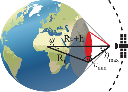
 $^\circ$ for the satellite antennas. Figure 1 illustrates the satellite-Earth geometry. The satellite’s field of view (FoV) and the resulting user coverage are marked in gray and red, respectively.
Satellite–Earth geometry with the satellite’s FoV in gray and the user coverage in red.

In the context of a Ka-band satellite downlink use case, the antenna design in this paper is fundamentally guided by these conditions.
Antenna design
Waveguide-based PAAs pose a challenge because of the conflicting relation between the waveguide cutoff frequency and the optimal grating lobe-free element spacing. Even if grating lobes outside the satellite field of view do not interfere with the communication link, antenna performance is still compromised. For example, the antenna may suffer from degradation in antenna gain, matching, and polarization performance.
To address this conflict, it is necessary to reduce the waveguide cutoff frequency without increasing the waveguide dimensions, increase the element spacing without inducing grating lobes, or employ a combination of both approaches. The waveguide cutoff frequency can be reduced by using dielectric-filled or ridged waveguides. However, dielectric-filled waveguides increase the losses and encounter manufacturing challenges associated with the dielectric filling. Otherwise, recent advances in metal-based additive manufacturing have mitigated previous manufacturing challenges faced by ridged waveguides and enabled a cost-effective realization at cmW and mmW frequencies [Reference Dimitriadis, Favre, Billod, Ansermet and de Rijk20–Reference García-Marín, Masa-Campos, Sanchez-Olivares and Ruiz-Cruz22]. Consequently, ridged waveguide-based PAAs are the preferred solution over dielectric-filled waveguide PAAs for low-loss applications. In addition, employing a triangular lattice and accounting for the maximum required scan range with a 10% margin relaxes the limitation on the element spacing to 0.633 $\lambda_\text{min}$ (9.4 mm). In the recent literature, circular and hexagonal waveguide PAA elements with three and six ridges have been proposed [Reference Pla, Capdevila, Calleau, Toso, Menargues, Gillard and García-Vigueras11–Reference Harms, Fraysse, Monni, Garufo and Johannsen16]. Circular and hexagonal waveguides support the propagation of two orthogonal fundamental modes that are needed to achieve circular polarization.
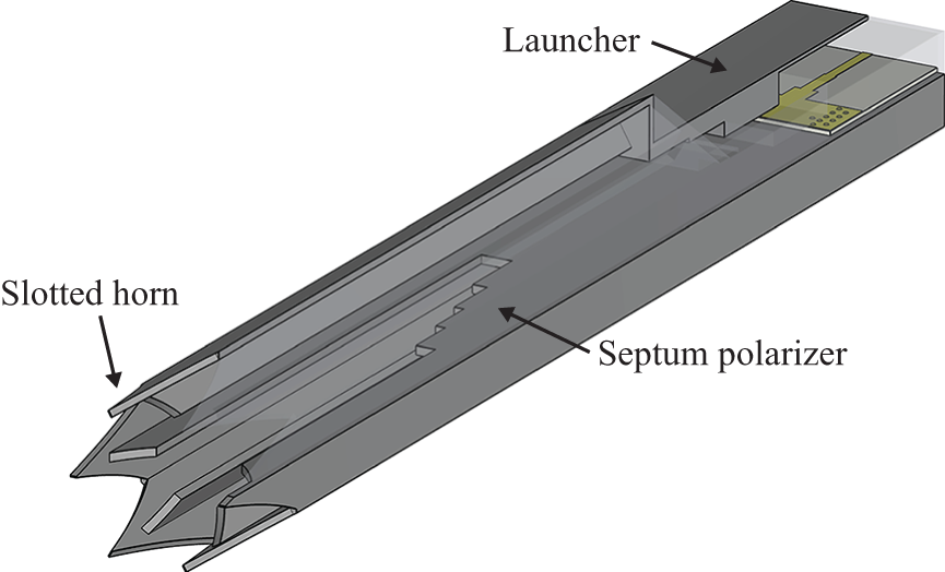
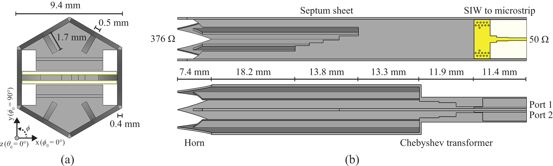
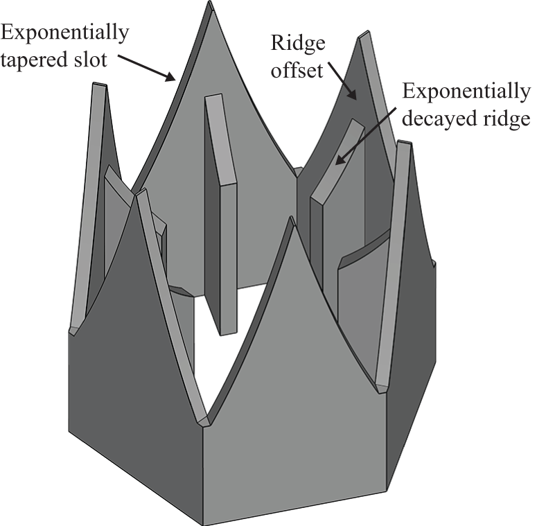
In this work, a hexagonal waveguide with six ridges is chosen because it provides symmetry in all lattice directions and maximizes the element aperture in a triangular lattice. The proposed slotted horn PAA element consists of a wide scan angle matched slotted horn, a septum polarizer, and a launcher. A partially transparent 3D view of the slotted horn PAA element is depicted in fig. 2, and a front view and cross-sections are shown in fig. 3, respectively. The ridges are positioned at the center of each side of the hexagonal waveguide and are dimensioned to reduce the fundamental mode cutoff frequencies to meet the bandwidth requirements and the manufacturing constraints. As a result, the ridge height and width are chosen as 1.7 mm and 0.5 mm, respectively. The total length between the launcher and the aperture is 76 mm.
Partially transparent 3D view of the slotted horn PAA.

Front view and cross sections of the slotted horn PAA element.

Wide scan angle matched slotted horn
A wide scan angle matched slotted horn is added to the H6RWG aperture to stabilize the antenna input impedance versus scan angles. The horn consists of two elements: exponentially tapered wall openings, or slots, on each side of the H6RWG and exponentially decayed ridges. In fig. 4, a close-up view of the slotted horn aperture is depicted. The slots interrupt the surface current flow to neighboring elements at the edges of the hexagon, resulting in reduced mutual coupling compared to an OEWG PAA element. In addition, the slots also lower the waveguide cutoff frequencies, resulting in a smaller waveguide impedance that more closely matches the free space impedance. In the broadside direction, the field is primarily confined between the ridges. Therefore, the slots have a negligible impact. However, for an oblique incidence angle, the slots result in a significantly better impedance matching. The exponentially decayed ridges allow for a uniform impedance matching of the two fundamental waveguide modes at the horn-polarizer interface. The length of the slots ( $\approx$ 0.5 $\lambda_\text{min}=$ 7.4 mm) [Reference Liang, Zhang, Zeng, Guan, Liu and Zi23] and the offset of the exponentially decayed ridges ( $\approx$ 0.23 $\lambda_\text{min}=$ 3.4 mm) are the two key parameters and the result of optimization. The exponential tapering of the slots and the ridges improves the broadband performance.
Close-up view of the wide scan angle matched slotted horn aperture.

Septum polarizer
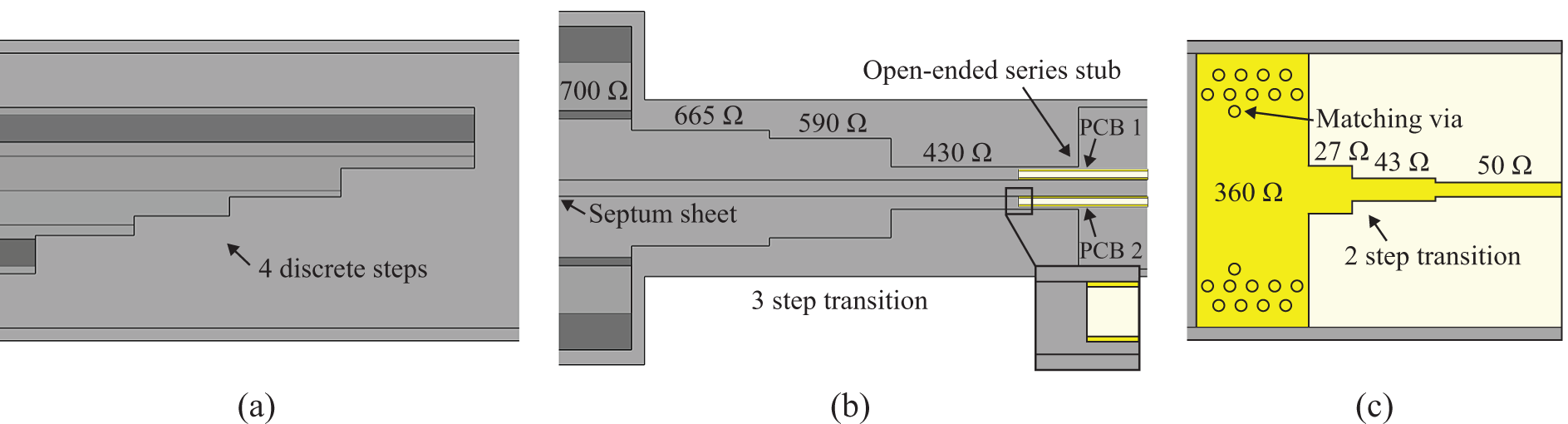
Septum polarizers convert linear polarization to circular polarization and vice versa. A septum sheet is placed between two opposite ridges of the H6RWG, dividing it into two half-H6RWGs as shown in fig. 3. Each half-H6RWG excites either left-hand circular polarization (LHCP) or right-hand circular polarization (RHCP). In [Reference Dubrovka, Piltyay, Dubrovka, Lytvyn and Lytvyn24], septum polarizers in non-ridged square waveguides were analyzed with respect to the relative bandwidth and the number of discrete steps of the septum sheet. For a relative bandwidth of 10 - 20%, a discrete four-step septum sheet is optimal. Simulations confirmed that for the Ka-band downlink application (relative bandwidth of 15.5%), a discrete four-step ridged hexagonal waveguide septum polarizer is also optimal. Figure 5(a) shows a close-up view along the plane of the septum sheet. However, because of the presence of the ridges, limitations were observed in the maximum achievable reflection coefficient, coupling to the cross-polarized input port, and axial ratio (AR) compared to the reported performance of non-ridged square waveguide polarizers [Reference Dubrovka, Piltyay, Dubrovka, Lytvyn and Lytvyn24]. The final dimensions of the four steps are the result of optimization in the broadside direction in the infinite array environment. For the Ka-band satellite downlink use case, only one polarization per antenna is utilized. As a result, only one of the two ports is actively used, and the second port is terminated with a 50  $\Omega$ load.
Close-up views of (a) the septum sheet, (b) the Chebyshev transformer, and (c) the SIW to microstrip transition.

Launcher
Each input port of the septum polarizer is fed through a separate launcher. The launcher realizes a microstrip to waveguide transition and consists of three parts, similar to [Reference Aljarosha, Zaman and Maaskant25]. Figure 5(b) and (c) shows close-up views of the microstrip to waveguide transition. First, a two-step microstrip to substrate-integrated waveguide (SIW) transition is carried out, which matches from 50  $\Omega$ to 360 $\Omega$. A two-layer stack with a copper thickness of 35 $\unicode{x03BC}$m and a substrate height of 254 $\unicode{x03BC}$m is used. Isola Astra MT77 is chosen as the substrate, offering low losses ( $\varepsilon_\text{r}$ = 3, tan( $\delta$) = 0.0017) and space certification. Second, the SIW is contactlessly transformed into a thick, single-ridged rectangular waveguide via an open-ended series stub, resulting in a half-H6RWG impedance of 430 $\Omega$. Inductive matching vias partially compensate for the stub capacitance. The microstrip and SIW transitions are kept short to minimize losses. Third, a three-step Chebyshev transformer converts a single-ridge rectangular waveguide to a double-ridge half-hexagonal waveguide with an impedance of 700 $\Omega$. The printed circuit boards (PCBs) are mounted on a lid that closes the waveguides and connects the PAA inputs with the radio frequency and digital front end.
Antenna simulation results
The PAA elements presented in this paper were simulated using CST and validated in HFSS within an infinite array environment [26, 27]. An infinite array analysis is appropriate, given the intended use of a very large PAA with hundreds of elements to achieve the needed EIRP. To evaluate the performance improvement due to the wide scan angle matched slotted horn, an OEWG PAA element is used for comparison. The OEWG PAA element uses the identical launcher and septum polarizer, with the aperture cut off at the start of the slots. Using an identical feeding for the reference element is fair because the slotted horn has a negligible impact in the broadside direction. Additionally, it enables an independent evaluation of the impact of the slotted horn.
Active S-parameters
The PAA elements can be considered as four-port networks with two input ports, the excited co-polarized input port and the terminated cross-polarized input port, and two output ports, one for each orthogonal linearly polarized radiated electric field component, which together form the circularly polarized radiated field. With the active S-parameters accounting for the mutual coupling due to the array environment, fig. 6 shows the ARCs and the coupling coefficients to the terminated cross-polarized input port of the slotted horn PAA element and the OEWG PAA element at broadside ( $\phi_\text{0}$ = 0 $^\circ$, $\theta_\text{0}$ = 0 $^\circ$) and for a representative selection of scan angles ( $\phi_\text{0}$ = 0, 60, 90 $^\circ$ and $\theta_\text{0}$ = 30, 50 $^\circ$).
Simulated active S-parameters in an infinite array environment at broadside ( $\phi_\text{0}$ = 0 $^\circ$, $\theta_\text{0}$ = 0 $^\circ$) and for a representative selection of scan angles ( $\phi_\text{0}$ = 0, 60, 90 $^\circ$ and $\theta_\text{0}$ = 30, 50 $^\circ$): ARCs for (a) the slotted horn and (b) the OEWG PAA elements, and coupling coefficients for (c) the slotted horn and (d) the OEWG PAA elements.

At broadside, the ARC of the slotted horn PAA element is low and has two resonances at 17.8 GHz and 19.8 GHz, respectively. When scanned, the ARC degrades only slightly and remains below -18 dB for all scan angles. While the OEWG PAA element is also well-matched at broadside, the ARC significantly increases when scanning off broadside and peaks at about -7 dB at 20.2 GHz for  $\phi_\text{0}$ = 90 $^\circ$ and $\theta_\text{0}$ = 50 $^\circ$.
The coupling coefficient of the slotted horn PAA element degrades by 2 dB compared to the OEWG PAA element at broadside, peaking at -11 dB and limiting the performance. Otherwise, the coupling coefficients are significantly improved at high scan angles and frequencies, remaining below -14 dB. In contrast, the coupling coefficients of the OEWG PAA element increase up to -7 dB for  $\phi_\text{0}$ = 90 $^\circ$ and $\theta_\text{0}$ = 50 $^\circ$.
Antenna efficiency
The total antenna efficiency is defined as
 \begin{equation}
\unicode{x03B7}_{\text{antenna,\,total}} = \unicode{x03B7}_{\text{match}} \cdot \unicode{x03B7}_{\text{coup}} \cdot \unicode{x03B7}_{\text{rad}} \text{\,, }
\end{equation}
\begin{equation}
\unicode{x03B7}_{\text{antenna,\,total}} = \unicode{x03B7}_{\text{match}} \cdot \unicode{x03B7}_{\text{coup}} \cdot \unicode{x03B7}_{\text{rad}} \text{\,, }
\end{equation} with  $\unicode{x03B7}_{\text{match}}$ as the matching efficiency defined as
 \begin{equation}
\unicode{x03B7}_{\text{match}} = 1-(\text{ARC})^2
\end{equation}
\begin{equation}
\unicode{x03B7}_{\text{match}} = 1-(\text{ARC})^2
\end{equation} describing miss-matching losses,  $\unicode{x03B7}_{\text{coup}}$ as the coupling efficiency defined as
 \begin{equation}
\unicode{x03B7}_{\text{coup}} = 1-(\text{Coupling coefficient})^2
\end{equation}
\begin{equation}
\unicode{x03B7}_{\text{coup}} = 1-(\text{Coupling coefficient})^2
\end{equation} representing the losses to the terminated cross-polarized port, and  $\unicode{x03B7}_{\text{rad}}$ as the radiation efficiency accounting for conductivity and dielectric losses.
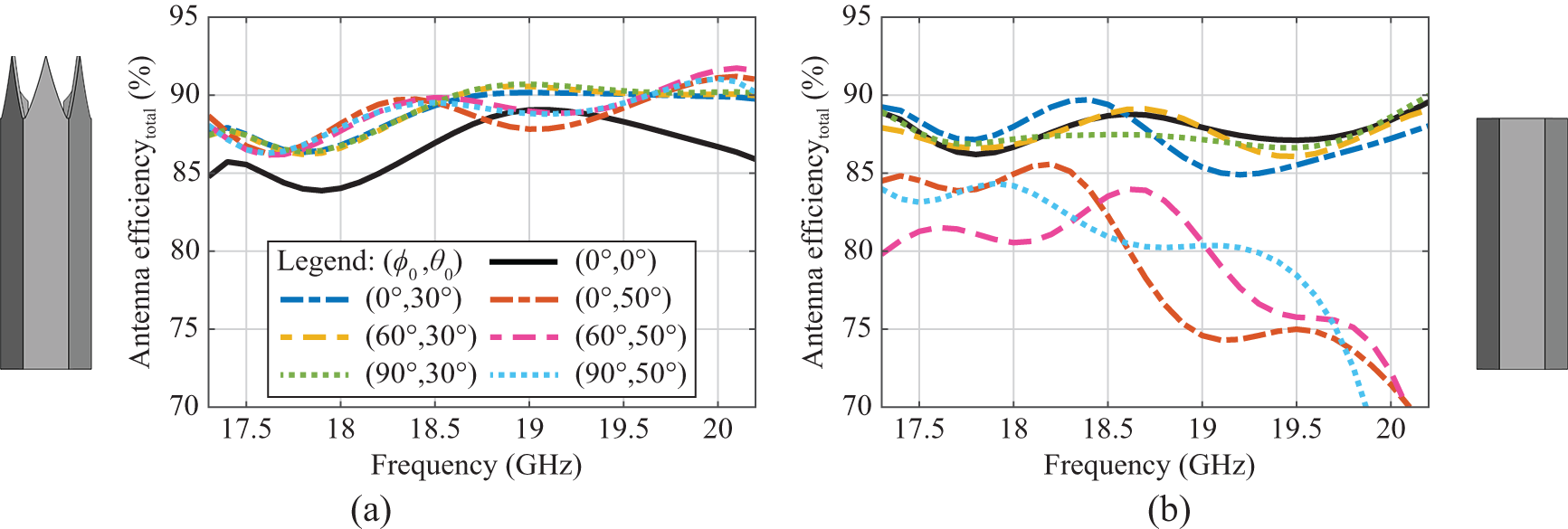
In fig. 7, the total antenna efficiency of the slotted horn PAA element and the OEWG PAA element is shown. The total antenna efficiency of the slotted horn PAA element exceeds 84% for all scan angles, with its minimum efficiency in the broadside direction and showing mostly improvements for higher scan angles in all  $\phi$-planes. The limitation is directly related to the increased coupling coefficient at broadside, see fig. 6(c). Although the OEWG PAA element has slightly higher broadside efficiency, with increasing scan angles, the efficiency drops considerably below 75%.
Simulated total antenna efficiency (matching, coupling, and radiating efficiency) in an infinite array environment at broadside ( $\phi_\text{0}$ = 0 $^\circ$, $\theta_\text{0}$ = 0 $^\circ$) and for a representative selection of scan angles ( $\phi_\text{0}$ = 0, 60, 90 $^\circ$ and $\theta_\text{0}$ = 30, 50 $^\circ$) for (a) the slotted horn and (b) the OEWG PAA elements.

Specifically, matching losses are less than 1.5% for the slotted horn PAA element, while matching losses for the OEWG PAA element reach up to 20% for  $\theta_\text{0}$ = 50 $^\circ$ at 20.2 GHz. The coupling losses are frequency and scan angle dependent as shown in fig. 6(c) and (d), resulting in a degradation of up to 7% for the slotted horn PAA and of up to 13% for the OEWG PAA element. Conductivity losses are mainly caused by the relatively low surface conductivity of 8 MS/m of the metal-printing process, resulting in a degradation of about 5%. The conductivity losses and dielectric losses of the printed circuit board remain below 1.5% and 2.5%, respectively. Approximately 2% of the losses can be attributed to the septum polarizer (excluding coupling losses) and around 6% to the launcher.
Axial ratio
The AR is calculated as
 \begin{equation}
\text{AR} = \sqrt{\frac{\lvert \text{E}_{\theta} \rvert^2 + \lvert \text{E}_{\phi} \rvert^2 + \lvert \text{E}_{\theta}^2 + \text{E}_{\phi}^2 \rvert}
{\lvert \text{E}_{\theta}\rvert^2 + \lvert \text{E}_{\phi} \rvert^2 - \lvert \text{E}_{\theta}^2 + \text{E}_{\phi}^2 \rvert}} \text{, }
\end{equation}
\begin{equation}
\text{AR} = \sqrt{\frac{\lvert \text{E}_{\theta} \rvert^2 + \lvert \text{E}_{\phi} \rvert^2 + \lvert \text{E}_{\theta}^2 + \text{E}_{\phi}^2 \rvert}
{\lvert \text{E}_{\theta}\rvert^2 + \lvert \text{E}_{\phi} \rvert^2 - \lvert \text{E}_{\theta}^2 + \text{E}_{\phi}^2 \rvert}} \text{, }
\end{equation} where  $\text{E}_{\theta}$ and $\text{E}_{\phi}$ are the complex total electric field components in the far-field in a spherical coordinate system.
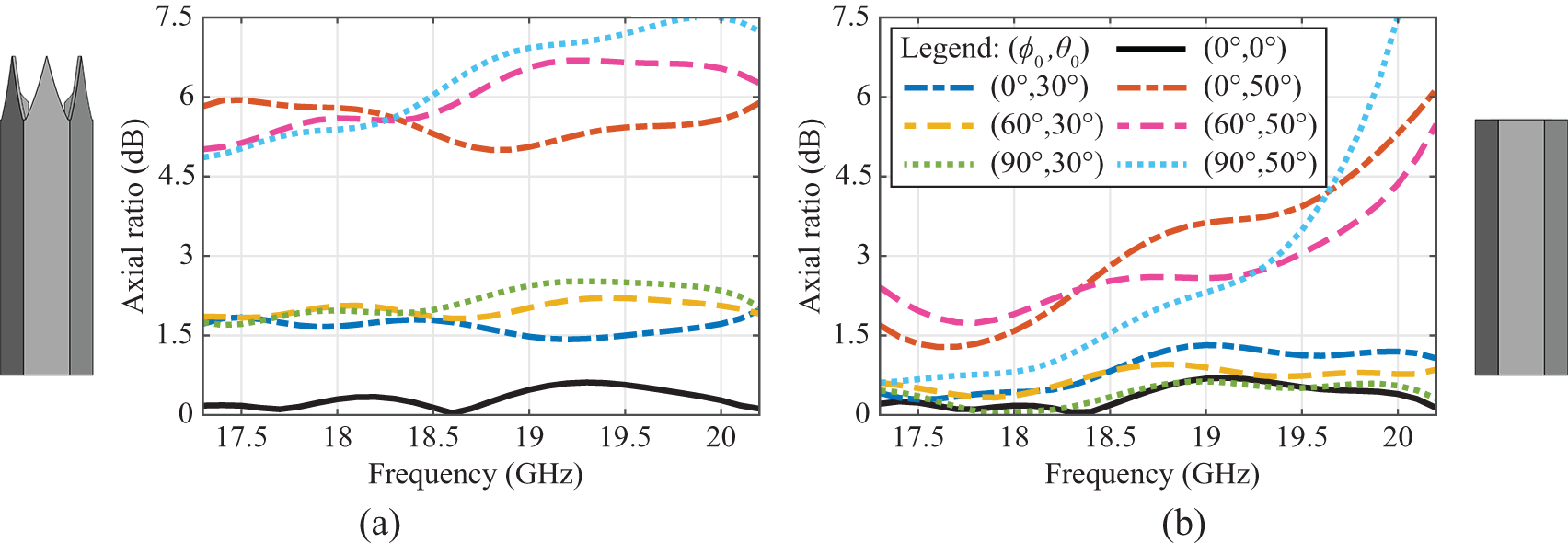
In recent literature, AR degradation of OEWG PAAs has been reported at high scan angles and frequencies [Reference Vazquez-Sogorb, Montoya-Roca, Addamo, Peverini and Virone12, Reference Harms, De Kok, Monni, Garufo, Fraysse, Girard and Johannsen13, Reference Harms, Fraysse, Monni, Garufo and Johannsen16]. The OEWG PAA element used as a reference also suffers from a strong increase in the AR at high scan angles and frequencies, as can be observed in fig. 8(b). This phenomenon is a consequence of single-mode scan blindness due to a fundamental Floquet mode transmission zero just before the onset of the first grating lobe. As a result, only a linear polarized wave is radiated [Reference Harms, Fraysse, Monni, Garufo and Johannsen16].
Simulated AR in an infinite array environment at broadside ( $\phi_\text{0}$ = 0 $^\circ$, $\theta_\text{0}$ = 0 $^\circ$) and for a representative selection of scan angles ( $\phi_\text{0}$ = 0, 60, 90 $^\circ$ and $\theta_\text{0}$ = 30, 50 $^\circ$) for (a) the slotted horn and (b) the OEWG PAA elements.

In contrast to the OEWG PAA element, the AR of the slotted horn PAA element behaves differently. As can be observed in fig. 8(a), the AR increases continuously with the scan angle  $\theta$. While the AR remains below 0.7 dB at broadside, it peaks at 7.5 dB at a maximum scan angle of $\theta_\text{0}$ = 50 $^\circ$ for $\phi_\text{0}$ = 90 $^\circ$. The 3 dB threshold is exceeded for scan angles greater than 33 $^\circ$. To explain the underlying effect, a more detailed investigation of the AR degradation is required.
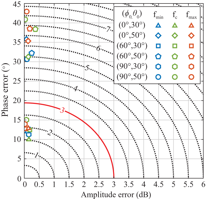
Figure 9 shows the absolute amplitude errors versus phase errors of the orthogonal electric far-field components. Small amplitude errors of less than 0.5 dB are observed, indicating equally well-matched fundamental waveguide modes at the horn-polarizer interface. However, large phase errors between the two orthogonal field components are observed, leading to the strong degradation of the AR. For  $\theta_\text{0}$ = 30 $^\circ$, the phase errors remain below 15 $^\circ$, resulting in AR values below 3 dB, while for $\theta_\text{0}$ = 50 $^\circ$ phase errors of up to 42.5 $^\circ$ are observed. The deviation with frequency and $\phi$-angle are small for a fixed scan angle $\theta$. Nevertheless, depending on the $\phi$-angle, either one or both of the two fundamental waveguide modes are affected by phase shifts, resulting in the observed absolute phase error. Because the phase error affects the waveguide modes differently for each scan direction, passive compensation, for instance, by the septum polarizer, is not possible.
Absolute amplitude versus phase errors of the orthogonal electric far-field components for 17.3 GHz (f $_\text{min}$), 18.75 GHz (f $_\text{c}$), and 20.2 GHz (f $_\text{max}$) for $\theta_\text{0}$ = 30 $^\circ$ and 50 $^\circ$ and $\phi_\text{0}$ = 0 $^\circ$, 60 $^\circ$ and 90 $^\circ$.

Embedded element pattern
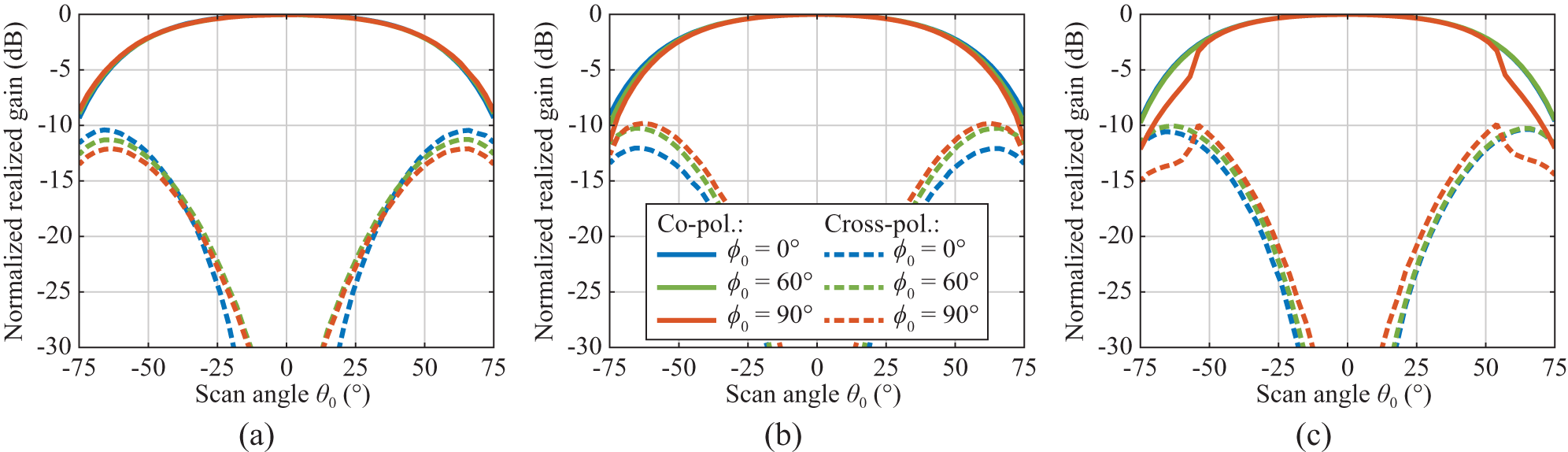
The embedded element patterns were extracted for each scan angle  $\theta_\text{0}$ from the realized co-polarized and cross-polarized gains in each $\phi_\text{0}$-plane within the infinite array environment. Figure 10 shows the normalized co-polarized and cross-polarized embedded element patterns of the slotted horn PAA element versus scan angle $\theta_\text{0}$ at the minimum frequency (17.3 GHz), the center frequency (18.75 GHz), and the maximum frequency (20.2 GHz) for $\phi_\text{0}$ = 0 $^\circ$, 60 $^\circ$, and 90 $^\circ$. The co-polarized realized gain peaks between 4.3 and 5.7 dBi along the frequency range at broadside and decreases between 2 and 2.3 dB at $\theta_\text{0}$ = 50 $^\circ$. Due to the increasing phase errors between the orthogonal field components with scan angle $\theta$, the cross-polarized gain also increases with the scan angle $\theta$, peaking at about -11 dB below the broadside at 20.2 GHz for $\phi_\text{0}$ = 0 $^\circ$ and $\theta_\text{0}$ = 50 $^\circ$. Likewise, the co-polarized embedded element pattern of the OEWG PAA element behaves almost identically. Otherwise, the cross-polarized embedded element pattern of the OEWG PAA element increases less strongly at 17.3 GHz and 18.75 GHz. However, at 20.2 GHz, the degradation is similar to that of the slotted horn PAA element.
Simulated co- and cross-polarized embedded element pattern of the slotted horn PAA element in an infinite array environment versus scan angle  $\theta_\text{0}$ for $\phi_\text{0}$ = 0 $^\circ$, 60 $^\circ$, and 90 $^\circ$ at (a) 17.3 GHz, (b) 18.75 GHz, and (c) 20.2 GHz.

Power amplifier and antenna co-simulation
To evaluate the effect of the slotted horn aperture on the PA performance and, hence, on the performance of the active phased array antenna (APAA) over the entire scan and frequency range, both PAA elements are co-simulated with a basic PA. The PA is synthesized using the MATLAB model described in [Reference de Kok, Monni, van Heijningen, Garufo, de Hek, Smolders and Johannsen28], which combines load-pull contours with the scan-dependent ARCs from full-wave antenna simulations. The model can generate on- and off-chip power combining and matching networks and includes a bondwire model. Since the model is intended to enable rapid comparisons between technologies and matching strategies of integrated PAs and PAAs and not to generate fully optimized broadband designs, the synthesized PA is optimized and co-simulated in ADS [29].
Based on a 0.15  $\mu$m Gallium Nitride (GaN) process by United Monolithic Semiconductors (UMS), the PA consists of a single high-electron-mobility transistor (HEMT) with eight $50\,\mu\mathrm{m}$-wide gate fingers, and is biased in class-AB operation (V $_\text{gate}$ = -3 V, V $_\text{drain}$ = 20 V). The optimal input impedance of the transistor is chosen to maximize the power-added efficiency (PAE) within the bandwidth, while maintaining a power delivered to the antenna ( $\text{P}_\text{ant}$) of more than 30 dBm and a carrier over third-order intermodulation products (C/I3) of more than 15 dBc at the optimum load impedance. The PAE is maximized for an input power of 21.5 dBm, resulting in a large signal gain of about 10 dB.
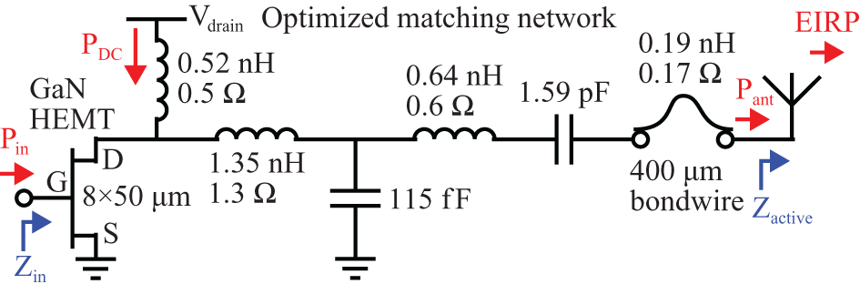
A circuit schematic of the APAA is given in fig. 11. The transistor load is matched to the active input impedance in the broadside direction of the slotted horn PAA element and the OEWG PAA element, which are almost identical, allowing for a fair comparison. Thereby, the reactive component is compensated for by the bias inductor. A two-stage L-C network realizes the impedance matching by considering the bondwire inductance. The component values result from an optimization in ADS. For the given bias point and load, the PA has a DC power consumption of about 2 W at the center frequency with a  $\pm$ 0.1 W variation with frequency.
Circuit schematic of the APAA with a PA based on a GaN HEMT, a two-stage L-C network, and a bondwire connection to the antenna.

Power amplifier performance
In fig. 12, the ARCs throughout the scan range are shown alongside the PA load pull contours for PAE, power delivered to the antenna, and C/I3 at the PA-antenna interface for both the slotted horn and the OEWG PAA elements at 17.3 GHz, 18.75 GHz, and 20.2 GHz. The slotted horn PAA element shows clearly fewer variations in ARC during scanning than the OEWG PAA element.
PAE, power delivered to the antenna ( $\text{P}_{\text{ant}}$), and C/I3 contours at the (a) 17.3 GHz, (b) 18.75 GHz, and (c) 20.2 GHz, based on the matching circuit shown in fig. 11. The ARCs throughout the scan range ( $\Delta\phi$ = 7.5 $^\circ$, $\Delta\theta$ = 2.5 $^\circ$) are shown for the slotted horn PAA and the OEWG PAA.

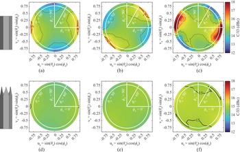
Figures 13–15 show the PAE, the power delivered to the antenna, and the C/I3 in the UV-plane for the slotted horn APAA element and the OEWG APAA element at 17.3 GHz, 18.75 GHz, and 20.2 GHz for a two-tone excitation with a 10 kHz spacing. The PAE is defined as
 \begin{equation}
\text{PAE} = \frac{\text{P}_\text{ant}-\text{P}_\text{in}}{\text{P}_\text{DC}}\text{\,, }
\end{equation}
\begin{equation}
\text{PAE} = \frac{\text{P}_\text{ant}-\text{P}_\text{in}}{\text{P}_\text{DC}}\text{\,, }
\end{equation}PAE versus scan range of the OEWG PAA at (a) 17.3 GHz, (b) 18.75 GHz, and (c) 20.2 GHz and of the slotted horn PAA at (d) 17.3 GHz, (e) 18.75 GHz, and (f) 20.2 GHz.

Delivered power to the antenna versus scan range of the OEWG PAA at (a) 17.3 GHz, (b) 18.75 GHz, and (c) 20.2 GHz and of the slotted horn PAA at (d) 17.3 GHz, (e) 18.75 GHz, and (f) 20.2 GHz.

C/I3 versus scan range of the OEWG PAA at (a) 17.3 GHz, (b) 18.75 GHz, and (c) 20.2 GHz and of the slotted horn PAA at (d) 17.3 GHz, (e) 18.75 GHz, and (f) 20.2 GHz.

with  $P_\text{in}$ the power accepted by the PA and $P_\text{DC}$ as the DC power consumption of the PA. Further, the delivered power to the antenna is defined as
 \begin{equation}
\text{P}_{\text{ant}} = \text{P}_{\text{f}_{\text{1}}} + \text{P}_{\text{f}_{\text{2}}} \text{\,, }
\end{equation}
\begin{equation}
\text{P}_{\text{ant}} = \text{P}_{\text{f}_{\text{1}}} + \text{P}_{\text{f}_{\text{2}}} \text{\,, }
\end{equation} with  $\text{P}_{\text{f}_{\text{1}}}$ and $\text{P}_{\text{f}_{\text{2}}}$ as the fundamental tone powers delivered to the antenna. The C/I3 is defined as
 \begin{equation}
\text{C/I3} = \frac{\text{C/I3}_{\text{lower}}+\text{C/I3}_{\text{upper}}}{2} \text{\,, }
\end{equation}
\begin{equation}
\text{C/I3} = \frac{\text{C/I3}_{\text{lower}}+\text{C/I3}_{\text{upper}}}{2} \text{\,, }
\end{equation}while
 \begin{equation}
\text{C/I3}_{\text{lower}} = \frac{\text{P}_{\text{ant}}}{\text{P}_{2\text{\,f}_{\text{1}}-\text{f}_{\text{2}}}}
\end{equation}
\begin{equation}
\text{C/I3}_{\text{lower}} = \frac{\text{P}_{\text{ant}}}{\text{P}_{2\text{\,f}_{\text{1}}-\text{f}_{\text{2}}}}
\end{equation} \begin{equation}
\text{C/I3}_{\text{upper}} = \frac{\text{P}_{\text{ant}}}{\text{P}_{2\text{\,f}_{\text{2}}-\text{f}_{\text{1}}}} \text{\,, }
\end{equation}
\begin{equation}
\text{C/I3}_{\text{upper}} = \frac{\text{P}_{\text{ant}}}{\text{P}_{2\text{\,f}_{\text{2}}-\text{f}_{\text{1}}}} \text{\,, }
\end{equation} with  $\text{P}_{2\text{\,f}_{\text{1}}-\text{f}_{\text{2}}}$ and $\text{P}_{2\text{\,f}_{\text{2}}-\text{f}_{\text{1}}}$ as the power of the third-order inter-modulation products delivered to the antenna.
At broadside, both APAA elements achieve a PAE peak of about 49% at 17.3 GHz, with a degradation of up to 2% with increasing frequency. The slotted horn APAA element has almost no degradation in the entire scan range, compared to up to 10% for the OEWG APAA element at 20.2 GHz.
The power delivered to the antenna and the C/I3 are about 31 dBm and 15 dBc, respectively, and behave similarly to the PAE. While the slotted horn APAA element has almost no degradation in the scan range, the OEWG element degrades up to 3 dB for the power delivered to the antenna and varies of up to  $\pm$ 3 dB for the C/I3.
For the slotted horn APAA element, the DC power has no variation over the scan range. On the contrary, the OEWG APAA element has a variation of up to  $\pm$ 0.6 W within the scan range. Similar observations can be made for the dissipated power. For both APAA elements, the dissipated power is about 0.9 W at broadside with a variation of $\pm$ 0.05 W with frequency. While the slotted horn APAA element has no variation with the scan range, the dissipated power of the OEWG APAA element increases up to 1.5 W.
System performance
The co-polarized system efficiency and the co- and cross-polarized EIRP are evaluated to assess the system performance of the APAA elements. Thereby, the co-polarized system efficiency is defined as
 \begin{equation}
\unicode{x03B7}_{\text{system,\,co-pol}} = \frac{\text{P}_\text{ant}\cdot \unicode{x03B7}_{\text{coup}} \cdot \unicode{x03B7}_{\text{rad}} \cdot \unicode{x03B7}_{\text{co-pol}}-\text{P}_\text{in}}{\text{P}_\text{DC}} \text{\,, }
\end{equation}
\begin{equation}
\unicode{x03B7}_{\text{system,\,co-pol}} = \frac{\text{P}_\text{ant}\cdot \unicode{x03B7}_{\text{coup}} \cdot \unicode{x03B7}_{\text{rad}} \cdot \unicode{x03B7}_{\text{co-pol}}-\text{P}_\text{in}}{\text{P}_\text{DC}} \text{\,, }
\end{equation} with  $\unicode{x03B7}_{\text{co-pol}}$ as the polarization efficiency of the radiated co-polarized electric field. Similarly, the co- and cross-polarized EIRP can be defined as
 \begin{equation}
\text{EIRP}_{\text{co-pol}} = \text{P}_\text{ant} \cdot \text{D} \cdot \unicode{x03B7}_{\text{coup}} \cdot \unicode{x03B7}_{\text{rad}} \cdot \unicode{x03B7}_{\text{co-pol}}
\end{equation}
\begin{equation}
\text{EIRP}_{\text{co-pol}} = \text{P}_\text{ant} \cdot \text{D} \cdot \unicode{x03B7}_{\text{coup}} \cdot \unicode{x03B7}_{\text{rad}} \cdot \unicode{x03B7}_{\text{co-pol}}
\end{equation} \begin{equation}
\text{EIRP}_{\text{cross-pol}} = \text{P}_\text{ant} \cdot \text{D} \cdot \unicode{x03B7}_{\text{coup}} \cdot \unicode{x03B7}_{\text{rad}} \cdot \unicode{x03B7}_{\text{cross-pol}} \text{\,, }
\end{equation}
\begin{equation}
\text{EIRP}_{\text{cross-pol}} = \text{P}_\text{ant} \cdot \text{D} \cdot \unicode{x03B7}_{\text{coup}} \cdot \unicode{x03B7}_{\text{rad}} \cdot \unicode{x03B7}_{\text{cross-pol}} \text{\,, }
\end{equation} where D is the directivity of the antenna and  $\unicode{x03B7}_{\text{cross-pol}}$ as the polarization efficiency of the radiated cross-polarized electric field.
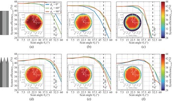
Figure 16 shows the co-polarized system efficiency versus scan angle  $\theta_\text{0}$ for $\phi_\text{0}$ = 0 $^\circ$, 60 $^\circ$, and 90 $^\circ$ at 17.3 GHz, 18.75 GHz, and 20.2 GHz for the slotted horn APAA element and the OEWG APAA element. While the OEWG APAA element exhibits a strong decrease of more than 14% in system efficiency for high scan angles and frequencies, the slotted horn APAA element degrades only up to 8%. The degradation of the slotted horn APAA element is mainly due to the increase in AR, which causes the polarization efficiency to drop to 80% at the maximum scan angles of $\theta_\text{0}$ = 50 $^\circ$. Otherwise, for the OEWG APAA element, the co-polarized system efficiency decreases with increasing scan angle in PAE and radiation efficiency. Only at high frequencies and scan angles does the polarization efficiency also degrade significantly.
Co-polarized system efficiency versus scan angle  $\theta_\text{0}$ for $\phi_\text{0}$ = 0 $^\circ$, 60 $^\circ$, and 90 $^\circ$ of the OEWG APAA element at (a) 17.3 GHz, (b) 18.75 GHz, and (c) 20.2 GHz and of the slotted horn APAA element at (d) 17.3 GHz, (e) 18.75 GHz, and (f) 20.2 GHz. Small UV-plots within the figures provide a rough indication of the entire scan range.

Similarly, fig. 17 and 18 show the co- and cross-polarized EIRP of the APAA elements, respectively, as a function of the scan angle  $\theta_\text{0}$ for $\phi_\text{0}$ = 0 $^\circ$, 60 $^\circ$, and 90 $^\circ$ at 17.3 GHz, 18.75 GHz, and 20.2 GHz. The co-polarized EIRP of both APAA elements is between 35 and 36 dBm at broadside across the frequency band and decreases with scan angle $\theta_\text{0}$. The scan losses of the OEWG APAA element are approximately 3 dB at the maximum scan angle at most frequencies, but increase up to 7 dB for $\phi_\text{0}$ = 90 $^\circ$ and $\theta_\text{0}$ = 50 $^\circ$ at 20.2 GHz. In contrast, the slotted horn APAA element shows scan losses of about 2.5 dB at the maximum scan angle $\theta_\text{0}$ in the entire scan and frequency range. The cross-polarized EIRP increases with scan angle $\theta_\text{0}$ for both APAAs. For the OEWG APAA element, the maximum cross-polarized EIRP increases with frequency from about 15 dBm at 17.3 GHz up to 26 dBm at 20.2 GHz. In contrast, the cross-polarized EIRP of the slotted horn APAA element remains constant across the frequency band and the scan angle $\phi_\text{0}$, but increases with the scan angle $\theta_\text{0}$, peaking at around 25 dBm at the maximum scan angle of $\theta_\text{0}$ = 50 $^\circ$.
Co-polarized EIRP versus scan angle  $\theta_\text{0}$ for $\phi_\text{0}$ = 0 $^\circ$, 60 $^\circ$, and 90 $^\circ$ of the OEWG APAA element at (a) 17.3 GHz, (b) 18.75 GHz, and (c) 20.2 GHz and of the slotted horn APAA at (d) 17.3 GHz, (e) 18.75 GHz, and (f) 20.2 GHz. Small UV-plots within the figures provide a rough indication of the entire scan range.

Cross-polarized EIRP versus scan angle  $\theta_\text{0}$ for $\phi_\text{0}$ = 0 $^\circ$, 60 $^\circ$, and 90 $^\circ$ of the OEWG APAA element at (a) 17.3 GHz, (b) 18.75 GHz, and (c) 20.2 GHz and of the slotted horn APAA at (d) 17.3 GHz, (e) 18.75 GHz, and (f) 20.2 GHz. Small UV-plots within the figures provide a rough indication of the entire scan range.

Conclusion
This paper introduced an H6RWG PAA element featuring a wide scan angle matched slotted horn aperture. The proposed aperture was designed to limit the variation of the ARC during scanning, achieving a very low ARC of less than -18 dB for scan angles up to  $\pm$ 50 $^\circ$ from 17.3 GHz to 20.2 GHz. Further, a total antenna efficiency of more than 84% was achieved.
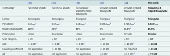
In Table 1, the slotted horn PAA element is compared with other full-metal PAA elements from the literature. Although the full-metal Vivaldi PAA elements in [Reference Ma, Guan, Li, Fan and Chen30] and [Reference Kähkönen, Ala-Laurinaho and Viikari31] exhibit wideband performance, they typically suffer from poor cross-polarization in the diagonal plane and support only linear polarization. While the rectangular dielectric-filled waveguide PAA element presented in [Reference Liang, Zhang, Zeng, Guan, Liu and Zi23] shows good performance over a wide bandwidth and scan range, it also supports only linear polarization. An extension to circular polarization, using a square dielectric-filled waveguide in a rectangular lattice, showed a reduction in bandwidth and degradation in ARC at the maximum scan angle in the diagonal plane. The circular 3-ridged choked horn waveguide PAA elements in [Reference Pla, Capdevila, Calleau, Toso, Menargues, Gillard and García-Vigueras11] and [Reference Polo-López, Berretti, Menargues, Capdevila, Toso and Garcia-Vigueras15] support circular polarization over wide scan ranges, but are limited in terms of ARC and AR bandwidth. In this context, the slotted horn PAA element stands out because of its very low ARC at high scan angles.
Comparison with full-metal PAA elements from the literature

1 Calculated from reported data.  $^2$ No simulation or measurement results versus frequency or scan angle are reported. $^3$ Degradation at low frequencies at the maximum scan angle.
Nevertheless, a broadband degradation of the AR was observed. The degradation is caused by a large phase error between the two orthogonal radiated field components. The absolute phase error increased with the scan angle  $\theta$, while showing only a small deviation with $\phi$-angle and frequency. Since the phase error cannot be attributed to a specific waveguide mode, passive compensation, for instance, by the septum polarizer, is not feasible, necessitating improvement in the future.
Overall, the proposed slotted horn aperture produces a significant improvement in the antenna input impedance stabilization, which minimizes the active load pulling on active devices, as demonstrated with a PA in a co-simulation. As a result, PAE, power delivered to the antenna, and C/I3 were maintained with negligible degradation throughout the whole  $\pm$ 50 $^\circ$ scan range and bandwidth. Although the increased AR resulted in a degradation of the polarization efficiency with increasing scan angle, the co-polarized system efficiency and EIRP were improved at most frequencies and high scan angles compared to an OEWG aperture.
Acknowledgements
Funded by the European Union, under ANTERRA 101072363 HORIZON-MSCA-2021-DN-01. Views and opinions expressed are however those of the author(s) only and do not necessarily reflect those of the European Union. Neither the European Union nor the granting authority can be held responsible for them.
Competing interests
The author(s) declare none.

Sören Harms graduated with distinction in Electrical Engineering and Information Technology from Karlsruhe Institute of Technology, Germany, in 2023. In 2019, he was a student intern at the Alaska Satellite Facility, USA. From 2019 to 2023, he was also a student research assistant at the Fraunhofer Institute for High Frequency Physics and Radar Techniques, Germany. He is currently a research engineer at Thales Alenia Space in Toulouse, France, and enrolled as a Ph.D. student in Electrical Engineering at Eindhoven University of Technology, The Netherlands. He is also a guest researcher in the antenna team at the Radar Technology Group of TNO Defense, Safety and Security in The Hague, The Netherlands. His research focuses on active phased array antennas for low Earth orbit Ka-band satellite downlink, with particular emphasis on the co-design of power amplifiers and phased array antennas.

Martijn de Kok received the B.Sc. and M.Sc. degrees in Electrical Engineering (both cum laude) from Eindhoven University of Technology (TU/e), The Netherlands, in 2018 and 2020, respectively. He is currently pursuing a Ph.D. degree at TU/e. In 2019, he was a visiting student at the Advanced RF & Optical Technologies Group of the Jet Propulsion Laboratory, California Institute of Technology. In September 2021, he became a guest researcher at the Radar Technology Group of TNO Defense, Safety and Security in The Hague. In 2025, he joined TNO as a scientist. His research interests include integrated millimeter-wave antenna systems and phased arrays for next-generation (satellite) communications and radar sensing.

Stefania Monni was born in Cagliari, Italy, in 1974. She obtained her M.Sc. degree in Electronic Engineering from the University of Cagliari, Italy, in 1999 and her Ph.D. degree in Electrical Engineering from the Eindhoven University of Technology, The Netherlands, in 2005. She is currently a senior scientist at the TNO Radar Technology Department. Since 2014, she has led the antenna team, where she is responsible for the definition and technical coordination of the research activities and for the long-term strategy. Since 2018, she has also been a senior scientist at the Chip Integration Technology Center, RF Packaging Program. In 2024, she joined the Eindhoven University of Technology as a part-time professor. Since 2022, she has been president of the European Association on Antennas and Propagation. Her research interests include active array antennas, frequency selective surfaces, and advanced manufacturing technologies.

Alessandro Garufo received the B.Sc. and M.Sc. degrees in Telecommunication Engineering from the University of Siena, Siena, Italy, in 2007 and 2012, respectively, and the Ph.D. degree in Applied Electromagnetism and THz Technology from the Delft University of Technology, Delft, The Netherlands, in 2017. From 2012 to 2018, he was a Ph.D. researcher and then a postdoctoral researcher at the THz Sensing Group, Microelectronics Department, Delft University of Technology, Delft, The Netherlands. From 2013 to 2014, he was a Visiting Scholar with the Metamaterials and Plasmonics Research Laboratory of the University of Texas at Austin, TX, USA. Since 2018, he has worked at TNO Defense, Safety and Security, The Hague, The Netherlands, as a scientist in the Antenna Group of the Radar Technology Department. He is a senior member of IEEE and a member of EurAAP. His research interests are phased array antennas, integrated antennas, quasi-optical systems, lens antennas, reflectarray, transmitarray, frequency selective surfaces, and THz photoconductive antennas.

Jean-Philippe Fraysse received the M.Sc. degree in Microwaves and the Ph.D. degree in Electronics from the University of Limoges in 1995 and 1999, respectively. He joined the research department of Alcatel Space, Toulouse, France, in 1999, where he was an MMIC designer. He is currently with the Research, Technology and Product Department, Thales Alenia Space, where he is an expert in integrated active antenna architectures. His research interests include advanced designs of key building blocks of active antennas, RF/antenna co-design with enabling technologies, and architecture trade-offs for advanced active antenna systems.

Thierry Girard was born in Tours, France, in September 1972. He received his M.Sc. degree from the University of Rennes in 1995 and his Ph.D. degree in Electronics from the University of Nice Sophia-Antipolis, France, in 1999. In 2001, he joined Thales Alenia Space, where he is currently a radio frequency hardware engineer. His main research interests include active antenna arrays and reconfigurable active antennas with analog and digital beamformers. He is also an internal trainer at Thales Alenia Space for active antennas.

Ulf Johannsen received his Dipl.-Ing. degree in Communications Engineering from Hamburg University of Technology, Germany, in 2009, and his Ph.D. degree in Electrical Engineering from Eindhoven University of Technology (TU/e), The Netherlands, in 2013. From 2013 to 2016, he worked as a senior system engineer for autonomous underwater vehicle systems with sonar payloads at ATLAS ELEKTRONIK GmbH in Bremen, Germany. Since 2016, he has been working in the Electromagnetics Group at the TU/e Department of Electrical Engineering, where he currently holds the position of an associate professor. He is the head of the EM Antenna Systems Lab and, since September 2023, the director of the Center for Wireless Technology at TU/e. He is also a member of the advisory board of the Chip Integration Technology Center, The Netherlands, and an independent technology advisor to ASTRON’s Smart Frontend Group.


 Open access