


1. Introduction
In this work, we present steps towards the design of a stellarator fusion power plant, combining several useful properties for plasma confinement, plasma stability and device feasibility into a single concept. We must also stress that, while significant progress has been achieved in stellarator theory and design, there still exist several unanswered questions in theoretical and experimental stellarator physics that must be solved before the viability of a fusion power plant can reasonably be assessed. Further, experimental validation of current and future theories remains elusive; slow, careful, rigorous scientific study is still needed to meld theory and experiment. This work, and others like it, must be understood in this context.
By employing a carefully shaped magnetic field that entwines the torus both toroidally and poloidally, stellarators are able to confine ionised plasmas without the need for a net toroidal current. This comes at a cost: whereas the axisymmetric geometry of a tokamak’s plasma is guaranteed to prevent collisionless fast particles generated by fusion reactions from escaping, the complex geometry of a stellarator generally does not. As such, stellarator plasma geometries must be carefully tailored – usually through numerical optimisation − to be omnigenous, meaning that these particles remain confined.
If a stellarator plasma is designed to be quasi-isodynamic (QI) (Gori, Lotz & Nührenberg Reference Gori, Lotz and Nührenberg1997), it will be omnigenous by definition (Cary & Shasharina Reference Cary and Shasharina1997). In addition, while non-QI stellarators will generally experience a net toroidal bootstrap current in their plasmas, which can give rise to current-driven instabilities and other problematic effects, this current vanishes in well-optimised QI stellarators (Helander & Nührenberg Reference Helander and Nührenberg2009; Helander, Geiger & Maaßberg Reference Helander, Geiger and Maaßberg2011; Goodman et al. Reference Goodman, Camacho Mata, Henneberg, Jorge, Landreman, Plunk, Smith, Mackenbach, Beidler and Helander2023; Sánchez et al. Reference Sánchez, Velasco, Calvo and Mulas2023; Goodman et al. Reference Goodman, Xanthopoulos, Plunk, Smith, Nührenberg, Beidler, Henneberg, Roberg-Clark, Drevlak and Helander2024). Quasi-isodynamic stellarators can thus operate with effectively zero net toroidal current, inoculating them from current-driven instabilities. It was shown by Goodman et al. (Reference Goodman, Xanthopoulos, Plunk, Smith, Nührenberg, Beidler, Henneberg, Roberg-Clark, Drevlak and Helander2024) that stellarators can be designed with reactor-relevant QI quality through numerical optimisation, and that this reduction in bootstrap current is indeed observed. A more complete description of the definition of a QI stellarator is given by Goodman et al. (Reference Goodman, Camacho Mata, Henneberg, Jorge, Landreman, Plunk, Smith, Mackenbach, Beidler and Helander2023, Reference Goodman, Xanthopoulos, Plunk, Smith, Nührenberg, Beidler, Henneberg, Roberg-Clark, Drevlak and Helander2024).
To be a power plant candidate, stellarators and tokamaks alike must additionally be resilient to large-scale magnetohydrodynamic (MHD) instabilities, and have low levels of plasma turbulence. The largest stellarator in the world, Wendelstein 7-X in Greifswald, Germany, was designed with excellent MHD stability, but its performance is limited by turbulent heat losses (Bähner et al. Reference Bähner2021). In Goodman et al. (Reference Goodman, Xanthopoulos, Plunk, Smith, Nührenberg, Beidler, Henneberg, Roberg-Clark, Drevlak and Helander2024), MHD stable, QI designs with reduced ion-temperature-gradient driven turbulence were found, and given the moniker ‘SQuIDs’. Satisfying these properties, SQuIDs meet the minimum requirements for practical stellarator designs.
Missing from the original SQuIDs are two important features: first, these fields must be compatible with some set of electromagnetic coils that can reproduce them. A practical set of coils should be buildable using modern technology, as far from the plasma boundary as possible and, of course, must faithfully produce the desired magnetic field. Efforts to find such a coil set for the original configurations appearing in Goodman et al. (Reference Goodman, Xanthopoulos, Plunk, Smith, Nührenberg, Beidler, Henneberg, Roberg-Clark, Drevlak and Helander2024) have failed.
Second, highly charged impurity ions can poison plasma performance in both stellarators and tokamaks by causing excessive radiation losses, and it would be desirable for a fusion power plant design to remove any mechanisms that might cause increased retention of these impurities. Unfortunately, efforts to improve overall plasma confinement generally result in better impurity confinement as well. The SQuID found in Goodman et al. (Reference Goodman, Xanthopoulos, Plunk, Smith, Nührenberg, Beidler, Henneberg, Roberg-Clark, Drevlak and Helander2024), in particular, has notably poor neoclassical impurity transport properties.
In this work, we present a SQuID that retains all the desirable properties of the configuration presented by Goodman et al. (Reference Goodman, Xanthopoulos, Plunk, Smith, Nührenberg, Beidler, Henneberg, Roberg-Clark, Drevlak and Helander2024), that additionally remedies both of these unresolved problems. This was accomplished by implementing the findings of Kappel, Landreman & Malhotra (Reference Kappel, Landreman and Malhotra2024), who developed a figure-of-merit for a field’s coil compatibility, and by designing the equilibrium to have an electron root such that the radial electric field within the plasma that points outward towards the plasma boundary (Beidler et al. Reference Beidler, Drevlak, Geiger, Helander, Smith and Turkin2024; Helander et al. Reference Helander, Goodman, Beidler, Kuczynski and Smith2024; Lascas Neto et al. Reference Lascas Neto, Jorge, Beidler and Lion2025). This causes impurities, having large masses and positive charges, to meander out of the centre of the plasma through neoclassical transport whilst leaving the bulk plasma sufficiently well confined. At the point where the radial electric field switches directions (pointing inwards, rather than outwards), there is the additional possibility of an internal plasma transport barrier, but this possibility is not investigated in this work. Outward-pointing radial electric fields are generally impossible in fusion-relevant tokamak plasmas and have until recently been thought to be so in stellarators as well (Helander et al. Reference Helander, Goodman, Beidler, Kuczynski and Smith2024).
To complete this concept, we also include a rudimentary divertor design concept using the approach detailed by Davies et al. (Reference Davies, Feng, Boeyaert, Schmitt, Gerard, Garcia, Schmitz, Geiger and Henneberg2024).
2. Methods
2.1. Stage 1
The goal of so-called stage 1 stellarator optimisation is to find a plasma geometry that satisfies various physics goals. The standard stage 1 optimisation inputs are the Fourier coefficients of the plasma’s last closed flux surface, $r_{mn}$
and
$r_{mn}$
and $z_{mn}$
. These map onto the boundary’s shape in cylindrical coordinates
$z_{mn}$
. These map onto the boundary’s shape in cylindrical coordinates $(R,Z,\phi )$
as follows:
$(R,Z,\phi )$
as follows:
 \begin{eqnarray} R(\theta ,\varphi ) = \sum _{m,n} r_{mn}\cos (m\theta -n_{\textrm {fp}}n\phi ), \end{eqnarray}
 \begin{eqnarray} Z(\theta ,\varphi ) = \sum _{m,n} z_{mn}\sin (m\theta -n_{\textrm {fp}}n\phi ), \end{eqnarray}
where $\phi$
is the azimuthal toroidal angle,
$\phi$
is the azimuthal toroidal angle, $\theta$
is a poloidal angle variable and
$\theta$
is a poloidal angle variable and $n_{\textrm {fp}}$
is the number of field periods (Landreman & Paul Reference Landreman and Paul2022).
$n_{\textrm {fp}}$
is the number of field periods (Landreman & Paul Reference Landreman and Paul2022).
Using finite difference gradient descent, these coefficients are varied such that some scalar-valued target function $f(r_{mn},z_{mn})$
is minimised. Stage 1 optimisation was carried out following the same scheme as in Goodman et al. (Reference Goodman, Xanthopoulos, Plunk, Smith, Nührenberg, Beidler, Henneberg, Roberg-Clark, Drevlak and Helander2024), which is designed to target SQuIDs: QI equilibria that are MHD stable and have low electrostatic turbulence. By including the objective function defined by Kappel et al. (Reference Kappel, Landreman and Malhotra2024)
$f(r_{mn},z_{mn})$
is minimised. Stage 1 optimisation was carried out following the same scheme as in Goodman et al. (Reference Goodman, Xanthopoulos, Plunk, Smith, Nührenberg, Beidler, Henneberg, Roberg-Clark, Drevlak and Helander2024), which is designed to target SQuIDs: QI equilibria that are MHD stable and have low electrostatic turbulence. By including the objective function defined by Kappel et al. (Reference Kappel, Landreman and Malhotra2024)
 \begin{equation} L_{\boldsymbol{\nabla }B}^* = \min \left ( \sqrt {2} \frac {B}{||\boldsymbol{\nabla }\boldsymbol{B}||_F} \right)\!, \end{equation}
here, $||\boldsymbol{\cdot }||_F$
being a Frobenius norm,
$||\boldsymbol{\cdot }||_F$
being a Frobenius norm, $\boldsymbol{B}$
being the magnetic field, and
$\boldsymbol{B}$
being the magnetic field, and $B$
the magnetic field strength, in the target function, we additionally seek equilibria that can be realised by distant filamentary coils. We target this quantity using an inequality constraint, minimising the term
$B$
the magnetic field strength, in the target function, we additionally seek equilibria that can be realised by distant filamentary coils. We target this quantity using an inequality constraint, minimising the term $f_{L_{\boldsymbol{\nabla }B}^*} = \max (3.3 - L_{\boldsymbol{\nabla }B}^*, 0)^2$
with an arbitrarily high weight, where
$f_{L_{\boldsymbol{\nabla }B}^*} = \max (3.3 - L_{\boldsymbol{\nabla }B}^*, 0)^2$
with an arbitrarily high weight, where $L_{\boldsymbol{\nabla }B}^*$
is here normalised to an effective minor radius
$L_{\boldsymbol{\nabla }B}^*$
is here normalised to an effective minor radius $a_{\textrm {min}}=1.7\textrm { m}$
, the same as the ARIES-CS stellarator (Najmabadi et al. Reference Najmabadi2008). We chose this value of 3.3 as it was the largest value beyond which the other objectives in our target function began to degrade.
$a_{\textrm {min}}=1.7\textrm { m}$
, the same as the ARIES-CS stellarator (Najmabadi et al. Reference Najmabadi2008). We chose this value of 3.3 as it was the largest value beyond which the other objectives in our target function began to degrade.
Additionally, using the method outlined by Helander et al. (Reference Helander, Goodman, Beidler, Kuczynski and Smith2024), we have optimised the confinement of shallowly trapped particles more strictly than the confinement of deeply trapped particles, which enables the appearance of an electron root. These optimisations were carried out using the simsopt optimisation framework (Landreman et al. Reference Landreman, Medasani, Wechsung, Giuliani, Jorge and Zhu2021) using the VMEC MHD equilibrium code (Hirshman et al. Reference Hirshman, van Rij and Merkel1986).
2.2. Stage 2
We designed a coilset for this configuration using the ONSET suite of codes (Drevlak Reference Drevlak1999), pursuing an approach relying on 5 types of modular coils, which were not assumed to be on any winding surface. As the configuration has an elevated mirror ratio (defined on a flux surface as $(B_{\textrm {max}} - B_{\textrm {min}})/(B_{\textrm {max}} + B_{\textrm {min}})$
), the coils were given non-uniform currents reflecting the toroidally non-uniform field strength. Motivated by the high mirror ratio, the coil currents were chosen to be proportional to the magnetic field on the axis between
$(B_{\textrm {max}} - B_{\textrm {min}})/(B_{\textrm {max}} + B_{\textrm {min}})$
), the coils were given non-uniform currents reflecting the toroidally non-uniform field strength. Motivated by the high mirror ratio, the coil currents were chosen to be proportional to the magnetic field on the axis between $\phi =0.1\pi /4$
and
$\phi =0.1\pi /4$
and $\phi =0.9\pi /4$
in order to make the coils roughly equidistant in space – as far as that is possible in a stellarator. This prevents the coils from clustering too closely at the bean-shaped cross-section where the field has its maximum. It is this region of the configuration where the overwhelming majority of highly optimised stellarator equilibria exhibit a ‘helical feature’: the coils seek to mimic a helical coil nestled into the indentation of the bean.
$\phi =0.9\pi /4$
in order to make the coils roughly equidistant in space – as far as that is possible in a stellarator. This prevents the coils from clustering too closely at the bean-shaped cross-section where the field has its maximum. It is this region of the configuration where the overwhelming majority of highly optimised stellarator equilibria exhibit a ‘helical feature’: the coils seek to mimic a helical coil nestled into the indentation of the bean.
We obtained an initial coilset, used as a starting point for the optimisation, using an implementation of the NEumann Solver for fields produced by externals COILs algorithm (Merkel Reference Merkel1987). We then carried out the subsequent optimisation with ONSET, with the field from plasma currents as a background field (Merkel & Drevlak Reference Merkel, Drevlak and Pavlo1998; Drevlak, Monticello & Reiman Reference Drevlak, Monticello and Reiman2005), so as to yield a coilset that precisely matches the design equilibrium at a volume-averaged plasma pressure of $\langle \beta \rangle = 2\,\%$
. Initial optimisation runs were targeted only at the mean and peak relative field error, defined by
$\langle \beta \rangle = 2\,\%$
. Initial optimisation runs were targeted only at the mean and peak relative field error, defined by
 \begin{equation} \mathcal{E} = \frac {\boldsymbol{B}\boldsymbol{\cdot }\hat {n}}{\left |\boldsymbol{B}\right |}. \end{equation}
We added penalties on the filament clearance (closest distance of each coil to any other coil), filament curvature and filament torsion as the solution matured. No firm constraints were enforced throughout this optimisation.
The optimisation started out targeting $\mathcal{E}$
. Later, geometrical properties were added with a weight factor resulting in a noticeable contribution to the total target function. The thresholds were gradually tightened until detrimental effects on
$\mathcal{E}$
. Later, geometrical properties were added with a weight factor resulting in a noticeable contribution to the total target function. The thresholds were gradually tightened until detrimental effects on $\mathcal{E}$
were observed. These adjustments were not performed automatically but required checking and intervention after specific stages of the process.
$\mathcal{E}$
were observed. These adjustments were not performed automatically but required checking and intervention after specific stages of the process.
3. Results
We present this configuration’s properties at $\langle \beta \rangle =2\,\%$
with a linear pressure profile
$\langle \beta \rangle =2\,\%$
with a linear pressure profile $p(s)\propto 1-s$
, where
$p(s)\propto 1-s$
, where $s$
is the normalised toroidal magnetic flux, although this design could relatively easily be re-optimised to operate at a higher plasma
$s$
is the normalised toroidal magnetic flux, although this design could relatively easily be re-optimised to operate at a higher plasma $\langle \beta \rangle$
, or at a different pressure profile.
$\langle \beta \rangle$
, or at a different pressure profile.
Unless otherwise stated, calculations done in this section were done using this equilibrium at $\langle \beta \rangle =2\,\%$
, as generated from this coilset (including coil ripple).
$\langle \beta \rangle =2\,\%$
, as generated from this coilset (including coil ripple).
3.1. Coil properties
The coilset obtained from this optimisations is shown in figure 1. This figure also shows the field error colour coded on the plasma boundary.
Top view of the coilset presented in this work, with the field error colour coded on the plasma boundary. This coilset achieves a maximum field error of $1.2\,\%$
and an average field error of
$1.2\,\%$
and an average field error of $0.27\,\%$
. On this plot, blue corresponds to a small field error, while white corresponds to a large field error.
$0.27\,\%$
. On this plot, blue corresponds to a small field error, while white corresponds to a large field error.

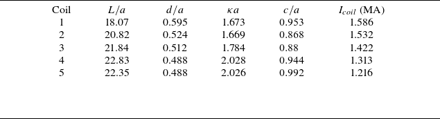
The geometrical properties of each coil relevant for an engineering design are listed in table 1.
Normalised coil length ( $L/a$
), inter-coil clearance (
$L/a$
), inter-coil clearance ( $d/a$
), maximum coil curvature (
$d/a$
), maximum coil curvature ( $\kappa a$
), coil–plasma clearance (
$\kappa a$
), coil–plasma clearance ( $c/a$
) and current (
$c/a$
) and current ( $I_{coil}$
) for each coil of the coilset presented in this work. Here,
$I_{coil}$
) for each coil of the coilset presented in this work. Here, $a$
is the minor radius of the underlying VMEC equilibrium.
$a$
is the minor radius of the underlying VMEC equilibrium.

This coilset results in sufficiently low field errors to preserve the fast-particle confinement expected from the target equilibrium. The coils in Wendelstein 7-X have $L/a\sim 16$
,
$L/a\sim 16$
, $d/a\sim 0.7$
,
$d/a\sim 0.7$
, $\kappa a\sim 1.3$
and
$\kappa a\sim 1.3$
and $c/a\sim 0.55$
, but create significantly larger field errors than this coilset. Nonetheless, one may worry that construction may be hindered by the complexity of these coils, as was already the case in W7-X (Klinger et al. Reference Klinger2013). One may speculate that, if built at a larger size than W7-X using modern engineering capabilities, these limitations may be mitigated, but this is unclear. Therefore, one may desire better
$c/a\sim 0.55$
, but create significantly larger field errors than this coilset. Nonetheless, one may worry that construction may be hindered by the complexity of these coils, as was already the case in W7-X (Klinger et al. Reference Klinger2013). One may speculate that, if built at a larger size than W7-X using modern engineering capabilities, these limitations may be mitigated, but this is unclear. Therefore, one may desire better $L_{\boldsymbol{\nabla }B}^*$
in future optimised configurations.
$L_{\boldsymbol{\nabla }B}^*$
in future optimised configurations.
3.2. The QI properties
To confirm the QI quality of this configuration, we first present several qualitative results. First, the contours of constant magnetic field strength $B$
, shown in figure 2 appear to have good QI quality, as can be seen in the top plots of figure 2. Some deviation from perfect QI around the field maximum is also observed. The excellent alignment of both the field maxima and minima in the rightmost plots of this same figure show that these features are minor.
$B$
, shown in figure 2 appear to have good QI quality, as can be seen in the top plots of figure 2. Some deviation from perfect QI around the field maximum is also observed. The excellent alignment of both the field maxima and minima in the rightmost plots of this same figure show that these features are minor.


These deviations are generally caused by a slight coil ripple.
Given this excellent QI quality, we expect very small fast-ion losses, small neoclassical transport at low collisionality and small bootstrap current. We first use the SIMPLE code (Albert, Kasilov & Kernbichler Reference Albert, Kasilov and Kernbichler2020) to evaluate fast-ion losses in this configuration using a linear plasma pressure profile and at our canonical $\langle \beta \rangle =2\,\%$
. We simulated these 5000 collisionless particles isotropically on
$\langle \beta \rangle =2\,\%$
. We simulated these 5000 collisionless particles isotropically on $s=0.25$
(as is standard practice in this type of calculation, see e.g. Landreman & Paul (Reference Landreman and Paul2022)), for all design points listed in table 3. These particles were simulated for 0.2 s, the typical slowing-down time of such particles in a fusion-relevant plasma Landreman & Paul (Reference Landreman and Paul2022). At all chosen design points, zero fast particles were found to be lost.
$s=0.25$
(as is standard practice in this type of calculation, see e.g. Landreman & Paul (Reference Landreman and Paul2022)), for all design points listed in table 3. These particles were simulated for 0.2 s, the typical slowing-down time of such particles in a fusion-relevant plasma Landreman & Paul (Reference Landreman and Paul2022). At all chosen design points, zero fast particles were found to be lost.
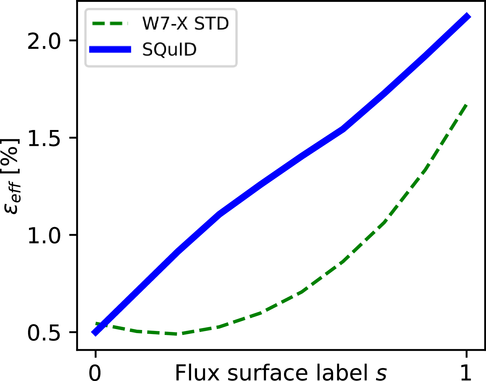
Next, we use the NEO code (Nemov et al. Reference Nemov, Kasilov, Kernbichler and Heyn1999) to calculate $\varepsilon _{\textrm {eff}}$
, which parameterises the neoclassical transport magnitude at low particle collisionality. In figure 3, we compare
$\varepsilon _{\textrm {eff}}$
, which parameterises the neoclassical transport magnitude at low particle collisionality. In figure 3, we compare $\varepsilon _{\textrm {eff}}$
in this SQuID with that of the W7-X standard (STD) configuration, which is smaller than necessary for a viable fusion reactor, and has the lowest
$\varepsilon _{\textrm {eff}}$
in this SQuID with that of the W7-X standard (STD) configuration, which is smaller than necessary for a viable fusion reactor, and has the lowest $\varepsilon _{\textrm {eff}}$
of all W7-X’s reference configurations. We see that this SQuID has slightly higher
$\varepsilon _{\textrm {eff}}$
of all W7-X’s reference configurations. We see that this SQuID has slightly higher $\varepsilon _{\textrm {eff}}$
than the W7-X STD (a property beneficial to its electron root, discussed in § 3.3), but it remains sufficiently low to be considered acceptable in a fusion power plant (Beidler et al. Reference Beidler2021). This can be seen in the analysis performed in § 3.5.
$\varepsilon _{\textrm {eff}}$
than the W7-X STD (a property beneficial to its electron root, discussed in § 3.3), but it remains sufficiently low to be considered acceptable in a fusion power plant (Beidler et al. Reference Beidler2021). This can be seen in the analysis performed in § 3.5.
The radial dependence of $\varepsilon _{\textrm {eff}}$
as a function of the flux surface label
$\varepsilon _{\textrm {eff}}$
as a function of the flux surface label $s$
for the novel SQuID presented in this work, and for the W7-X standard configuration.
$s$
for the novel SQuID presented in this work, and for the W7-X standard configuration.

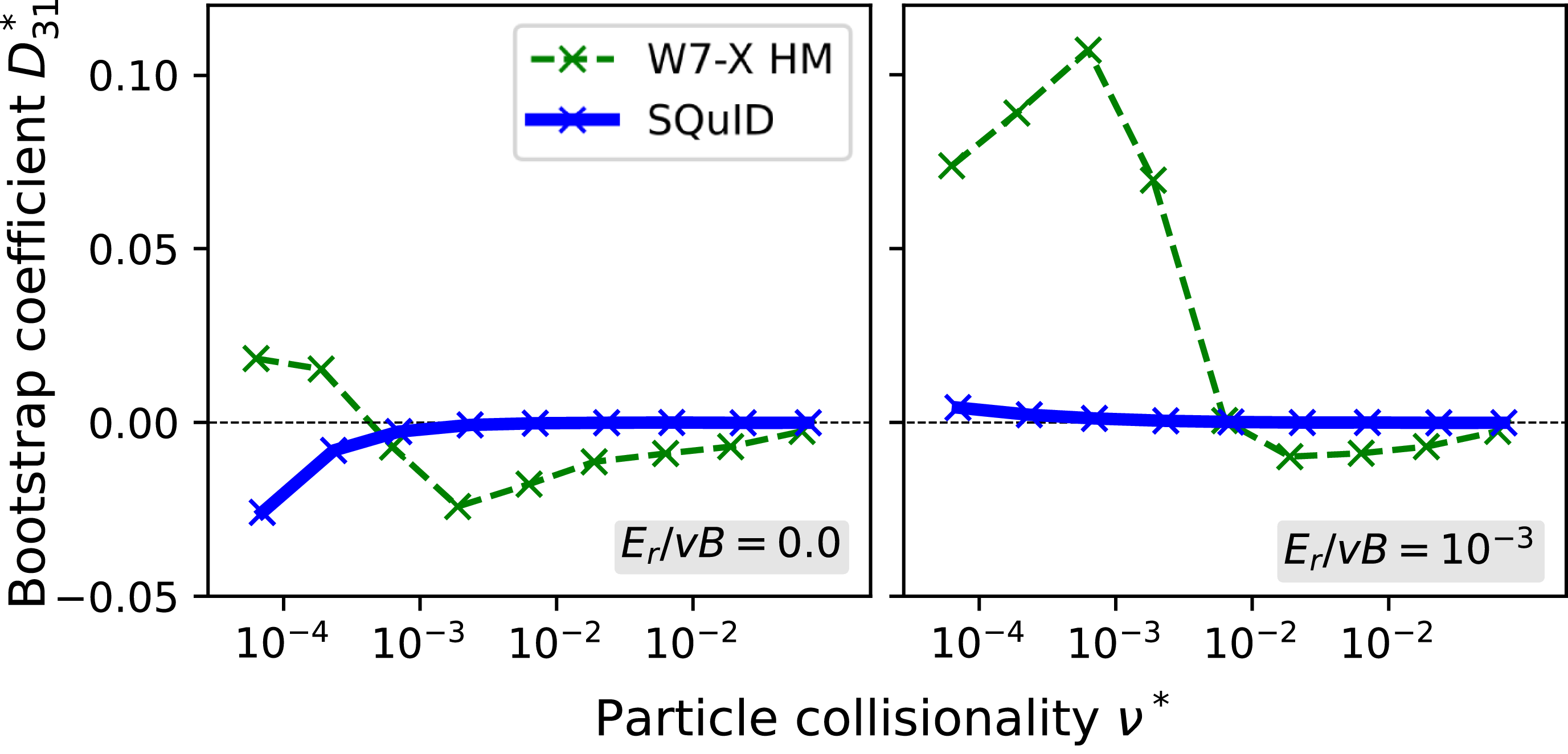
We next quantify the toroidal bootstrap current in this SQuID. To do this, we first calculate the monoenergetic bootstrap current coefficient $D_{31}^*$
(Beidler et al. Reference Beidler2011) for various particle collisionalities
$D_{31}^*$
(Beidler et al. Reference Beidler2011) for various particle collisionalities $\nu ^* = R_{maj}\nu /(\iota v)$
, where
$\nu ^* = R_{maj}\nu /(\iota v)$
, where $R_{maj}$
is the major radius of the torus and
$R_{maj}$
is the major radius of the torus and $v$
is the particle velocity. For reference, we compare this quantity against the W7-X high mirror (HM) configuration in figure 4, which has the lowest bootstrap current of all the W7-X variants. We find extremely low toroidal bootstrap currents with magnitudes of around 15 kA over a range of plasma profiles when scaled to a reactor design point, as can be seen in table 2. Such small net toroidal currents are not expected to significantly alter the plasma equilibrium, and therefore should benefit the robust operation of an island divertor concept, discussed more in § 3.6. This also renders this design effectively immune to current-driven instabilities and disruptions. Therefore, we expect the bootstrap current in this equilibrium to be within a reactor-relevant range. By comparison, Wendelstein 7-X has a roughly 350 kA bootstrap current.
$v$
is the particle velocity. For reference, we compare this quantity against the W7-X high mirror (HM) configuration in figure 4, which has the lowest bootstrap current of all the W7-X variants. We find extremely low toroidal bootstrap currents with magnitudes of around 15 kA over a range of plasma profiles when scaled to a reactor design point, as can be seen in table 2. Such small net toroidal currents are not expected to significantly alter the plasma equilibrium, and therefore should benefit the robust operation of an island divertor concept, discussed more in § 3.6. This also renders this design effectively immune to current-driven instabilities and disruptions. Therefore, we expect the bootstrap current in this equilibrium to be within a reactor-relevant range. By comparison, Wendelstein 7-X has a roughly 350 kA bootstrap current.
The monoenergetic bootstrap current coefficient $D_{31}^*$
for this novel SQuID (with coil ripple) and for the W7-X HM configuration (without coil ripple) at
$D_{31}^*$
for this novel SQuID (with coil ripple) and for the W7-X HM configuration (without coil ripple) at $s=0.25$
, as a function of particle collisionality
$s=0.25$
, as a function of particle collisionality $\nu ^*$
, for two values of the normalised radial electric field
$\nu ^*$
, for two values of the normalised radial electric field $E_r/v B$
. These values are of relevance for electrons (left) and ions (right).
$E_r/v B$
. These values are of relevance for electrons (left) and ions (right).

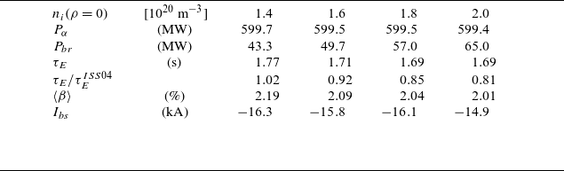
Global results for the density scan in the optimised configuration scaled to a plasma volume of 1450 m $^3$
. The central ion densities of individual cases, with
$^3$
. The central ion densities of individual cases, with $n^{\textrm {D}}=n^{\textrm {T}}=n_i/2$
, appear in the first row. Heating power provided by
$n^{\textrm {D}}=n^{\textrm {T}}=n_i/2$
, appear in the first row. Heating power provided by $\alpha$
-particles,
$\alpha$
-particles, $P_\alpha$
, bremsstrahlung losses,
$P_\alpha$
, bremsstrahlung losses, $P_{br}$
, the associated energy confinement times,
$P_{br}$
, the associated energy confinement times, $\tau _E$
(given in seconds and as a multiple of the ISS04 scaling), the volume-averaged plasma pressure,
$\tau _E$
(given in seconds and as a multiple of the ISS04 scaling), the volume-averaged plasma pressure, $\langle \beta \rangle$
, and the total bootstrap current are listed for each simulation.
$\langle \beta \rangle$
, and the total bootstrap current are listed for each simulation.

3.3. Electron root
To model reactor plasmas, in this subsection we scale the optimised equilibrium to a volume of 1450 m $^3$
, yielding a major radius of
$^3$
, yielding a major radius of $R=20.13$
m and a minor radius of
$R=20.13$
m and a minor radius of $a=1.91$
m. The average magnetic field strength at the plasma axis was taken to be
$a=1.91$
m. The average magnetic field strength at the plasma axis was taken to be $B_0=7.5$
T. Other sizes and field strengths are considered in § 3.5. This size was chosen here to be consistent with the work presented in Beidler et al. (Reference Beidler, Drevlak, Geiger, Helander, Smith and Turkin2024), which is reasonably close to the ‘medium reactor’ design point in table 3.
$B_0=7.5$
T. Other sizes and field strengths are considered in § 3.5. This size was chosen here to be consistent with the work presented in Beidler et al. (Reference Beidler, Drevlak, Geiger, Helander, Smith and Turkin2024), which is reasonably close to the ‘medium reactor’ design point in table 3.
We used the one-dimensional transport code NTSS (Turkin et al. Reference Turkin, Beidler, Maaßberg, Murakami, Tribaldos and Wakasa2011) to perform transport simulations on this configuration, scanning through core plasma densities of deuterium and tritium while keeping the profile shape fixed. NTSS then solves the coupled energy balance equations for electrons ( $\sigma =e$
), deuterium (
$\sigma =e$
), deuterium ( $\sigma =\textrm {D}$
), tritium (
$\sigma =\textrm {D}$
), tritium ( $\sigma =\textrm {T}$
) and helium ash (
$\sigma =\textrm {T}$
) and helium ash ( $\sigma =\textrm {He}$
), modelling the energy flux densities as the sum of neoclassical and anomalous contributions,
$\sigma =\textrm {He}$
), modelling the energy flux densities as the sum of neoclassical and anomalous contributions, $Q^\sigma = Q^\sigma _{\textrm {neo}} + Q^\sigma _{\textrm {anom}}$
.
$Q^\sigma = Q^\sigma _{\textrm {neo}} + Q^\sigma _{\textrm {anom}}$
.
The neoclassical portion is determined using tabulated values of the mono-energetic transport coefficients calculated by the drift kinetic equation solver DKES (van Rij & Hirshman Reference van Rij and Hirshman1989), while the anomalous portion is modelled by the simple formula $Q^\sigma _{\textrm {anom}} = -n^\sigma \chi _{\textrm {anom}} (\textrm {d}T^\sigma /\textrm {d}r)$
with the magnitude of diffusion coefficient
$Q^\sigma _{\textrm {anom}} = -n^\sigma \chi _{\textrm {anom}} (\textrm {d}T^\sigma /\textrm {d}r)$
with the magnitude of diffusion coefficient $\chi _{\textrm {anom}}$
being adjusted during the course of the density scan to yield fusion plasmas producing
$\chi _{\textrm {anom}}$
being adjusted during the course of the density scan to yield fusion plasmas producing $P_\alpha = 600$
MW of alpha-particle heating power. The profile of the radial electric field is simultaneously calculated, with the particle flux densities also being modelled as a sum of neoclassical and anomalous (turbulent) contributions,
$P_\alpha = 600$
MW of alpha-particle heating power. The profile of the radial electric field is simultaneously calculated, with the particle flux densities also being modelled as a sum of neoclassical and anomalous (turbulent) contributions, $\varGamma ^\sigma = \varGamma ^\sigma _{\textrm {neo}} + \varGamma ^\sigma _{\textrm {anom}}$
. The neoclassical portion can again be calculated from the DKES data set, and the anomalous portion is obtained from
$\varGamma ^\sigma = \varGamma ^\sigma _{\textrm {neo}} + \varGamma ^\sigma _{\textrm {anom}}$
. The neoclassical portion can again be calculated from the DKES data set, and the anomalous portion is obtained from $\varGamma ^\sigma _{\textrm {anom}}=- D_{\textrm {anom}} (\textrm {d}n^\sigma /\textrm {d}r)$
, with the additional assumption that the ratio of diffusion coefficients
$\varGamma ^\sigma _{\textrm {anom}}=- D_{\textrm {anom}} (\textrm {d}n^\sigma /\textrm {d}r)$
, with the additional assumption that the ratio of diffusion coefficients $\chi _{\textrm {anom}}/D_{\textrm {anom}} = 7.5$
. A differential equation is solved for the radial electric field to ensure a unique value of
$\chi _{\textrm {anom}}/D_{\textrm {anom}} = 7.5$
. A differential equation is solved for the radial electric field to ensure a unique value of $E_r$
in portions of the plasma where multiple roots of the ambipolarity constraint exist. This equation serves to minimise the generalised heat production rate, thereby introducing thermodynamic considerations into the determination of the radius at which root transitions take place (Shaing Reference Shaing1984; Turkin et al. Reference Turkin, Beidler, Maaßberg, Murakami, Tribaldos and Wakasa2011).
$E_r$
in portions of the plasma where multiple roots of the ambipolarity constraint exist. This equation serves to minimise the generalised heat production rate, thereby introducing thermodynamic considerations into the determination of the radius at which root transitions take place (Shaing Reference Shaing1984; Turkin et al. Reference Turkin, Beidler, Maaßberg, Murakami, Tribaldos and Wakasa2011).
Device characteristics according to transport analysis.

The tabulated results of this density scan for global quantities of relevance are shown in table 2. In addition to $P_\alpha$
, the total bremsstrahlung losses,
$P_\alpha$
, the total bremsstrahlung losses, $P_{br}$
, are also given, as the energy confinement time,
$P_{br}$
, are also given, as the energy confinement time, $\tau _E$
, has been calculated from the ratio of stored plasma energy to the ‘net’ heating power,
$\tau _E$
, has been calculated from the ratio of stored plasma energy to the ‘net’ heating power, $P_\alpha - P_{br}$
. As would be expected,
$P_\alpha - P_{br}$
. As would be expected, $\tau _E$
remains nearly constant throughout the scan, having a value which increasingly exceeds that expected from the International Stellarator Scaling ISS04 (Yamada et al. Reference Yamada2005) as the density rises. The radial extent of the electron root decreases with increasing density, as the comparison of the
$\tau _E$
remains nearly constant throughout the scan, having a value which increasingly exceeds that expected from the International Stellarator Scaling ISS04 (Yamada et al. Reference Yamada2005) as the density rises. The radial extent of the electron root decreases with increasing density, as the comparison of the $E_r$
profiles from the four simulations in figure 5 shows. This is in accordance with theoretical expectations, and the electron root will ultimately disappear if the density is increased further. The total bootstrap current values remain nearly unaffected by the density variation, and are small enough to have no discernible influence on the rotational transform profile.
$E_r$
profiles from the four simulations in figure 5 shows. This is in accordance with theoretical expectations, and the electron root will ultimately disappear if the density is increased further. The total bootstrap current values remain nearly unaffected by the density variation, and are small enough to have no discernible influence on the rotational transform profile.
The radial electric field $E_r$
as a function of normalised plasma radius
$E_r$
as a function of normalised plasma radius $\rho$
for four different core ion densities. Here, a positive
$\rho$
for four different core ion densities. Here, a positive $E_r$
points towards the plasma boundary.
$E_r$
points towards the plasma boundary.

3.4. Magnetohydrodynamic stability
(left) Local ballooning-stability results for free-boundary equilibria using our optimised coilset and the profiles shown in the right frame. In the $(\iota , \langle \beta \rangle )$
plane, where
$(\iota , \langle \beta \rangle )$
plane, where $\iota$
is the rotational transform, the range of
$\iota$
is the rotational transform, the range of $\iota$
-values existing in the plasma is indicated (orange) as well as the region of local ballooning instability (grey). Red dashed lines mark locations of constant normalised minor radius,
$\iota$
-values existing in the plasma is indicated (orange) as well as the region of local ballooning instability (grey). Red dashed lines mark locations of constant normalised minor radius, $\rho$
; (right) Temperature (
$\rho$
; (right) Temperature ( $\mathrm{keV}$
, red) and density (
$\mathrm{keV}$
, red) and density ( $/(10^{19}\,\mathrm{m}^{3}$
)) profiles.
$/(10^{19}\,\mathrm{m}^{3}$
)) profiles.

We used the VMEC equilibrium code in its free-boundary version to calculate finite-pressure equilibria sustained by the magnetic field generated by our coilset. The respective equilibrium pressure profile, which is defined by the temperature and density profiles shown in the right frame of figure 6, has a peaking factor of $\beta _{\mathrm{axis}}/\langle \beta \rangle \approx 3.5$
, as opposed to a value of
$\beta _{\mathrm{axis}}/\langle \beta \rangle \approx 3.5$
, as opposed to a value of ${\approx}2$
for
${\approx}2$
for $p\propto (1-\rho ^2)$
. As shown in the left frame of figure 6, we observe that the shear,
$p\propto (1-\rho ^2)$
. As shown in the left frame of figure 6, we observe that the shear, $\mathrm{d}\iota / \mathrm{d}\rho$
, increases with plasma-
$\mathrm{d}\iota / \mathrm{d}\rho$
, increases with plasma- $\beta$
. While the edge value of the rotational transform changes only little, its axis value decreases substantially, but stays above the low-order natural rational
$\beta$
. While the edge value of the rotational transform changes only little, its axis value decreases substantially, but stays above the low-order natural rational $\iota =4/5$
for the envisaged design point of
$\iota =4/5$
for the envisaged design point of $\langle \beta \rangle =0.02$
with a safe margin. For plasma pressures up to
$\langle \beta \rangle =0.02$
with a safe margin. For plasma pressures up to $\langle \beta \rangle \approx 0.04$
, we solved the ideal-MHD ballooning equation along field lines (Correa-Restrepo Reference Correa-Restrepo1978; Nührenberg & Zille, Reference Nührenberg and Zille1988), which gives a more stringent statement of local stability than Mercier’s criterion (Mercier Reference Mercier1962). The integration of the ballooning equation on closed field lines with high-order rational rotational transform guarantees that no unstable region is missed. For
$\langle \beta \rangle \approx 0.04$
, we solved the ideal-MHD ballooning equation along field lines (Correa-Restrepo Reference Correa-Restrepo1978; Nührenberg & Zille, Reference Nührenberg and Zille1988), which gives a more stringent statement of local stability than Mercier’s criterion (Mercier Reference Mercier1962). The integration of the ballooning equation on closed field lines with high-order rational rotational transform guarantees that no unstable region is missed. For $\langle \beta \rangle \lesssim 0.03$
, stability prevails across the entire minor radius.
$\langle \beta \rangle \lesssim 0.03$
, stability prevails across the entire minor radius.
Plasma profiles. Assumed shape of density profile (top left), which is re-scaled for each device scenario. Steady-state temperature profiles (keV) of small-scale ‘burning experiment’ (top right) and small/medium reactor-scale devices (bottom left/right). Dashed lines give the result obtained when neglecting neoclassical transport.

3.5. Transport and confinement
The SQuIDs are optimised to reduce both neoclassical and turbulent transport. Here, we perform a set of simulations for these transport channels separately and sum them together, as theoretically justified under the assumption of scale separation between fluctuations and the equilibrium geometry (Abel et al. Reference Abel, Plunk, Wang, Barnes, Cowley, Dorland and Schekochihin2013), to obtain an overall assessment of the improvements achieved in global confinement.
We simulate the turbulence using the GX code (Mandell et al. Reference Mandell, Hakim, Hammett and Francisquez2020, Reference Mandell, Dorland, Abel, Gaur, Kim, Martin and Qian2022), at five radial locations, and the solution of the heat transport equation is performed using the Neotransp code, which includes neoclassical fluxes, calculated using mono-energetic coefficients from DKES, and a general model of turbulent heat flux, set with the gyrokinetic simulation data. Although the ion and electron species are both treated kinetically, the temperatures of these species are set equal, based on the assumption of strong thermal coupling. The density profile has a fixed prescribed shape; see figure 7. There is therefore only a single transport equation to solve, whose steady-state solution yields the temperature profile $T(\rho )$
 \begin{equation} \left (\frac {\textrm {d}V}{\textrm {d}\rho }\right )^{-1}\frac {\textrm {d}}{\textrm {d}\rho }\left ( \frac {\textrm {d}V}{\textrm {d}\rho } \sum _a \big\langle \big(Q_a^{\mathrm{GK}} + Q_a^{\mathrm{NC}}\big)\boldsymbol{\cdot }\boldsymbol{\nabla }\rho \big\rangle _\psi \right ) = P_\alpha + P_{\mathrm{ext}} \end{equation}
where $V(\rho )$
is the volume,
$V(\rho )$
is the volume, $\rho = \sqrt {s}$
,
$\rho = \sqrt {s}$
, $P_\alpha$
and
$P_\alpha$
and $P_{\mathrm{ext}}$
are internal (
$P_{\mathrm{ext}}$
are internal ( $\alpha$
particle) and external (heating) power densities,
$\alpha$
particle) and external (heating) power densities, $Q_a^{\mathrm{NC}}$
and
$Q_a^{\mathrm{NC}}$
and $Q_a^{\mathrm{GK}}$
are the neoclassical and turbulent heat fluxes for species
$Q_a^{\mathrm{GK}}$
are the neoclassical and turbulent heat fluxes for species $a$
and
$a$
and $\langle \cdot\rangle _\psi$
is a flux surface average over the magnetic surface labelled by
$\langle \cdot\rangle _\psi$
is a flux surface average over the magnetic surface labelled by $\rho$
. The boundary condition to the transport equation, which strongly affects overall confinement, is taken to be
$\rho$
. The boundary condition to the transport equation, which strongly affects overall confinement, is taken to be $-T'/T \equiv a_\textrm{min}/L_T = 5.6$
at
$-T'/T \equiv a_\textrm{min}/L_T = 5.6$
at $\rho = 0.7$
. This choice yields a reasonable confinement time as compared with ISS04 scaling Yamada et al. (Reference Yamada2005) for a
$\rho = 0.7$
. This choice yields a reasonable confinement time as compared with ISS04 scaling Yamada et al. (Reference Yamada2005) for a $20$
MW heating scenario (
$20$
MW heating scenario ( $P_\alpha$
set to zero) using the W7X standard configuration. As shown in table 3, the same boundary condition and heating set-up for the SQuIDs gives an estimate of the expected relative improvement of the renormalisation factor in corresponding devices.
$P_\alpha$
set to zero) using the W7X standard configuration. As shown in table 3, the same boundary condition and heating set-up for the SQuIDs gives an estimate of the expected relative improvement of the renormalisation factor in corresponding devices.
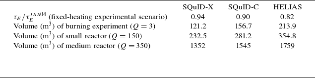
Based on this set-up, we explore three device scenarios, comparing performance of a scaled-up version of W7X-STD configuration, which we denote ‘HELIAS’, and two SQuID configurations, one presented here (‘SQuID-C’), and the one published in Goodman et al. (Reference Goodman, Xanthopoulos, Plunk, Smith, Nührenberg, Beidler, Henneberg, Roberg-Clark, Drevlak and Helander2024) (‘SQUID-X’). For these scenarios, we include an ‘effective’ alpha heating ( $P_\alpha$
), i.e. that obtained if the ions were taken to be a 50/50 mixture of deuterium and tritium.
$P_\alpha$
), i.e. that obtained if the ions were taken to be a 50/50 mixture of deuterium and tritium.
The first device scenario corresponds to a modestly sized machine aimed at achieving a slightly better than break-even fusion gain of $Q = 3$
. The second scenario is a larger device that could serve as a small fusion power plant with
$Q = 3$
. The second scenario is a larger device that could serve as a small fusion power plant with $1.5$
GW of total fusion power and a fusion gain of
$1.5$
GW of total fusion power and a fusion gain of $Q = 150$
. The third device is a more conventionally scaled design that could achieve about
$Q = 150$
. The third device is a more conventionally scaled design that could achieve about $3.5$
GW of total fusion power. This final scenario is chosen to be similar in scale to what has been assumed for the coil design, electron-root calculations and divertor concept.
$3.5$
GW of total fusion power. This final scenario is chosen to be similar in scale to what has been assumed for the coil design, electron-root calculations and divertor concept.
For each of these device scenarios we solve the transport equations for steady-state profiles, taking into account effective power input by fusion-born alpha particles. The central densities for these scenarios are scaled to be $3.0 \times 10^{20}$
,
$3.0 \times 10^{20}$
, $3.7 \times 10^{20}$
and
$3.7 \times 10^{20}$
and $1.5 \times 10^{20}\textrm { m}^{-3}$
, respectively. The volume-averaged field strengths are assumed to be
$1.5 \times 10^{20}\textrm { m}^{-3}$
, respectively. The volume-averaged field strengths are assumed to be $8$
,
$8$
, $9$
and
$9$
and $7.5\textrm { T}$
. Note that, for the profiles obtained, the volume-averaged values of
$7.5\textrm { T}$
. Note that, for the profiles obtained, the volume-averaged values of $\beta$
are in the range of
$\beta$
are in the range of $1{-}2\,\%$
. The volumes of each configuration are adjusted to obtain the target performance, as implied by the steady profiles. This gives an overall assessment of how the differences in confinement between these stellarator designs can affect the device design point, as the device volumes can be expected to shrink with improved confinement. Table 3 shows the resulting volumes for the three configurations for each device scenario, and figure 7 shows the steady-state temperature profiles. The SQuIDs – due to their reduced turbulence – achieve significantly smaller volumes, as expected, and also have higher core temperatures; this is because a greater power density is needed to achieve the target total fusion power at these lower volumes.
$1{-}2\,\%$
. The volumes of each configuration are adjusted to obtain the target performance, as implied by the steady profiles. This gives an overall assessment of how the differences in confinement between these stellarator designs can affect the device design point, as the device volumes can be expected to shrink with improved confinement. Table 3 shows the resulting volumes for the three configurations for each device scenario, and figure 7 shows the steady-state temperature profiles. The SQuIDs – due to their reduced turbulence – achieve significantly smaller volumes, as expected, and also have higher core temperatures; this is because a greater power density is needed to achieve the target total fusion power at these lower volumes.
3.6. Divertor concept
A stellarator reactor must have an acceptable exhaust solution, that is, the heat and particles escaping the confined plasma must meet certain requirements, such as not exceeding thermal limits on plasma-facing components (PFCs) and efficient removal of helium ash (Soboleva Reference Soboleva1997; Stangeby Reference Stangeby2000; Boozer Reference Boozer2015). Here, we demonstrate that the magnetic island chain at the edge is consistent with an island divertor (the same exhaust solution approach as that pursued by Wendelstein 7-X (Renner et al. Reference Renner, Sharma, Kisslinger, Boscary, Grote and Schneider2004)), by designing divertor plates which intersect the $\iota =1$
magnetic island chain present at the edge of the configuration. For this section, the configuration is scaled to the ‘medium reactor’ design point. A Poincaré plot showing the edge island chain is shown in figure 8. There are some additional edge structures visible (shown in orange) which are described in Davies et al. (Reference Davies, Drevlak, Feng, Geiger, Goodman, Smiet, Plunk, Xanthopoulos and Henneberg2025).
$\iota =1$
magnetic island chain present at the edge of the configuration. For this section, the configuration is scaled to the ‘medium reactor’ design point. A Poincaré plot showing the edge island chain is shown in figure 8. There are some additional edge structures visible (shown in orange) which are described in Davies et al. (Reference Davies, Drevlak, Feng, Geiger, Goodman, Smiet, Plunk, Xanthopoulos and Henneberg2025).
We employ the divertor plate design scheme developed by Davies et al. (Reference Davies, Feng, Boeyaert, Schmitt, Gerard, Garcia, Schmitz, Geiger and Henneberg2024), which results in divertor plates which catch and spread the non-radiated exhausted power in a localised region. The non-radiated power deposition on PFCs is modelled using the code EMC3-Lite (Feng et al. Reference Feng2022).
We employ a two-step approach to the design of these plates. Firstly, ‘vertical plates’ are created at a single toroidal location (approximately perpendicular to the magnetic field), and shaped to catch at least $90$
% of the diffusively transported energy. The toroidal and poloidal location of the vertical plates are selected to minimise the parallel power load
$90$
% of the diffusively transported energy. The toroidal and poloidal location of the vertical plates are selected to minimise the parallel power load $Q_\parallel$
(that is, the power load divided by
$Q_\parallel$
(that is, the power load divided by $\sin (\theta _i)$
, where
$\sin (\theta _i)$
, where $\theta _i$
is the incidence angle of the magnetic field on the PFCs). Secondly, PFC power loads are reduced below
$\theta _i$
is the incidence angle of the magnetic field on the PFCs). Secondly, PFC power loads are reduced below $10$
MW m–
$10$
MW m– ${}^2$
by toroidally ‘stretching’ the plates along the magnetic field (extending the plates toroidally while still intersecting the same magnetic flux tubes), thereby reducing the incidence angle and increasing the PFC area wetted by the power.
${}^2$
by toroidally ‘stretching’ the plates along the magnetic field (extending the plates toroidally while still intersecting the same magnetic flux tubes), thereby reducing the incidence angle and increasing the PFC area wetted by the power. $Q_\parallel$
determines the amount of ‘stretching’ required.
$Q_\parallel$
determines the amount of ‘stretching’ required.
Poincaré section of the configuration with core $\beta =8\,\%$
at two (up–down symmetric) toroidal locations. An
$\beta =8\,\%$
at two (up–down symmetric) toroidal locations. An $\iota =1$
island chain with toroidal and poloidal periodicities
$\iota =1$
island chain with toroidal and poloidal periodicities $m=n=4$
(blue) and additional ‘tentacle’ structures (orange) are visible at the edge. An indicative vessel wall shown in red.
$m=n=4$
(blue) and additional ‘tentacle’ structures (orange) are visible at the edge. An indicative vessel wall shown in red.

Three-dimensional plot of divertor plates. Left: top–down view; right: side-on view for one half-field period. Last closed flux surface shown in cyan and divertor plates outlined in blue and orange.

(upper) Power deposition on plasma-facing components (divertor plates and approximate location of vessel wall) in a single field period, as a function of toroidal angle $\phi$
and poloidal angle
$\phi$
and poloidal angle $\theta$
, for
$\theta$
, for $T=200$
eV and
$T=200$
eV and $\chi =1$
m
$\chi =1$
m ${}^2$
s−1. Divertor plates outlined in blue and orange; (lower left) zoom-in of upper plot; (lower right) incidence angle of magnetic field on divertor plate (zoomed in).
${}^2$
s−1. Divertor plates outlined in blue and orange; (lower left) zoom-in of upper plot; (lower right) incidence angle of magnetic field on divertor plate (zoomed in).

The physical parameters required for this workflow are as follows.
-
(i) The magnetic geometry, for which we use the magnetic geometry corresponding to core $\beta$
of 8 %, as this is the most relevant from a reactor perspective.
$\beta$
of 8 %, as this is the most relevant from a reactor perspective. -
(ii) The net (non-radiated) power exiting the confined region. We assume
$60$
MW, consistent with (for example)
$3$
GW fusion power (
$600$
MW
$\alpha$
power), with
$0$
% radiated power in the core and a 90 % radiated in the edge. The need for a high radiated fraction for power exhaust management in a power plant has been highlighted previously (e.g. Feng Reference Feng2013). Wendelstein 7-X is able to operate in detached conditions, in which the radiated power fraction is
$80\,\%$
or greater Jakubowski et al. (Reference Jakubowski2021), largely due to impurity radiation. Whether detachment can be achieved in reactor conditions and how best to realise this is an important area of ongoing research. -
(iii) The ratio of parallel-to-perpendicular diffusivity,
$(\kappa _{e0}T_{\text{LCFS}}^{5/2}/(n_e\chi ))$
, where
$\kappa _{e0}$
is a constant,
$T_{\text{LCFS}}$
the temperature at the last closed flux surface, used to set the (assumed constant) parallel diffusivity,
$n_e$
the (assumed constant) electron density and
$\chi$
a user-selected cross-field diffusive transport coefficient. There is currently a large uncertainty in
$T_{\text{LCFS}}$
,
$n_e$
and
$\chi$
; the approach we take here therefore is to design plates consistent with a range of values. The plates presented here are designed to be consistent with two values of the ratio
$(\kappa _{e0}T_{\text{LCFS}}^{5/2}/(n_e\chi ))$
; a lower value corresponding to (
$T_{\text{LCFS}}=100$
eV,
$n_e=10^{19}$
m
${}^{-3}$
$\chi =3$
m
${}^2$
s−1) and a higher value corresponding to (
$T_{\text{LCFS}}=200$
eV,
$n_e=10^{19}$
m
${}^{-3}$
$\chi =1$
m
${}^2$
s−1). Our plates are able to catch and spread the power acceptably for both cases, despite the parallel-to-perpendicular diffusivity ratio varying by a factor of 17.


The divertor plates are shown in figure 9; the plates are located on the outboard side of the stellarator and are ‘centred’ about the $\phi =45^\circ$
cross-section, which is the up–down symmetric plane in the straight sections of the device. The plates are stellarator symmetric by design.
$\phi =45^\circ$
cross-section, which is the up–down symmetric plane in the straight sections of the device. The plates are stellarator symmetric by design.
The outline of the plates in $(\phi , \theta )$
over one field period, where
$(\phi , \theta )$
over one field period, where $\theta =\arctan ((Z-Z_{ma})/(R-R_{ma}))$
is the geometric poloidal angle with respect to the magnetic axis located at
$\theta =\arctan ((Z-Z_{ma})/(R-R_{ma}))$
is the geometric poloidal angle with respect to the magnetic axis located at $(R_{ma}(\phi ), Z_{ma}(\phi ))$
, is shown in figure 10, upper. This also shows the simulated PFC power deposition using the high parallel-to-perpendicular diffusion, and we zoom in to the most heat-catching plate in figure 10, lower left. The fraction of power caught on the plates is
$(R_{ma}(\phi ), Z_{ma}(\phi ))$
, is shown in figure 10, upper. This also shows the simulated PFC power deposition using the high parallel-to-perpendicular diffusion, and we zoom in to the most heat-catching plate in figure 10, lower left. The fraction of power caught on the plates is $95\,\%$
for the lower of parallel-to-perpendicular diffusivity ratio (
$95\,\%$
for the lower of parallel-to-perpendicular diffusivity ratio ( $T=100$
eV,
$T=100$
eV, $\chi =3$
m
$\chi =3$
m ${}^2$
s−1) and
${}^2$
s−1) and $96\,\%$
for the higher ratio (
$96\,\%$
for the higher ratio ( $T=200$
eV,
$T=200$
eV, $\chi =1$
m
$\chi =1$
m ${}^2$
s−1). The peak power deposition on the plates are
${}^2$
s−1). The peak power deposition on the plates are $4$
and
$4$
and $9$
MW m−2 respectively.
$9$
MW m−2 respectively.
The plate ‘tilting’ (i.e. projecting points on the plate toroidally) determines the toroidal extent of the plate and the incidence angle $\theta _i$
; the latter is shown in figure 10, lower right. Our plate is defined by a logically rectangular grid of points. The projection in
$\theta _i$
; the latter is shown in figure 10, lower right. Our plate is defined by a logically rectangular grid of points. The projection in $\phi$
is set for each row of points, such that all points in a row are projected by the same angular distance (see Davies et al. (Reference Davies, Feng, Boeyaert, Schmitt, Gerard, Garcia, Schmitz, Geiger and Henneberg2024) for more detail). Figure 10, lower right, shows that the incidence angle can become small (below
$\phi$
is set for each row of points, such that all points in a row are projected by the same angular distance (see Davies et al. (Reference Davies, Feng, Boeyaert, Schmitt, Gerard, Garcia, Schmitz, Geiger and Henneberg2024) for more detail). Figure 10, lower right, shows that the incidence angle can become small (below $3^\circ$
over most of the plate, and below
$3^\circ$
over most of the plate, and below $1^\circ$
in some locations) when this scheme is applied.
$1^\circ$
in some locations) when this scheme is applied.
4. Discussion
In this work, we have shown that MHD-stable stellarator plasmas can be designed having good energy and fast-ion confinement as well as minimal net toroidal currents, and a mechanism to help exhaust impurity ions from the plasma core. Through the use of the figure-of-merit found by Kappel et al. (Reference Kappel, Landreman and Malhotra2024), these plasmas can be created, to a high degree of fidelity, using a set of qualitatively sensible electromagnetic coils, which should permit the design of an island divertor. To our knowledge, the configuration presented in this work is the first of its kind, as it demonstrates that these properties can all be simultaneously achieved. As a result of these properties, configurations of its ilk are uniquely attractive as candidates for future fusion reactors and experiments. Better optimisation techniques and a better developed theoretical basis can likely improve on all of these properties, therefore yielding yet more attractive configurations. Further, there exist inconsistencies in this work (e.g. in the pressure profiles used throughout) that ought to be eliminated in a proper analysis, and future work should present its results all at a single (or a handful of) design points.
In the context of fusion reactors, this work requires several important caveats. These configurations are different from any stellarator ever built, and one might expect several unforeseen issues to hinder their promise in reality. Indeed, Wendelstein 7-X itself was initially conceived as a ‘fusion reactor candidate’ until subsequent experimental and theoretical study revealed certain shortcomings. Electromagnetic effects – which are expected to significantly increase turbulent transport in W7-X (Mulholland et al. Reference Mulholland, Aleynikova, Faber, Pueschel, Proll, Hegna, Terry and Nührenberg2023) − should be included in future optimisations and validations. Alfvénic activity (Alfvén Reference Alfvén1942), which may spoil fast-particle confinement and render these devices infeasible as fusion reactor candidates (White Reference White2022), is also still insufficiently explored theoretically (and experimentally) in SQuIDs. Another important caveat is the relatively unsophisticated physics model (i.e. anisotropic diffusion) used for the divertor design scheme. The use of simplified models for divertor plate design is relatively standard (e.g. Muldrew et al. Reference Muldrew, Warmer, Lion and Lux2021, Bader et al. Reference Bader2025; Lion et al. Reference Lion2025), but including more realistically the dynamics of radiation, impurities and neutral transport is likely to be important for qualifying divertor performance. Moreover, the exhaust solution must fulfil additional requirements, such as efficient helium removal, which are not considered here. Higher-fidelity tools, such as EMC3-Eirene (Feng et al. Reference Feng2014), are capable of more sophisticated edge modelling, but their computational cost and complexity make them currently unsuitable for automated PFC design. Finally, a proper, self-consistent treatment of the pressure profile in all calculations in this work is elusive, and likely requires the coupling of multiple codes (MHD, edge, core, neoclassical, etc.), which is a capability that has not been shown anywhere in the literature. These, and other physics phenomena that are not yet fully understood, may cause unforeseen challenges to reactor viability.
Accordingly, this configuration – and others like it – present many interesting questions for future scientific research. Does the neoclassically predicted electron root truly manifest, and, if so, how does it affect energy and particle confinement? What is the interplay between turbulence mitigation via the maximum- $\mathcal{J}$
property, the effect of expanded flux surfaces, and zonal flows? Do Alfvénic activity, electromagnetic turbulence or other unstudied phenomena render SQuIDs unsuitable for further study, or are they not of significant concern? Experimentally, it is unclear
$\mathcal{J}$
property, the effect of expanded flux surfaces, and zonal flows? Do Alfvénic activity, electromagnetic turbulence or other unstudied phenomena render SQuIDs unsuitable for further study, or are they not of significant concern? Experimentally, it is unclear $i.e.$
which heating/fuelling schemes will prove effective in SQuIDs, nor if the operational techniques being used in Wendelstein 7-X’s operation will need to be reconsidered. Indeed, the true test of such a configuration is its performance in a fusion-relevant regime, for a fusion-relevant time scale: a test which can only be done in a real stellarator experiment. Until their effectiveness under these conditions has been shown, a healthy dose of scepticism is needed for any fusion reactor candidates. That said, this design, and others like it, offer the opportunity to explore these questions both theoretically and experimentally.
$i.e.$
which heating/fuelling schemes will prove effective in SQuIDs, nor if the operational techniques being used in Wendelstein 7-X’s operation will need to be reconsidered. Indeed, the true test of such a configuration is its performance in a fusion-relevant regime, for a fusion-relevant time scale: a test which can only be done in a real stellarator experiment. Until their effectiveness under these conditions has been shown, a healthy dose of scepticism is needed for any fusion reactor candidates. That said, this design, and others like it, offer the opportunity to explore these questions both theoretically and experimentally.
Acknowledgements
Optimisations and simulations were performed with the Cobra and Raven HPCs (Garching) respectively. A.G. is supported by a grant from the Simons Foundation (560651). This work has been carried out within the framework of the EUROfusion Consortium, funded by the European Union via the Euratom Research and Training Programme (Grant Agreement No. 101052200 – EUROfusion). Views and opinions expressed are those of the author(s) only and do not necessarily reflect those of the European Union or the European Commission. Neither the European Union nor the European Commission can be held responsible for them.
Editor Peter Catto thanks the referees for their advice in evaluating this article.
Declaration of interests
The authors report no conflict of interest.


 Open access