





1 Introduction
Single-frequency fiber laser (SFFLs) are a kind of highly valued light source, providing narrow linewidth, low noise and compact all-fiber structure[ Reference Fu, Shi, Feng, Zhang, Yang, Xu, Zhu, Norwood and Peyghambarian 1 – Reference Poncelet, Lavit, Prakash, Dubé, Pierre, Guiraud, Traynor, Hilico and Santarelli 8 ]. Among these, ytterbium (Yb), erbium (Er) and thulium (Tm) systems have reached technological maturity, enabling a wide range of applications in the 1.0, 1.5 and 2.0 μm spectral windows, respectively. However, the demand for higher power levels and extended wavelength coverage continuously drives extensive researches into novel rare-earth-doped fibers and nonlinear conversion techniques[ Reference Fu, Li, Yu, Li, Li, Xiao, Gong and Yan 9 – Reference Tao, Jiang, Liu, Li, Zhou and Jiang 16 ]. In particular, the high-power SFFLs at 910 nm have attracted extensive interest for generating a 455 nm single-frequency (SF) blue laser through frequency doubling, which serves as an important laser source for high-state excitation transitions of cesium[ Reference Li, Zhao, Wei, Jin, Lu and Peng 17 ]. In addition, these high-performance SF blue lasers also enable applications such as laser cooling of atoms and underwater communication[ Reference Bartolacci, Laroche, Gilles, Girard, Robin and Cadier 18 – Reference Fang, Xu, Fu and Shi 26 ].
Significant progress has been witnessed in the past few years in the development of SF oscillators and corresponding high-gain Nd-doped fibers. Milliwatt-level output power at wavelengths including 871[ Reference AlYahyaei, Zhu, Norwood and Peyghambarian 20 ], 880[ Reference Fu, Zhu, Zong, Li, Chavez-Pirson, Norwood and Peyghambarian 21 ], 890[ Reference Wang, Chen, Wang, Yang, Sun, Wang, Zhang, Wang, Wen, Feng, Yu, Hu and Lvovich 22 ], 910[ Reference Liang, Fu, Sheng, Zhang, Zhang, Shi and Yao 23 ], 915[ Reference Fu, Zhu, Zong, Li, Zavala, Temyanko, Chavez-Pirson, Norwood and Peyghambarian 24 , Reference Zhu, Li, Ji, Li, Yang, Zhao, Wang and Zhang 25 ] and 930 nm[ Reference Fang, Xu, Fu and Shi 26 ] had been achieved using short distributed Bragg reflector (DBR) cavities. A 915 nm Nd-doped SFFL based on a ring cavity configuration was also reported recently[ Reference Jiang, Lan, Lan, Zhang, He, Xia and Luo 27 ]. The typical research progress of these SF oscillators is summarized in Figure 1. Among them, the 880 nm Nd-doped DBR SFFL developed by Fu et al. [ Reference Fu, Zhu, Zong, Li, Chavez-Pirson, Norwood and Peyghambarian 21 ], employing a heavily Nd-doped phosphate glass fiber, achieved an output power of 44.5 mW with a slope efficiency of 14.0%. Liang et al. [ Reference Liang, Fu, Sheng, Zhang, Zhang, Shi and Yao 23 ] recently demonstrated that a highly efficient 910 nm DBR SFFL can also be achieved using commercially available Nd-doped silica fiber (NDF) with an output power of 56.2 mW and a slope efficiency of 17.8%, which set a new record for the highest output power of an SF seed reported to date, even higher than that of seed sources fabricated by heavily Nd-doped phosphate fiber[ Reference AlYahyaei, Zhu, Norwood and Peyghambarian 20 , Reference Fu, Zhu, Zong, Li, Chavez-Pirson, Norwood and Peyghambarian 21 , Reference Fu, Zhu, Zong, Li, Zavala, Temyanko, Chavez-Pirson, Norwood and Peyghambarian 24 ]. However, while notable progress has been made in seed laser development, power scaling still remains a major challenge due to the strong competition between the 4F3/2–4I11/2 (~1060 nm) and the 4F3/2–4I9/2 (~900 nm) transitions[ Reference Laroche, Cadier, Gilles, Girard, Lablonde and Robin 28 ]. Generally, the approximately 1060 nm emission dominates in the competition process due to its four-level transition structure, often leading to parasitic lasing at approximately 1060 nm during amplification and consequently limiting approximately 900 nm power scaling. To mitigate this issue, various strategies – such as lowering fiber operating temperatures[ Reference Dawson, Drobshoff, Liao, Beach, Pennington and Payne 29 ], reducing the cladding-to-core ratio[ Reference Florentin, Corre, Robin, Barnini, Prakash, Santarelli, Gilles, Girard and Laroche 30 ] and designing specialized wavelength-selective waveguides[ Reference Pax, Khitrov, Drachenberg, Allen, Ward, Dubinskii, Messerly and Dawson 31 – Reference Bufetov, Dudin, Shubin, Senatorov, Dianov, Grudinin, Goncharov, Zalevskii, Gur'yanov, Yashkov, Umnikov and Vechkanov 33 ] – have been proposed and explored to improve the approximately 900 nm power scaling in the past few years. For instance, in 2004, an 11 W Nd-doped fiber laser at 938 nm was demonstrated by cooling the Nd-doped fiber via liquid nitrogen for transforming the three-level transition into quasi-four-level transition[ Reference Dawson, Beach, Drobshoff, Liao, Pennington, Payne, Taylor, Hackenberg and Bonaccini 34 ]. In 2013, a 20 W CW laser output at 915 nm was realized in Nd-doped fibers with a core/cladding diameter of 20/80 μm[ Reference Laroche, Cadier, Gilles, Girard, Lablonde and Robin 28 ]. In 2016, the use of photonic crystal fibers in Nd-doped lasers effectively suppressed the four-level transitions at 1.06 μm and supported a 27 W ~900 nm laser output[ Reference Pax, Khitrov, Drachenberg, Allen, Ward, Dubinskii, Messerly and Dawson 31 ]. In 2023, an 83 W laser power was further obtained from 30/125 μm NDF[ Reference Le Corre, Gilles, Girard, Barnini, Kervella, Guitton, Cadier, Robin, Santarelli and Larochel 35 ]. While the existing approaches have made significant progress in improving the power at ~900 nm, the reported lasers are not linearly polarized SFFLs. As summarized in Figure 1, the highest reported power of all-fiber SFFLs in this spectral region to date remains below 3 W[ Reference Prakash, Darwich, Dixneuf, Guiraud, Traynor, Corre, Robin, Florentin, Laroche, Bertoldi, Santarelli and Hilico 36 , Reference Rota-Rodrigo, Gouhier, Laroche, Zhao, Canuel, Bertoldi, Bouyer, Traynor, Cadier, Robin and Santarelli 37 ].
Typical research progress of Nd-doped SFFLs from 870 to 940 nm.

In recent years, our group has attempted to delve into the intrinsic properties of Nd-doped glass fibers and conducted in-depth research on the luminescence characteristics and microstructure of Nd ions, aiming to proactively enhance the fluorescence intensity in the 900 nm band[ Reference Wang, Chen, Wang, Wang, Zhang, Feng, Yu, Dong, Wen, Chen, Yu and Hu 38 , Reference Chen, Lin, Sun, Wang, Dong, Wang, Zhang, Dong, Liu, Yu, Wang, Yu and Hu 39 ]. More importantly, a direct coordination engineering method has been proposed that introduces halogens into the closest coordination of Nd3+ in the glass, thereby increasing the covalency of the bond, which leads to stronger emission at 900 nm compared to that at approximately 1060 nm. Based on the homemade NDF, a laser at 927 nm with 113 W output power and superior 1.06 μm suppression was demonstrated successfully[ Reference Chen, Lin, Sun, Wang, Dong, Wang, Zhang, Dong, Liu, Yu, Wang, Yu and Hu 39 ], which surpassed the 100 W output power in all-fiber format for the first time. However, the beam quality (M 2 ~ 3) of this 100-W-class laser source based on 30/125 μm NDF is poor, making it difficult to use for nonlinear conversion.
In this work, we designed a polarization-maintaining (PM) 10/125 μm NDF by our direct coordination engineering method and successfully demonstrated a high-power Nd-doped SFFL at 910 nm with over 30 W output power and high beam quality as well as excellent 1.06 μm emission suppression. The motivation for developing the PM 10/125 μm NDF is primarily based on the following considerations. (I) A small core diameter is definitely beneficial for improving beam quality, which is crucial for applications including nonlinear conversion. (II) SFFL systems constructed using 10/125 μm fiber can achieve an output power exceeding 30 W without being limited by stimulated Brillouin scattering (SBS)[ Reference Liu, Li, Tao, Jiang, Ma and Zhou 6 ], which is sufficient for 10 W or higher power SF blue laser generation combined with a resonant frequency doubling scheme[ Reference Liu, Li, Zhao, Sun, Liu, Zhang, Yang, Chen, Yang, Zheng and Xu 40 ]. (III) Passive components compatible with 10/125 μm fiber, such as bandpass filters (BPFs), isolators (ISOs) and circulators (Cirs), are more readily available. A DBR SF oscillator at 910 nm with mW output power was constructed based on our previous developed highly Nd-doped single-mode (SM) silica fiber and employed as the seed laser. The power was successfully elevated to 31.1 W by three-stage amplifications via PM 10/125 μm NDF.
2 Results and discussion
2.1 Generation of the SF seed laser at 910 nm
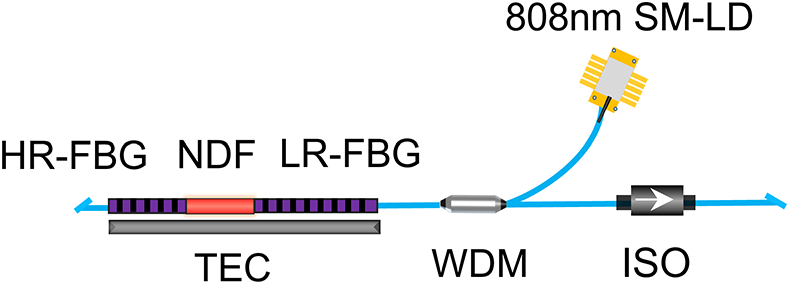
As shown in Figure 2, we firstly developed an SF seed laser based on short DBR cavity configuration to construct the high-power SFFL system and validate the performance of the homemade PM 10/125 μm NDF. The adopted gain fiber is a homemade 4/125 μm SM highly NDF. The core absorption coefficient at 808 nm of this NDF is 410 dB/m and the net gain coefficient with a –30.35 dBm input signal power at 910 nm is measured to be 1.0 dB/cm (Figure S1 in the Supplementary Material). More details about this fiber can be found in our previous study[ Reference Wang, Chen, Wang, Wang, Zhang, Feng, Yu, Dong, Wen, Chen, Yu and Hu 38 ].
Experimental setup of the DBR SF seed at 910 nm. SM-LD, single-mode laser diode; HR-FBG, high-reflectivity fiber Bragg grating; NDF, Nd-doped silica fiber; LR-FBG, low-reflectivity fiber Bragg grating; TEC, temperature controller; WDM, wavelength division multiplexer; ISO, isolator.

A 10 mm NDF is fusion spliced with a high-reflectivity fiber Bragg grating (HR-FBG) and a low-reflectivity fiber Bragg grating (LR-FBG). The reflectivity of the HR-FBG is over 99% with a 3-dB bandwidth of 0.35 nm. The reflectivity of the LR-FBG is 75%, with a 3-dB bandwidth of 0.02 nm. Before being fusion spliced with NDF, both the HR-FBG and LR-FBG were cut near their physical grating area to shorten the cavity length. The HR- and LR-FBGs were custom-made by O/E Land (Canada) and inscribed into passive Hi780 fiber with physical lengths of 1 and 4 cm, respectively. The effective grating lengths for the HR- and LR-FBGs, according to the method proposed by Barmenkov et al. [ Reference Barmenkov, Zalvidea, Torres-Peiró, Cruz and Andrés 41 ], are calculated to be 1.7 and 13.2 mm, respectively. Combined with the 10 mm length of the NDF, the effective total cavity length is 25 mm, corresponding to a free spectral range (FSR) of 4.1 GHz. Given the 0.02 nm (7.2 GHz) bandwidth of the LR-FBG, the current cavity design strictly meets the requirements for SF operation[ Reference Fu, Shi, Feng, Zhang, Yang, Xu, Zhu, Norwood and Peyghambarian 42 ]. In addition, a precise temperature controller (TEC) was used to control the cavity temperature and the laser resonator was counter-pumped by a 250 mW 808 nm single-mode laser diode (SM-LD) via an 808/910 nm wavelength division multiplexer (WDM).
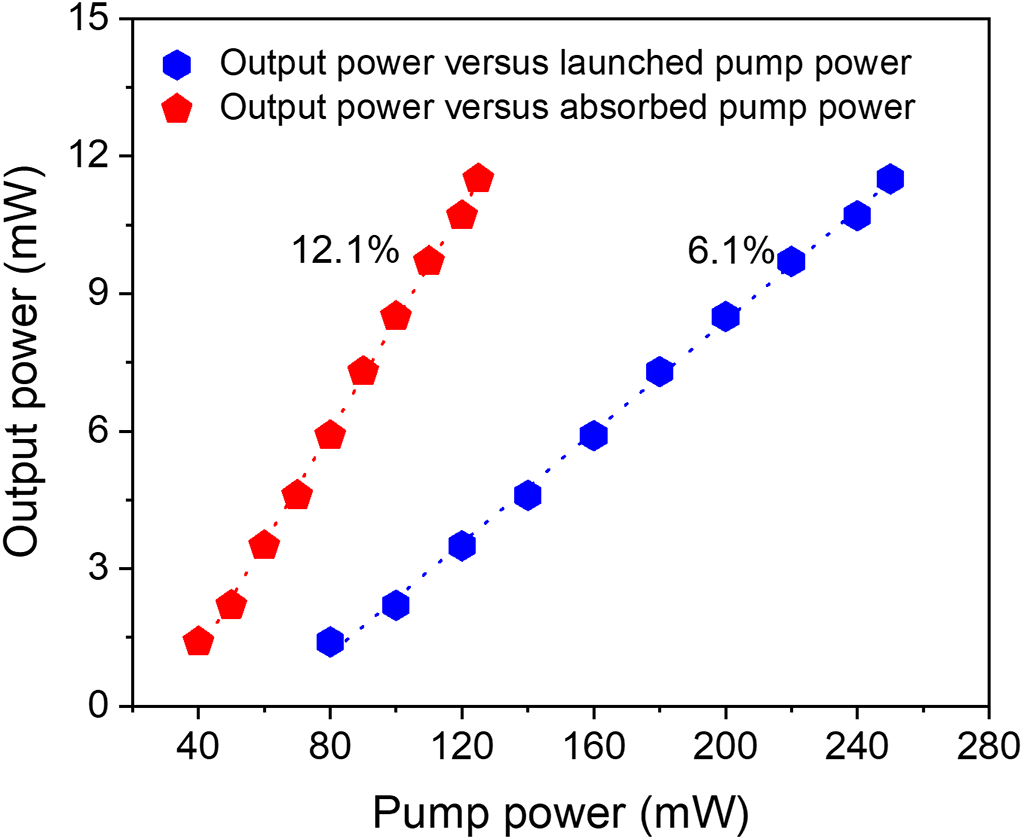
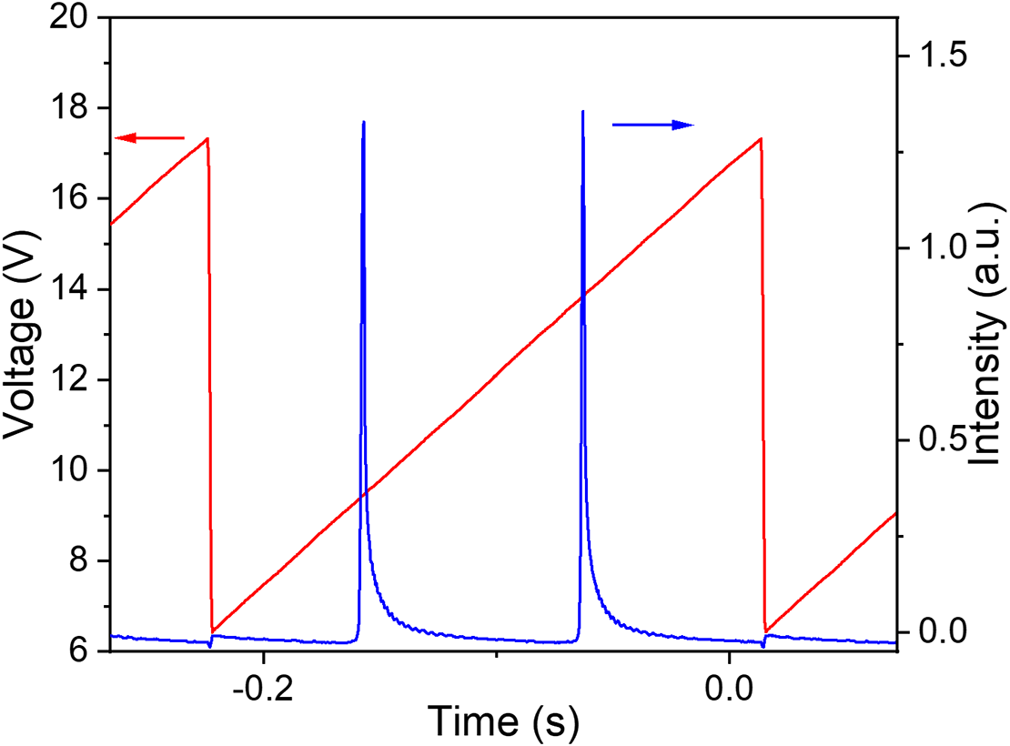
As shown in Figure 3, a maximum 11 mW seed laser was obtained after the ISO under 250 mW pump power. The slope efficiency of the laser with respect to the launched pump power is around 6.1%. When the residual pump power is excluded, the slope efficiency is 12.1%. To confirm the single longitudinal mode (SLM) operation of this seed laser, a Fabry–Pérot (F-P) interferometer with a finesse of 200, a resolution of 7.5 MHz and an FSR of 1.5 GHz was used to scan the laser signal. The result is shown in the Figure 4; there are no other peaks between the main resonances of the interferometer, which clearly indicates that only one longitudinal mode oscillates in the cavity.
Output power of the DBR seed laser.

Longitudinal mode characteristic of the DBR seed laser measured by the scanning F-P interferometer.

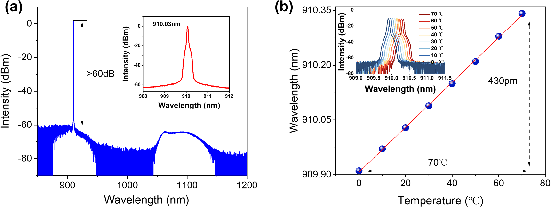
Figure 5(a) shows the measured spectra of the seed laser, in which a clear 910 nm laser signal could be observed with a signal-to-noise ratio (SNR) of over 60 dB. The inset shows the laser spectrum measured with a resolution of 0.02 nm, in which the laser center wavelength is located at 910.03 nm when the cavity was temperature controlled at 20°C. In addition, due to the strict fulfillment of the SLM condition, the seed laser exhibited excellent stability. As depicted in Figure 5(b), stable SLM operation could be sustained in the temperature range from 0°C to 70°C and the center wavelength presented continuous tunability from 909.91 to 910.34 nm with a 430 pm spectral range. The inset shows the laser spectra recorded with a 10°C interval.
(a) Laser spectra of the seed when the DBR cavity is temperature controlled at 20°C. The inset shows the laser spectrum in the region of 908–912 nm with a resolution of 0.02 nm. (b) Dependence of the laser center wavelength on the cavity temperature. The inset shows the laser spectra in the 0°C–70°C temperature range with a 10°C interval.

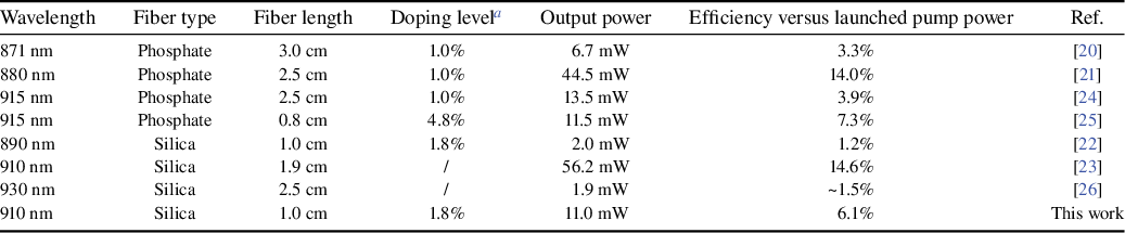
As shown in Table 1, we compared the performance of SF oscillators at approximately 900 nm based on highly Nd-doped glass fibers. The SF seeds based on NDF cover a wavelength range from 890 to 930 nm, with an efficiency ranging from 1.2% to 14.6%. In contrast, the wavelength range for phosphate glass fiber spans from 871 to 915 nm, with an efficiency between 3.3% and 14.0%. Compared to silica fiber, laser wavelengths by phosphate fibers exhibit an overall spectral shift toward being shorter, due to the blueshift of the emission peak of Nd in phosphate glass. In addition, it can be seen that the efficiency shows significant wavelength-dependent variation both in Nd-doped phosphate and silica fibers. Overall, compared to the SF oscillators in the 1.0, 1.5 and 2.0 μm bands, SF oscillators operating at approximately 900 nm present relatively low efficiency. Further laser efficiency improvement is anticipated by Nd-doped fibers with higher gain coefficients and optimized cavity conditions.
Comparison of ~900 nm Nd-doped SF oscillators realized by the DBR cavity structure.

a The doping level is in mass fraction.
2.2 Over 30 W single-mode kilohertz-linewidth SF all-fiber master oscillator power amplifier system
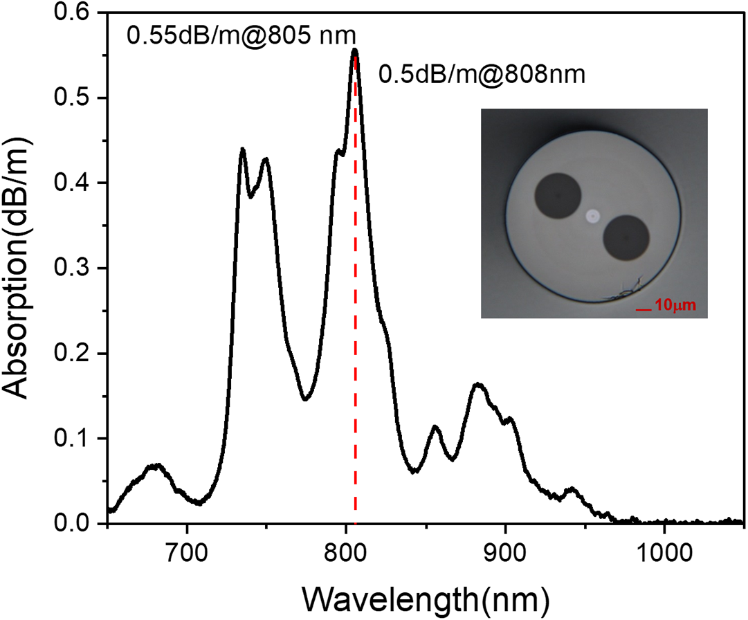
As shown in Figure 6, taking the above DBR SF oscillator as the seed source, an all-fiber master oscillator power amplifier (MOPA) system based on the homemade PM 10/125 μm NDF was further constructed. This system consists of first-stage (1st-pre) and second-stage (2nd-pre) preamplifiers and a main amplifier (main amp), which share similar configurations. The lengths of the PM 10/125 μm NDF in each stage were optimized to 2.2, 3.0 and 4.0 m, respectively. The multi-mode laser diodes (MM-LDs) at 808 nm were used as the pump and coupled into the PM 10/125 μm NDF by a PM combiner (PM-Com). A PM cladding power stripper (CPS) with maximum stripping power of 200 W was used to remove residual pump power. The pump port of the PM-Com is 105/125 μm fiber and the fiber pigtails of the signal port of all these passive components are PM 10/125 μm fiber (PLMA-GDF-10/125-M, Nufern). In addition, to prevent the excessive 1.06 μm amplified spontaneous emission (ASE) intensity accumulation and possible parasitic oscillation, PM-BPFs with a center wavelength of 906 nm and a 3 dB bandwidth of 10 nm were incorporated into the system and spliced after the PM-CPS. The transmission spectrum of this BPF is provided in Figure S2 in the Supplementary Material. The PM-ISO and Cir were also adopted to protect the system from the backward light. Figure 7 shows the cladding-pump absorption spectrum of the homemade PM 10/125 μm NDF. The absorption peak of this fiber is centered at 805 nm with a 0.55 dB/m absorption coefficient and the 808 nm is slightly offset from the absorption peak with an absorption coefficient of 0.5 dB/m. The inset in Figure 7 shows the fiber cross-section, which is a typical Panda-style PM fiber with a measured birefringence of 4.0 × 10⁻⁴. The numerical aperture of the core is 0.08.
Experimental setup of the over 30 W single-mode kilohertz-linewidth SFFL at 910 nm. PBS, polarization beam splitter; MM-LD, multi-mode laser diode; PM-Com, PM combiner; PM-NDF, PM 10/125 μm Nd-doped silica fiber; PM-CPS, PM cladding power stripper; PM-ISO, PM isolator; PM-BPF, PM bandpass filter; PM-Cir, PM circulator.

Cladding absorption spectrum of PM 10/125 μm NDF measured by the cut-back method. The inset shows the fiber cross-section.

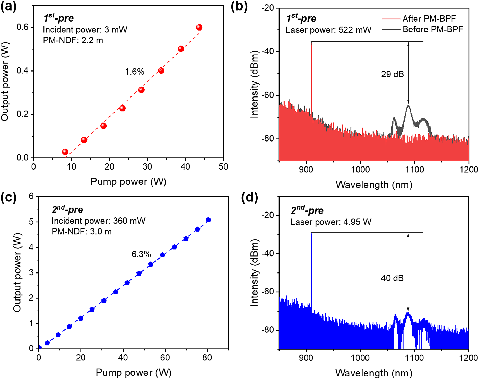
The seed laser was connected to a 910/1064 nm WDM to filter out backward-propagating 1064 nm ASE from the amplifier. A fiberized polarization beam splitter (PBS) was connected to the WDM to select a single polarization state for subsequent amplification, compatible with the design of the PM amplification stages. After passing through the WDM and PBS, the seed power was attenuated to approximately 3 mW. Figure 8(a) illustrates the output power curve of the 1st-pre; the laser power was scaled to 592 mW at a launched pump power of 44 W, corresponding to an amplification efficiency of 1.6%. The laser spectrum is shown in Figure 8(b), which presents an SNR of 29 dB at the maximum output power. Based on spectral integration, the power fraction of 1.06 μm ASE is approximately 12%. Thus, the actual laser power is calculated to be 521 mW and the gain of this amplification stage is 22.4 dB. Furthermore, it can be seen from the red curve in Figure 8(b) that the 1.06 μm ASE can be filtered out completely by the BPF. To assess whether any temporal instability exists with such high gain in the 1st-pre, we monitored the laser temporal state using a photodetector (DET10A2, Thorlabs) combined with an oscilloscope (DSOV084A, Keysight). No temporal instability was observed (Figure S3 in the Supplementary Material).
Laser performance of the preamplifiers. (a) Laser output power curve and (b) laser spectra before and after the PM-BPF of the 1st-pre. (c) Laser output power curve and (d) laser spectrum of the 2nd-pre.

After passing through the PM-BPF (insertion loss: 0.5 dB) and the PM-ISO (insertion loss: 1.0 dB), the laser power was attenuated to 360 mW. The efficiency and spectrum of the 2nd-pre are shown in Figure 8(c). A maximum 5.1 W output power was obtained at 80 W pump power. Compared with the 1st-pre, the efficiency of this stage is improved to 6.3% due to higher injected signal power and longer gain fiber length. The laser spectrum at 5.1 W output power is shown in Figure 8(d), in which the laser SNR compared to 1.06 μm ASE is 40 dB. According to spectral integration, 1.06 μm accounts for approximately 3% of the total 5.1 W output power. The actual maximum 910 nm laser power in the second amplification is 4.95 W and the gain of this amplification stage is 11.4 dB. Considering the maximum handling power of the PM-BPF and PM-Cir, the pump power of this stage was not increased to enhance the signal output power and gain, although the intensity of the 1.06 μm ASE is relatively low.
The amplified laser power of the 2nd-pre was attenuated to 4 W after passing through the PM-BPF and PM-Cir (insertion loss: 0.7 dB). Another PM-BPF was connected to the three-port PM-Cir to exclude the backward 1.06 μm ASE and guarantee the accurate measurement of SBS power. The total loss of the backward SBS monitoring chain is 1.2 dB, corresponding to a power loss of approximately 25%. The power meter used for SBS monitoring employs a Si photodiode with a minimum detectable power of 50 nW and a resolution of 1 nW (S120C, Thorlabs). Taking into account the loss of the backward monitoring chain, the actual minimum detectable SBS power is 67 nW with a resolution of 1 nW, which is sufficient for backward SBS monitoring.
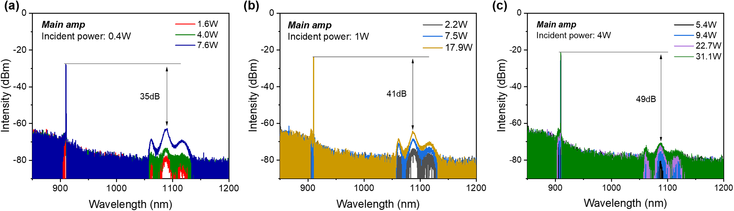
In the main amplifier, a 4 m PM 10/125 μm NDF was determined in the experiment to maximize output power while maintaining a sufficient SBS threshold. We first examined the influence of incident power on 1.06 μm emission suppression. As shown in Figure 9(a), when the incident signal power is set at 0.4 W for power scaling, the 1.06 μm ASE intensity grows rapidly with increasing laser power. As the laser power reaches 7.6 W, the laser SNR drops to 35 dB and the pump power was not increased further to prevent possible parasitic oscillation. With increasing the incident power to 1 W, the suppression of the 1.06 μm ASE is improved prominently. As the laser power reaches 17.9 W, the SNR between the 910 nm laser and 1.06 μm ASE still maintains at 41 dB (Figure 9(b)). With an incident power of 4 W, as shown in Figure 9(c), the suppression of the 1.06 μm ASE is further improved, exhibiting negligible intensity growth. Remarkably, when scaling to 31.1 W output power, the laser still maintains an SNR of 49 dB. The power fraction of the 1.06 μm ASE is less than 1% under such high spectral purity. These results demonstrate that higher incident 910 nm signal power is beneficial for suppressing 1.06 μm ASE in amplification. Furthermore, the laser spectral evolution also illustrates that if a BPF and a Cir with higher power-handling capability become available, the laser power in the 2nd-pre could be boosted further and the suppression of 1.06 μm in the main amplifier would be improved. In addition, the three-stage amplification in the current design is more rational than that of the two-stage design, as it helps prevent the growth of the 1.06 μm ASE and enables high power output.
Laser spectra at different output powers in the main amplifier with the incident power of (a) 0.4 W, (b) 1 W and (c) 4 W.

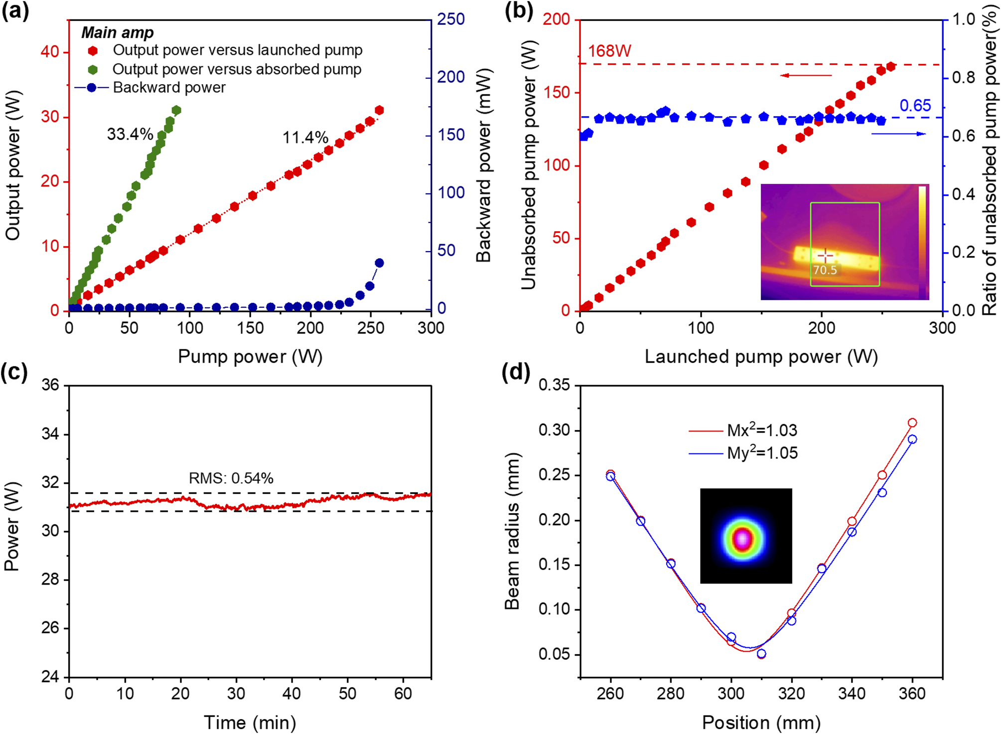
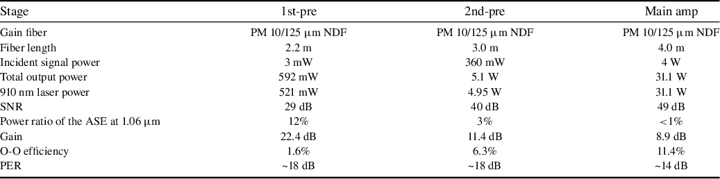
Based on the above results, the incident signal power was set to 4 W for the main amplifier. Figure 10(a) shows the output power and backward power versus pump power. A maximum output power of 31.1 W was achieved at 257 W pump power, corresponding to a slope efficiency of 11.4%. The gain of this amplification stage is 8.9 dB. Meanwhile, the backward SBS power began to nonlinearly grow when the output power was amplified beyond 27.2 W, indicating the occurrence of the SBS effect. At the maximum output power (31.1 W), the backward power was measured to be 40 mW. For better thermal dissipation and beam quality control under such high launched pump power, the PM 10/125 μm NDF was embedded in thermal grease with a coiling diameter of approximately 8–10 cm and mounted onto a water-cooled plate. A photograph of the main amplifier is provided in Figure S4 in the Supplementary Material. The water temperature was set to 21°C. In the main amplifier, approximately 65% of launched pump power remains unabsorbed (Figure 10(b)). If excluding the unabsorbed pump power, the efficiency is calculated to be 33.4%, as shown in Figure 10(a). Such laser efficiency indicates that the absorbed pump power is predominantly converted into heat rather than laser output as the theoretical quantum efficiency from 808 to 910 nm is 88.8%. Furthermore, the unabsorbed pump power causes a prominent thermal load to the CPS, as presented in the inset in Figure 10(b); its temperature reached 70.2°C, although it was coated with thermal grease and tightly fixed onto the water-cooled plate. A CPS with lower temperature rise coefficient or a directly water-cooled CPS can serve as an option for reducing temperature. We tested the power stability at the maximum output power of 31.1 W. Over a 65-min test duration, the laser power fluctuated between 30.9 and 31.6 W, with a root mean square (RMS) fluctuation of 0.54% (Figure 10(c)). As shown in Figure 10(d), the measured beam quality factors – Mx 2 and My 2 – are 1.03 and 1.05 at the maximum output power, respectively. The inset in Figure 10(d) shows the measured beam profile at maximum output power, which presents a near-Gaussian intensity profile. The performance of the amplifiers is summarized in Table 2. The polarization extinction ratio (PER) shows degradation in the main amplifier, decreasing to 14 dB compared to the 18 dB PER in the preamplifiers. We attribute the thermal effects induced by high pump power injection as the main reason for degradation of the PER. Furthermore, directly employing a linearly polarized seed is believed to help improve the system’s PER because the current scheme using a non-polarized seed combined with a PBS achieves a PER of only around 20 dB.
(a) Output power and backward power versus pump power in the main amplifier when the incident power is set at 4 W. (b) Unabsorbed pump power and its ratio compared to launched pump power. (c) Power stability of the main amplifier when operating at maximum output power. (d) Beam quality factors at maximum 31.1 W output power; the inset shows the beam profile.

Summarized parameters of the amplifiers.

The approach to reducing thermal effects lies in improving the laser efficiency. From the perspective of fiber optimization, developing NDF with a higher pump absorption coefficient and reducing the reabsorption effect of the three-level (4F3/2–4I9/2) transition are feasible directions. Co-doping certain elements, such as phosphorous (P), has been verified to be an effective way to mitigate the reabsorption effect. Increasing the Nd doping concentration also provides a direct method to enhance fiber absorption coefficient. Yet, both approaches – whether through co-doping or higher Nd concentrations – would in turn introduce new challenges in terms of refractive index control, the fluorescence quenching effect and approximately 900 nm emission characteristics. We are systematically optimizing NDF to achieve better gain control and higher absorption coefficient.
The typical progress of approximately 900 nm Nd-doped SF amplifiers was summarized and is listed in Table 3. The previous reported SF amplifiers adopted commercial W-type Nd-doped fibers as the gain medium. Such a fiber can suppress 1.06 μm emission effectively by increasing its propagation loss with suitable bending. However, the W-type index profile is only applicable to small-diameter cores (<6 μm) that suffer from a low threshold for nonlinear optical effects. As a result, W-type Nd-doped fibers are generally adopted in intermediate amplifiers in approximately 900 nm MOPA systems, including SF[ Reference Prakash, Darwich, Dixneuf, Guiraud, Traynor, Corre, Robin, Florentin, Laroche, Bertoldi, Santarelli and Hilico 36 , Reference Rota-Rodrigo, Gouhier, Laroche, Zhao, Canuel, Bertoldi, Bouyer, Traynor, Cadier, Robin and Santarelli 37 ], femtosecond[ Reference Li, Sun, Liu, Luo, Xu and Luo 43 , Reference Sun, Li, Liu, Lin, Luo, Xu and Luo 44 ] and nanosecond[ Reference Zhang, Hou, Li, Zhao and Wang 45 , Reference Cheng, Zhang, Cheng, Fang, Zhang, Yu, Li, Sun, Zhang, Zhao, Jiang, Hartl and Li 46 ] lasers. As can be seen in Table 3, the output power in these reported approximately 900 nm SF amplifiers was restricted to below 3 W. In contrast, the homemade PM 10/125 μm NDF can be employed in both intermediate and main amplifier stages, offering higher power scaling capabilities.
Performance comparison of ~900 nm Nd-doped SF amplifiers.

a Efficiency in the last amplification stage.
b Exail is formerly iXblue.
c ECDL, extended cavity diode laser.
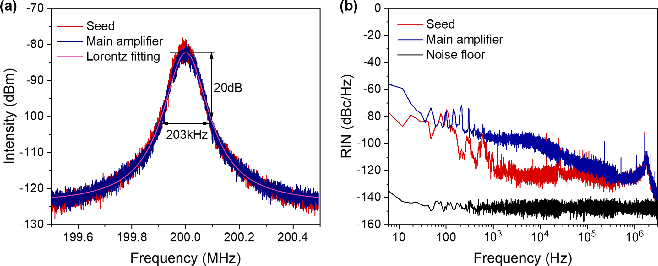
The linewidth characteristic of this laser was further explored by the self-heterodyne method. A 7-km-long SM delayed fiber and a 200 MHz acousto-optic modulator were used in the self-heterodyne system. Figure 11(a) presents the measured linewidth of the seed and amplified laser at the maximum output power. The heterodyne signals show good consistency for the seed and main amplifier with a 20 dB linewidth of 203 kHz via Lorentzian fitting, which indicates the laser linewidth is less than 10.2 kHz. The results also show that there is almost no broadening of the laser linewidth in the entire amplification process. The relative intensity noise (RIN) of the seed and main amplifier is also monitored in the frequency range of 0–3 MHz utilizing an intensity noise analyzer (PNA1, Thorlabs). The laser power was attenuated to 1.0 mW before being injected into a photoelectric detector in the measurement. The responsivity of the detector is 0.218 A/W at 910 nm (DET10A2, Thorlabs), which enables a nW-level minimum detectable power. Thus, an incident power of 1 mW is sufficient for accurate measurement. As shown in Figure 11(b), these is a dominate broad relaxation oscillation band peak at around 1.8 MHz with the RIN level of around −105 dBc/Hz. After the relaxation oscillation peak, the amplitude of the RIN monotonically decreases to less than −140 dBc/Hz at 3 MHz. The RIN of the main amplifier below 100 kHz increases compared to the seed, which is mainly caused by the power fluctuation of the laser diode pump, mechanical vibration and the fluctuation of the ambient temperature[ Reference Yuan, Sun, Xu, Zhao, Yang and Xu 47 ]. Moreover, the parasitic peaks in Figure 11(b) are attributed to the electronical pick-up noise, which can be eliminated by optimizing the driving electronics of the pump lasers.
(a) Linewidth and (b) relative intensity noise (RIN) of the seed and main amplifier.

3 Conclusion
In summary, we have developed a high-power SM Nd-doped SFFL at 910 nm with over 30 W output power while preserving exceptional 49 dB suppression of competing approximately 1060 nm emission based on a homemade NDF. The seed is a DBR SF oscillator at 910 nm constructed by a homemade 4/125 μm SM highly NDF with 11 mW output power and 430 pm wavelength tunability. The laser power was scaled to 4.95 W after two cladding-pump preamplifiers and further boosted to 31.1 W via a main amplifier using a homemade PM 10/125 μm NDF. To the best of our knowledge, this is the highest power of Nd-doped SFFLs in this spectral region reported so far. At maximum output power, the laser exhibits excellent beam quality (Mx 2 = 1.03, My 2 = 1.05) and narrow linewidth (10.2 kHz). In addition, it is also revealed that the increase of incident laser power in the main amplifier could help suppress the 1.06 μm ASE intensity. These results confirm that the homemade PM 10/125 μm NDF can be employed in both intermediate and main amplifier stages in all-fiber SF MOPA systems at approximately 900 nm toward 30 W level output power.
Supplementary material
The supplementary material for this article can be found at http://doi.org/10.1017/hpl.2026.10116.
Acknowledgements
This work was supported by the National Natural Science Foundation of China (Grant Nos. U25A20516, 62205356 and 62405351); the Natural Science Foundation of Shanghai (Grant No. 24ZR1474500); the Strategic Priority Research Program of the Chinese Academy of Sciences (Grant No. XDB0650000); and the Sichuan Provincial Natural Science Foundation (Grant No. 2024NSFSC1442).





 Open access

