

1 Introduction
The issue of laser damage to potassium dihydrogen phosphate (KDP) crystal is an important factor restricting the development of high-power laser facilities for inertial confinement fusion (ICF) such as the National Ignition Facility (NIF) in the United States, the Laser MegaJoule in France and the Shenguang Laser Facility in China[Reference Hawley-Fedder, Geraghty and Locke1–Reference Yoreo, Burnham and Whitman4]. Laser damage sites on the surface of optical components would reduce their resistance to high power lasers, accelerate the scrapping of components and deteriorate the quality of laser beams[ Reference Manes, Spaeth and Adams 5 , Reference Chen, Wang and Wang 6 ]. For high-cost optics like KDP crystal, NIF proposed a ‘recycling’ strategy to mitigate the growth of laser-induced surface damage and maximize its lifetime[ Reference Spaeth, Wegner and Suratwala 7 , Reference Demos, Kozlowski, Staggs, Chase, Bumham and Radousky 8 ]. The main method uses an optics damage inspection system to determine whether laser damage to the optics surface has occurred[ Reference Manes, Spaeth and Adams 5 , Reference Chu, Zhang and Tian 9 ]. Tiny defects such as surface fractures and laser ablation would then be replaced with specific smooth contours[ Reference Spaeth, Wegner and Suratwala 7 , Reference Hrubesh, Brusasco and Grundler 10 ]. It is a very effective and feasible method for improving laser damage resistance of optical components during subsequent laser irradiation.
As for the mitigation processes on the surface of KDP crystal, some related research has been explored in the last twenty years[ Reference Spaeth, Wegner and Suratwala 7 , Reference Gao, Ji and Wang 11 , Reference Chen, Chen, He, Ni, Liu and Li 12 ]. Hrubesh et al.[ Reference Hrubesh, Brusasco and Grundler 10 ] from the Lawrence Livermore National Laboratory (LLNL) used CW-CO2 laser processing, aqueous wet-etching, short-pulse laser ablation and micromachining to repair laser damage sites on the surface of KDP crystal. The experimental results showed that the micro-milling process proved to be the most effective method for repairing KDP crystals. Next, Geraghty et al.[ Reference Geraghty, Carr, raggoo, Hackel, Mailhiot and Norton 13 ] successfully tested all of the shaped contours of mitigation pits on KDP crystal. The laser-induced damage thresholds (LIDTs) were close to the values for the original KDP surface. Elhadj et al.[ Reference Elhadj, Steele, Vanblarcom, Hawley, Schaffers and Geraghty 14 ] investigated an improved approach for mitigating the damage sites on crystal optic surfaces with the removal of damaged anti-reflective coating. The effect of repaired mitigation shapes on laser damage resistance has been analyzed using a method based on electromagnetic field theory. Using the finite-difference time-domain (FDTD) method, Cheng et al.[ Reference Cheng, Chen, Liao, Wang, Xiao and Li 15 ] calculated the light intensification inside KDP crystal with and without mitigation pits, and verified that spherical mitigation pits with a large width–depth ratio can significantly mitigate surface damage growth by lowering the induced light intensification. Finite element method (FEM) models of mitigation pits with various structural parameters were established by Yang et al.[ Reference Yang, Cheng and Chen 16 ] to compare the light intensification caused by mitigation pits. It was found that mitigation pits with width–depth ratios greater than 5.3 and 4.3 should be applied in repaired spherical and Gaussian mitigation contours, respectively, to achieve the optimal mitigation effect.
Although the strategy and process for laser damage mitigation on KDP crystal surface have made great progress, the effect of KDP surface mitigation contours upon downstream far-field light modulation is unclear. The downstream light intensity modulation induced by the phase defects that lie on the reflection optics in one of the SG-III laser beamlines was studied by Zhang et al.[ Reference Zhang, Zhou and Dai 17 ]. They found that these surface phased defects result in strong intensity modulation after some propagation distance. Downstream light-field modulation for mitigated glass has been the subject of research, and it was found that some mitigation structure would be harmful to the downstream optics[ Reference Doualle, Gallais and Monneret 18 , Reference Jiang, Zhou and Qi 19 ]. Fused silica elements are traditionally placed after frequency converters made from KDP materials, which impose a lower relative laser damage threshold at these positions versus other components[ Reference Manes, Spaeth and Adams 5 ]. Therefore, it is of significance to clarify the influence of KDP mitigation profile on downstream light-field modulation.
In order to determine whether mitigation pits on KDP surfaces would reduce the laser damage resistance of downstream optical components, we built a model to calculate downstream light-field modulation caused by mitigation pits on the KDP rear surface based on the angular spectrum diffraction theory. The light-field modulations at different downstream locations caused by Gaussian mitigation pits were then calculated. The micro-milling method is used to replace the damage site on the KDP rear surface by a Gaussian mitigation pit with a width of 800 μm and a depth of 10 μm. The laser damage experiment for downstream optical components is designed to verify the effect of rear-surface Gaussian mitigation pits on the laser damage resistance of downstream far-field optical components. The results are not just used as evidence of the potential damage threats to downstream optics caused by Gaussian mitigation pits on a KDP rear surface, but also provide technical indexes for the installation of downstream optical elements, such as continuous phase plates and wedged focus lenses.
2 Model and theory
Gaussian geometrical contours are generally designed to mitigate the KDP crystal, which alleviates the growth behavior of laser damage sites[ Reference Cheng, Chen, Liao, Wang, Xiao and Li 15 , Reference Yang, Cheng and Chen 16 ]. They can be described by
 $$\begin{align}z\left(x,y\right)=d\cdot \exp \left[\frac{x^2+{y}^2}{{\left(w/4\right)}^2}\right].\end{align}$$
Here, the width and depth of the Gaussian contour are w = 800 μm and d = 10 μm, respectively.
There would be light-field disturbance when the laser propagates in the downstream far field due to the presence of the repair morphology on the crystal surface. Figure 1(a) is a sketch of the far-field modulation caused by the Gaussian mitigation contour on a KDP rear surface. The normally incident plane wave is distorted in phase when it passes through a rear surface with a mitigation pit. After passing through the area, the light field possesses a wavefront with a particular shape. The wavefront phase (φ) distribution of the repaired region is characterized by
 $$\begin{align}\varphi =\frac{2\pi \left(n-1\right)}{\lambda}\cdot z\left(x,y\right),\end{align}$$
where z(x,y) represents the depth of the mitigation pit on the KDP surface along the laser propagating direction, λ = 532 nm is the wavelength of incident laser and n is the refractive index in the medium of KDP crystal (1.51 at 20°C).
The effect of the Gaussian mitigation pit on the far-field propagation of the outgoing laser. (a) Sketch of the far-field modulation caused by the Gaussian mitigation contour on a KDP rear surface. (b) The relative positions of two dominant downstream light intensification patterns caused by the Gaussian mitigation pit on a KDP rear surface. D hs and D rz refer to the focal lengths of on-axis hot spot and off-axis ring caustic, respectively.

The diffraction effect of the downstream light field and the position of the light-intensity enhancement can be preliminarily analyzed by traditional geometric optics theory. Figure 1(b) shows the relative positions of two dominant downstream light intensification patterns caused by the Gaussian mitigation pit on a KDP rear surface. D hs and D rz refer to the focal lengths of on-axis hot spot and off-axis ring caustic, respectively. The off-axis ring caustic is mainly due to the arc contour around the Gaussian mitigation pit, which produces effects like a convex lens. The position of the on-axis hot spot appears relatively farther than that of the off-axis ring caustic. The hot spot is caused by the diffraction effect of uneven phase distribution of the outgoing light from the KDP rear surface.
The diffraction of the downstream light field behind the mitigation pit on a KDP rear surface can be numerically calculated using scalar diffraction theory. Since the model calculation only focuses on the light-intensity distribution at various locations downstream, the time term in Maxwell’s equations is eliminated. The Helmholtz equation without a time factor can then be obtained as[ Reference Bourgeade, Donval, Gallais, Lamaignère and Rullier 20 ]
 $$\begin{align}\left({\nabla}^2+{k}^2\right)U=0,\end{align}$$
where U = U(x,y,z) is the complex amplitude of the spatial point at (x,y,z) and k is the wave number.
Since the light-intensity distribution of the laser beam is proportional to the square of the amplitude, the product of the complex amplitude and its conjugate complex, as shown in Equation (4), can represent the intensity of the light wave
 $$\begin{align}I=U\cdot {U}^{\ast },\end{align}$$
where U * is the conjugate complex number of the complex amplitude U.
The model introduces the concept of modulation degree M to characterize the degree of disturbance of light-intensity distribution at various downstream positions, as shown in
 $$\begin{align}M=\frac{I_{\mathrm{max}}-{I}_B}{I_0-{I}_B},\end{align}$$
where I max is the maximum intensity of the diffraction pattern at a downstream position after the incident light passes through the mitigation surface, I 0 represents the light intensity after the incident light passes through the perfect KDP surface (without repaired contours) and I B is defined as the intensity value of the background pattern.
3 Experiment
In order to verify the influence of the KDP rear surface with Gaussian mitigation pits on downstream light-field modulations, three sets of experiments were carried out: fabrication of a Gaussian mitigation pit on a KDP rear surface with the micro-milling method, a test of LIDTs of a downstream fused silica surface and a KDP rear surface with a Gaussian mitigation pit, and a test of downstream laser damage at a fixed distance from the Gaussian mitigation pit on a KDP rear surface.
Gaussian mitigation pits were fabricated by micro-milling on KDP rear surfaces to provide experimental samples for subsequent laser damage experiments. A self-developed multi-axis micro-milling platform was used to mitigate the laser damage point on the rear surface of KDP crystal[ Reference Yang, Cheng and Chen 16 ]. A Gaussian mitigation pit of 800 μm width and 10 μm depth is a common set of structure parameters, which could mitigate 60.9% of laser damage sites on the KDP surface. The mitigation pit meets the criterion that the width–depth ratio of the Gaussian contour should be greater than 4.3[ Reference Yang, Cheng and Chen 16 ]. In addition, a ball-end cutter with a diameter of 500 μm is used. There is no interference between the Gaussian contour and the cutting tool during machining. The large width–depth ratio and high-quality repaired surface would contribute to improving the laser damage resistance of the KDP crystal. Thus, the rounded Gaussian profile is designed to replace the brittle fracture on the original damage site.
Subsequently, the LIDTs of KDP crystal with Gaussian mitigation pits and finished fused silica were measured. The test was performed on a laser damage test platform for small aperture optical components[ Reference Yang, Cheng and Chen 16 ]. The one-on-one test strategy for LIDT was used in the experiment. When plasma flashes in the laser irradiation area near the KDP crystal or fused silica, laser damage is considered to have taken place.
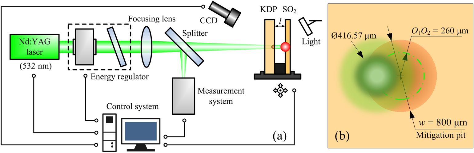
Although the modulation can be derived by actually observing the light-intensity distribution downstream, the laser damage experiment on downstream fused silica more directly proves that the mitigated KDP surface can cause laser damage to downstream optical components. According to the results of laser damage tests for a Gaussian mitigation pit on a KDP rear surface and finished fused silica, the laser damage experiment on downstream optical components was designed. The experiment is based on the laser damage test platform for small aperture optical components. A loading table is added in the experimental system to ensure that the relative distance between the KDP crystal and downstream fused silica is 10 mm. A diagram of the optical path in the experiment is shown in Figure 2(a). The laser damage test for downstream fused silica optics is performed using a pulsed laser with wavelength of 532 nm, with a duration of 8.3 ns and a frequency of 1 Hz. The laser energy passes approximately parallel through the KDP crystal and fused silica elements. The laser energy focused on the rear surface of the KDP crystal is Gaussian-shaped in space, and the effective spot diameter at the waist position is 416.57 μm (1/e2). Since the Gaussian mitigation pit could not be completely illuminated by a single laser irradiation, a laser scanning method is employed. The Gaussian laser irradiation method for a Gaussian mitigation pit on the rear surface of KDP crystal is shown in Figure 2(b). The distance O 1 O 2 between the center of the laser spot and the center of the Gaussian mitigation pit is 260 μm. A single irradiation is applied to the top, bottom, left and right positions of the Gaussian mitigation pit. The center point of the Gaussian laser spot falls on the green circle in Figure 2(b). Since the small-spot Gaussian laser adopted in the experiments would cause a change of the modulation degree and the light distribution in the diffraction pattern relative to the large flat-top laser, the influence of the Gaussian laser and the flat-top laser on the downstream light-field propagation should be compared before discussion of the experimental results. During the experiment, it is necessary to guarantee the positional accuracy of the loading table and the output energy stability of the laser path. After laser irradiation, the laser damage site on fused silica was observed and analyzed by optical microscope.
Laser damage test of a downstream fused silica component induced by a Gaussian mitigation pit on the KDP rear surface. (a) Optical path diagram of the laser damage experiment for downstream fused silica components. (b) Schematic of laser irradiation to a Gaussian mitigation pit on the rear surface of a KDP crystal.
4 Results and discussion
4.1 Downstream light-field perturbation caused by Gaussian mitigation contour
Gaussian mitigation pits on the rear surface of KDP crystal would cause disturbance of incident laser propagation and obvious downstream diffraction phenomena accompanied by severe light-intensity enhancement at various distances from a KDP rear surface. Figure 3 shows the diffraction patterns at different downstream positions from the Gaussian mitigation pit on a KDP rear surface. A Gaussian mitigation pit with the fixed structural parameters of width 800 μm and depth 10 μm is adopted for calculation. With a diffraction distance of 10 mm, the entire light almost converges on a bright string with a diameter of ~770 μm. Although there are several diffraction fringes, their relative light intensity is much lower than that of the brightest string. According to the theoretical analysis of the light-intensity enhancement in Section 2, it can be inferred that the brightest string is the off-axis ring caustic as shown in Figure 1(b). Due to the strong light intensification at the location of light convergence, there will be a significant threat to the normal use of downstream optical components. When the downstream position is 20 mm from the rear surface, the diffraction rings start to expand outward, and generate some second-brightest rings near the brightest one. This indicates that the focusing intensity has started to weaken, and the laser energy is gradually dispersed to the area around the focus. At a distance of 30 mm, a hot spot appears at the center of the diffraction pattern. Nevertheless, compared with the surrounding bright rings, the light intensification of the hot spot is much weaker. At this time, the off-axis ring caustic is still dominant in the light-field modulations. But the occurrence of the hot spot of the central light intensification verifies the diffraction effect caused by the uneven phase distribution in the theoretical analysis in Section 2. At a distance of 50 mm, not only the number of off-axis bright rings increases, but their relative light intensity also decreases significantly. The central hot spot area also becomes larger. When the distance from the rear surface is 90 mm, the light-intensity distribution of the diffraction pattern is similar to the case with 70 mm distance position. But the bright rings in the diffraction pattern at the Z = 90 mm position are larger than that of Z = 70 mm. According to the overall evolution of diffraction patterns, the off-axis ring caustic appears first, and then gradually disperses into multiple bright rings as the distance from the rear surface increases. Meanwhile, the light intensification decreases slowly. The location of the on-axis hot spot appears behind the off-axis ring caustic (more than 30 mm away from the KDP rear surface). The hot spot area continues to grow as the distance increases, and the light-intensity enhancement may dominate at certain locations. The simulated patterns are similar to the results for interferograms caused by a mitigation site at 20 mm downstream distance, which was measured by Geraghty et al. [ Reference Geraghty, Carr, raggoo, Hackel, Mailhiot and Norton 13 ]. It also shows that the diffraction phenomenon caused by laser propagation and phase contrast is universal and consistent.
The far-field diffraction patterns caused by the Gaussian mitigation contour with a width of 800 μm and a depth of 10 μm at downstream distance of (a) Z = 10 mm; (b) Z = 20 mm; (c) Z = 30 mm; (d) Z = 50 mm; (e) Z = 70 mm; (f) Z = 90 mm.
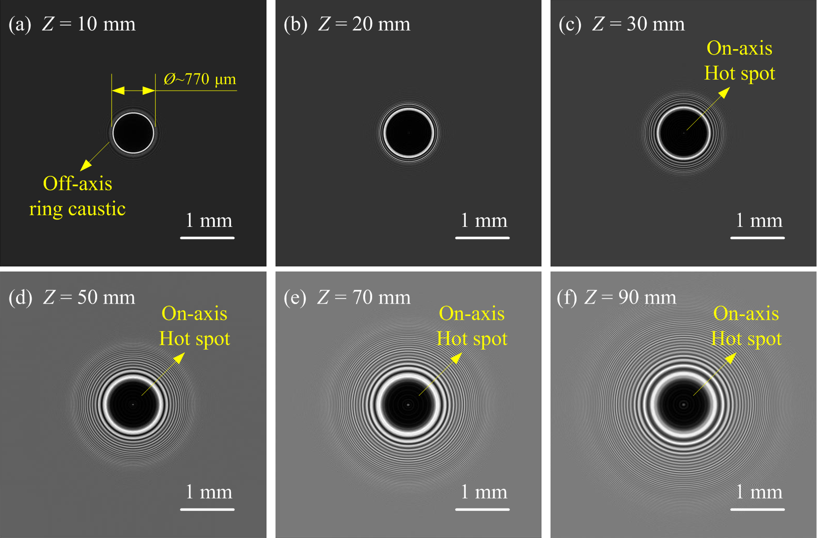
Figure 4 shows the downstream light-field modulations caused by the Gaussian mitigation pits on KDP crystal and fused silica. The red line in Figure 4 represents the evolution of light-field modulations calculated by the KDP crystal model in Section 2. The blue line corresponds to downstream light-field modulations of fused silica, which are reported by Bai et al. [ Reference Bai, Zhang and Liao 21 ]. There is a big difference between these two cases. The downstream light-intensity enhancement caused by the mitigation pit on the KDP crystal increases sharply, then decreases rapidly, and eventually keeps stable with the increase of light-propagation distance. At a position of ~10 mm from the KDP rear surface, the light-intensity enhancement reaches a maximum, which is mainly related to the energy accumulation produced by the off-axis ring caustic. Despite the generation of the on-axis hot spot in the diffraction pattern as shown in Figures 3(c)–3(f), the light-intensity enhancement does not maintain a high level as the off-axis ring caustic fades. The Gaussian mitigation pits on fused silica, however, produce a secondary intensity enhancement peak at a distance from the rear surface of the fused silica component. Due to the repair principle of CO2 laser irradiation and the material removal mechanisms of melting and evaporation for fused silica components, a raised rim is formed around the repaired profile, resulting in an increase in far-field focused spot energy.
Comparison of the downstream light-field modulations between the Gaussian mitigation pits on KDP crystal and fused silica.

4.2 Gaussian mitigation pit manufacture
KDP crystals inevitably undergo laser-induced damage (LID) under high power laser irradiation. Figure 5(a) is a scanning electron microscope (SEM) image of the laser damage site on a crystal surface after laser irradiation at a wavelength of 355 nm, duration 3 ns and fluence 8 J/cm2. The size of the laser damage site would sharply become larger under subsequent laser irradiation.
Microscopic morphology of laser damage and Gaussian mitigation profile. (a) SEM image of a laser damage site on the surface of a KDP crystal. (b) Optical micrograph of a KDP surface with a Gaussian mitigation pit. The inset is the three-dimensional shape of the Gaussian mitigation pit with a width of 800 μm and a depth of 10 μm. (c) Two-dimensional profile of the Gaussian mitigation pit and the damage site. The first inset is the local enhanced image. The second inset shows the edge profile of the mitigated KDP contour and the mitigated fused silica contour.
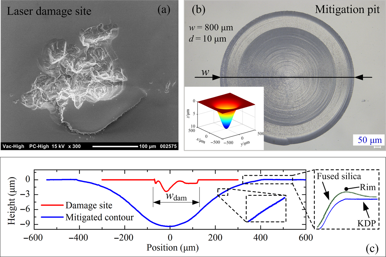
Figure 5(b) shows an optical micrograph of the KDP surface with a Gaussian mitigation pit after the micro-milling processes. The inset is the three-dimensional shape of the Gaussian mitigation pit with a width of 800 μm and a depth of 10 μm. The material near the surface defects of the KDP crystal is removed and substituted with the designed mitigation contours. The repaired crystal surface is regular, smooth and neat, with a surface roughness better than 30 nm. The relative transmittance of the repaired crystal surface is greater than 95% compared with that of a diamond fly-cut KDP surface. Figure 5(c) is the two-dimensional profile of the Gaussian mitigation pit and the damage site. The damage site on the crystal surface is completely enveloped by the repaired contour. The inset of the local enhanced image shows that even at the waist where the slope changes the most, the repair surface remains smooth. Due to the different processing methods for surface repair on KDP crystal and fused silica, the surrounding raised rim would be produced on the edge contour of the mitigated fused silica surface, which can be seen in the second inset. This rim is formed from the mass movement of silica at high temperatures from the low viscosity central region outwards during CW-CO2 laser processing, and can be several microns high. The micro-mechanical method is utilized to repair the KDP surface, however. The repair process is more controllable and there is no rim similar to the fused silica on the edge of the mitigated KDP contour. Thus, the Gaussian mitigation pit in the model can fully describe the repaired contour.
4.3 Laser-induced damage thresholds
The LIDTs are tested to provide a reliable data reference for laser damage experiments for downstream optical components caused by mitigation pits on an upstream KDP rear surface. Figure 6 shows the LIDTs for a Gaussian mitigation pit on a KDP rear surface and a front surface of fused silica. Their LIDTs were 15.44 J/cm2 and 46.47 J/cm2, respectively, with a coefficient of determination of 0.974 and 0.977, respectively. The R 2 of the fitting curve on LIDT is close to 1, indicating that the test results for LIDTs are credible. The key of the experiment is to observe changes in the downstream fused silica components while ensuring that no damage occurred in the laser-irradiated area of the KDP crystal. Therefore, the applied fluence of a single laser irradiation is 10 J/cm2, which is absolutely safe for repaired KDP crystals.
LIDTs for the Gaussian mitigation pit on (a) the KDP rear surface and (b) the front surface of fused silica.

4.4 Laser damage performance of downstream fused silica components
In Section 3 the mitigation pit is irradiated by a small-spot pulse laser with a spatial energy distribution of Gaussian profile. Therefore the influence of the Gaussian laser and the flat-top laser on the downstream light-field propagation is compared first. Figure 7(a) shows a simulation schematic of light propagation when the KDP rear surface with mitigation pit is irradiated by a Gaussian laser. The distance between the center positions of the Gaussian laser spot and the Gaussian mitigation pit is assumed to be O 1 O 2. The laser with spatial energy distribution of Gaussian shape and wavelength of 532 nm transmits from the rear surface of the crystal. The effective diameter of the laser spot for the calculation is consistent with the experimentally applied laser spot size (416.57 μm), which is close to the waist diameter of the repaired Gaussian contour. In order to find the effect of the spatial position of the laser spot on light diffraction, the light-field modulations corresponding to various distances O 1 O 2 are calculated. Figure 7(b) is a comparison of the light-field modulation generated by the flat-top laser and the Gaussian laser at the position 10 mm downstream from the Gaussian mitigation pit on the KDP rear surface, where the blue and red lines indicate the variations of light-field modulation with respect to the distance O 1 O 2, respectively. The blue line is parallel to the coordinate axis of O 1 O 2, and the corresponding value on the ordinate axis of light-field modulation is almost constant at 6.85, which indicates that the light-field modulation at the position 10 mm from the rear surface of the crystal does not change when the position of the flat-top laser moves away from the center of the Gaussian mitigation contour. For crystals irradiated by a Gaussian laser, however, the downstream light-field modulation tends to first increase and then decrease with the increase of O 1 O 2. The red line is obtained by fitting a series of calculated results, and the overall appearance is a two-dimensional Gaussian shape. At the position O 1 O 2 = 260 mm, the curve reaches the highest point, and the corresponding modulation degree M is 5.63, which is slightly smaller than that under the condition of flat-top laser irradiation. When the center point distance O 1 O 2 is 260 mm, the light-field diffraction pattern at the position 10 mm downstream is shown in the inset in Figure 7(b). The bright region in the diffraction pattern is generally annular in shape, similar to the off-axis ring caustic predicted theoretically in Figure 1(b). The light-intensity energy distribution of the diffracted bright region is, however, uneven. The maximum value of the light-intensity intensification is located at the center position of the corresponding Gaussian laser, and the energy at both sides is gradually attenuated. Combined with the above calculations of beam patterns provided by the small-spot Gaussian laser, the experimental results can be analyzed and discussed.
Comparison of the downstream light-field modulations caused by a Gaussian mitigation pit on the KDP rear surface with irradiation by flat-top laser and Gaussian laser. (a) Simulation schematic of light propagation when the KDP rear surface with mitigation pit is irradiated by incident laser. (b) Comparison of the light-field modulation generated by the flat-top laser and the Gaussian laser at a position 10 mm downstream. The inset is a diffraction pattern produced by a Gaussian laser at a position 10 mm downstream away from the crystal surface with a mitigation pit when the center point distance O 1 O 2 is 260 mm.

When the Gaussian mitigation pit on the rear surface of the crystal is exposed to laser irradiation, a plasma flash in the local area can be observed by the CCD. After the laser damage experiment, the surface of the downstream fused silica optics was examined using microscopy. The SEM micrographs of the laser damage sites on a fused silica surface are shown in Figure 8. The laser damage morphology can be divided into ‘pansy’ (in Figure 8(a)) and ‘mussel’ (in Figure 8(b)) forms, which are similar to the typical damage morphology reported by Carr et al. [ Reference Carr, Matthews, Bude and Spaeth 22 , Reference Carr, Cross, Norton and Negres 23 ] and Wong et al. [ Reference Wong, Ferriera, Lindsey, Haupt, Hutcheon and Kinney 24 ]. There would be some melting traces in the center and fracture region around the pansy damage site. The inset in Figure 8(a) shows the microscopic morphology of solidification material after melting. The mussel damage sites are mainly caused by fracture. The inset in Figure 8(b) shows the fracture surface of the KDP surface. The evidence of the damage sites proved that the Gaussian mitigation pit on the crystal surface under low-fluence laser irradiation could still cause laser damage on downstream fused silica components.
Microscopic morphology of the laser damage sites on downstream fused silica surface observed by SEM. (a) Pansy damage site; (b) mussel damage sites.

Figures 9(a) and 9(b) are a comparison between the simulations and experiments for laser damage of downstream optical components, respectively. The simulation results show that due to the influence of the mitigation pit on the KDP rear surface on the phase of the transmitted light wave, a local dark field appears at the center of the downstream light field behind the repaired area. There is, however, a significant enhancement in light intensity on both sides of the central axis due to the laser diffraction effect, and the light-field modulation is more than 6 at the position 10 mm downstream. The one-dimensional distribution of light-field modulation at this position along the x direction is shown by the red line in Figure 9(b), and the peaks on both sides correspond to the position of the off-axis ring caustic as shown in Figure 3(a), with an equivalent diameter of ~770 μm. The blue line in Figure 9(b) is the theoretical probability distribution of laser damage on downstream fused silica at a distance of 10 mm from the KDP rear surface when the center of the Gaussian laser irradiates along the green ring in Figure 2(b). The probability of laser damage is ~20% in the ring region with a diameter of 770 μm and a center point located at the center of the Gaussian mitigation contour. Observing the microscopic morphology of laser damage sites on fused silica, it is found that although the laser damage locations are unevenly distributed, they are all on the same circumference. There are a large number of laser damage sites on the left side of the micrograph, and only a small number of sporadic damage sites are distributed on the right side. The center of the laser spot is on the ring with a diameter of 540 μm, but the damage position is on the ring with a diameter of 790 μm, which is not located at the maximum energy region of the Gaussian laser. The error is less than 3% compared to the simulation result of 770 μm. The laser damage area on the ring is about 20%–25% of the total area of the ring, which is close to the simulation results for laser damage probability. The comparisons above between the simulations and the experiments prove the validity of the model. This also verifies from the opposite side that the theory and method of the laser damage experiment for downstream optical components are reasonable and correct. In general, simulation and experimental methods can strongly prove the modulation effect of the mitigation pit on the downstream light field, which needs to be considered in advance during the surface repair of crystals as well as the installation process.
Comparison between the calculations and experiments. (a) Two-dimensional distribution of downstream light-field modulation along the laser propagation (z-axis) caused by the Gaussian mitigation pit on the rear surface of a KDP crystal. (b) Optical micrograph of laser damage morphology on downstream fused silica components.

5 Conclusions
The effects of Gaussian mitigation pits on the rear surfaces of KDP crystals upon the laser damage property of downstream fused silica optics were theoretically and experimentally investigated. By calculating the downstream light-intensity distribution from the KDP rear surface with mitigation pits of various widths and depths, it is found that severe light intensification is produced in the downstream light field due to the phase contrast and its induced diffraction effect. The downstream light-field modulations induced by Gaussian mitigation pits would change with various downstream locations, and two modulation curve peaks are generated due to the off-axis ring caustic and the on-axis hot spot. The main peak near the rear surface of the crystal is modulated more heavily, posing a bigger threat to downstream fused silica optics. Different from the mitigation effect of the fused silica, there is a lesser secondary peak caused by the Gaussian mitigation pits on the KDP crystal. The experimental results for laser damage upon downstream fused silica show that the Gaussian mitigation pit on the rear surface of the crystal would cause LID on downstream fused silica at a position 10 mm away from the KDP rear surface. The location and probability of the laser damage sites are consistent with the simulations, which proves that the theoretical results of downstream light-field modulation calculated by angular spectrum diffraction theory are valid and effective. This work could provide theoretical and experimental guidance for the subsequent repair processes and installation of KDP crystal components.
Acknowledgements
This work was supported by the Science Challenge Project (No. TZ2016006-0503-01), National Natural Science Foundation of China (Nos. 51775147 and 51705105), Young Elite Scientists Sponsorship Program by CAST (No. 2018QNRC001), China Postdoctoral Science Foundation (Nos. 2017M621260 and 2018T110288), Heilongjiang Postdoctoral Fund (No. LBH-Z17090) and Self-Planned Task Foundation of State Key Laboratory of Robotics and System (HIT) of China (Nos. SKLRS201718A and SKLRS201803B).


 Open access