


1. Introduction
The melting process is of critical importance in various geophysical and industrial fields, including the melting of icebergs and ice shelves (Huppert & Turner Reference Huppert and Turner1978; Epstein & Cheung Reference Epstein and Cheung1983; Dutrieux et al. Reference Dutrieux, Stewart, Jenkins, Nicholls, Corr, Rignot and Steffen2014; Ristroph Reference Ristroph2018), the food industry (Rahman Reference Rahman2020) and the melting of phase-change materials (Dhaidan & Khodadadi Reference Dhaidan and Khodadadi2015). Given the rapid depletion of the Earth’s ice reserves (Chen et al. Reference Chen, Wilson and Tapley2006; Sutherland et al. Reference Sutherland, Jackson, Kienholz, Amundson, Dryer, Duncan, Eidam, Motyka and Nash2019), understanding the melting behaviour of ice is increasingly crucial in our warming climate. The accelerated loss of icebergs and sea ice floes significantly impacts climate and environmental changes, such as the reduction of the Atlantic meridional overturning circulation (Srokosz et al. Reference Srokosz, Baringer, Bryden, Cunningham, Delworth, Lozier, Marotzke and Sutton2012), the reduction of sea ice cover and thus a loss of albedo (Pistone et al. Reference Pistone, Eisenman and Ramanathan2014; Jenkins & Dai Reference Jenkins and Dai2021), and the enhanced drawdown and sequestration of $\text{CO}_{2}$
(Smith et al. Reference Smith, Sherman, Shaw and Sprintall2013; Duprat et al. Reference Duprat, Bigg and Wilton2016). Consequently, it is essential to improve current climate models to more accurately predict observed changes in ice cover. Enhancing our understanding of ice sheet–ocean interactions on a fundamental level is imperative, as the physical processes governing these interactions remain inadequately understood (Truffer & Motyka Reference Truffer and Motyka2016; Malyarenko et al. Reference Malyarenko, Wells, Langhorne, Robinson, Williams and Nicholls2020; Cenedese & Straneo Reference Cenedese and Straneo2023; Du et al. Reference Du, Calzavarini and Sun2024).
$\text{CO}_{2}$
(Smith et al. Reference Smith, Sherman, Shaw and Sprintall2013; Duprat et al. Reference Duprat, Bigg and Wilton2016). Consequently, it is essential to improve current climate models to more accurately predict observed changes in ice cover. Enhancing our understanding of ice sheet–ocean interactions on a fundamental level is imperative, as the physical processes governing these interactions remain inadequately understood (Truffer & Motyka Reference Truffer and Motyka2016; Malyarenko et al. Reference Malyarenko, Wells, Langhorne, Robinson, Williams and Nicholls2020; Cenedese & Straneo Reference Cenedese and Straneo2023; Du et al. Reference Du, Calzavarini and Sun2024).
The coupling between fluid motions and the evolution of solid boundaries driven by the melting process results in a moving free-boundary problem, i.e. the Stefan problem (Rubinstein Reference Rubinstein1971). This problem is highly complex since the evolution of the surface forms part of the solution to be determined. During melting, the solid–liquid interface continually recedes due to the heat flux across it, and the meltwater released by the phase change process subsequently alters the temperature field in the surrounding fluid. Temperature changes lead to density variations that drive buoyancy-driven convective flows. While buoyancy-driven convective flows with fixed boundaries are well studied (Bejan Reference Bejan1993; Kadanoff Reference Kadanoff2001; Ahlers et al. Reference Ahlers, Grossmann and Lohse2009; Lohse & Xia Reference Lohse and Xia2010; Schlichting & Gersten Reference Schlichting and Gersten2017; Lohse & Shishkina Reference Lohse and Shishkina2023, Reference Lohse and Shishkina2024), the underlying mechanisms governing the interplay between morphology evolution driven by melting, and the dynamics of buoyancy-driven convective flow remain to be developed and explored.
Many previous experimental and numerical studies have investigated the interaction between ice melting and ambient flow at laboratory scales, including dispersed ice melting in flows (Vanier & Tien Reference Vanier and Tien1970; Hao & Tao Reference Hao and Tao2002; Hester et al. Reference Hester, McConnochie, Cenedese, Couston and Vasil2021; Weady et al. Reference Weady, Tong, Zidovska and Ristroph2022; Yang et al. Reference Yang, Howland, Liu, Verzicco and Lohse2024b
), the influence of convective flows (Davis et al. Reference Davis, Müller and Dietsche1984; Dietsche & Müller Reference Dietsche and Müller1985; Favier et al. Reference Favier, Purseed and Duchemin2019; Wang et al. Reference Wang, Calzavarini, Sun and Toschi2021a
,
Reference Wang, Jiang, Du, Sun and Calzavarinib
; Yang et al. Reference Yang, Howland, Liu, Verzicco and Lohse2023), the impact of shear (Couston et al. Reference Couston, Hester, Favier, Taylor, Holland and Jenkins2021; Hester et al. Reference Hester, McConnochie, Cenedese, Couston and Vasil2021), and the effect of rotation (Ravichandran & Wettlaufer Reference Ravichandran and Wettlaufer2021; Toppaladoddi Reference Toppaladoddi2021; Ravichandran et al. Reference Ravichandran, Toppaladoddi and Wettlaufer2022). Additionally, the melting process in water is notably complex due to the unique effect of temperature on the density of liquid water, which reaches a maximum at approximately $4^{\,\circ }\mathrm{C}$
. This density anomaly leads to distinct regimes of ice morphology and melting rates under varying ambient water temperatures (Wang et al. Reference Wang, Jiang, Du, Sun and Calzavarini2021a
; Weady et al. Reference Weady, Tong, Zidovska and Ristroph2022).
$4^{\,\circ }\mathrm{C}$
. This density anomaly leads to distinct regimes of ice morphology and melting rates under varying ambient water temperatures (Wang et al. Reference Wang, Jiang, Du, Sun and Calzavarini2021a
; Weady et al. Reference Weady, Tong, Zidovska and Ristroph2022).
Despite extensive investigations into the fundamental mechanisms of the melting process (Dhaidan & Khodadadi Reference Dhaidan and Khodadadi2015; Malyarenko et al. Reference Malyarenko, Wells, Langhorne, Robinson, Williams and Nicholls2020; Cenedese & Straneo Reference Cenedese and Straneo2023; Du et al. Reference Du, Calzavarini and Sun2024), the effect of geometry on the melt rate has received comparatively less attention. Icebergs and ice floes exhibit significant variations in shape and size, with horizontal extents ranging from several metres to several hundred kilometres (Budd et al. Reference Budd, Jacka and Morgan1980; Silva et al. Reference Silva, Bigg and Nicholls2006; Andres et al. Reference Andres, Silvano, Straneo and Watts2015; Rackow et al. Reference Rackow, Wesche, Timmermann, Hellmer, Juricke and Jung2017). A limited number of experiments and simulations have shown that the overall melt rate depends on the aspect ratio (Hester et al. Reference Hester, McConnochie, Cenedese, Couston and Vasil2021; Yang et al. Reference Yang, van den Ham, Verzicco, Lohse and Huisman2024a , Reference Yang, Howland, Liu, Verzicco and Lohseb ). Hester et al. (Reference Hester, McConnochie, Cenedese, Couston and Vasil2021) conducted a comprehensive set of laboratory experiments and numerical simulations to examine the relationship between melt rate and iceberg size and shape under three distinct ambient velocities. The depth of the ice block was fixed, and its length was varied to explore how the aspect ratio influences the melt rate. They revealed that the geometry significantly affects iceberg melt rates. In their study, the volume of the ice block is altered as the aspect ratio changes. This raises another fundamental question: for the ice blocks with fixed volume, how do the melt rates depend on the aspect ratio? It is essential to maintain a constant initial volume (or area) for the investigation of shape effects. If the initial volumes (or areas) were to vary, then the melt time required to reach a given fraction of the initial volume (or area), as well as the corresponding mean melt rate, would depend on both the initial volume (or area) and the aspect ratio. This interdependence would obscure the isolated influence of aspect ratio on the melting dynamics. To address this, Yang et al. (Reference Yang, Howland, Liu, Verzicco and Lohse2024b ) investigated the influence of the initial aspect ratio on the melting dynamics of an elliptical ice block immersed in a uniform external flow. They found that the shape of the ice block strongly affects the melt rate, and the aspect ratio corresponding to the slowest melt rate varies with the strength of the external flow. Furthermore, Yang et al. (Reference Yang, van den Ham, Verzicco, Lohse and Huisman2024a ) studied the effect of the initial aspect ratio on the melting dynamics of an elliptical shape of ice immersed in quiescent fresh water, where natural convection driven by thermal buoyancy governs the flow. They observed a non-monotonic relationship between the melt rate and the initial aspect ratio, with circular shapes not exhibiting the slowest melt rate in quiescent fresh water. They also proposed a theoretical model to predict the mean melt rate. However, their model differs from the results of direct numerical simulations and fails to capture the non-monotonic dependence of the melt rate on the initial aspect ratio. This highlights the need for an improved theoretical model capable of accurately predicting the non-monotonic relationship between the initial aspect ratio and melt rate. Moreover, the neglect of the aspect ratio effect in current climate models emphasises the necessity of including this factor to more accurately predict iceberg melt rates.
For rectangular ice blocks with a fixed volume (or area), an increase in the initial aspect ratio reduces the surface area of the side walls while increasing the surface area of the basal walls. As a result, the side melt rate is expected to decrease, whereas the basal melt rate should increase with increasing initial aspect ratio. Thus the non-monotonic dependence of the overall melt rate on the initial aspect ratio can be attributed to the competition between side and basal melting. To quantify this non-monotonic behaviour, it is logical to first investigate the theoretical scaling relations for the side and basal melt rates as a function of the initial aspect ratio separately. These scaling relations can subsequently be integrated to develop a theoretical model for predicting the overall melt rate. Such an approach is extendable to geophysical icebergs. If the scaling relations for the side and basal melt rates of geophysical icebergs can be determined or extrapolated, then it becomes possible to estimate their overall melt rate through these scaling relations.
In this study, we numerically and theoretically investigate the influence of the initial aspect ratio on both side and basal melting of a rectangular ice block with fixed volume (or area) in quiescent fresh water through direct numerical simulations. We propose theoretical scaling relations to characterise the effect of the initial aspect ratio on the side and basal melt rates. Additionally, we introduce a comprehensive theoretical model that correlates the overall melt rate with the initial aspect ratio, derived from the individual scaling relations for side and basal melt rates. Our numerical results demonstrate that the proposed theoretical scaling relations and model can accurately predict the effect of the initial aspect ratio on the side, basal and overall melt rates across varying Rayleigh numbers and ambient temperatures.
The paper is organised as follows. In § 2, we detail the governing equations, control parameters and numerical methods employed in the simulations. Section 3 presents the effect of aspect ratio on side, basal and overall melt rates across varying Rayleigh numbers with a constant ambient temperature. In § 4, we examine the impact of aspect ratio on side, basal and overall melt rates for different ambient temperatures, while maintaining a fixed Rayleigh number. Finally, we provide conclusions and an outlook in § 5.
2. Numerical method and set-up
In the present study, we rely on the phase field method (Hester et al. 2020) to simulate the melting process of a solid in fresh water. This method has been validated extensively and employed in numerous previous investigations (Favier et al. Reference Favier, Purseed and Duchemin2019; Couston et al. Reference Couston, Hester, Favier, Taylor, Holland and Jenkins2021; Hester et al. Reference Hester, McConnochie, Cenedese, Couston and Vasil2021; Liu et al. Reference Liu, Ng, Chong, Lohse and Verzicco2021; Yang et al. Reference Yang, Howland, Liu, Verzicco and Lohse2023, Reference Yang, van den Ham, Verzicco, Lohse and Huisman2024a
,
Reference Yang, Howland, Liu, Verzicco and Lohseb
). The phase field variable $\phi$
is integrated in both time and space, transitioning smoothly from value 1 in the solid phase to 0 in the liquid phase, with the interface defined at
$\phi$
is integrated in both time and space, transitioning smoothly from value 1 in the solid phase to 0 in the liquid phase, with the interface defined at $\phi =1/2$
. The governing equations, under the incompressibility condition
$\phi =1/2$
. The governing equations, under the incompressibility condition $\boldsymbol{\nabla }\boldsymbol{\cdot} \boldsymbol{u}=0$
, are
$\boldsymbol{\nabla }\boldsymbol{\cdot} \boldsymbol{u}=0$
, are
 \begin{equation} \frac {\partial \boldsymbol{u}}{\partial t}+\boldsymbol{u}\boldsymbol{\cdot} \boldsymbol{\nabla }\boldsymbol{u}=-\frac {\boldsymbol{\nabla }p}{\rho _{0}}+\nu \,{\nabla }^{2}\boldsymbol{u}-\frac {g{\rho }'}{\rho _{0}} \boldsymbol{e}_{y}-\frac {\phi \boldsymbol{u}}{\eta }, \end{equation}
 \begin{equation} \frac {\partial T}{\partial t}+\boldsymbol{u}\boldsymbol{\cdot} \boldsymbol{\nabla }T=\kappa\, {\nabla }^{2}T+\frac {\mathcal{L}}{c_{p}}\frac {\partial \phi }{\partial t}, \end{equation}
 \begin{align} \frac {\partial \phi }{\partial t}=C\,{\nabla }^{2}\phi -\frac {C}{\varepsilon ^{2}}\phi \left ( 1-\phi \right )\left ( 1-2\phi +\frac {\varepsilon }{\Gamma }\left ( T-T_{m} \right )\right ). \\[6pt] \nonumber \end{align}
Here, $\boldsymbol{u}$
denotes the velocity field,
$\boldsymbol{u}$
denotes the velocity field, ${\rho }'=\rho -\rho _{0}$
is the fluctuating density from a reference value
${\rho }'=\rho -\rho _{0}$
is the fluctuating density from a reference value $\rho _{0}$
,
$\rho _{0}$
, $p$
is the kinematic pressure,
$p$
is the kinematic pressure, $T$
is the temperature,
$T$
is the temperature, $T_{m}=0^{\,\circ }\textrm {C}$
is the equilibrium melting temperature,
$T_{m}=0^{\,\circ }\textrm {C}$
is the equilibrium melting temperature, $\nu$
is the kinematic viscosity,
$\nu$
is the kinematic viscosity, $g$
represents gravitational acceleration in the vertical direction
$g$
represents gravitational acceleration in the vertical direction $\boldsymbol{e}_{y}$
,
$\boldsymbol{e}_{y}$
, $\kappa$
is the thermal diffusivity,
$\kappa$
is the thermal diffusivity, $\mathcal{L}$
is the latent heat, and
$\mathcal{L}$
is the latent heat, and $c_{p}$
is the specific heat capacity. The density anomaly of water near
$c_{p}$
is the specific heat capacity. The density anomaly of water near $4^{\,\circ }\textrm {C}$
is incorporated using the relation
$4^{\,\circ }\textrm {C}$
is incorporated using the relation
 \begin{equation} \rho =\rho _{0}\left ( 1-\beta\, \left | T-T_{ {max}} \right |^{q} \right ), \end{equation}
where $\beta =9.3\times 10^{-6}\, ( \textrm {K} )^{-q}$
is the generalised thermal expansion coefficient, with the exponent
$\beta =9.3\times 10^{-6}\, ( \textrm {K} )^{-q}$
is the generalised thermal expansion coefficient, with the exponent $q=1.895$
and
$q=1.895$
and $T_{ {max}}=4^{\,\circ }\textrm {C}$
(Gebhart & Mollendorf Reference Gebhart and Mollendorf1977; Wang et al. Reference Wang, Calzavarini, Sun and Toschi2021a
; Yang et al. Reference Yang, van den Ham, Verzicco, Lohse and Huisman2024a
).
$T_{ {max}}=4^{\,\circ }\textrm {C}$
(Gebhart & Mollendorf Reference Gebhart and Mollendorf1977; Wang et al. Reference Wang, Calzavarini, Sun and Toschi2021a
; Yang et al. Reference Yang, van den Ham, Verzicco, Lohse and Huisman2024a
).
The phase field model employed in this study follows the formulation of Hester et al. (Reference Hester, Couston, Favier, Burns and Vasil2020) and properly reflects the Gibbs–Thomson effect (Hester et al. Reference Hester, Couston, Favier, Burns and Vasil2020). The symbols $\varepsilon$
,
$\varepsilon$
, $\eta$
,
$\eta$
, $C$
and
$C$
and $\Gamma$
are the parameters of the phase field model, which can be explained as follows. The parameter
$\Gamma$
are the parameters of the phase field model, which can be explained as follows. The parameter $\varepsilon$
measures the diffuse interface thickness and is set equal to the grid spacing following the convergence tests in Favier et al. (Reference Favier, Purseed and Duchemin2019). The limit
$\varepsilon$
measures the diffuse interface thickness and is set equal to the grid spacing following the convergence tests in Favier et al. (Reference Favier, Purseed and Duchemin2019). The limit $\varepsilon \rightarrow 0$
leads to the exact Stefan boundary condition for temperature at the liquid–solid interface:
$\varepsilon \rightarrow 0$
leads to the exact Stefan boundary condition for temperature at the liquid–solid interface:
 \begin{equation} \mathcal{L}u_{n} = c_{p}\kappa \left ( \frac {\partial T^{\left ( s \right )}}{\partial n} - \frac {\partial T^{\left ( l \right )}}{\partial n} \right ), \end{equation}
where $u_{n}$
is the normal velocity of the interface between the solid and liquid phases,
$u_{n}$
is the normal velocity of the interface between the solid and liquid phases, $n$
represents the normal direction of the interface, and the superscripts
$n$
represents the normal direction of the interface, and the superscripts $ ( s )$
and
$ ( s )$
and $ ( l )$
denote the solid and liquid phases, respectively. The penalty parameter
$ ( l )$
denote the solid and liquid phases, respectively. The penalty parameter $\eta$
is used to decay the velocity to zero in the solid phase, and is set to equal the time step (Hester et al. Reference Hester, Couston, Favier, Burns and Vasil2020). Additionally, a direct forcing method is employed to set the velocity to zero for
$\eta$
is used to decay the velocity to zero in the solid phase, and is set to equal the time step (Hester et al. Reference Hester, Couston, Favier, Burns and Vasil2020). Additionally, a direct forcing method is employed to set the velocity to zero for $\phi \gt 0.9$
to prevent spurious motions in the solid phase (Howland Reference Howland2022). The diffusivity
$\phi \gt 0.9$
to prevent spurious motions in the solid phase (Howland Reference Howland2022). The diffusivity $C$
is defined as
$C$
is defined as $C=6\Gamma \kappa / (5\varepsilon \mathcal{L} )$
, where
$C=6\Gamma \kappa / (5\varepsilon \mathcal{L} )$
, where $\Gamma$
is the surface energy coefficient related to the Gibbs–Thomson effect (Hester et al. Reference Hester, Couston, Favier, Burns and Vasil2020; Howland Reference Howland2022). In this study, we set
$\Gamma$
is the surface energy coefficient related to the Gibbs–Thomson effect (Hester et al. Reference Hester, Couston, Favier, Burns and Vasil2020; Howland Reference Howland2022). In this study, we set $C=1.2\kappa$
and
$C=1.2\kappa$
and $\varepsilon \varDelta /\Gamma =10$
, where
$\varepsilon \varDelta /\Gamma =10$
, where $\varDelta$
is the initial temperature difference between the ambient water and the ice. Further details and validations of the phase field method can be found in Hester et al. (Reference Hester, Couston, Favier, Burns and Vasil2020) and Howland (Reference Howland2022).
$\varDelta$
is the initial temperature difference between the ambient water and the ice. Further details and validations of the phase field method can be found in Hester et al. (Reference Hester, Couston, Favier, Burns and Vasil2020) and Howland (Reference Howland2022).
(a) The schematic of the simulation set-up. (b) Illustration depicting the procedure for calculating the side and basal mean melt rates. The red dashed rectangle represents the initial shape of the ice block. The black dash-dotted contour indicates the ice shape at the point when $V_{m}=80\,\%$
of the initial area (volume) of the ice block has melted in 2-D (3-D) simulations. The blue solid rectangle represents the corresponding equivalent ice rectangle.
$V_{m}=80\,\%$
of the initial area (volume) of the ice block has melted in 2-D (3-D) simulations. The blue solid rectangle represents the corresponding equivalent ice rectangle.
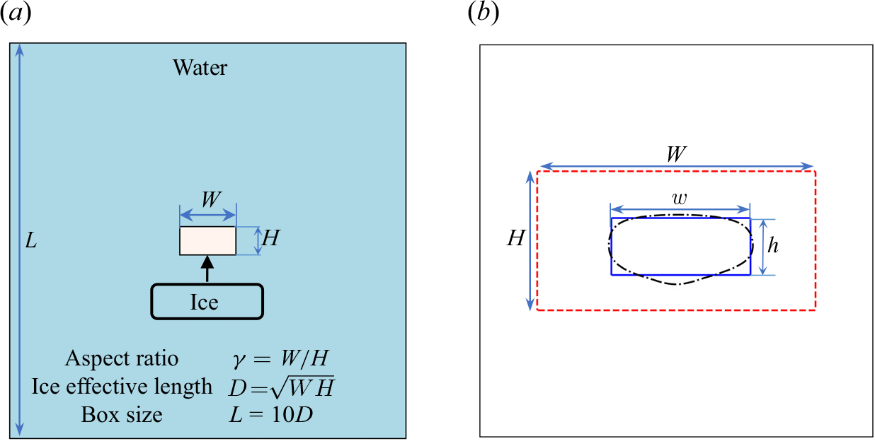
In the simulations, an ice block with an initial cross-sectional area $A_{0}=WH$
is placed at the centre of a square box, as depicted in figure 1(a), where
$A_{0}=WH$
is placed at the centre of a square box, as depicted in figure 1(a), where $W$
and
$W$
and $H$
represent the initial width and height of the ice block, respectively. The box size
$H$
represent the initial width and height of the ice block, respectively. The box size $L$
is set to
$L$
is set to $L=10D$
, where
$L=10D$
, where $D=\sqrt {WH}$
is the effective length of the ice block. As confirmed in Appendix A, the computational domain employed in this study is sufficiently large to ensure that the influence of the side walls on the results is negligible.
$D=\sqrt {WH}$
is the effective length of the ice block. As confirmed in Appendix A, the computational domain employed in this study is sufficiently large to ensure that the influence of the side walls on the results is negligible.
Simulations are performed using the second-order staggered finite difference code AFiD, which has been validated extensively and used to study a wide range of convection problems (Verzicco & Orlandi Reference Verzicco and Orlandi1996; Ostilla-Mónico et al. Reference Ostilla-Mónico, Yang, van der Poel, Lohse and Verzicco2015; van der Poel et al. Reference van der Poel, Ostilla-Mónico, Donners and Verzicco2015), including phase change problems (Liu et al. Reference Liu, Ng, Chong, Lohse and Verzicco2021; Yang et al. Reference Yang, Howland, Liu, Verzicco and Lohse2023, Reference Yang, van den Ham, Verzicco, Lohse and Huisman2024a
,
Reference Yang, Howland, Liu, Verzicco and Lohseb
). The system is governed by four dimensionless control parameters, namely the Rayleigh number ${Ra}$
, the Prandtl number
${Ra}$
, the Prandtl number ${Pr}$
, the Stefan number
${Pr}$
, the Stefan number ${St}$
, and the aspect ratio of the initial ice shape
${St}$
, and the aspect ratio of the initial ice shape $\gamma$
:
$\gamma$
:
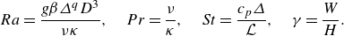 \begin{equation} {Ra}=\frac {g\beta \varDelta ^{q}D^{3}}{\nu \kappa },\quad {Pr}=\frac {\nu }{\kappa },\quad {St}=\frac {c_{p}\varDelta }{\mathcal{L}}, \quad \gamma =\frac {W}{H}. \end{equation}
Here, $\varDelta =T_{w}-T_{i}$
is the initial temperature difference between the ambient water and the ice, where
$\varDelta =T_{w}-T_{i}$
is the initial temperature difference between the ambient water and the ice, where $T_{w}$
is the initial temperature of the ambient water and
$T_{w}$
is the initial temperature of the ambient water and $T_{i}=0^{\,\circ }\mathrm{C}$
is the temperature of the ice. Both two-dimensional (2-D) and three-dimensional (3-D) simulations are performed to examine the effect of aspect ratio on the side, basal and overall melting. In the 3-D simulations, the depth of the ice block is set equal to
$T_{i}=0^{\,\circ }\mathrm{C}$
is the temperature of the ice. Both two-dimensional (2-D) and three-dimensional (3-D) simulations are performed to examine the effect of aspect ratio on the side, basal and overall melting. In the 3-D simulations, the depth of the ice block is set equal to $L$
. All boundaries of the square box are adiabatic, with no-slip conditions for the velocity fields.
$L$
. All boundaries of the square box are adiabatic, with no-slip conditions for the velocity fields.
Since the initial cross-sectional area of the rectangular ice block remains fixed when varying its aspect ratio, the effective length $D$
serves as a representative measure of the initial cross-sectional area, while the aspect ratio
$D$
serves as a representative measure of the initial cross-sectional area, while the aspect ratio $\gamma$
characterises the shape of the ice block. These two governing parameters provide a more suitable description of the system than using the height
$\gamma$
characterises the shape of the ice block. These two governing parameters provide a more suitable description of the system than using the height $H$
and width
$H$
and width $W$
, as in the present study,
$W$
, as in the present study, $H$
and
$H$
and $W$
cannot be varied independently; rather, they are intrinsically linked. Specifically, their values are determined by the effective length of the ice block
$W$
cannot be varied independently; rather, they are intrinsically linked. Specifically, their values are determined by the effective length of the ice block $D$
(i.e. the Rayleigh number
$D$
(i.e. the Rayleigh number ${Ra}$
) and the aspect ratio
${Ra}$
) and the aspect ratio $\gamma$
via the relations
$\gamma$
via the relations $H = D/\sqrt {\gamma }$
and
$H = D/\sqrt {\gamma }$
and $W = D\sqrt {\gamma }$
.
$W = D\sqrt {\gamma }$
.
Due to the extensive parameter space, some control parameters are fixed to ensure the feasibility of this study. The Prandtl number is fixed at ${Pr}=7$
. In § 3, the initial temperature of the surrounding water is fixed at
${Pr}=7$
. In § 3, the initial temperature of the surrounding water is fixed at $T_{w}=20^{\,\circ }\mathrm{C}$
, resulting in a Stefan number
$T_{w}=20^{\,\circ }\mathrm{C}$
, resulting in a Stefan number ${St}=0.25$
. The simulations explore a range
${St}=0.25$
. The simulations explore a range $1.82\times 10^{4}\leqslant {Ra}\leqslant 7.49\times 10^{7}$
, corresponding to the effective ice dimension
$1.82\times 10^{4}\leqslant {Ra}\leqslant 7.49\times 10^{7}$
, corresponding to the effective ice dimension $5 \leqslant D \leqslant 80\, \mathrm{mm}$
. However, in § 4, also the impact of the initial temperature of the surrounding water on the melt rates is investigated at a fixed Rayleigh number
$5 \leqslant D \leqslant 80\, \mathrm{mm}$
. However, in § 4, also the impact of the initial temperature of the surrounding water on the melt rates is investigated at a fixed Rayleigh number ${Ra}=1.46\times 10^{5}$
. The simulations cover a parameter range
${Ra}=1.46\times 10^{5}$
. The simulations cover a parameter range $4^{\,\circ }\mathrm{C}\leqslant T_{w}\leqslant 20^{\,\circ }\mathrm{C}$
, corresponding approximately to the Stefan number
$4^{\,\circ }\mathrm{C}\leqslant T_{w}\leqslant 20^{\,\circ }\mathrm{C}$
, corresponding approximately to the Stefan number $0.05 \leqslant {St} \leqslant 0.25$
. Additionally, the simulations encompass a range
$0.05 \leqslant {St} \leqslant 0.25$
. Additionally, the simulations encompass a range $0.2\leqslant \gamma \leqslant 5.0$
to investigate the aspect ratio effect on the side, basal and overall melt rates.
$0.2\leqslant \gamma \leqslant 5.0$
to investigate the aspect ratio effect on the side, basal and overall melt rates.
Given the highly demanding resolution required to resolve the thin ice–water interface in the phase field, the multiple-resolution strategy (Ostilla-Mónico et al. Reference Ostilla-Mónico, Yang, van der Poel, Lohse and Verzicco2015) is applied for the phase field. For 2-D simulations, an $N\times N$
uniform mesh is used for the velocity and temperature fields, and a
$N\times N$
uniform mesh is used for the velocity and temperature fields, and a $3N\times 3N$
refined uniform mesh is applied for the phase field, where
$3N\times 3N$
refined uniform mesh is applied for the phase field, where $N$
increases from 320 to 5120 as the Rayleigh number increases from
$N$
increases from 320 to 5120 as the Rayleigh number increases from $1.82\times 10^{4}$
to
$1.82\times 10^{4}$
to $7.49\times 10^{7}$
. Grid convergence tests for the 2-D simulations are presented in Appendix A. Due to the high computational cost of the 3-D simulations, only five 3-D cases were performed, namely at
$7.49\times 10^{7}$
. Grid convergence tests for the 2-D simulations are presented in Appendix A. Due to the high computational cost of the 3-D simulations, only five 3-D cases were performed, namely at ${Ra}=1.82\times 10^{4}$
with
${Ra}=1.82\times 10^{4}$
with $\gamma =0.2, \, 0.6,\, 1, \,3, \,5$
, in order to confirm that the qualitative behaviour observed in the 2-D simulations is consistent with that of the 3-D simulations. An
$\gamma =0.2, \, 0.6,\, 1, \,3, \,5$
, in order to confirm that the qualitative behaviour observed in the 2-D simulations is consistent with that of the 3-D simulations. An $N\times N \times N$
uniform mesh is employed for the velocity and temperature fields, and a
$N\times N \times N$
uniform mesh is employed for the velocity and temperature fields, and a $3N\times 3N \times 3N$
refined uniform mesh is applied for the phase field in the 3-D simulations, where
$3N\times 3N \times 3N$
refined uniform mesh is applied for the phase field in the 3-D simulations, where $N=320$
.
$N=320$
.
3. Effect of Rayleigh number for fixed ambient temperature $\boldsymbol{{T}}_{\boldsymbol{w}}=\boldsymbol{20}^{\,\boldsymbol{\circ}}\textbf{C}$

In this section, the ambient temperature is held constant at $T_{w}=20^{\,\circ }\mathrm{C}$
, leading to a Stefan number
$T_{w}=20^{\,\circ }\mathrm{C}$
, leading to a Stefan number ${St}=0.25$
. The Rayleigh number is varied to investigate its influence on the melt rates. We first propose scaling relations for the side and basal mean melt rates, then construct a theoretical model to estimate the overall mean melt rate.
${St}=0.25$
. The Rayleigh number is varied to investigate its influence on the melt rates. We first propose scaling relations for the side and basal mean melt rates, then construct a theoretical model to estimate the overall mean melt rate.
3.1. Scaling relations of the side and basal mean melt rates
An illustration of the procedure for calculating the side and basal mean melt rates is shown in figure 1(b). The steps to calculate the side and basal mean melt rates can be listed as follows. The black dash-dotted contour shown in figure 1(b) indicates the ice shape at the point when $V_{m}=80\,\%$
of the initial area (volume) of the ice block has melted in 2-D (3-D) simulations. Along this ice contour, the side and basal melt points are defined based on the local slope of the contour points. If the local slope
$V_{m}=80\,\%$
of the initial area (volume) of the ice block has melted in 2-D (3-D) simulations. Along this ice contour, the side and basal melt points are defined based on the local slope of the contour points. If the local slope $k$
of a point satisfies
$k$
of a point satisfies $-1\leqslant k\leqslant 1$
, then this point is classified as a basal melt point; otherwise, it is considered as a side melt point. The mean locations of the side and basal melt points are then calculated, and an equivalent rectangle of the ice is formed, represented by the blue solid rectangle in figure 1(b), with width
$-1\leqslant k\leqslant 1$
, then this point is classified as a basal melt point; otherwise, it is considered as a side melt point. The mean locations of the side and basal melt points are then calculated, and an equivalent rectangle of the ice is formed, represented by the blue solid rectangle in figure 1(b), with width $w$
and height
$w$
and height $h$
. Finally, the normalised side melt rate
$h$
. Finally, the normalised side melt rate $\widetilde {f}_{s}$
and the normalised basal melt rate
$\widetilde {f}_{s}$
and the normalised basal melt rate $\widetilde {f}_{b}$
can be defined as
$\widetilde {f}_{b}$
can be defined as
 \begin{equation} \widetilde {f}_{s}=\frac {W-w}{W\widetilde {t}_{m}},\quad \widetilde {f}_{b}=\frac {H-h}{H\widetilde {t}_{m}}. \end{equation}
Here, $\widetilde {t}_{m}=t_{m}/t_{d}$
, where
$\widetilde {t}_{m}=t_{m}/t_{d}$
, where $t_{m}$
denotes the time required to melt
$t_{m}$
denotes the time required to melt $V_{m}=80\,\%$
of the initial area (volume) in 2-D (3-D) simulations, and
$V_{m}=80\,\%$
of the initial area (volume) in 2-D (3-D) simulations, and $t_{d}=D^{2}/\kappa$
is the thermal diffusion time scale. Additionally, the normalised overall mean melt rate
$t_{d}=D^{2}/\kappa$
is the thermal diffusion time scale. Additionally, the normalised overall mean melt rate $\widetilde {f}$
is defined by
$\widetilde {f}$
is defined by $\widetilde {f}=1/\widetilde {t}_{m}=t_{d}/t_{m}$
. It is important to note that different values of the final melt fraction
$\widetilde {f}=1/\widetilde {t}_{m}=t_{d}/t_{m}$
. It is important to note that different values of the final melt fraction $V_{m}$
were also tested for calculating the side mean melt rate
$V_{m}$
were also tested for calculating the side mean melt rate $\widetilde {f}_{s}$
, the basal mean melt rate
$\widetilde {f}_{s}$
, the basal mean melt rate $\widetilde {f}_{b}$
, and the overall mean melt rate
$\widetilde {f}_{b}$
, and the overall mean melt rate $\widetilde {f}$
. While varying the final melt fraction
$\widetilde {f}$
. While varying the final melt fraction $V_{m}$
changes the absolute values of
$V_{m}$
changes the absolute values of $\widetilde {f}_{s}$
,
$\widetilde {f}_{s}$
, $\widetilde {f}_{b}$
and
$\widetilde {f}_{b}$
and $\widetilde {f}$
, the overall trend and scaling relations remain consistent, particularly within the range
$\widetilde {f}$
, the overall trend and scaling relations remain consistent, particularly within the range $60\,\%\leqslant V_{m} \leqslant 80\,\%$
. The temporal evolutions of the side and basal melt rates
$60\,\%\leqslant V_{m} \leqslant 80\,\%$
. The temporal evolutions of the side and basal melt rates $\widetilde {f}_{s}(t)$
and
$\widetilde {f}_{s}(t)$
and $\widetilde {f}_{b}(t)$
are investigated in Appendix B. It is observed that both
$\widetilde {f}_{b}(t)$
are investigated in Appendix B. It is observed that both $\widetilde {f}_{s}(t)$
and
$\widetilde {f}_{s}(t)$
and $\widetilde {f}_{b}(t)$
remain nearly constant over time, particularly when
$\widetilde {f}_{b}(t)$
remain nearly constant over time, particularly when $60\,\%\leqslant V_{m} \leqslant 80\,\%$
, indicating that the choice of the final melt fraction
$60\,\%\leqslant V_{m} \leqslant 80\,\%$
, indicating that the choice of the final melt fraction $V_{m}$
within this range does not affect the qualitative results of this study.
$V_{m}$
within this range does not affect the qualitative results of this study.
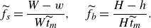
The normalised side mean melt rate $\widetilde {f}_{s}$
and the normalised basal mean melt rate
$\widetilde {f}_{s}$
and the normalised basal mean melt rate $\widetilde {f}_{b}$
as a function of the aspect ratio
$\widetilde {f}_{b}$
as a function of the aspect ratio $\gamma$
for different Rayleigh numbers. The symbols connected by solid lines represent the normalised side mean melt rate
$\gamma$
for different Rayleigh numbers. The symbols connected by solid lines represent the normalised side mean melt rate $\widetilde {f}_{s}$
, and the symbols connected by dashed lines indicate the normalised basal mean melt rate
$\widetilde {f}_{s}$
, and the symbols connected by dashed lines indicate the normalised basal mean melt rate $\widetilde {f}_{b}$
.
$\widetilde {f}_{b}$
.
The normalised side mean melt rate $\widetilde {f}_{s}$
and the normalised basal mean melt rate
$\widetilde {f}_{s}$
and the normalised basal mean melt rate $\widetilde {f}_{b}$
as a function of the aspect ratio
$\widetilde {f}_{b}$
as a function of the aspect ratio $\gamma$
for different Rayleigh numbers are presented in figure 2. The symbols connected by solid lines (for better readability) denote
$\gamma$
for different Rayleigh numbers are presented in figure 2. The symbols connected by solid lines (for better readability) denote $\widetilde {f}_{s}$
, while the symbols connected by dashed lines represent
$\widetilde {f}_{s}$
, while the symbols connected by dashed lines represent $\widetilde {f}_{b}$
. As the aspect ratio
$\widetilde {f}_{b}$
. As the aspect ratio $\gamma$
increases, the side mean melt rate
$\gamma$
increases, the side mean melt rate $\widetilde {f}_{s}$
decreases, whereas the basal mean melt rate
$\widetilde {f}_{s}$
decreases, whereas the basal mean melt rate $\widetilde {f}_{b}$
increases. At
$\widetilde {f}_{b}$
increases. At $\gamma \approx 1.5$
,
$\gamma \approx 1.5$
, $\widetilde {f}_{s}$
and
$\widetilde {f}_{s}$
and $\widetilde {f}_{b}$
converge to similar values. For
$\widetilde {f}_{b}$
converge to similar values. For $\gamma \leqslant 1$
,
$\gamma \leqslant 1$
, $\widetilde {f}_{s}$
exceeds
$\widetilde {f}_{s}$
exceeds $\widetilde {f}_{b}$
, indicating a regime where side melting is dominant. Conversely, for
$\widetilde {f}_{b}$
, indicating a regime where side melting is dominant. Conversely, for $\gamma \geqslant 2$
,
$\gamma \geqslant 2$
, $\widetilde {f}_{b}$
surpasses
$\widetilde {f}_{b}$
surpasses $\widetilde {f}_{s}$
, suggesting a transition to a regime where basal melting becomes dominant.
$\widetilde {f}_{s}$
, suggesting a transition to a regime where basal melting becomes dominant.
(a) The normalised side mean melt rate $\widetilde {f}_{s}$
as function of
$\widetilde {f}_{s}$
as function of ${Ra}$
in the side-melting dominant regime (
${Ra}$
in the side-melting dominant regime ( $\gamma \leqslant 1$
). (b) The compensated normalised side mean melt rate
$\gamma \leqslant 1$
). (b) The compensated normalised side mean melt rate $\widetilde {f}_{s} {Ra}^{-1/4}$
as function of
$\widetilde {f}_{s} {Ra}^{-1/4}$
as function of ${Ra}$
in the side-melting dominant regime (
${Ra}$
in the side-melting dominant regime ( $\gamma \leqslant 1$
). (c) The compensated normalised side mean melt rate
$\gamma \leqslant 1$
). (c) The compensated normalised side mean melt rate $\widetilde {f}_{s} {Ra}^{-1/4}$
as function of
$\widetilde {f}_{s} {Ra}^{-1/4}$
as function of $\gamma$
for different Rayleigh numbers. The yellow region indicates the side-melting dominant regime (
$\gamma$
for different Rayleigh numbers. The yellow region indicates the side-melting dominant regime ( $\gamma \leqslant 1$
).
$\gamma \leqslant 1$
).
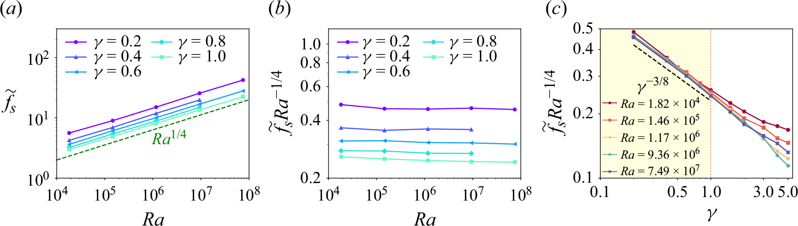
The normalised side mean melt rate $\widetilde {f}_{s}$
as function of
$\widetilde {f}_{s}$
as function of ${Ra}$
in the side-melting dominant regime (
${Ra}$
in the side-melting dominant regime ( $\gamma \leqslant 1$
) is shown in figure 3(a). It is observed that the side mean melt rate
$\gamma \leqslant 1$
) is shown in figure 3(a). It is observed that the side mean melt rate $\widetilde {f}_{s}$
increases with the Rayleigh number. To quantitatively estimate
$\widetilde {f}_{s}$
increases with the Rayleigh number. To quantitatively estimate $\widetilde {f}_{s}$
, we consider the thermal Stefan boundary condition (2.5). According to this boundary condition, the dimensionless instantaneous melt velocity
$\widetilde {f}_{s}$
, we consider the thermal Stefan boundary condition (2.5). According to this boundary condition, the dimensionless instantaneous melt velocity $\widetilde {u}_{n}$
is related to the dimensionless instantaneous heat flux
$\widetilde {u}_{n}$
is related to the dimensionless instantaneous heat flux $ {Nu}$
and the Stefan number
$ {Nu}$
and the Stefan number ${St}$
:
${St}$
:
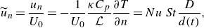 \begin{equation} \widetilde {u}_{n}=\frac {u_{n}}{U_{0}}=-\frac {1}{U_{0}}\frac {\kappa C_{p}}{\mathcal{L}}\frac {\partial T}{\partial n}= {Nu}\, {St} \frac {D}{d(t)}, \end{equation}
where $U_{0}=D/t_{d}$
represents the thermal diffusion velocity scale,
$U_{0}=D/t_{d}$
represents the thermal diffusion velocity scale, ${d} ( t )=\sqrt {A(t)}$
is the effective ice length at time
${d} ( t )=\sqrt {A(t)}$
is the effective ice length at time $t$
,
$t$
, $A(t)$
is the area of the ice at time
$A(t)$
is the area of the ice at time $t$
, and
$t$
, and ${ {Nu}}=- ( \partial T/\partial n )/ ( \varDelta /{d}(t) )$
denotes the Nusselt number. Given that the side mean melt rate
${ {Nu}}=- ( \partial T/\partial n )/ ( \varDelta /{d}(t) )$
denotes the Nusselt number. Given that the side mean melt rate $\widetilde {f}_{s}$
is equal to the time and space average of
$\widetilde {f}_{s}$
is equal to the time and space average of $\widetilde {u}_{n}$
along the side surface of the ice, it follows that
$\widetilde {u}_{n}$
along the side surface of the ice, it follows that $\widetilde {f}_{s}$
must be proportional to the time and space average of the dimensionless heat flux
$\widetilde {f}_{s}$
must be proportional to the time and space average of the dimensionless heat flux $\overline { {Nu}}_{s}$
along the side surface, and also proportional to the Stefan number
$\overline { {Nu}}_{s}$
along the side surface, and also proportional to the Stefan number ${St}$
. In the melting process, the descent of cold meltwater due to thermal buoyancy generates a laminar boundary layer along the side surface of the ice block. Accordingly,
${St}$
. In the melting process, the descent of cold meltwater due to thermal buoyancy generates a laminar boundary layer along the side surface of the ice block. Accordingly, $\overline { {Nu}}_{s}$
can be estimated by the
$\overline { {Nu}}_{s}$
can be estimated by the $\overline { {Nu}}_{s}\propto {Ra}_{H}^{1/4}$
scaling relation for a laminar boundary layer (Bejan Reference Bejan1993; Grossmann & Lohse Reference Grossmann and Lohse2000, Reference Grossmann and Lohse2001; Holman Reference Holman2010), where
$\overline { {Nu}}_{s}\propto {Ra}_{H}^{1/4}$
scaling relation for a laminar boundary layer (Bejan Reference Bejan1993; Grossmann & Lohse Reference Grossmann and Lohse2000, Reference Grossmann and Lohse2001; Holman Reference Holman2010), where ${Ra}_{H}= {Ra} ( H/D )^{3}$
is the Rayleigh number defined by the cross-sectional height
${Ra}_{H}= {Ra} ( H/D )^{3}$
is the Rayleigh number defined by the cross-sectional height $H$
of the ice, and
$H$
of the ice, and $H=D/\sqrt {\gamma }$
. Therefore, the normalised side mean melt rate
$H=D/\sqrt {\gamma }$
. Therefore, the normalised side mean melt rate $\widetilde {f}_{s}$
should follow the scaling relation
$\widetilde {f}_{s}$
should follow the scaling relation
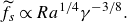 \begin{equation} \widetilde {f}_{s}\propto {Ra}^{1/4}\gamma ^{-3/8}. \end{equation}
This scaling relation is fully consistent with the numerical results: in figure 3(b), the compensated normalised side mean melt rate $\widetilde {f}_{s} {Ra}^{-1/4}$
remains nearly constant across different Rayleigh numbers, confirming the
$\widetilde {f}_{s} {Ra}^{-1/4}$
remains nearly constant across different Rayleigh numbers, confirming the $\widetilde {f}_{s}\propto {Ra}^{1/4}$
scaling relation in the side-melting dominant regime (
$\widetilde {f}_{s}\propto {Ra}^{1/4}$
scaling relation in the side-melting dominant regime ( $\gamma \leqslant 1$
). Furthermore, figure 3(c) shows that the compensated normalised side mean melt rate
$\gamma \leqslant 1$
). Furthermore, figure 3(c) shows that the compensated normalised side mean melt rate $\widetilde {f}_{s} {Ra}^{-1/4}$
nearly collapses for different Rayleigh numbers in the side-melting dominant regime (
$\widetilde {f}_{s} {Ra}^{-1/4}$
nearly collapses for different Rayleigh numbers in the side-melting dominant regime ( $\gamma \leqslant 1$
), and it also follows the
$\gamma \leqslant 1$
), and it also follows the $\gamma ^{-3/8}$
scaling relation when
$\gamma ^{-3/8}$
scaling relation when $\gamma \leqslant 1$
.
$\gamma \leqslant 1$
.
(a) The normalised basal mean melt rate $\widetilde {f}_{b}$
as a function of
$\widetilde {f}_{b}$
as a function of ${Ra}$
in the basal-melting dominant regime (
${Ra}$
in the basal-melting dominant regime ( $\gamma \geqslant 2$
). (b) The compensated normalised basal mean melt rate
$\gamma \geqslant 2$
). (b) The compensated normalised basal mean melt rate $\widetilde {f}_{b} {Ra}^{-1/4}$
as a function of
$\widetilde {f}_{b} {Ra}^{-1/4}$
as a function of ${Ra}$
in the basal-melting dominant regime (
${Ra}$
in the basal-melting dominant regime ( $\gamma \geqslant 2$
). (c) The compensated normalised basal mean melt rate
$\gamma \geqslant 2$
). (c) The compensated normalised basal mean melt rate $\widetilde {f}_{b} {Ra}^{-1/4}$
as a function of
$\widetilde {f}_{b} {Ra}^{-1/4}$
as a function of $\gamma$
for different Rayleigh numbers. The blue region indicates the basal-melting dominant regime (
$\gamma$
for different Rayleigh numbers. The blue region indicates the basal-melting dominant regime ( $\gamma \geqslant 2$
).
$\gamma \geqslant 2$
).
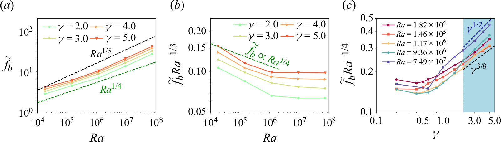
The normalised basal mean melt rate $\widetilde {f}_{b}$
as function of
$\widetilde {f}_{b}$
as function of ${Ra}$
in the basal-melting dominant regime (
${Ra}$
in the basal-melting dominant regime ( $\gamma \geqslant 2$
) is shown in figure 4(a). The normalised basal mean melt rate
$\gamma \geqslant 2$
) is shown in figure 4(a). The normalised basal mean melt rate $\widetilde {f}_{b}$
also increases as the Rayleigh number increases. Since the basal mean melt rate
$\widetilde {f}_{b}$
also increases as the Rayleigh number increases. Since the basal mean melt rate $\widetilde {f}_{b}$
is equal to the time average of
$\widetilde {f}_{b}$
is equal to the time average of $\widetilde {u}_{n}$
along the basal surface of the ice, according to (3.2),
$\widetilde {u}_{n}$
along the basal surface of the ice, according to (3.2), $\widetilde {f}_{b}$
should be proportional to the time and space average of the dimensionless heat flux
$\widetilde {f}_{b}$
should be proportional to the time and space average of the dimensionless heat flux $\overline { {Nu}}_{b}$
along the basal surface, and also proportional to the Stefan number
$\overline { {Nu}}_{b}$
along the basal surface, and also proportional to the Stefan number ${St}$
. For low Rayleigh numbers (
${St}$
. For low Rayleigh numbers ( ${Ra}\leqslant 10^{6}$
), a laminar boundary layer forms around the basal surface of the ice block, with the mean heat flux along the basal surface following the
${Ra}\leqslant 10^{6}$
), a laminar boundary layer forms around the basal surface of the ice block, with the mean heat flux along the basal surface following the $\overline { {Nu}}_{b}\propto {Ra}_{W}^{1/4}$
scaling relation for a laminar boundary layer (Bejan Reference Bejan1993; Grossmann & Lohse Reference Grossmann and Lohse2000, Reference Grossmann and Lohse2001; Holman Reference Holman2010), where
$\overline { {Nu}}_{b}\propto {Ra}_{W}^{1/4}$
scaling relation for a laminar boundary layer (Bejan Reference Bejan1993; Grossmann & Lohse Reference Grossmann and Lohse2000, Reference Grossmann and Lohse2001; Holman Reference Holman2010), where ${Ra}_{W}= {Ra} ( W/D )^{3}$
is the Rayleigh number defined by the cross-sectional width
${Ra}_{W}= {Ra} ( W/D )^{3}$
is the Rayleigh number defined by the cross-sectional width $W$
of the ice, and
$W$
of the ice, and $W=D\sqrt {\gamma }$
. Consequently, the normalised basal mean melt rate
$W=D\sqrt {\gamma }$
. Consequently, the normalised basal mean melt rate $\widetilde {f}_{b}$
should follow the scaling relation
$\widetilde {f}_{b}$
should follow the scaling relation
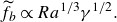
 \begin{equation} \widetilde {f}_{b}\propto {Ra}^{1/4}\gamma ^{3/8}. \end{equation}
This scaling relation is consistent with the numerical results. In figure 4(b), the compensated normalised basal mean melt rate $\widetilde {f}_{b} {Ra}^{-1/4}$
is almost constant for
$\widetilde {f}_{b} {Ra}^{-1/4}$
is almost constant for ${Ra}\leqslant 10^{6}$
, particularly for
${Ra}\leqslant 10^{6}$
, particularly for $\gamma \geqslant 3$
where the basal melt rate significantly exceeds the side melt rate. This confirms that the basal mean melt rate
$\gamma \geqslant 3$
where the basal melt rate significantly exceeds the side melt rate. This confirms that the basal mean melt rate $\widetilde {f}_{b}$
follows an
$\widetilde {f}_{b}$
follows an $\widetilde {f}_{b}\propto {Ra}^{1/4}$
scaling relation in the basal-melting dominant regime (
$\widetilde {f}_{b}\propto {Ra}^{1/4}$
scaling relation in the basal-melting dominant regime ( $\gamma \geqslant 2$
) at low Rayleigh numbers. Moreover, figure 4(c) indicates that the compensated normalised basal mean melt rate
$\gamma \geqslant 2$
) at low Rayleigh numbers. Moreover, figure 4(c) indicates that the compensated normalised basal mean melt rate $\widetilde {f}_{b} {Ra}^{-1/4}$
adheres to the
$\widetilde {f}_{b} {Ra}^{-1/4}$
adheres to the $\gamma ^{3/8}$
scaling relation in the basal-melting dominant regime (
$\gamma ^{3/8}$
scaling relation in the basal-melting dominant regime ( $\gamma \geqslant 2$
) when
$\gamma \geqslant 2$
) when ${Ra}\leqslant 10^{6}$
.
${Ra}\leqslant 10^{6}$
.
For sufficiently high Rayleigh numbers ( ${Ra}\gt 10^{6}$
), figure 4(b) reveals a transition in the scaling relation of the normalised basal mean melt rate
${Ra}\gt 10^{6}$
), figure 4(b) reveals a transition in the scaling relation of the normalised basal mean melt rate $\widetilde {f}_{b}$
: the scaling relation shifts from
$\widetilde {f}_{b}$
: the scaling relation shifts from ${Ra}^{1/4}$
to
${Ra}^{1/4}$
to ${Ra}^{1/3}$
when
${Ra}^{1/3}$
when ${Ra}\gt 10^{6}$
. This transition indicates that while the boundary layer remains laminar, the bulk flow around the base of the ice block undergoes a transition from laminar to turbulent, with the mean heat flux along the basal surface following the
${Ra}\gt 10^{6}$
. This transition indicates that while the boundary layer remains laminar, the bulk flow around the base of the ice block undergoes a transition from laminar to turbulent, with the mean heat flux along the basal surface following the $\overline { {Nu}}_{b} \propto {Ra}_{W}^{1/3}$
scaling relation characteristic of the turbulent bulk flow with a laminar boundary layer (Bejan Reference Bejan1993; Grossmann & Lohse Reference Grossmann and Lohse2000, Reference Grossmann and Lohse2001; Holman Reference Holman2010). Accordingly, the scaling relation of the normalised basal mean melt rate
$\overline { {Nu}}_{b} \propto {Ra}_{W}^{1/3}$
scaling relation characteristic of the turbulent bulk flow with a laminar boundary layer (Bejan Reference Bejan1993; Grossmann & Lohse Reference Grossmann and Lohse2000, Reference Grossmann and Lohse2001; Holman Reference Holman2010). Accordingly, the scaling relation of the normalised basal mean melt rate $\widetilde {f}_{b}$
adjusts to
$\widetilde {f}_{b}$
adjusts to
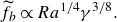
 \begin{equation} \widetilde {f}_{b}\propto {Ra}^{1/3}\gamma ^{1/2}. \end{equation}
This scaling relation is consistent with the numerical results shown in figure 4(c), where $\widetilde {f}_{b}$
adheres to the
$\widetilde {f}_{b}$
adheres to the $\gamma ^{1/2}$
scaling relation in the basal-melting dominant regime (
$\gamma ^{1/2}$
scaling relation in the basal-melting dominant regime ( $\gamma \geqslant 2$
) when
$\gamma \geqslant 2$
) when ${Ra}\gt 10^{6}$
.
${Ra}\gt 10^{6}$
.
(a–c) The instantaneous temperature field at time $t/t_{m}=0.7$
for the ice block with (a)
$t/t_{m}=0.7$
for the ice block with (a) $\gamma =0.2$
, (b)
$\gamma =0.2$
, (b) $\gamma =1.0$
and (c)
$\gamma =1.0$
and (c) $\gamma =5.0$
at
$\gamma =5.0$
at ${Ra}=7.49\times 10^{7}$
. The dimensionless instantaneous heat fluxes
${Ra}=7.49\times 10^{7}$
. The dimensionless instantaneous heat fluxes $ {Nu}$
around the ice surface are 3.47, 2.22 and 3.22 in (a), (b) and (c), respectively. (d) The
$ {Nu}$
around the ice surface are 3.47, 2.22 and 3.22 in (a), (b) and (c), respectively. (d) The ${Ra}$
–
${Ra}$
– $\gamma$
phase diagram of cavity formation. Black disks and red squares indicate the absence and presence of cavity formation, respectively. The yellow region represents the side-melting dominant regime, and the blue region denotes the basal-melting dominant regime.
$\gamma$
phase diagram of cavity formation. Black disks and red squares indicate the absence and presence of cavity formation, respectively. The yellow region represents the side-melting dominant regime, and the blue region denotes the basal-melting dominant regime.
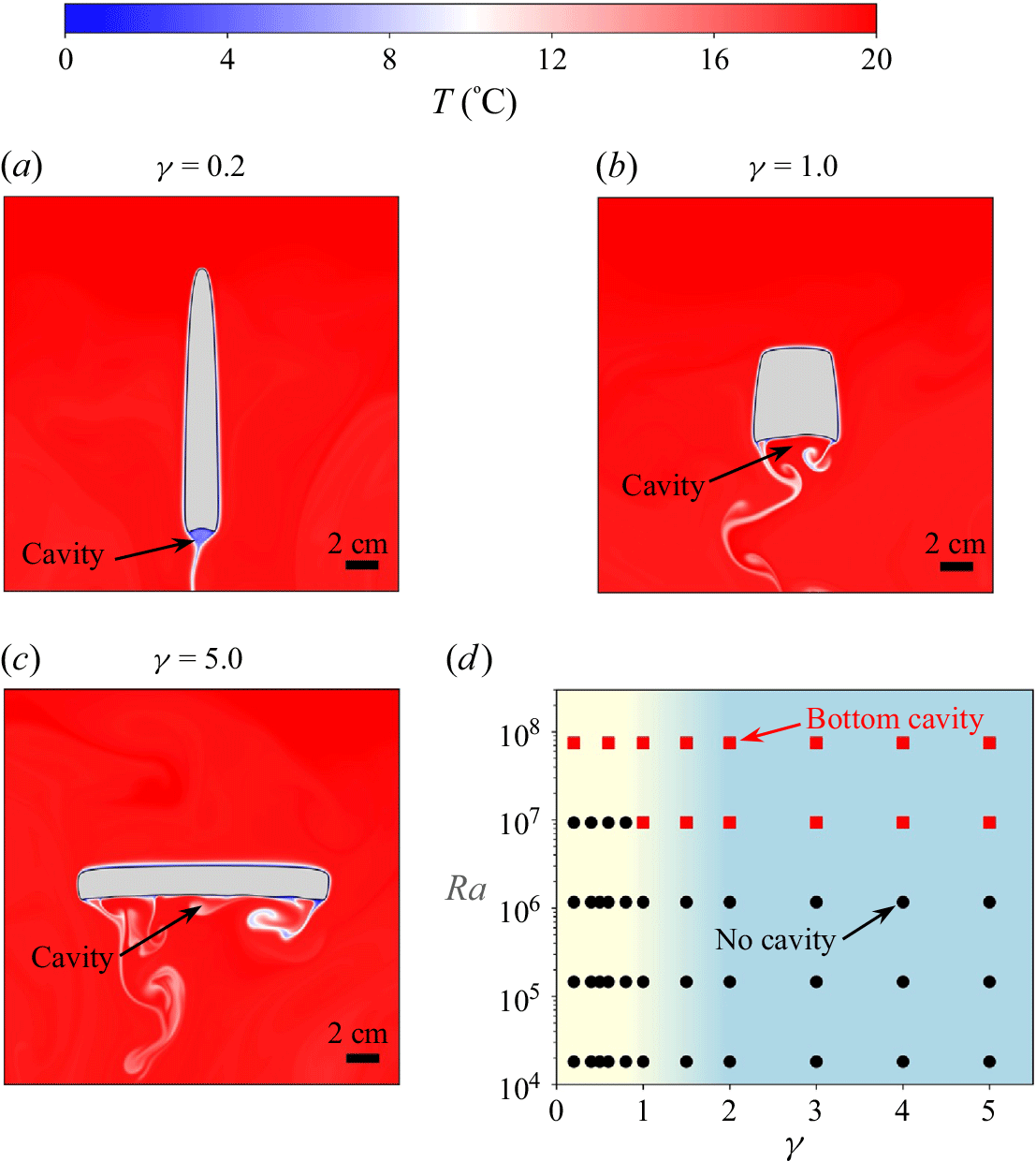
The observed scaling transition is due primarily to the formation of a cavity at the bottom of the ice block, as illustrated in figure 5(a–c). Figure 5(a–c) display the instantaneous temperature field for the ice block with various $\gamma$
values. The formation of the bottom cavity is attributed to the flow separation. At sufficiently high Rayleigh numbers, the descending meltwater along the side surface of the ice block detaches before reaching the base, leading to the development of convection rolls in the bottom region. These convection rolls enhance local mixing, thereby increasing the local heat flux and melt rate, and ultimately contributing to the cavity formation. While the boundary layer along the basal surface remains laminar, the bulk flow in the bottom region transitions to turbulence due to the cavity formation. This triggers the scaling transition of the normalised basal mean melt rate
$\gamma$
values. The formation of the bottom cavity is attributed to the flow separation. At sufficiently high Rayleigh numbers, the descending meltwater along the side surface of the ice block detaches before reaching the base, leading to the development of convection rolls in the bottom region. These convection rolls enhance local mixing, thereby increasing the local heat flux and melt rate, and ultimately contributing to the cavity formation. While the boundary layer along the basal surface remains laminar, the bulk flow in the bottom region transitions to turbulence due to the cavity formation. This triggers the scaling transition of the normalised basal mean melt rate $\widetilde {f}_{b}$
to
$\widetilde {f}_{b}$
to ${Ra}^{1/3}$
. Additionally, the dimensionless instantaneous heat flux
${Ra}^{1/3}$
. Additionally, the dimensionless instantaneous heat flux $ {Nu}$
around the ice surface for the ice block with
$ {Nu}$
around the ice surface for the ice block with $\gamma =1.0$
is smaller compared to values for the ice blocks with
$\gamma =1.0$
is smaller compared to values for the ice blocks with $\gamma =0.2$
and
$\gamma =0.2$
and $\gamma = 5.0$
, implying that the ice block with
$\gamma = 5.0$
, implying that the ice block with $\gamma = 1.0$
undergoes a slower melt rate compared to the ice blocks with
$\gamma = 1.0$
undergoes a slower melt rate compared to the ice blocks with $\gamma = 0.2$
and
$\gamma = 0.2$
and $\gamma = 5.0$
.
$\gamma = 5.0$
.
Figure 5(d) shows the ${Ra}$
–
${Ra}$
– $\gamma$
phase diagram for cavity formation, showing that the bottom cavity forms at either high
$\gamma$
phase diagram for cavity formation, showing that the bottom cavity forms at either high $\gamma$
values or high
$\gamma$
values or high ${Ra}$
values. At
${Ra}$
values. At ${Ra} = 9.36 \times 10^6$
, the cavity appears only when
${Ra} = 9.36 \times 10^6$
, the cavity appears only when $\gamma \geqslant 1$
; however, as the Rayleigh number increases to
$\gamma \geqslant 1$
; however, as the Rayleigh number increases to $7.49 \times 10^7$
, the cavity forms for all
$7.49 \times 10^7$
, the cavity forms for all $\gamma$
values. The regime transition associated with cavity formation is fully consistent with the corresponding scaling transition in the basal mean melt rate
$\gamma$
values. The regime transition associated with cavity formation is fully consistent with the corresponding scaling transition in the basal mean melt rate $\widetilde {f}_{b}$
. In the basal-melting dominant regime (
$\widetilde {f}_{b}$
. In the basal-melting dominant regime ( $\gamma \geqslant 2$
), the cavity forms when
$\gamma \geqslant 2$
), the cavity forms when ${Ra} \geqslant 9.36 \times 10^6$
, leading to the scaling transition of
${Ra} \geqslant 9.36 \times 10^6$
, leading to the scaling transition of $\widetilde {f}_{b}$
to
$\widetilde {f}_{b}$
to ${Ra}^{1/3}$
, as shown in figure 4(b). The intensified local melt rate within the cavity significantly enhances the basal mean melt rate
${Ra}^{1/3}$
, as shown in figure 4(b). The intensified local melt rate within the cavity significantly enhances the basal mean melt rate $\widetilde {f}_{b}$
, leading to the scaling transition. Due to the observation that the cavity is more readily formed at higher values of
$\widetilde {f}_{b}$
, leading to the scaling transition. Due to the observation that the cavity is more readily formed at higher values of $\gamma$
, it can be inferred that the critical Rayleigh number for the scaling transition of
$\gamma$
, it can be inferred that the critical Rayleigh number for the scaling transition of $\widetilde {f}_{b}$
from
$\widetilde {f}_{b}$
from $\operatorname { {Ra}}^{1/4}\gamma ^{3/8}$
to
$\operatorname { {Ra}}^{1/4}\gamma ^{3/8}$
to $\operatorname { {Ra}}^{1/3}\gamma ^{1/2}$
is smaller for larger
$\operatorname { {Ra}}^{1/3}\gamma ^{1/2}$
is smaller for larger $\gamma$
. To accurately determine the critical Rayleigh number, more data with different Rayleigh numbers and initial aspect ratios are required, which is beyond the scope of the present study.
$\gamma$
. To accurately determine the critical Rayleigh number, more data with different Rayleigh numbers and initial aspect ratios are required, which is beyond the scope of the present study.
3.2. Estimation of the overall mean melt rate
The compensated normalised overall mean melt rate $\widetilde {f} {Ra}^{-1/4}$
as a function of
$\widetilde {f} {Ra}^{-1/4}$
as a function of $\gamma$
for different Rayleigh numbers. The symbols represent the compensated normalised overall mean melt rates
$\gamma$
for different Rayleigh numbers. The symbols represent the compensated normalised overall mean melt rates $\widetilde {f} {Ra}^{-1/4}$
. Two green dashed lines represent the theoretical predictions from (3.12) for the overall mean melt rates
$\widetilde {f} {Ra}^{-1/4}$
. Two green dashed lines represent the theoretical predictions from (3.12) for the overall mean melt rates $\widetilde {f} {Ra}^{-1/4}$
at
$\widetilde {f} {Ra}^{-1/4}$
at ${Ra}=1.46\times 10^{5}$
and
${Ra}=1.46\times 10^{5}$
and $1.17\times 10^{6}$
, respectively. Similarly, two grey dashed lines denote the theoretical predictions from (3.14) for the overall mean melt rates
$1.17\times 10^{6}$
, respectively. Similarly, two grey dashed lines denote the theoretical predictions from (3.14) for the overall mean melt rates $\widetilde {f} {Ra}^{-1/4}$
at
$\widetilde {f} {Ra}^{-1/4}$
at ${Ra}=9.36\times 10^{6}$
and
${Ra}=9.36\times 10^{6}$
and $7.49\times 10^{7}$
, respectively.
$7.49\times 10^{7}$
, respectively.
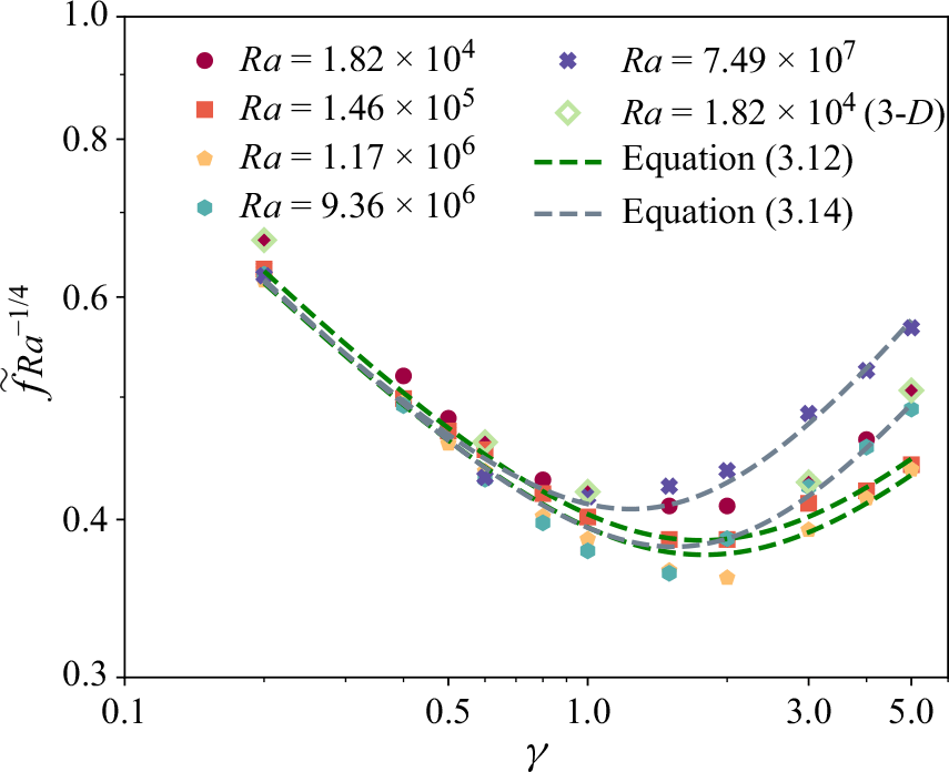
Figure 6 presents the compensated normalised overall mean melt rate $\widetilde {f} {Ra}^{-1/4}$
as function of
$\widetilde {f} {Ra}^{-1/4}$
as function of $\gamma$
for various Rayleigh numbers. Five 3-D simulations were also performed. It is found that the overall mean melt rates
$\gamma$
for various Rayleigh numbers. Five 3-D simulations were also performed. It is found that the overall mean melt rates $\widetilde {f}$
in 3-D simulations are nearly identical to those in corresponding 2-D simulations, demonstrating qualitative consistency between 2-D and 3-D results. Due to the more comprehensive data available in 2-D simulations compared to 3-D simulations, however, our analysis focuses primarily on the 2-D simulations.
$\widetilde {f}$
in 3-D simulations are nearly identical to those in corresponding 2-D simulations, demonstrating qualitative consistency between 2-D and 3-D results. Due to the more comprehensive data available in 2-D simulations compared to 3-D simulations, however, our analysis focuses primarily on the 2-D simulations.
As the overall mean melt rate $\widetilde {f}$
depends on both
$\widetilde {f}$
depends on both ${Ra}$
and
${Ra}$
and $\gamma$
, the compensated normalised overall mean melt rate
$\gamma$
, the compensated normalised overall mean melt rate $\widetilde {f} {Ra}^{-1/4}$
is used to make the curves for different
$\widetilde {f} {Ra}^{-1/4}$
is used to make the curves for different ${Ra}$
comparable. The results show that
${Ra}$
comparable. The results show that $\widetilde {f} {Ra}^{-1/4}$
collapses at
$\widetilde {f} {Ra}^{-1/4}$
collapses at $\gamma \leqslant 0.6$
, especially for
$\gamma \leqslant 0.6$
, especially for ${Ra} \geqslant 1.46\times 10^{5}$
. This phenomenon can be attributed to the dominance of side melting when
${Ra} \geqslant 1.46\times 10^{5}$
. This phenomenon can be attributed to the dominance of side melting when $\gamma \leqslant 0.6$
, where the side mean melt rate
$\gamma \leqslant 0.6$
, where the side mean melt rate $\widetilde {f}_{s}$
significantly exceeds the basal mean melt rate
$\widetilde {f}_{s}$
significantly exceeds the basal mean melt rate $\widetilde {f}_{b}$
(figure 2). As figure 3(b) illustrates, the side mean melt rate
$\widetilde {f}_{b}$
(figure 2). As figure 3(b) illustrates, the side mean melt rate $\widetilde {f}_{s}$
adheres to the
$\widetilde {f}_{s}$
adheres to the ${Ra}^{1/4}$
scaling relation in the side-melting dominant regime, leading to the
${Ra}^{1/4}$
scaling relation in the side-melting dominant regime, leading to the ${Ra}^{1/4}$
scaling relation for the overall mean melt rate
${Ra}^{1/4}$
scaling relation for the overall mean melt rate $\widetilde {f}$
at
$\widetilde {f}$
at $\gamma \leqslant 0.6$
.
$\gamma \leqslant 0.6$
.
The overall mean melt rate exhibits a non-monotonic dependence on the aspect ratio $\gamma$
: the overall mean melt rate
$\gamma$
: the overall mean melt rate $\widetilde {f}$
initially decreases and then increases with increasing
$\widetilde {f}$
initially decreases and then increases with increasing $\gamma$
. This non-monotonic behaviour results from the competition between side and basal melting. For
$\gamma$
. This non-monotonic behaviour results from the competition between side and basal melting. For $\gamma \leqslant 1$
, side melting is dominant, and
$\gamma \leqslant 1$
, side melting is dominant, and $\widetilde {f}_{s}$
decreases as
$\widetilde {f}_{s}$
decreases as $\gamma$
increases (figure 2), leading to a decrease of the overall mean melt rate
$\gamma$
increases (figure 2), leading to a decrease of the overall mean melt rate $\widetilde {f}$
with increasing
$\widetilde {f}$
with increasing $\gamma$
. Conversely, for
$\gamma$
. Conversely, for $\gamma \geqslant 2$
, basal melting dominates, and
$\gamma \geqslant 2$
, basal melting dominates, and $\widetilde {f}_{b}$
increases as
$\widetilde {f}_{b}$
increases as $\gamma$
increases (figure 2), resulting in an increase of the overall mean melt rate
$\gamma$
increases (figure 2), resulting in an increase of the overall mean melt rate $\widetilde {f}$
with increasing
$\widetilde {f}$
with increasing $\gamma$
.
$\gamma$
.
The minimum overall mean melt rate occurs at aspect ratio $\gamma _{{min}}\approx 2$
when
$\gamma _{{min}}\approx 2$
when ${Ra} \leqslant 1.17\times 10^{6}$
. The value of
${Ra} \leqslant 1.17\times 10^{6}$
. The value of $\gamma _{{min}}$
deviates from
$\gamma _{{min}}$
deviates from $\gamma =1$
, the configuration where the square-shaped ice block has the smallest perimeter. This reflects that the influence of thermal convection plays a more dominant role in determining the minimum overall melt rate compared to the geometric effect of surface area alone. However, as
$\gamma =1$
, the configuration where the square-shaped ice block has the smallest perimeter. This reflects that the influence of thermal convection plays a more dominant role in determining the minimum overall melt rate compared to the geometric effect of surface area alone. However, as ${Ra}$
further increases beyond
${Ra}$
further increases beyond ${Ra} \geqslant 9.36\times 10^{6}$
,
${Ra} \geqslant 9.36\times 10^{6}$
, $\gamma _{{min}}$
begins to decrease. This decrease of
$\gamma _{{min}}$
begins to decrease. This decrease of $\gamma _{{min}}$
is due mainly to the scaling transition of the basal mean melt rate
$\gamma _{{min}}$
is due mainly to the scaling transition of the basal mean melt rate $\widetilde {f}_{b}$
. For
$\widetilde {f}_{b}$
. For ${Ra} \geqslant 9.36\times 10^{6}$
, the
${Ra} \geqslant 9.36\times 10^{6}$
, the ${Ra}$
scaling relation of
${Ra}$
scaling relation of $\widetilde {f}_{b}$
transitions from
$\widetilde {f}_{b}$
transitions from ${Ra}^{1/4}$
to
${Ra}^{1/4}$
to ${Ra}^{1/3}$
(figure 4
b), and similarly, the
${Ra}^{1/3}$
(figure 4
b), and similarly, the $\gamma$
scaling relation of
$\gamma$
scaling relation of $\widetilde {f}_{b}$
shifts from
$\widetilde {f}_{b}$
shifts from $\gamma ^{3/8}$
to
$\gamma ^{3/8}$
to $\gamma ^{1/2}$
(figure 4
c) due to cavity formation. Consequently, the intensity of the basal mean melt rate
$\gamma ^{1/2}$
(figure 4
c) due to cavity formation. Consequently, the intensity of the basal mean melt rate $\widetilde {f}_{b}$
is significantly enhanced at higher Rayleigh numbers, causing
$\widetilde {f}_{b}$
is significantly enhanced at higher Rayleigh numbers, causing $\gamma _{{min}}$
to decrease at sufficiently high Rayleigh numbers.
$\gamma _{{min}}$
to decrease at sufficiently high Rayleigh numbers.
Our observations reveal that the aspect ratio $\gamma$
of the initial ice shape significantly affects the overall mean melt rate, with the ratio of the maximum to the minimum overall mean melt rates at the same Rayleigh number reaching up to 1.7. However, this aspect ratio effect has often been neglected in previous models for estimating the melt rates of icebergs (Weeks & Campbell Reference Weeks and Campbell1973; Martin & Adcroft Reference Martin and Adcroft2010), potentially compromising their accuracy. Therefore, it is crucial to incorporate the aspect ratio effect into models for estimating iceberg melt rates to enhance their accuracy.
$\gamma$
of the initial ice shape significantly affects the overall mean melt rate, with the ratio of the maximum to the minimum overall mean melt rates at the same Rayleigh number reaching up to 1.7. However, this aspect ratio effect has often been neglected in previous models for estimating the melt rates of icebergs (Weeks & Campbell Reference Weeks and Campbell1973; Martin & Adcroft Reference Martin and Adcroft2010), potentially compromising their accuracy. Therefore, it is crucial to incorporate the aspect ratio effect into models for estimating iceberg melt rates to enhance their accuracy.
Based on the previous scaling relations for the side mean melt rate $\widetilde {f}_{b}$
(3.3) and the basal mean melt rate
$\widetilde {f}_{b}$
(3.3) and the basal mean melt rate $\widetilde {f}_{s}$
in (3.4) or (3.5), the theoretical model for the overall mean melt rate
$\widetilde {f}_{s}$
in (3.4) or (3.5), the theoretical model for the overall mean melt rate $\widetilde {f}$
can be proposed as follows. As depicted in figure 1(b), the area of the equivalent ice rectangle, represented by the blue solid rectangle with width
$\widetilde {f}$
can be proposed as follows. As depicted in figure 1(b), the area of the equivalent ice rectangle, represented by the blue solid rectangle with width $w$
and height
$w$
and height $h$
, is approximately
$h$
, is approximately $1-V_{m}$
of the initial area of the ice block shown by the red dashed rectangle, which gives
$1-V_{m}$
of the initial area of the ice block shown by the red dashed rectangle, which gives
 \begin{equation} hw=\left ( 1-V_{m} \right )HW, \end{equation}
where $V_{m}=80\,\%$
in this study. Through some rewriting (3.6) becomes
$V_{m}=80\,\%$
in this study. Through some rewriting (3.6) becomes
 \begin{equation} V_{m}-\frac {W-w}{W}-\frac {H-h}{H}+\frac {\left ( W-w \right )\left ( H-h \right )}{WH}=0. \end{equation}
Upon dividing both sides of (3.7) by ${\widetilde {t}_{\,m}}^{\,2}$
, the following equation is obtained:
${\widetilde {t}_{\,m}}^{\,2}$
, the following equation is obtained:
 \begin{equation} \frac {V_{m}}{{\widetilde {t}_{\,m}}^{\,2}}-\frac {W-w}{W{\widetilde {t}_{\,m}}^{\,2}}-\frac {H-h}{H{\widetilde {t}_{\,m}}^{\,2}}+\frac {\left ( W-w \right )\left ( H-h \right )}{WH{\widetilde {t}_{\,m}}^{\,2}}=0. \end{equation}
By substituting the definitions of the side mean melt rate $\widetilde {f}_{s}$
and the basal mean melt rate
$\widetilde {f}_{s}$
and the basal mean melt rate $\widetilde {f}_{b}$
from (3.1), as well as the overall mean melt rate
$\widetilde {f}_{b}$
from (3.1), as well as the overall mean melt rate $\widetilde {f}=1/\widetilde {t}_{m}$
, into (3.8), we obtain
$\widetilde {f}=1/\widetilde {t}_{m}$
, into (3.8), we obtain
 \begin{equation} V_{m}\widetilde {f}^{\,2}-\left ( \widetilde {f}_{s} +\widetilde {f}_{b}\right )\widetilde {f}+\widetilde {f}_{s}\, \widetilde {f}_{b}=0. \end{equation}
Therefore, the overall mean melt rate $\widetilde {f}$
can be expressed as
$\widetilde {f}$
can be expressed as
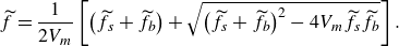 \begin{equation} \widetilde {f}=\frac {1}{2V_{m}}\left [ \left ( \widetilde {f}_{s}+\widetilde {f}_{b} \right )+\sqrt {\left ( \widetilde {f}_{s}+\widetilde {f}_{b}\right )^{2}-4V_{m}\widetilde {f}_{s}\widetilde {f}_{b} } \right ]. \end{equation}
For low Rayleigh numbers ( ${Ra}\leqslant 10^{6}$
), the side and basal mean melt rates
${Ra}\leqslant 10^{6}$
), the side and basal mean melt rates $\widetilde {f}_{s}$
and
$\widetilde {f}_{s}$
and $\widetilde {f}_{b}$
can be estimated using the scaling relations given by (3.3) and (3.4), respectively:
$\widetilde {f}_{b}$
can be estimated using the scaling relations given by (3.3) and (3.4), respectively:
 \begin{equation} \widetilde {f}_{s}= a_{s}\gamma ^{-3/8},\quad\widetilde {f}_{b}= a_{b1}\gamma ^{3/8}, \end{equation}
where $a_{s}$
and
$a_{s}$
and $a_{b1}$
are the coefficients of the scaling relations for the side and basal mean melt rates, respectively. By substituting (3.11) into (3.10), we obtain
$a_{b1}$
are the coefficients of the scaling relations for the side and basal mean melt rates, respectively. By substituting (3.11) into (3.10), we obtain
 \begin{equation} \widetilde {f}\propto \left ( \gamma ^{-3/8}+a_{1}\gamma ^{3/8} \right )+\sqrt {\left ( \gamma ^{-3/8}+a_{1}\gamma ^{3/8} \right )^{2}-4V_{m}a_{1}}, \end{equation}
where $a_{1}=a_{b1}/a_{s}$
is the ratio of the coefficients of the scaling relations for the side and basal mean melt rates, which can be determined by fitting.
$a_{1}=a_{b1}/a_{s}$
is the ratio of the coefficients of the scaling relations for the side and basal mean melt rates, which can be determined by fitting.
For sufficiently high Rayleigh numbers ( ${Ra}\gt 10^{6}$
), the side and basal mean melt rates
${Ra}\gt 10^{6}$
), the side and basal mean melt rates $\widetilde {f}_{s}$
and
$\widetilde {f}_{s}$
and $\widetilde {f}_{b}$
are estimated by the scaling relations in (3.3) and (3.5), respectively:
$\widetilde {f}_{b}$
are estimated by the scaling relations in (3.3) and (3.5), respectively:
 \begin{equation} \widetilde {f}_{s}= a_{s}\gamma ^{-3/8},\quad\widetilde {f}_{b}= a_{b2}\gamma ^{1/2}, \end{equation}
where $a_{s}$
and
$a_{s}$
and $a_{b2}$
are the coefficients of the scaling relations for the side and basal mean melt rates, respectively. By substituting (3.13) into (3.10), we get
$a_{b2}$
are the coefficients of the scaling relations for the side and basal mean melt rates, respectively. By substituting (3.13) into (3.10), we get
 \begin{equation} \widetilde {f}\propto \left ( \gamma ^{-3/8}+a_{2}\gamma ^{1/2} \right )+\sqrt {\left ( \gamma ^{-3/8}+a_{2}\gamma ^{1/2} \right )^{2}-4V_{m}a_{2}\gamma ^{1/8}}, \end{equation}
where $a_{2}=a_{b2}/a_{s}$
is the ratio of the coefficients of the scaling relations for the side and basal mean melt rates, which can be obtained by fitting from the data.
$a_{2}=a_{b2}/a_{s}$
is the ratio of the coefficients of the scaling relations for the side and basal mean melt rates, which can be obtained by fitting from the data.
In order to derive the theoretical model for the overall mean melt rate $\widetilde {f}$
in (3.12) and (3.14), an assumption should be made that the scaling relations for
$\widetilde {f}$
in (3.12) and (3.14), an assumption should be made that the scaling relations for $\widetilde {f}_{s}$
and
$\widetilde {f}_{s}$
and $\widetilde {f}_{b}$
in (3.11) and (3.13) hold for all values of
$\widetilde {f}_{b}$
in (3.11) and (3.13) hold for all values of $\gamma$
. However, this assumption does not apply universally. The scaling relation of
$\gamma$
. However, this assumption does not apply universally. The scaling relation of $\widetilde {f}_{s}$
is valid only in the side-melting dominant regime, as shown in figure 3(c), while the scaling relation of
$\widetilde {f}_{s}$
is valid only in the side-melting dominant regime, as shown in figure 3(c), while the scaling relation of $\widetilde {f}_{b}$
is accurate only in the basal-melting dominant regime, as depicted in figure 4(c). Therefore, we can infer that the invalidity of the assumption has a small impact on the theoretical model in the side- and basal-melting dominant regimes because the basal mean melt rate
$\widetilde {f}_{b}$
is accurate only in the basal-melting dominant regime, as depicted in figure 4(c). Therefore, we can infer that the invalidity of the assumption has a small impact on the theoretical model in the side- and basal-melting dominant regimes because the basal mean melt rate $\widetilde {f}_{b}$
is small in the side-melting dominant regime, and the side mean melt rate
$\widetilde {f}_{b}$
is small in the side-melting dominant regime, and the side mean melt rate $\widetilde {f}_{s}$
is small in the basal-melting dominant regime (figure 2). However, the proposed theoretical model obviously fails in the intermediate region where both side and basal mean melt rates significantly contribute to the overall mean melt rate.
$\widetilde {f}_{s}$
is small in the basal-melting dominant regime (figure 2). However, the proposed theoretical model obviously fails in the intermediate region where both side and basal mean melt rates significantly contribute to the overall mean melt rate.
Figure 6 illustrates the behaviour of the proposed theoretical model for the overall mean melt rate $\widetilde {f}$
in (3.12) and (3.14). Two green dashed lines represent the theoretical predictions from (3.12) for the overall mean melt rates
$\widetilde {f}$
in (3.12) and (3.14). Two green dashed lines represent the theoretical predictions from (3.12) for the overall mean melt rates $\widetilde {f} {Ra}^{-1/4}$
at
$\widetilde {f} {Ra}^{-1/4}$
at ${Ra}=1.46\times 10^{5}$
and
${Ra}=1.46\times 10^{5}$
and $1.17\times 10^{6}$
, respectively. Similarly, two grey dashed lines denote the theoretical predictions from (3.14) for the overall mean melt rates
$1.17\times 10^{6}$
, respectively. Similarly, two grey dashed lines denote the theoretical predictions from (3.14) for the overall mean melt rates $\widetilde {f} {Ra}^{-1/4}$
at
$\widetilde {f} {Ra}^{-1/4}$
at ${Ra}=9.36\times 10^{6}$
and
${Ra}=9.36\times 10^{6}$
and $7.49\times 10^{7}$
, respectively. The theoretical model successfully captures the non-monotonic behaviour of
$7.49\times 10^{7}$
, respectively. The theoretical model successfully captures the non-monotonic behaviour of $\widetilde {f}$
as a function of
$\widetilde {f}$
as a function of $\gamma$
, and accurately estimates
$\gamma$
, and accurately estimates $\widetilde {f}$
in the regimes where side melting (
$\widetilde {f}$
in the regimes where side melting ( $\gamma \leqslant 0.8$
) and basal melting (
$\gamma \leqslant 0.8$
) and basal melting ( $\gamma \geqslant 3$
) are dominant. However, the model is less accurate in the intermediate region where both side and basal melting have significant contributions to the overall mean melt rate
$\gamma \geqslant 3$
) are dominant. However, the model is less accurate in the intermediate region where both side and basal melting have significant contributions to the overall mean melt rate $\widetilde {f}$
. It is noted that the overall mean melt rate
$\widetilde {f}$
. It is noted that the overall mean melt rate $\widetilde {f}$
is expressed as a function of the initial aspect ratio
$\widetilde {f}$
is expressed as a function of the initial aspect ratio $\gamma$
in the proposed theoretical model ((3.12) and (3.14)). However, as demonstrated in Appendix B, the instantaneous equivalent aspect ratio
$\gamma$
in the proposed theoretical model ((3.12) and (3.14)). However, as demonstrated in Appendix B, the instantaneous equivalent aspect ratio $\gamma ( t )$
is changing over time and deviates from its initial value. This discrepancy introduces further inaccuracies in the proposed theoretical model. To enhance the predictive accuracy of the model, future improvements should incorporate the temporal variation of the instantaneous equivalent aspect ratio
$\gamma ( t )$
is changing over time and deviates from its initial value. This discrepancy introduces further inaccuracies in the proposed theoretical model. To enhance the predictive accuracy of the model, future improvements should incorporate the temporal variation of the instantaneous equivalent aspect ratio $\gamma (t)$
.
$\gamma (t)$
.
The normalised side mean melt rate $\widetilde {f}_{s}$
and the normalised basal mean melt rate
$\widetilde {f}_{s}$
and the normalised basal mean melt rate $\widetilde {f}_{b}$
as a function of the aspect ratio
$\widetilde {f}_{b}$
as a function of the aspect ratio $\gamma$
for different ambient temperatures. The symbols connected by solid lines represent the normalised side mean melt rate
$\gamma$
for different ambient temperatures. The symbols connected by solid lines represent the normalised side mean melt rate $\widetilde {f}_{s}$
, and the symbols connected by dashed lines indicate the normalised basal mean melt rate
$\widetilde {f}_{s}$
, and the symbols connected by dashed lines indicate the normalised basal mean melt rate $\widetilde {f}_{b}$
.
$\widetilde {f}_{b}$
.
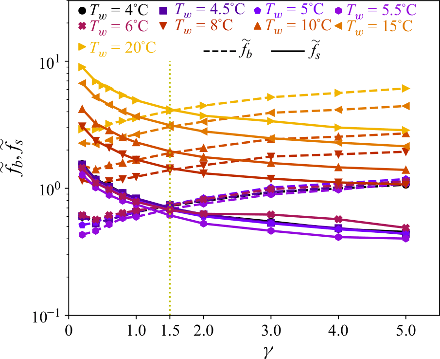
4. Effect of ambient temperature for fixed Rayleigh number
$\boldsymbol{Ra} \boldsymbol{=} \boldsymbol{1.46} \boldsymbol{\times} \boldsymbol{10}^{\boldsymbol{5}}$

In the preceding section, we systematically examined the influence of aspect ratio on the side, basal and overall melting with the ambient temperature maintained at $T_{w}=20^{\,\circ }\mathrm{C}$
. However, the density of water exhibits a non-monotonic dependence on temperature, as described by (2.4). This density anomaly of water near
$T_{w}=20^{\,\circ }\mathrm{C}$
. However, the density of water exhibits a non-monotonic dependence on temperature, as described by (2.4). This density anomaly of water near $4^{\,\circ }\textrm {C}$
can give rise to distinct flow regimes and morphological evolutions for varying ambient temperatures (Wang et al. Reference Wang, Calzavarini, Sun and Toschi2021a
,
Reference Wang, Jiang, Du, Sun and Calzavarinib
; Weady et al. Reference Weady, Tong, Zidovska and Ristroph2022). Consequently, in this section, we investigate the impact of the ambient temperature while keeping the Rayleigh number fixed at
$4^{\,\circ }\textrm {C}$
can give rise to distinct flow regimes and morphological evolutions for varying ambient temperatures (Wang et al. Reference Wang, Calzavarini, Sun and Toschi2021a
,
Reference Wang, Jiang, Du, Sun and Calzavarinib
; Weady et al. Reference Weady, Tong, Zidovska and Ristroph2022). Consequently, in this section, we investigate the impact of the ambient temperature while keeping the Rayleigh number fixed at ${Ra}=1.46\times 10^{5}$
.
${Ra}=1.46\times 10^{5}$
.
The normalised side mean melt rate $\widetilde {f}_{s}$
and the normalised basal mean melt rate
$\widetilde {f}_{s}$
and the normalised basal mean melt rate $\widetilde {f}_{b}$
as a function of the aspect ratio
$\widetilde {f}_{b}$
as a function of the aspect ratio $\gamma$
for different ambient temperatures are presented in figure 7. The symbols connected by solid lines represent the normalised side mean melt rate
$\gamma$
for different ambient temperatures are presented in figure 7. The symbols connected by solid lines represent the normalised side mean melt rate $\widetilde {f}_{s}$
, and the symbols connected by dashed lines indicate the normalised basal mean melt rate
$\widetilde {f}_{s}$
, and the symbols connected by dashed lines indicate the normalised basal mean melt rate $\widetilde {f}_{b}$
. As the aspect ratio
$\widetilde {f}_{b}$
. As the aspect ratio $\gamma$
increases, the side mean melt rate
$\gamma$
increases, the side mean melt rate $\widetilde {f}_{s}$
decreases, while the basal mean melt rate
$\widetilde {f}_{s}$
decreases, while the basal mean melt rate $\widetilde {f}_{b}$
increases. Notably,
$\widetilde {f}_{b}$
increases. Notably, $\widetilde {f}_{s}$
and
$\widetilde {f}_{s}$
and $\widetilde {f}_{b}$
attain similar values at
$\widetilde {f}_{b}$
attain similar values at $\gamma \approx 1.5$
. For
$\gamma \approx 1.5$
. For $\gamma \leqslant 1$
,
$\gamma \leqslant 1$
, $\widetilde {f}_{s}$
is larger than
$\widetilde {f}_{s}$
is larger than $\widetilde {f}_{b}$
, indicating a side-melting dominant regime. However, for
$\widetilde {f}_{b}$
, indicating a side-melting dominant regime. However, for $\gamma \geqslant 2$
,
$\gamma \geqslant 2$
, $\widetilde {f}_{b}$
is larger than
$\widetilde {f}_{b}$
is larger than $\widetilde {f}_{s}$
, suggesting a basal-melting dominant regime. These observations are consistent with those for various Rayleigh numbers depicted in figure 2.
$\widetilde {f}_{s}$
, suggesting a basal-melting dominant regime. These observations are consistent with those for various Rayleigh numbers depicted in figure 2.
(a) The normalised side mean melt rate $\widetilde {f}_{s}$
as a function of the Stefan number
$\widetilde {f}_{s}$
as a function of the Stefan number ${St}$
and the ambient temperature
${St}$
and the ambient temperature $T_{w}$
in the side-melting dominant regime (
$T_{w}$
in the side-melting dominant regime ( $\gamma \leqslant 1$
). (b) The normalised basal mean melt rate
$\gamma \leqslant 1$
). (b) The normalised basal mean melt rate $\widetilde {f}_{b}$
as a function of the Stefan number
$\widetilde {f}_{b}$
as a function of the Stefan number ${St}$
and the ambient temperature
${St}$
and the ambient temperature $T_{w}$
in the basal-melting dominant regime (
$T_{w}$
in the basal-melting dominant regime ( $\gamma \geqslant 2$
).
$\gamma \geqslant 2$
).
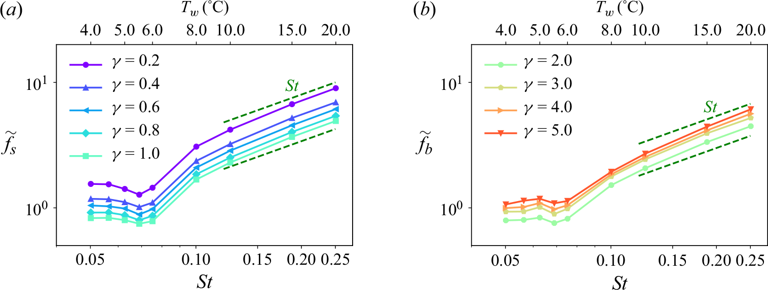
The normalised side mean melt rate $\widetilde {f}_{s}$
and the normalised basal mean melt rate
$\widetilde {f}_{s}$
and the normalised basal mean melt rate $\widetilde {f}_{b}$
as a function of the Stefan number
$\widetilde {f}_{b}$
as a function of the Stefan number ${St}$
and the ambient temperature
${St}$
and the ambient temperature $T_{w}$
are shown in figure 8. When the ambient temperature is
$T_{w}$
are shown in figure 8. When the ambient temperature is $T_{w}\geqslant 15^{\,\circ }\textrm {C}$
,
$T_{w}\geqslant 15^{\,\circ }\textrm {C}$
, $\widetilde {f}_{s}$
and
$\widetilde {f}_{s}$
and $\widetilde {f}_{b}$
follow the
$\widetilde {f}_{b}$
follow the ${St}$
scaling relation as indicated by (3.2). However, as the ambient temperature
${St}$
scaling relation as indicated by (3.2). However, as the ambient temperature $T_{w}$
decreases, the influence of the density anomaly intensifies, causing
$T_{w}$
decreases, the influence of the density anomaly intensifies, causing $\widetilde {f}_{s}$
and
$\widetilde {f}_{s}$
and $\widetilde {f}_{b}$
to deviate from the
$\widetilde {f}_{b}$
to deviate from the ${St}$
scaling relation. Notably, for
${St}$
scaling relation. Notably, for $T_{w}\leqslant 8^{\,\circ }\textrm {C}$
,
$T_{w}\leqslant 8^{\,\circ }\textrm {C}$
, $\widetilde {f}_{s}$
and
$\widetilde {f}_{s}$
and $\widetilde {f}_{b}$
exhibit a non-monotonic dependence on the ambient temperature
$\widetilde {f}_{b}$
exhibit a non-monotonic dependence on the ambient temperature $T_{w}$
: as the ambient temperature
$T_{w}$
: as the ambient temperature $T_{w}$
decreases,
$T_{w}$
decreases, $\widetilde {f}_{s}$
and
$\widetilde {f}_{s}$
and $\widetilde {f}_{b}$
initially decrease, reaching minimum values at
$\widetilde {f}_{b}$
initially decrease, reaching minimum values at $T_{w}\approx 5.5^{\,\circ }\textrm {C}$
, and then slightly increase to larger values at
$T_{w}\approx 5.5^{\,\circ }\textrm {C}$
, and then slightly increase to larger values at $T_{w}\approx 4^{\,\circ }\textrm {C}$
.
$T_{w}\approx 4^{\,\circ }\textrm {C}$
.
The instantaneous temperature field at time $t/t_{m}=0.1$
for the ice block with aspect ratio
$t/t_{m}=0.1$
for the ice block with aspect ratio $\gamma =1.0$
for ambient temperature (a)
$\gamma =1.0$
for ambient temperature (a) $T_{w} =4^{\,\circ }\textrm {C}$
, (b)
$T_{w} =4^{\,\circ }\textrm {C}$
, (b) $T_{w} =5^{\,\circ }\textrm {C}$
and (c)
$T_{w} =5^{\,\circ }\textrm {C}$
and (c) $T_{w} =10^{\,\circ }\textrm {C}$
at
$T_{w} =10^{\,\circ }\textrm {C}$
at ${Ra}=1.46\times 10^{5}$
. Here,
${Ra}=1.46\times 10^{5}$
. Here, $\widetilde {T}=T/T_{w}$
. The dimensionless instantaneous heat fluxes
$\widetilde {T}=T/T_{w}$
. The dimensionless instantaneous heat fluxes $ {Nu}$
around the ice surface are 0.84, 0.63 and 0.84 in (a), (b) and (c), respectively.
$ {Nu}$
around the ice surface are 0.84, 0.63 and 0.84 in (a), (b) and (c), respectively.
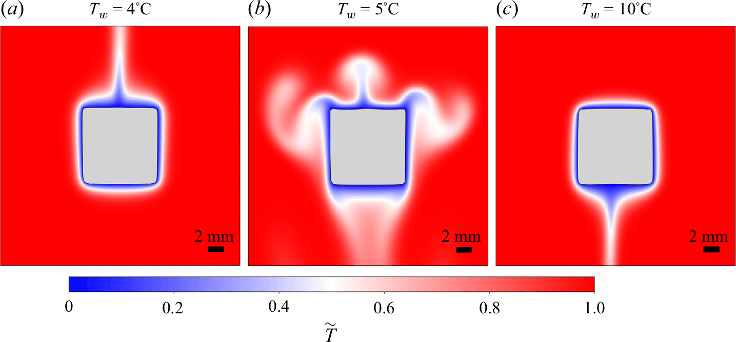
The non-monotonic behaviours of $\widetilde {f}_{s}$
and
$\widetilde {f}_{s}$
and $\widetilde {f}_{b}$
arise from the density anomaly effect, which results in distinct flow structures at different ambient temperatures. Figure 9 shows the instantaneous temperature field for the ice block with aspect ratio
$\widetilde {f}_{b}$
arise from the density anomaly effect, which results in distinct flow structures at different ambient temperatures. Figure 9 shows the instantaneous temperature field for the ice block with aspect ratio $\gamma =1.0$
for three different ambient temperatures at
$\gamma =1.0$
for three different ambient temperatures at ${Ra}=1.46\times 10^{5}$
. At low ambient temperatures (figure 9
a), the meltwater ascends due to its density at
${Ra}=1.46\times 10^{5}$
. At low ambient temperatures (figure 9
a), the meltwater ascends due to its density at $0^{\,\circ }\textrm {C}$
being lower than that of the surrounding water. Conversely, at high ambient temperatures (figure 9
c), the meltwater descends as its density exceeds that of the surrounding water. At intermediate ambient temperatures (figure 9
b), a bi-directional flow pattern emerges: the meltwater initially moves upwards; as it mixes with and is warmed by the surrounding water, its density increases and becomes larger than that of the surrounding water, causing it to move downwards. This bi-directional flow pattern envelops the ice block, inhibiting the ambient warm water from directly contacting the ice, which results in a reduced dimensionless instantaneous heat flux
$0^{\,\circ }\textrm {C}$
being lower than that of the surrounding water. Conversely, at high ambient temperatures (figure 9
c), the meltwater descends as its density exceeds that of the surrounding water. At intermediate ambient temperatures (figure 9
b), a bi-directional flow pattern emerges: the meltwater initially moves upwards; as it mixes with and is warmed by the surrounding water, its density increases and becomes larger than that of the surrounding water, causing it to move downwards. This bi-directional flow pattern envelops the ice block, inhibiting the ambient warm water from directly contacting the ice, which results in a reduced dimensionless instantaneous heat flux $ {Nu}$
around the ice surface, and consequently slows down the melt rate. A similar bi-directional flow pattern was observed during the melting of an ice cylinder in
$ {Nu}$
around the ice surface, and consequently slows down the melt rate. A similar bi-directional flow pattern was observed during the melting of an ice cylinder in $5.6^{\,\circ }\mathrm{C}$
fresh water (Weady et al. Reference Weady, Tong, Zidovska and Ristroph2022) and the melting of an ellipsoid in
$5.6^{\,\circ }\mathrm{C}$
fresh water (Weady et al. Reference Weady, Tong, Zidovska and Ristroph2022) and the melting of an ellipsoid in $5.25^{\,\circ }\mathrm{C}$
fresh water (Yang et al. Reference Yang, van den Ham, Verzicco, Lohse and Huisman2024a
).
$5.25^{\,\circ }\mathrm{C}$
fresh water (Yang et al. Reference Yang, van den Ham, Verzicco, Lohse and Huisman2024a
).
(a) The normalised side mean melt rate $\widetilde {f}_{s}$
as a function of the aspect ratio
$\widetilde {f}_{s}$
as a function of the aspect ratio $\gamma$
for different ambient temperatures
$\gamma$
for different ambient temperatures $T_{w}$
. (b) The normalised basal mean melt rate
$T_{w}$
. (b) The normalised basal mean melt rate $\widetilde {f}_{b}$
as a function of the aspect ratio
$\widetilde {f}_{b}$
as a function of the aspect ratio $\gamma$
for different ambient temperatures
$\gamma$
for different ambient temperatures $T_{w}$
.
$T_{w}$
.
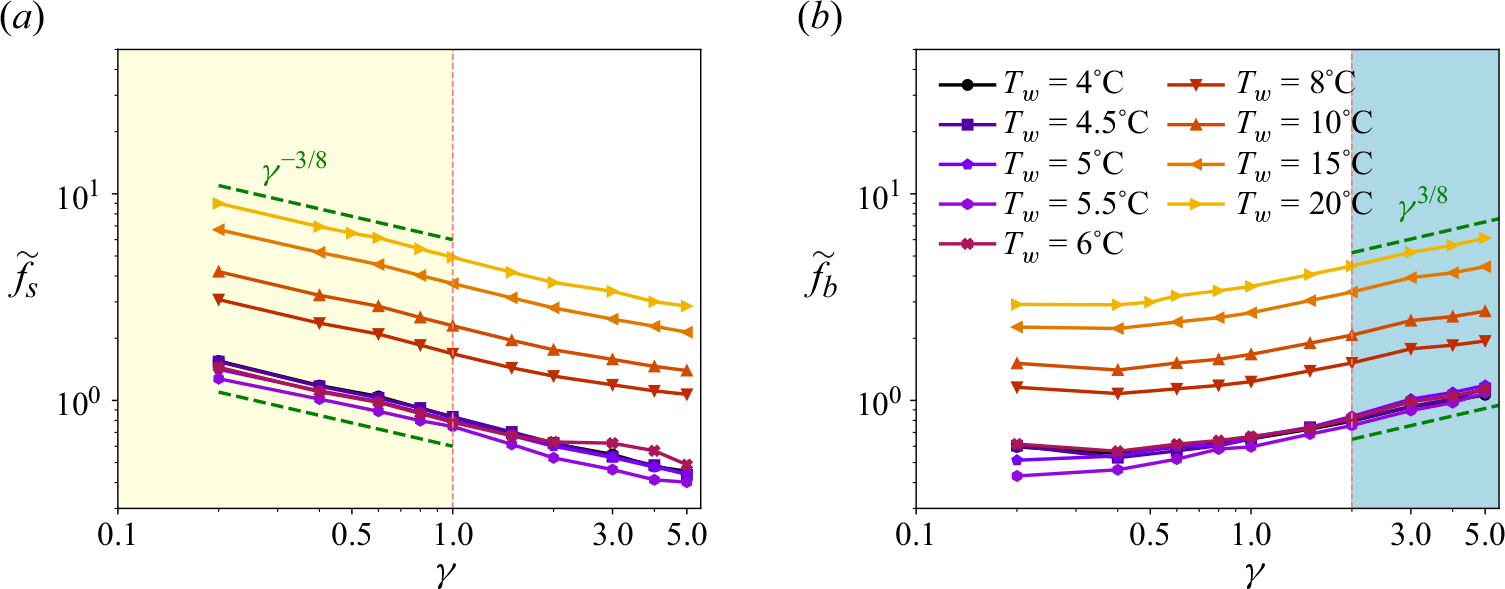
The normalised side mean melt rate $\widetilde {f}_{s}$
and the normalised basal mean melt rate
$\widetilde {f}_{s}$
and the normalised basal mean melt rate $\widetilde {f}_{b}$
as a function of the aspect ratio
$\widetilde {f}_{b}$
as a function of the aspect ratio $\gamma$
for different ambient temperatures
$\gamma$
for different ambient temperatures $T_{w}$
are illustrated in figure 10. It is observed that for various ambient temperatures, the side mean melt rate
$T_{w}$
are illustrated in figure 10. It is observed that for various ambient temperatures, the side mean melt rate $\widetilde {f}_{s}$
adheres to the
$\widetilde {f}_{s}$
adheres to the $\gamma ^{-3/8}$
scaling relation in the side-melting dominant regime (
$\gamma ^{-3/8}$
scaling relation in the side-melting dominant regime ( $\gamma \leqslant 1$
), consistent with the scaling relation in (3.3). Similarly, the basal mean melt rate
$\gamma \leqslant 1$
), consistent with the scaling relation in (3.3). Similarly, the basal mean melt rate $\widetilde {f}_{b}$
follows the
$\widetilde {f}_{b}$
follows the $\gamma ^{3/8}$
scaling relation in the basal-melting dominant regime (
$\gamma ^{3/8}$
scaling relation in the basal-melting dominant regime ( $\gamma \geqslant 2$
), which is consistent with the scaling relation in (3.4).
$\gamma \geqslant 2$
), which is consistent with the scaling relation in (3.4).
The compensated normalised overall mean melt rate $\widetilde {f}/ {St}$
as a function of
$\widetilde {f}/ {St}$
as a function of $\gamma$
for different ambient temperatures. The symbols represent the compensated normalised overall mean melt rates
$\gamma$
for different ambient temperatures. The symbols represent the compensated normalised overall mean melt rates $\widetilde {f}/ {St}$
, while six green dashed lines represent the theoretical predictions from (3.12) for the overall mean melt rates
$\widetilde {f}/ {St}$
, while six green dashed lines represent the theoretical predictions from (3.12) for the overall mean melt rates $\widetilde {f}/ {St}$
at
$\widetilde {f}/ {St}$
at $T_{w}=4.5^{\,\circ }\textrm {C}$
,
$T_{w}=4.5^{\,\circ }\textrm {C}$
, $5^{\,\circ }\textrm {C}$
,
$5^{\,\circ }\textrm {C}$
, $6^{\,\circ }\textrm {C}$
,
$6^{\,\circ }\textrm {C}$
, $8^{\,\circ }\textrm {C}$
,
$8^{\,\circ }\textrm {C}$
, $10^{\,\circ }\textrm {C}$
and
$10^{\,\circ }\textrm {C}$
and $15^{\,\circ }\textrm {C}$
, respectively.
$15^{\,\circ }\textrm {C}$
, respectively.

The compensated normalised overall mean melt rate $\widetilde {f}/ {St}$
as function of
$\widetilde {f}/ {St}$
as function of $\gamma$
for different ambient temperatures is shown in figure 11. The compensated normalised overall mean melt rate
$\gamma$
for different ambient temperatures is shown in figure 11. The compensated normalised overall mean melt rate $\widetilde {f}/ {St}$
at
$\widetilde {f}/ {St}$
at $T_{w}=20^{\,\circ }\textrm {C}$
almost collapses with that at
$T_{w}=20^{\,\circ }\textrm {C}$
almost collapses with that at $T_{w}=15^{\,\circ }\textrm {C}$
, indicating that
$T_{w}=15^{\,\circ }\textrm {C}$
, indicating that $\widetilde {f}$
follows the
$\widetilde {f}$
follows the ${St}$
scaling relation at
${St}$
scaling relation at $T_{w}\geqslant 15^{\,\circ }\textrm {C}$
. However, as the ambient temperature
$T_{w}\geqslant 15^{\,\circ }\textrm {C}$
. However, as the ambient temperature $T_{w}$
decreases, the density anomaly effect becomes stronger, and
$T_{w}$
decreases, the density anomaly effect becomes stronger, and $\widetilde {f}$
no longer adheres to the
$\widetilde {f}$
no longer adheres to the ${St}$
scaling relation. Moreover, the overall mean melt rate
${St}$
scaling relation. Moreover, the overall mean melt rate $\widetilde {f}$
exhibits a non-monotonic dependence on the ambient temperature
$\widetilde {f}$
exhibits a non-monotonic dependence on the ambient temperature $T_{w}$
: as the ambient temperature
$T_{w}$
: as the ambient temperature $T_{w}$
decreases, the overall mean melt rate
$T_{w}$
decreases, the overall mean melt rate $\widetilde {f}$
initially decreases and then increases. These results are consistent with the behaviours of
$\widetilde {f}$
initially decreases and then increases. These results are consistent with the behaviours of $\widetilde {f}_{s}$
and
$\widetilde {f}_{s}$
and $\widetilde {f}_{b}$
for different ambient temperatures.
$\widetilde {f}_{b}$
for different ambient temperatures.
Furthermore, the normalised overall mean melt rate $\widetilde {f}$
for different ambient temperatures also exhibits a non-monotonic dependence on
$\widetilde {f}$
for different ambient temperatures also exhibits a non-monotonic dependence on $\gamma$
: as
$\gamma$
: as $\gamma$
increases,
$\gamma$
increases, $\widetilde {f}$
initially decreases and then increases. This non-monotonic behaviour is attributed to the competition between side and basal melting, similar to the observations for the overall mean melt rate
$\widetilde {f}$
initially decreases and then increases. This non-monotonic behaviour is attributed to the competition between side and basal melting, similar to the observations for the overall mean melt rate $\widetilde {f}$
for different Rayleigh numbers (figure 6). It is observed that the minimum overall mean melt rate occurs at aspect ratio
$\widetilde {f}$
for different Rayleigh numbers (figure 6). It is observed that the minimum overall mean melt rate occurs at aspect ratio $\gamma _{{min}}\approx 2$
for both high ambient temperatures (
$\gamma _{{min}}\approx 2$
for both high ambient temperatures ( $T_{w}\gt 6^{\,\circ }\textrm {C}$
) and low ambient temperatures (
$T_{w}\gt 6^{\,\circ }\textrm {C}$
) and low ambient temperatures ( $T_{w}\lt 5^{\,\circ }\textrm {C}$
), corresponding to regimes of downward and upward flow, respectively. However, for intermediate temperatures (
$T_{w}\lt 5^{\,\circ }\textrm {C}$
), corresponding to regimes of downward and upward flow, respectively. However, for intermediate temperatures ( $5^{\,\circ }\textrm {C}\leqslant T_{w}\leqslant 6^{\,\circ }\textrm {C}$
),
$5^{\,\circ }\textrm {C}\leqslant T_{w}\leqslant 6^{\,\circ }\textrm {C}$
), $\gamma _{{min}}$
decreases to approximately 1.5. This phenomenon can be explained as follows. For intermediate temperatures, a bi-directional flow pattern emerges, characterised by both upward and downward flows. This bi-directional flow surrounds the ice block, insulating it from direct contact with the ambient warm water. Consequently, convection around the ice block weakens, and the influence of the perimeter length of the ice block becomes more significant. Therefore, for intermediate temperatures,
$\gamma _{{min}}$
decreases to approximately 1.5. This phenomenon can be explained as follows. For intermediate temperatures, a bi-directional flow pattern emerges, characterised by both upward and downward flows. This bi-directional flow surrounds the ice block, insulating it from direct contact with the ambient warm water. Consequently, convection around the ice block weakens, and the influence of the perimeter length of the ice block becomes more significant. Therefore, for intermediate temperatures, $\gamma _{{min}}$
shifts towards a value near
$\gamma _{{min}}$
shifts towards a value near $\gamma =1$
, where the perimeter of the square-shaped ice block is minimal.
$\gamma =1$
, where the perimeter of the square-shaped ice block is minimal.
The behaviours predicted by the theoretical model in (3.12) are also illustrated in figure 11. Six green dashed lines represent the theoretical predictions from (3.12) for the overall mean melt rates $\widetilde {f}/ {St}$
at
$\widetilde {f}/ {St}$
at $T_{w}=4.5^{\,\circ }\textrm {C}$
,
$T_{w}=4.5^{\,\circ }\textrm {C}$
, $5^{\,\circ }\textrm {C}$
,
$5^{\,\circ }\textrm {C}$
, $6^{\,\circ }\textrm {C}$
,
$6^{\,\circ }\textrm {C}$
, $8^{\,\circ }\textrm {C}$
,
$8^{\,\circ }\textrm {C}$
, $10^{\,\circ }\textrm {C}$
and
$10^{\,\circ }\textrm {C}$
and $15^{\,\circ }\textrm {C}$
, respectively. The theoretical model in (3.12) captures the non-monotonic behaviour of
$15^{\,\circ }\textrm {C}$
, respectively. The theoretical model in (3.12) captures the non-monotonic behaviour of $\widetilde {f}$
as function of
$\widetilde {f}$
as function of $\gamma$
, and accurately estimates the mean melt rate
$\gamma$
, and accurately estimates the mean melt rate $\widetilde {f}$
across various ambient temperatures, particularly in the side-melting dominant regime (
$\widetilde {f}$
across various ambient temperatures, particularly in the side-melting dominant regime ( $\gamma \leqslant 1$
) and the basal-melting dominant regime (
$\gamma \leqslant 1$
) and the basal-melting dominant regime ( $\gamma \geqslant 2$
). This demonstrates that the theoretical model in (3.12) is also applicable for estimating the overall mean melt rate for different ambient temperatures.
$\gamma \geqslant 2$
). This demonstrates that the theoretical model in (3.12) is also applicable for estimating the overall mean melt rate for different ambient temperatures.
It is noted that the influence of ambient temperature is examined only at relatively low Rayleigh numbers. This restriction arises because at low ambient temperatures, the melt rates are significantly slower, often several times lower than those observed at ambient temperature $20^{\,\circ }\textrm {C}$
. Additionally, the time step required for simulating low-temperature cases is much smaller than that for
$20^{\,\circ }\textrm {C}$
. Additionally, the time step required for simulating low-temperature cases is much smaller than that for $20^{\,\circ }\textrm {C}$
, resulting in a substantially higher computational cost, particularly at high Rayleigh numbers. As a result, the effect of ambient temperature at higher Rayleigh numbers is not considered in the present study and is left for future investigation. Nevertheless, it can be anticipated that cavity formation persists at sufficiently high Rayleigh numbers, although the critical Rayleigh number for cavity formation at low ambient temperatures is expected to differ from that at
$20^{\,\circ }\textrm {C}$
, resulting in a substantially higher computational cost, particularly at high Rayleigh numbers. As a result, the effect of ambient temperature at higher Rayleigh numbers is not considered in the present study and is left for future investigation. Nevertheless, it can be anticipated that cavity formation persists at sufficiently high Rayleigh numbers, although the critical Rayleigh number for cavity formation at low ambient temperatures is expected to differ from that at $20^{\,\circ }\textrm {C}$
. Furthermore, when the ambient temperature is very low (below
$20^{\,\circ }\textrm {C}$
. Furthermore, when the ambient temperature is very low (below $5^{\,\circ }\textrm {C}$
), the density anomaly of water induces upward motion of the meltwater, leading to the cavity formation at the top surface of the ice block.
$5^{\,\circ }\textrm {C}$
), the density anomaly of water induces upward motion of the meltwater, leading to the cavity formation at the top surface of the ice block.
5. Conclusions and outlook
In this study, we have investigated the effect of the aspect ratio of an ice block with fixed volume (or area) on the side, basal and overall mean melt rates across a range of Rayleigh numbers and ambient temperatures through direct numerical simulations. Theoretical scaling relations and a model are proposed to estimate the side, basal and overall mean melt rates. They can describe the simulation results over the considered range of Rayleigh numbers and ambient temperatures.
The aspect ratio of the ice block has a significant effect on the relative contributions of side and basal melting. Specifically, the side mean melt rate $\widetilde {f}_{s}$
is larger than the basal mean melt rate
$\widetilde {f}_{s}$
is larger than the basal mean melt rate $\widetilde {f}_{b}$
for aspect ratio
$\widetilde {f}_{b}$
for aspect ratio $\gamma \leqslant 1$
, while
$\gamma \leqslant 1$
, while $\widetilde {f}_{b}$
exceeds
$\widetilde {f}_{b}$
exceeds $\widetilde {f}_{s}$
for
$\widetilde {f}_{s}$
for $\gamma \geqslant 2$
.
$\gamma \geqslant 2$
.
The influence of the Rayleigh number is first investigated for fixed ambient temperature $T_{w}=20^{\,\circ }\mathrm{C}$
. The side mean melt rate
$T_{w}=20^{\,\circ }\mathrm{C}$
. The side mean melt rate $\widetilde {f}_{s}$
is found to follow a
$\widetilde {f}_{s}$
is found to follow a ${Ra}^{1/4}\gamma ^{-3/8}$
scaling relation in the side-melting dominant regime (
${Ra}^{1/4}\gamma ^{-3/8}$
scaling relation in the side-melting dominant regime ( $\gamma \leqslant 1$
) across different Rayleigh numbers. In contrast, the basal mean melt rate
$\gamma \leqslant 1$
) across different Rayleigh numbers. In contrast, the basal mean melt rate $\widetilde {f}_{b}$
exhibits a more complex behaviour: in the basal-melting dominant regime (
$\widetilde {f}_{b}$
exhibits a more complex behaviour: in the basal-melting dominant regime ( $\gamma \geqslant 2$
),
$\gamma \geqslant 2$
), $\widetilde {f}_{b}$
adheres to a
$\widetilde {f}_{b}$
adheres to a ${Ra}^{1/4}\gamma ^{3/8}$
scaling relation at low Rayleigh numbers (
${Ra}^{1/4}\gamma ^{3/8}$
scaling relation at low Rayleigh numbers ( ${Ra}\leqslant 10^{6}$
), but transitions to a
${Ra}\leqslant 10^{6}$
), but transitions to a ${Ra}^{1/3}\gamma ^{1/2}$
scaling relation at high Rayleigh numbers (
${Ra}^{1/3}\gamma ^{1/2}$
scaling relation at high Rayleigh numbers ( ${Ra} \gt 10^{6}$
). This scaling transition is attributed to the formation of a bottom cavity caused by flow separation at high Rayleigh numbers, which enhances local mixing and subsequently increases the local melt rate. Furthermore, the overall mean melt rate
${Ra} \gt 10^{6}$
). This scaling transition is attributed to the formation of a bottom cavity caused by flow separation at high Rayleigh numbers, which enhances local mixing and subsequently increases the local melt rate. Furthermore, the overall mean melt rate $\widetilde {f}$
displays a non-monotonic dependence on the aspect ratio
$\widetilde {f}$
displays a non-monotonic dependence on the aspect ratio $\gamma$
, initially decreasing and then increasing as
$\gamma$
, initially decreasing and then increasing as $\gamma$
increases. This non-monotonic behaviour arises from the competition between side and basal melting. Based on the scaling relations for the side and basal mean melt rates, a theoretical model is proposed to also estimate the overall mean melt rate
$\gamma$
increases. This non-monotonic behaviour arises from the competition between side and basal melting. Based on the scaling relations for the side and basal mean melt rates, a theoretical model is proposed to also estimate the overall mean melt rate $\widetilde {f}$
. The proposed theoretical model successfully captures the non-monotonic behaviour of
$\widetilde {f}$
. The proposed theoretical model successfully captures the non-monotonic behaviour of $\widetilde {f}$
, and also provides accurate predictions of
$\widetilde {f}$
, and also provides accurate predictions of $\widetilde {f}$
, especially in the regimes dominated by side melting (
$\widetilde {f}$
, especially in the regimes dominated by side melting ( $\gamma \leqslant 0.8$
) and basal melting (
$\gamma \leqslant 0.8$
) and basal melting ( $\gamma \geqslant 3$
).
$\gamma \geqslant 3$
).
Furthermore, the effect of ambient temperature is examined for fixed Rayleigh number ${Ra}=1.46\times 10^{5}$
. The side, basal and overall mean melt rates follow the
${Ra}=1.46\times 10^{5}$
. The side, basal and overall mean melt rates follow the ${St}$
scaling relation for the ambient temperature
${St}$
scaling relation for the ambient temperature $T_{w}\geqslant 15^{\,\circ }\textrm {C}$
. However, as the ambient temperature decreases further, the side, basal and overall mean melt rates deviate from the
$T_{w}\geqslant 15^{\,\circ }\textrm {C}$
. However, as the ambient temperature decreases further, the side, basal and overall mean melt rates deviate from the ${St}$
scaling relation and exhibit a non-monotonic dependence on the ambient temperature, which is attributed to the density anomaly effect. Additionally, the proposed theoretical scaling relations and model are found to accurately predict the side, basal and overall mean melt rates for the analysed different ambient temperatures.
${St}$
scaling relation and exhibit a non-monotonic dependence on the ambient temperature, which is attributed to the density anomaly effect. Additionally, the proposed theoretical scaling relations and model are found to accurately predict the side, basal and overall mean melt rates for the analysed different ambient temperatures.
In summary, our findings provide insight into the role of the aspect ratio on side and basal melting of ice in freshwater. The proposed theoretical scaling relations and model may offer improved predictions of melt rates for ice blocks or icebergs with varying aspect ratios, and serve as a useful framework for refining large-scale geophysical models. It is, however, important to note that the Rayleigh number range considered in this study is considerably lower than that observed at geophysical scales. The applicability of the proposed scaling relations for the side and basal melt rates to geophysical scales remains to be verified. Nonetheless, the methodology for estimating the overall melt rate based on the side and basal melt rates can be extended to geophysical icebergs. In future studies, it would be worthwhile to further explore additional factors such as the influence of salinity, mean shear from the ambient flow, and spatial variations in the temperature along the ice surface.
Movies depicting the instantaneous fields corresponding to the cases presented in figures 5 and 9 are provided in the supplementary material. The solver is available at https://github.com/chowland/AFiD-MuRPhFi. Mean statistics for the cases in the present study are available at https://doi.org/10.5281/zenodo.14589263.
Supplementary movies.
Supplementary movies are available at https://doi.org/10.1017/jfm.2025.302.
Funding.
This work was financially supported by the European Union (ERC, MultiMelt, 101094492). We also acknowledge the EuroHPC Joint Undertaking for awarding the project EHPC-REG-2023R03-178 access to the EuroHPC supercomputer Discoverer, hosted by Sofia Tech Park (Bulgaria).
Declaration of interests.
The authors report no conflict of interest.
Appendix A. The influence of the computational domain size and the grid convergence test of the simulations
The influence of the computational domain size is analysed for the 2-D case with ${Ra} = 1.82 \times 10^{4}$
,
${Ra} = 1.82 \times 10^{4}$
, $\gamma = 1.0$
and
$\gamma = 1.0$
and ${St} = 0.25$
, as shown in figure 12(a). The normalised overall mean melt rate
${St} = 0.25$
, as shown in figure 12(a). The normalised overall mean melt rate $\widetilde {f}$
exhibits convergence as the ratio
$\widetilde {f}$
exhibits convergence as the ratio $L/D$
of the box size
$L/D$
of the box size $L$
to the effective length
$L$
to the effective length $D$
of the ice block increases, which indicates that the impact of the side walls on
$D$
of the ice block increases, which indicates that the impact of the side walls on $\widetilde {f}$
becomes negligible when
$\widetilde {f}$
becomes negligible when $L/D \geqslant 8$
. Based on this observation, the domain size is selected as
$L/D \geqslant 8$
. Based on this observation, the domain size is selected as $L/D = 10$
for the present study.
$L/D = 10$
for the present study.
Grid convergence tests were conducted for multiple cases to ensure convergent results. For brevity, we present only the grid-independence test for the 2-D case with ${Ra}=1.82\times 10^{4}$
,
${Ra}=1.82\times 10^{4}$
, $\gamma =1.0$
and
$\gamma =1.0$
and ${St}=0.25$
in figure 12(b–d). The results exhibit convergence with increasing grid resolution. Consequently, we selected
${St}=0.25$
in figure 12(b–d). The results exhibit convergence with increasing grid resolution. Consequently, we selected $N=320$
as the grid resolution for our simulations, as indicated by the black circle in figure 12(c).
$N=320$
as the grid resolution for our simulations, as indicated by the black circle in figure 12(c).
(a) The normalised overall mean melt rate $\widetilde {f}$
as a function of the ratio
$\widetilde {f}$
as a function of the ratio $L/D$
of the box size
$L/D$
of the box size $L$
to the effective length
$L$
to the effective length $D$
of the ice block for the 2-D case with
$D$
of the ice block for the 2-D case with ${Ra}=1.82\times 10^{4}$
,
${Ra}=1.82\times 10^{4}$
, $\gamma =1.0$
and
$\gamma =1.0$
and ${St}=0.25$
. The domain size is chosen as
${St}=0.25$
. The domain size is chosen as $L/D = 10$
, as indicated by the black circle. (b) The normalised area of ice
$L/D = 10$
, as indicated by the black circle. (b) The normalised area of ice $A(t)/A_{0}$
as a function of time
$A(t)/A_{0}$
as a function of time $t/t_{d}$
for the 2-D case with
$t/t_{d}$
for the 2-D case with ${Ra}=1.82\times 10^{4}$
,
${Ra}=1.82\times 10^{4}$
, $\gamma =1.0$
and
$\gamma =1.0$
and ${St}=0.25$
. Here,
${St}=0.25$
. Here, $A_{0}$
is the initial area of the ice block. (c) The normalised overall mean melt rate
$A_{0}$
is the initial area of the ice block. (c) The normalised overall mean melt rate $\widetilde {f}$
as a function of the grid resolution
$\widetilde {f}$
as a function of the grid resolution $N$
for the velocity and temperature fields. Convergence is observed with increasing
$N$
for the velocity and temperature fields. Convergence is observed with increasing $N$
, and the resolution
$N$
, and the resolution $N = 320$
was selected, as denoted by the black circle. (d) The relative error
$N = 320$
was selected, as denoted by the black circle. (d) The relative error $ \operatorname {Er}=|t_{m}-t_{m_{0}} |/t_{m_{0}}$
as a function of the grid spacing
$ \operatorname {Er}=|t_{m}-t_{m_{0}} |/t_{m_{0}}$
as a function of the grid spacing $\Delta x$
, where
$\Delta x$
, where $t_{m_{0}}$
is the melt time
$t_{m_{0}}$
is the melt time $t_{m}$
for the highest resolution. The selected grid resolution is highlighted by the black circle.
$t_{m}$
for the highest resolution. The selected grid resolution is highlighted by the black circle.
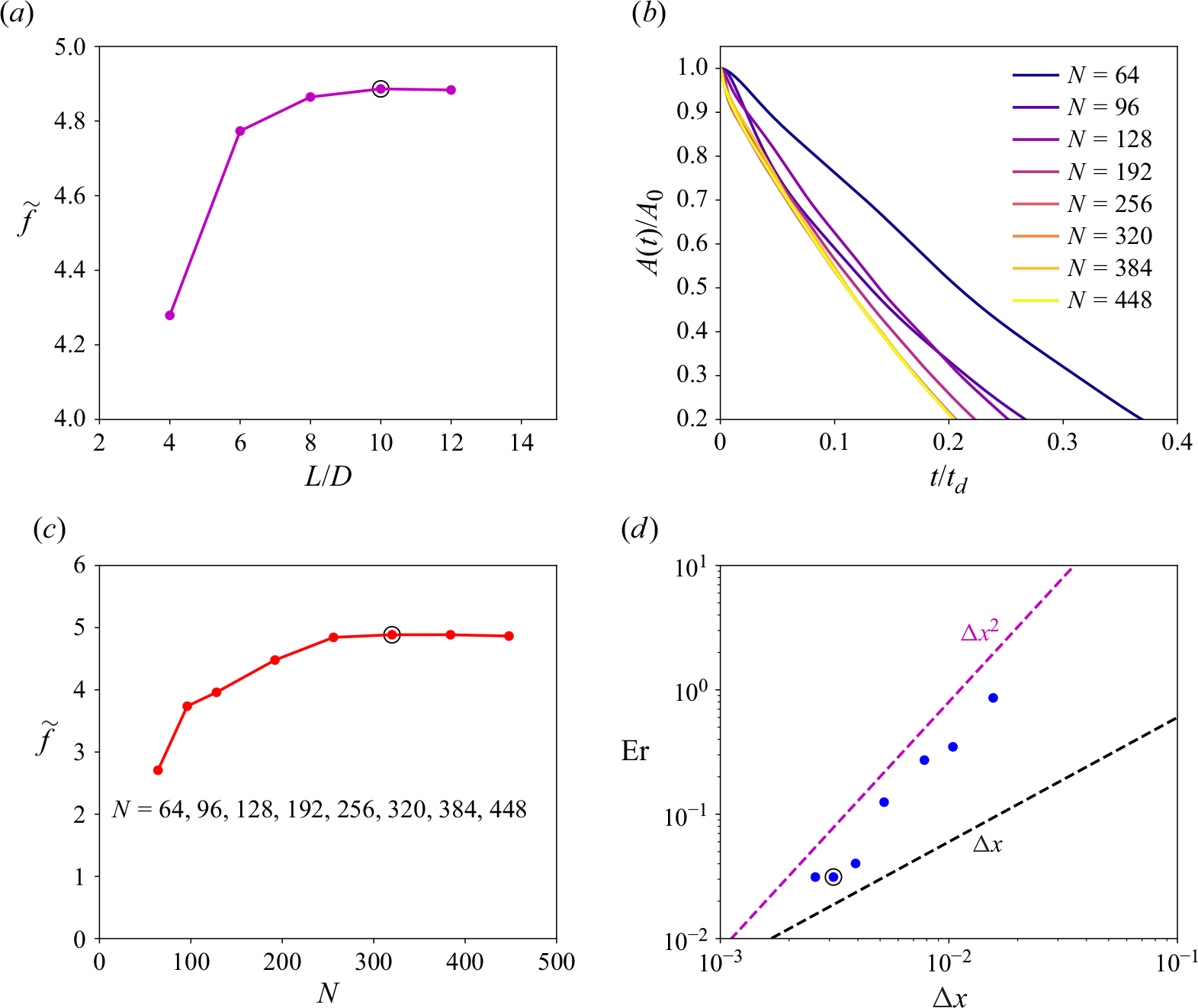
Appendix B. The temporal evolutions of the equivalent aspect ratio and the side and basal melt rates
The temporal evolutions of the equivalent aspect ratio $\gamma ( t )$
as well as the side and basal melt rates
$\gamma ( t )$
as well as the side and basal melt rates $\widetilde {f}_{s}(t)$
and
$\widetilde {f}_{s}(t)$
and $\widetilde {f}_{b}(t)$
for various initial aspect ratios
$\widetilde {f}_{b}(t)$
for various initial aspect ratios $\gamma$
at
$\gamma$
at ${Ra}=1.17\times 10^{6}$
are presented in figure 13. Additionally, figure 14 illustrates the evolutions of the normalised instantaneous side and basal melt rates,
${Ra}=1.17\times 10^{6}$
are presented in figure 13. Additionally, figure 14 illustrates the evolutions of the normalised instantaneous side and basal melt rates, $\widetilde {f}_{s}(t)/\gamma ^{-3/8}$
and
$\widetilde {f}_{s}(t)/\gamma ^{-3/8}$
and $\widetilde {f}_{b}(t)/\gamma ^{3/8}$
, as functions of the normalised instantaneous equivalent aspect ratio
$\widetilde {f}_{b}(t)/\gamma ^{3/8}$
, as functions of the normalised instantaneous equivalent aspect ratio $\gamma (t)/\gamma$
at the same Rayleigh number. Similar trends are observed for cases with different Rayleigh numbers and ambient temperatures, and are omitted here for brevity.
$\gamma (t)/\gamma$
at the same Rayleigh number. Similar trends are observed for cases with different Rayleigh numbers and ambient temperatures, and are omitted here for brevity.
(a) The temporal evolution of the instantaneous equivalent aspect ratio $\gamma ( t )$
for various initial aspect ratios
$\gamma ( t )$
for various initial aspect ratios $\gamma$
at
$\gamma$
at ${Ra}=1.17\times 10^{6}$
, where
${Ra}=1.17\times 10^{6}$
, where $\gamma ( t )=w ( t )/h ( t )$
. (b) The temporal evolution of the instantaneous side melt rate
$\gamma ( t )=w ( t )/h ( t )$
. (b) The temporal evolution of the instantaneous side melt rate $\widetilde {f}_{s}(t)$
for various initial aspect ratios
$\widetilde {f}_{s}(t)$
for various initial aspect ratios $\gamma \leqslant 1$
at
$\gamma \leqslant 1$
at ${Ra}=1.17\times 10^{6}$
. (c) The temporal evolution of the instantaneous basal melt rate
${Ra}=1.17\times 10^{6}$
. (c) The temporal evolution of the instantaneous basal melt rate $\widetilde {f}_{b}(t)$
for various initial aspect ratios
$\widetilde {f}_{b}(t)$
for various initial aspect ratios $\gamma \geqslant 1$
at
$\gamma \geqslant 1$
at ${Ra}=1.17\times 10^{6}$
. Here,
${Ra}=1.17\times 10^{6}$
. Here, $t_{m}$
denotes the time required to melt
$t_{m}$
denotes the time required to melt $V_{m}=80\,\%$
of the initial area in 2-D simulations, and
$V_{m}=80\,\%$
of the initial area in 2-D simulations, and $t/t_{m}=1.0$
represents the time at which
$t/t_{m}=1.0$
represents the time at which $80\,\%$
of the initial area has melted. Furthermore, the black filled circle, red square and blue star correspond to the times required to melt
$80\,\%$
of the initial area has melted. Furthermore, the black filled circle, red square and blue star correspond to the times required to melt $50\,\%$
,
$50\,\%$
, $60\,\%$
and
$60\,\%$
and $70\,\%$
of the initial area, respectively, as shown in (b) and (c).
$70\,\%$
of the initial area, respectively, as shown in (b) and (c).
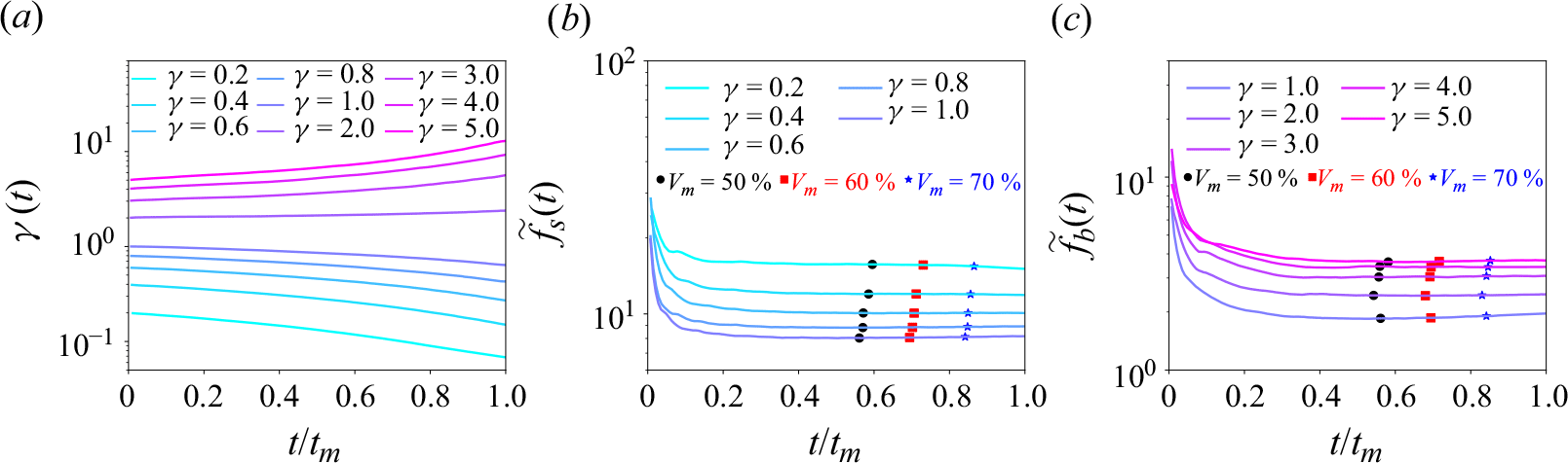
(a) The temporal evolution of the normalised instantaneous side melt rate $\widetilde {f}_{s}(t)/\gamma ^{-3/8}$
for various initial aspect ratios
$\widetilde {f}_{s}(t)/\gamma ^{-3/8}$
for various initial aspect ratios $\gamma \leqslant 1$
as a function of the normalised instantaneous equivalent aspect ratio
$\gamma \leqslant 1$
as a function of the normalised instantaneous equivalent aspect ratio $\gamma ( t )/\gamma$
at
$\gamma ( t )/\gamma$
at ${Ra}=1.17\times 10^{6}$
. (b) The temporal evolution of the normalised instantaneous basal melt rate
${Ra}=1.17\times 10^{6}$
. (b) The temporal evolution of the normalised instantaneous basal melt rate $\widetilde {f}_{b}(t)/\gamma ^{3/8}$
for various initial aspect ratios
$\widetilde {f}_{b}(t)/\gamma ^{3/8}$
for various initial aspect ratios $\gamma \geqslant 2$
as a function of the normalised instantaneous equivalent aspect ratio
$\gamma \geqslant 2$
as a function of the normalised instantaneous equivalent aspect ratio $\gamma ( t )/\gamma$
at
$\gamma ( t )/\gamma$
at ${Ra}=1.17\times 10^{6}$
. In both plots, the vertical dashed lines indicate the values of
${Ra}=1.17\times 10^{6}$
. In both plots, the vertical dashed lines indicate the values of $\gamma ( t )/\gamma$
at the melt time
$\gamma ( t )/\gamma$
at the melt time $t_{m}$
.
$t_{m}$
.
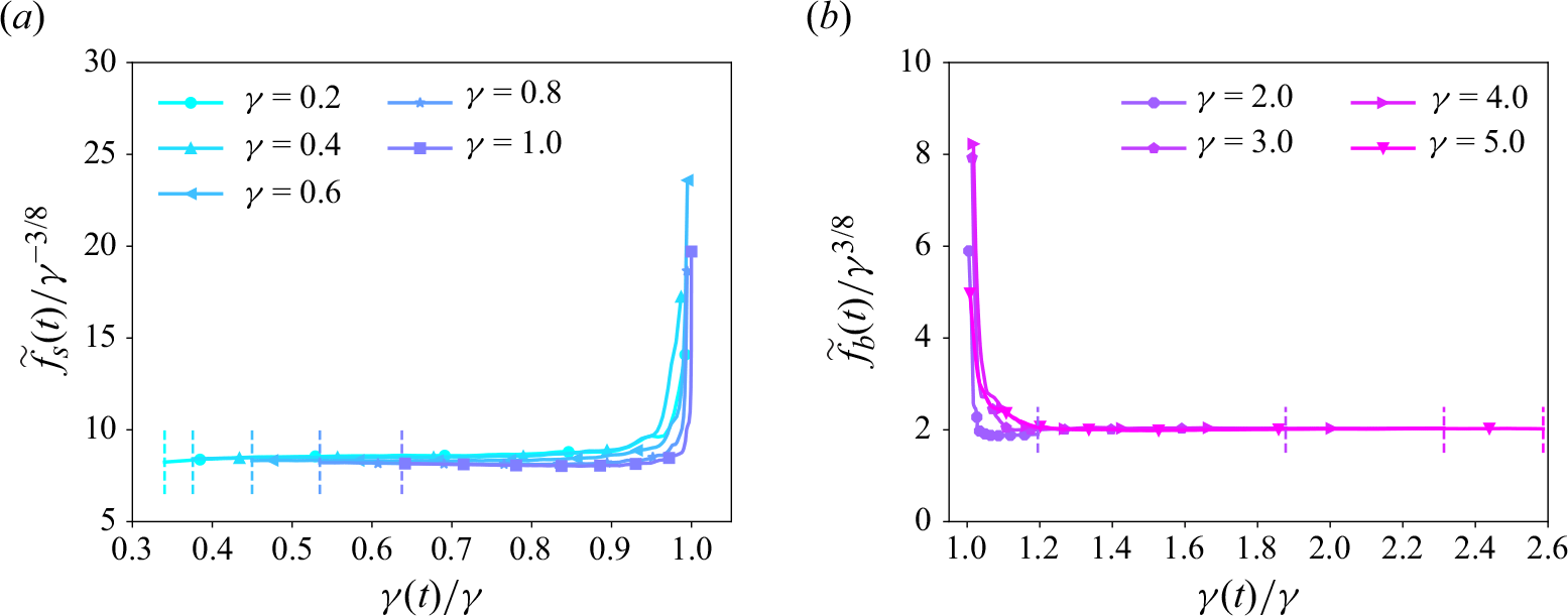
As shown in figure 13(a), the equivalent aspect ratio $\gamma ( t )$
is changing over time, with a gradual decrease for initial aspect ratio
$\gamma ( t )$
is changing over time, with a gradual decrease for initial aspect ratio $\gamma \leqslant 1$
, and a gradual increase for
$\gamma \leqslant 1$
, and a gradual increase for $\gamma \geqslant 2$
. This phenomenon can be attributed to the relative magnitudes of the side and basal mean melt rates. For the cases with initial aspect ratio
$\gamma \geqslant 2$
. This phenomenon can be attributed to the relative magnitudes of the side and basal mean melt rates. For the cases with initial aspect ratio $\gamma \leqslant 1$
, figure 2 demonstrates that the side mean melt rate
$\gamma \leqslant 1$
, figure 2 demonstrates that the side mean melt rate $\widetilde {f}_{s}$
exceeds the basal mean melt rate
$\widetilde {f}_{s}$
exceeds the basal mean melt rate $\widetilde {f}_{b}$
, leading to a progressive reduction in
$\widetilde {f}_{b}$
, leading to a progressive reduction in $\gamma ( t )$
as the ice melts. Furthermore, figure 14(a) indicates that the range of the normalised instantaneous equivalent aspect ratio
$\gamma ( t )$
as the ice melts. Furthermore, figure 14(a) indicates that the range of the normalised instantaneous equivalent aspect ratio $\gamma ( t )/\gamma$
increases as the initial aspect ratio
$\gamma ( t )/\gamma$
increases as the initial aspect ratio $\gamma$
decreases. This can be explained by the trend observed in figure 2, where the difference between
$\gamma$
decreases. This can be explained by the trend observed in figure 2, where the difference between $\widetilde {f}_{s}$
and
$\widetilde {f}_{s}$
and $\widetilde {f}_{b}$
becomes more pronounced as
$\widetilde {f}_{b}$
becomes more pronounced as $\gamma$
decreases.
$\gamma$
decreases.
Conversely, for cases with $\gamma \geqslant 2$
, figure 2 reveals that the basal mean melt rate
$\gamma \geqslant 2$
, figure 2 reveals that the basal mean melt rate $\widetilde {f}_{b}$
is larger than the side mean melt rate
$\widetilde {f}_{b}$
is larger than the side mean melt rate $\widetilde {f}_{s}$
, resulting in a gradual increase in
$\widetilde {f}_{s}$
, resulting in a gradual increase in $\gamma ( t )$
. Moreover, figure 14(b) shows that the range of
$\gamma ( t )$
. Moreover, figure 14(b) shows that the range of $\gamma ( t )/\gamma$
increases as
$\gamma ( t )/\gamma$
increases as $\gamma$
increases, which can be attributed to the increasing disparity between
$\gamma$
increases, which can be attributed to the increasing disparity between $\widetilde {f}_{b}$
and
$\widetilde {f}_{b}$
and $\widetilde {f}_{s}$
as
$\widetilde {f}_{s}$
as $\gamma$
increases, as depicted in figure 2.
$\gamma$
increases, as depicted in figure 2.
The temporal evolutions of the side and basal melt rates $\widetilde {f}_{s}(t)$
and
$\widetilde {f}_{s}(t)$
and $\widetilde {f}_{b}(t)$
exhibit similar trends. Initially, both melt rates are relatively large due to the higher temperature gradients near the ice surface. Then the side and basal melt rates
$\widetilde {f}_{b}(t)$
exhibit similar trends. Initially, both melt rates are relatively large due to the higher temperature gradients near the ice surface. Then the side and basal melt rates $\widetilde {f}_{s}(t)$
and
$\widetilde {f}_{s}(t)$
and $\widetilde {f}_{b}(t)$
gradually decrease, reaching nearly constant values as the ice continues to melt. Both
$\widetilde {f}_{b}(t)$
gradually decrease, reaching nearly constant values as the ice continues to melt. Both $\widetilde {f}_{s}(t)$
and
$\widetilde {f}_{s}(t)$
and $\widetilde {f}_{b}(t)$
are almost constant over time, particularly within the range
$\widetilde {f}_{b}(t)$
are almost constant over time, particularly within the range $60\,\%\leqslant V_{m} \leqslant 80\,\%$
. It is noted that the influence of the initial condition becomes less significant as the final melt fraction
$60\,\%\leqslant V_{m} \leqslant 80\,\%$
. It is noted that the influence of the initial condition becomes less significant as the final melt fraction $V_{m}$
increases. Consequently, a larger value of
$V_{m}$
increases. Consequently, a larger value of $V_{m}$
is preferable to effectively mitigate the effect of the initial condition. However, the final melt fraction
$V_{m}$
is preferable to effectively mitigate the effect of the initial condition. However, the final melt fraction $V_{m}$
cannot be excessively large, as the ice block may fracture into two pieces when
$V_{m}$
cannot be excessively large, as the ice block may fracture into two pieces when $V_{m} \approx 90\,\%$
, particularly under high Rayleigh number and large aspect ratio conditions. Thus a final melt fraction
$V_{m} \approx 90\,\%$
, particularly under high Rayleigh number and large aspect ratio conditions. Thus a final melt fraction $V_{m}=80\,\%$
is chosen in the present study to significantly reduce the impact of the initial condition.
$V_{m}=80\,\%$
is chosen in the present study to significantly reduce the impact of the initial condition.
Figure 14 demonstrates that the normalised instantaneous side melt rate $\widetilde {f}_{s}(t)/\gamma ^{-3/8}$
for initial aspect ratios
$\widetilde {f}_{s}(t)/\gamma ^{-3/8}$
for initial aspect ratios $\gamma \leqslant 1$
and the normalised instantaneous basal melt rate
$\gamma \leqslant 1$
and the normalised instantaneous basal melt rate $\widetilde {f}_{b}(t)/\gamma ^{3/8}$
for initial aspect ratios
$\widetilde {f}_{b}(t)/\gamma ^{3/8}$
for initial aspect ratios $\gamma \geqslant 2$
nearly collapse respectively, particularly within the range
$\gamma \geqslant 2$
nearly collapse respectively, particularly within the range $60\,\%\leqslant V_{m} \leqslant 80\,\%$
. This suggests that despite the temporal evolution of the equivalent aspect ratio
$60\,\%\leqslant V_{m} \leqslant 80\,\%$
. This suggests that despite the temporal evolution of the equivalent aspect ratio $\gamma (t)$
deviating from its initial value
$\gamma (t)$
deviating from its initial value $\gamma$
, the proposed scaling relations in the present study remain valid for the instantaneous side melt rate
$\gamma$
, the proposed scaling relations in the present study remain valid for the instantaneous side melt rate $\widetilde {f}_{s}(t)$
in the side-melting dominant regime (
$\widetilde {f}_{s}(t)$
in the side-melting dominant regime ( $\gamma \leqslant 1$
), and for the instantaneous basal melt rate
$\gamma \leqslant 1$
), and for the instantaneous basal melt rate $\widetilde {f}_{b}(t)$
in the basal-melting dominant regime (
$\widetilde {f}_{b}(t)$
in the basal-melting dominant regime ( $\gamma \geqslant 2$
).
$\gamma \geqslant 2$
).
However, it is important to note that the variation in the instantaneous equivalent aspect ratio $\gamma (t)$
is relatively large, particularly for cases with small or large initial aspect ratios. The substantial departure of
$\gamma (t)$
is relatively large, particularly for cases with small or large initial aspect ratios. The substantial departure of $\gamma (t)$
from its initial value
$\gamma (t)$
from its initial value $\gamma$
results in the breakdown of the proposed scaling relations for predicting the side melt rate
$\gamma$
results in the breakdown of the proposed scaling relations for predicting the side melt rate $\widetilde {f}_{s}$
in the basal-melting dominant regime (
$\widetilde {f}_{s}$
in the basal-melting dominant regime ( $\gamma \geqslant 2$
), and the basal melt rate
$\gamma \geqslant 2$
), and the basal melt rate $\widetilde {f}_{b}$
in the side-melting dominant regime (
$\widetilde {f}_{b}$
in the side-melting dominant regime ( $\gamma \leqslant 1$
), as illustrated in figures 3(c) and 4(c). Consequently, these discrepancies also impact the accuracy of estimating the overall mean melt rate
$\gamma \leqslant 1$
), as illustrated in figures 3(c) and 4(c). Consequently, these discrepancies also impact the accuracy of estimating the overall mean melt rate $\widetilde {f}$
using the proposed scaling relations for
$\widetilde {f}$
using the proposed scaling relations for $\widetilde {f}_{s}$
and
$\widetilde {f}_{s}$
and $\widetilde {f}_{b}$
.
$\widetilde {f}_{b}$
.
To improve the predictive capability of the scaling relations for $\widetilde {f}_{s}$
in the basal-melting dominant regime,
$\widetilde {f}_{s}$
in the basal-melting dominant regime, $\widetilde {f}_{b}$
in the side-melting dominant regime, and the overall mean melt rate
$\widetilde {f}_{b}$
in the side-melting dominant regime, and the overall mean melt rate $\widetilde {f}$
, future studies should account for the temporal evolution of the equivalent aspect ratio.
$\widetilde {f}$
, future studies should account for the temporal evolution of the equivalent aspect ratio.


 Open access