





Introduction
In modern wireless communication systems, low-pass filters (LPFs) with features such as sharp roll-off (RO), low insertion loss, high return loss, wide stopband, and high rejection levels are essential for selecting desired signals and suppressing harmonic and spurious interferences [Reference Hong and Lancaster1]. Among various implementations, microstrip-based LPFs have gained widespread adoption due to their compact size, low cost, ease of fabrication, and excellent compatibility with planar integration technology. These advantages make them particularly well-suited for high-frequency and compact system applications. However, conventional microstrip LPF designs are often constrained by relatively slow cutoff transitions and limited stopband bandwidth, which restrict their performance in scenarios demanding high selectivity and wide out-of-band suppression [Reference Pozar2].
To address this problem, several LPFs with sharp RO and wide stopband have been reported. For instance, in [Reference Hayati, Akbari and Salahi4], a split-ring resonator loaded with folded polygonal patches is employed to design an LPF with a wide stopband and very sharp RO. A compact LPF utilizing multiple transmission zeros for stopband extension is reported in [Reference Chen, Run-Shuo and Chu5]. The LPF in [Reference Kumar and Parihar6] employs three coupled stepped-impedance resonators, achieving a ROR of 440 dB/GHz and a spurious-free bandwidth up to 16 GHz with 15 dB attenuation. In [Reference Hayati, Zarghami and Shama7], series main resonators with meandered lines are used to improve ROR, while two coupled radial stubs are introduced to broaden the stopband. To obtain steep RO with compact size, bent high-impedance microstrip lines are used to realize an elliptic LPF in [Reference Hoseinabadi, Tavakoli, Fatemi, Jalal and Setoudeh8]. In [Reference Hayati, Salahi, Akbari, Zargari and Abbott9], a simple-structure LPF achieves a 123 dB/GHz transition rate using open stubs, and in [Reference Roshani, Yahya, Khazaei, Roshani and Karami10], a windmill-shaped resonator is introduced to sharpen the transition. Both [Reference Hayati, Salahi, Akbari, Zargari and Abbott9] and [Reference Roshani, Yahya, Khazaei, Roshani and Karami10] enhance the stopband performance by incorporating suppression elements specifically designed to generate transmission zeros. However, most existing studies focus primarily on the locations of transmission zeros introduced by these suppression structures, with limited attention paid to the behavior of the stopband bandwidth around fixed transmission zero locations.
In this letter, a microstrip LPF with sharp RO and excellent near- and far-stopband suppression is proposed. The design integrates a stepped-impedance hairpin-type resonator (SIHTR) and a pair of asymmetric T-shaped resonators (TSRs). The SIHTR defines the 3 dB cutoff frequency and provides sharp RO. To further enhance the out-of-band suppression performance, the TSR is modeled and analyzed using an equivalent circuit approach. Based on this analysis, a stopband bandwidth control method is proposed, which relies on impedance tuning. By adjusting a key impedance parameter defined within the equivalent circuit, effective control of the stopband bandwidth is achieved without altering the positions of the out-of-band transmission zeros (TZs). Specifically, the proposed TSRs achieve narrow stopband at low frequencies and wide stopband at high frequencies, enhancing near- and far-stopband suppression, respectively.
Design of the proposed resonator
Design of SIHR
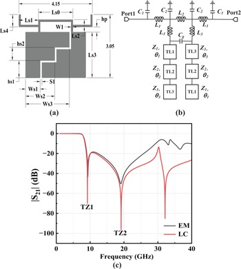
Based on the hairpin structure proposed in[Reference Hasegawa, Yasuzumi, Uwano and Hashimoto3], the original low-impedance coupled lines are replaced with a pair of mirror-symmetric stepped-impedance coupled lines, thereby enhancing the selectivity of the low-pass response. Figure 1(a) illustrates the physical layout of the SIHTR. The corresponding LC equivalent circuit model of the SIHTR (Fig. 1(b)) consists of the following components: transmission lines TL1  $\sim$ TL3 with characteristic impedances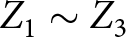 $Z_{1} \sim Z_{3}$ and electrical lengths $\theta_{1}$ $\sim$ $\theta_{3}$; a coupling capacitor $C_{g}$ between the stepped-impedance transmission lines; grounding parasitic capacitors $C_{1}$ and $C_{2}$ associated with the high-impedance lines; and inductors $L_{1}$ $\sim$ $L_{3}$. The values of the circuit components, extracted through curve fitting based on full-wave simulation results, are listed in Table 1.
(a) Layout of SIHTR (W1=0.1, Ls0=1.95, Ls1=1, Ls2=0.6, Ls3=2.2, Ls4=0.6, hp=0.25, S1=0.1, Ws1=0.825, Ws2=1.65, Ws3=2.475, hs1=0.83, hs2=0.63 (unit: mm)). (b) LC equivalent circuit of SIHTR. (c) LC and EM simulation results.

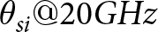

As illustrated in Fig. 1(c), the simulated frequency response from the LC equivalent circuit exhibits excellent agreement with the full-wave electromagnetic (EM) simulation results, thereby validating the accuracy of the proposed circuit model. The simulated response indicates that the SIHTR achieves a 3 dB cut-off frequency at 8 GHz. In addition, two distinct transmission zeros (TZs) are observed at 9.21 GHz (TZ1) and 19.16 GHz (TZ2), respectively, which contribute to enhanced out-of-band rejection and improved filter selectivity.
Design of TSRs
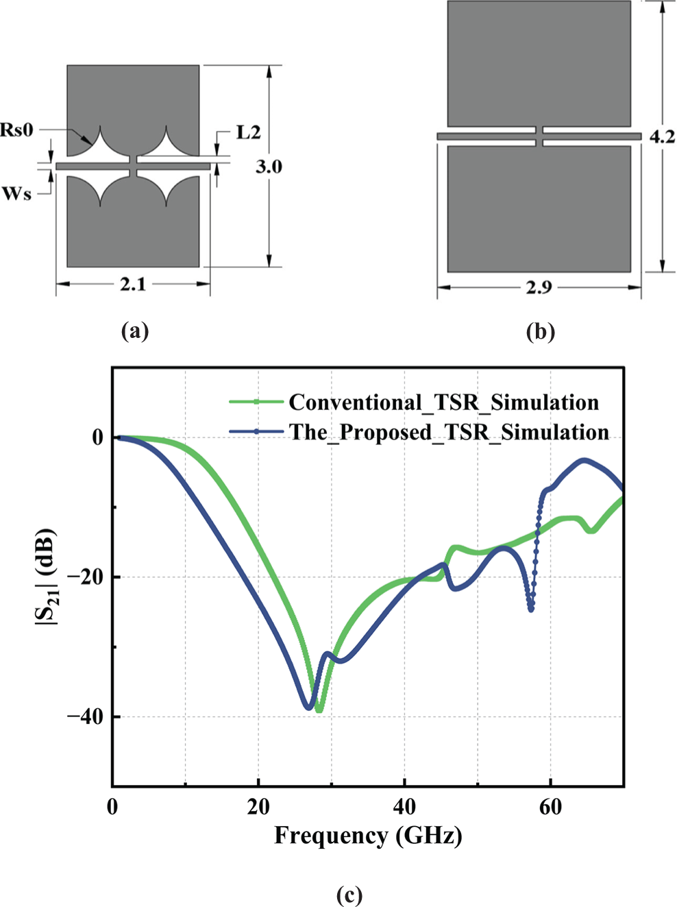
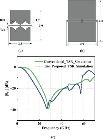
To realize the LPF with an extended stopband, a modified TSR is proposed as the suppression cell, whose structure is shown in Fig. 2(a). For comparison, the conventional TSR structure is depicted in Fig. 2(b). The simulated responses of both (Fig. 2(c)) demonstrate that the proposed TSR achieves a significant performance enhancement, primarily characterized by a much wider stopband. Furthermore, the proposed TSR also affords a substantial reduction in layout area, occupying only approximately half that of its conventional counterpart. These results confirm the proposed TSR’s dual advantages in both performance and compactness.
(a) Layout of the proposed TSR (unit: mm). (b) Layout of conventional TSR (unit: mm). (c)  $|S_{21}|$ simulation comparison.
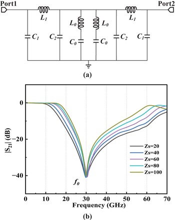
The LC equivalent circuit of the proposed TSR is shown in Fig. 3(a). The inductors  $L_{0}$ and $L_{1}$, together with the parasitic ground capacitors $C_{1}$ and $C_{2}$, model the high-impedance transmission lines, while $C_{0}$ represents the capacitance of the open stubs.
(a) LC equivalent circuit of the proposed TSR. (b) Simulated results of the proposed TSR versus different Zs.

Based on the LC equivalent circuit shown in Fig. 3(a), the resonant frequency  $f_0$ (corresponding angular frequency $\omega_{0}$) of the series resonator composed of the inductor $L_0$ and the capacitor $C_0$ is defined as:
 \begin{equation}
f_{0}=\frac{1}{2\pi\sqrt{L_{0}C_{0}}}
\end{equation}
\begin{equation}
f_{0}=\frac{1}{2\pi\sqrt{L_{0}C_{0}}}
\end{equation} \begin{equation}
\omega_{0}=2\pi f_{0}
\end{equation}
\begin{equation}
\omega_{0}=2\pi f_{0}
\end{equation}Define an impedance:
 \begin{equation}
Zs=\sqrt{\frac{L_{0}}{C_{0}}}
\end{equation}
\begin{equation}
Zs=\sqrt{\frac{L_{0}}{C_{0}}}
\end{equation}Then, the ABCD matrix of the TSR is expressed as:
 \begin{equation}\begin{bmatrix}A&B\\C&D\end{bmatrix}_{total}=\begin{bmatrix}A&B\\C&D\end{bmatrix}_{\pi_1}\cdot\begin{bmatrix}A&B\\C&D\end{bmatrix}_R\cdot\begin{bmatrix}A&B\\C&D\end{bmatrix}_{\pi_2}\end{equation}
Owing to the conversion relationship between S-parameters and ABCD parameters[Reference Pozar2]:
 \begin{equation}
S_{21}=\frac{2}{A+B/Z_{0}+CZ_{0}+D}
\end{equation}
\begin{equation}
S_{21}=\frac{2}{A+B/Z_{0}+CZ_{0}+D}
\end{equation} Where  $Z_{0}$ denotes the characteristic impedance at the TSR input/output ports. According to formula (4):
 \begin{equation}|S_{21}|=\frac{1}{\sqrt{|A_1|^{2}+|A_2+A_3|^{2}}}
\end{equation}
\begin{equation}|S_{21}|=\frac{1}{\sqrt{|A_1|^{2}+|A_2+A_3|^{2}}}
\end{equation} \begin{equation}
\begin{aligned}
A_1 &=(1-\omega^2 L_{1}C_{1})(1-\omega^2 L_{1}C_{2})-\omega L_{1}\left[\vphantom{\frac{2\omega \omega_{0}(1-\omega^2 L_{1}C_{1})}{(\omega_{0}^2-\omega^2)Zs}}\omega(C_{1}+\right.\\
&\quad \left.C_{2})-\omega^3 L_{1}C_{1}C_{2}+\frac{2\omega \omega_{0}(1-\omega^2 L_{1}C_{1})}{(\omega_{0}^2-\omega^2)Zs}\right]
\end{aligned}
\end{equation}
\begin{equation}
\begin{aligned}
A_1 &=(1-\omega^2 L_{1}C_{1})(1-\omega^2 L_{1}C_{2})-\omega L_{1}\left[\vphantom{\frac{2\omega \omega_{0}(1-\omega^2 L_{1}C_{1})}{(\omega_{0}^2-\omega^2)Zs}}\omega(C_{1}+\right.\\
&\quad \left.C_{2})-\omega^3 L_{1}C_{1}C_{2}+\frac{2\omega \omega_{0}(1-\omega^2 L_{1}C_{1})}{(\omega_{0}^2-\omega^2)Zs}\right]
\end{aligned}
\end{equation} \begin{equation}
A_{2}=\frac{\omega L_{1}}{Z_{0}}\left[(1-\omega^2 L_{1}C_{2})-\frac{\omega^2 \omega_{0}L_{1}}{(\omega_{0}^2-\omega^2)Zs}\right]
\end{equation}
\begin{equation}
A_{2}=\frac{\omega L_{1}}{Z_{0}}\left[(1-\omega^2 L_{1}C_{2})-\frac{\omega^2 \omega_{0}L_{1}}{(\omega_{0}^2-\omega^2)Zs}\right]
\end{equation} \begin{equation}
\begin{aligned}
A_{3} &=Z_{0}(1-\omega^2 L_{1}C_{1})\left[\vphantom{\frac{2\omega \omega_{0}(1-\omega^2 L_{1}C_{1})}{(\omega_{0}^2-\omega^2)Zs}}\omega(C_{1}+C_{2})-\omega^3 L_{1}C_{1}C_{2}\right.\\
&\quad \left.+\frac{2\omega \omega_{0}(1-\omega^2 L_{1}C_{1})}{(\omega_{0}^2-\omega^2)Zs}\right]
\end{aligned}
\end{equation}
\begin{equation}
\begin{aligned}
A_{3} &=Z_{0}(1-\omega^2 L_{1}C_{1})\left[\vphantom{\frac{2\omega \omega_{0}(1-\omega^2 L_{1}C_{1})}{(\omega_{0}^2-\omega^2)Zs}}\omega(C_{1}+C_{2})-\omega^3 L_{1}C_{1}C_{2}\right.\\
&\quad \left.+\frac{2\omega \omega_{0}(1-\omega^2 L_{1}C_{1})}{(\omega_{0}^2-\omega^2)Zs}\right]
\end{aligned}
\end{equation} As shown in formulas (6) $\sim$(9), increasing Zs raises $|S_{21}|$ near the resonant frequency $f_0$, indicating weaker suppression and a narrower stopband. Based on this, the inductance $L_{0}$ in the TSR’s LC model is calculated using formulas (1) and (3). Subsequently, the length variable $L_{2}$ (Ws=0.1mm) is estimated using the formula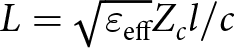 $L=\sqrt{\varepsilon_\mathrm{eff}}Z_cl/c$, where $Z_c$, $l$,
$l$,  $c$, and $\varepsilon_{eff}$ are the characteristic impedance, line length, speed of light, and effective dielectric constant, respectively. To ensure that the TSR achieves the desired resonant frequency $f_0$, the radius Rs0 was optimized accordingly. Figure 3(b) presents simulation results under different Zs values, confirming that larger Zs leads to reduced stopband bandwidth, consistent with theoretical predictions. Moreover, a higher Zs sharpens the transition from passband to stopband on the lower-frequency side of $f_0$, enhancing near-end out-of-band suppression.
Based on the above properties, two TSRs with distinct resonant frequencies are designed. TSR1, resonating at 15.25 GHz with a narrow stopband, improves near-stopband suppression, while TSR2, with a 30 GHz resonance and wide stopband, enhances far-stopband suppression. To reduce layout size, TSR1’s high-impedance line is folded. The optimized layouts and simulation results of TSR1 and TSR2 are shown in Fig. 4(a)–4(c).
(a) Layout of TSR1 (W1=0.1, Lt1=0.55, Lt2=0.45, Lt3=2Rs1=0.7, Lt4=0.2 (unit: mm)). (b) Layout of TSR2 (W2=0.1, Lt5=1.1, Lt6=3Rs2=1.12, Lt7=0.2 (unit: mm)). (c) Simulated results of TSR1. (d) Simulated results of TSR2.

Design of the proposed LPF
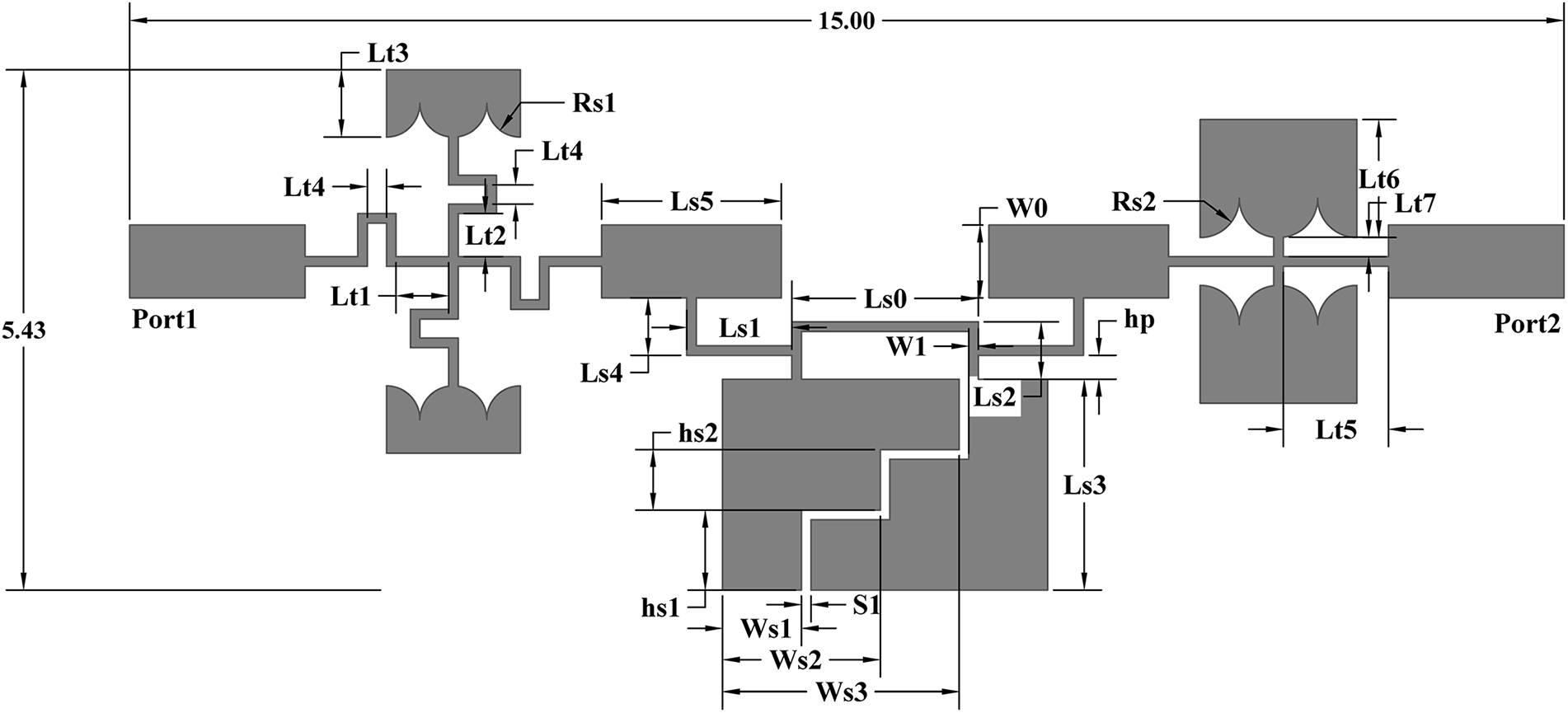
By integrating the SIHTR with TSR1 and TSR2, the final LPF layout is shown in Fig. 5, where two interconnect structures (ICSs) are introduced to connect the SIHTR and TSRs. In addition to providing electrical connectivity, these ICSs also serve as effective tuning elements for performance optimization. As shown in Fig. 6(a), adjusting the length of ICS section Ls5 effectively suppresses out-of-band spurious resonances. Modifying radius Rs1, as depicted in (Fig. 6(b)), enhances suppression in the near-end out-of-band region. Meanwhile, tuning Rs2 (Fig. 6(c)) improves the in-band  $|S_{11}|$ flatness and further strengthens near-stopband suppression. Figure 6(d) demonstrates that increasing width Ws2 results in a lower 3 dB cutoff frequency, with Ws1, Ws2, and Ws3 varying proportionally as Ws3 = 1.5Ws2 = 3Ws1.
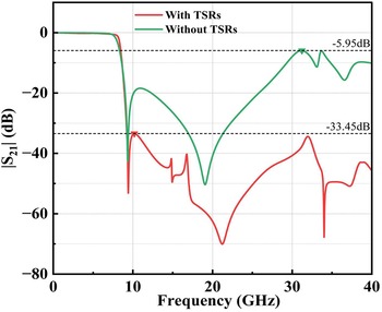
The key structural parameters of the filter are obtained through optimization using the full-wave electromagnetic simulation software HFSS. Figure 7 compares the frequency responses of the LPF with and without the incorporation of TSRs. The results demonstrate that the inclusion of TSRs not only achieves a wider stopband and deeper attenuation but also significantly enhances the out-of-band interference rejection capability of the filter.
Layout of the proposed LPF (W0=0.76, W1=0.1, Ls0=1.95, Ls1=1, Ls2=0.6, Ls3=2.2, Ls4=0.6, Ls5=2.08, hp=0.25, S1=0.1, Ws1=0.825, Ws2=1.65, Ws3=2.475, hs1=0.83, hs2=0.63, Lt1=0.55, Lt2=0.45, Lt3=0.7,Lt4=0.2, Lt5=1.1, Lt6=1.23, Lt7=0.2, Rs1=0.35, and Rs2=0.41 (unit: mm)).

(a) Simulated results of the proposed LPF versus different Ls5. (b) Simulated results of the proposed LPF versus different Rs1. (c) Simulated results of the proposed LPF versus different Rs2. (d) Simulated 3dB cutoff frequencies of the LPF under different Ws2.

Simulated S-parameters.

Fabrication and measurement of the proposed filter
Finally, the proposed LPF is fabricated on a Rogers RT/Duroid 5880 substrate with a size of 11.3mm  $\times$ 5.43mm, a thickness of 0.254mm, and a dielectric constant of 2.2. For ease of measurement, two solderless SMA connectors (2.92-KFD0851) are mounted at the input and output ports of the fabricated LPF. The photograph of the fabricated LPF is presented in Fig. 8(a), while the measured S-parameters, obtained using an AV3672C vector network analyzer, are depicted in Fig. 8(b). These measurements validate the performance of the proposed design and are used for comparison with the simulated results.
(a) Fabricated the proposed LPF. (b) Measurement and simulation.

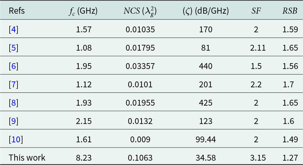
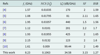
The measured results indicate that the proposed LPF exhibits an insertion loss of less than 1 dB and a return loss better than 15.1 dB across the DC to 7.5 GHz passband. The sharpness parameter  $\zeta$ is given by Equation (10) [Reference Roshani, Yahya, Khazaei, Roshani and Karami10].
 \begin{equation}
\zeta=\frac{\alpha_{max}-\alpha_{min}}{f_s-f_c}
\end{equation}
\begin{equation}
\zeta=\frac{\alpha_{max}-\alpha_{min}}{f_s-f_c}
\end{equation} Where  $\alpha_{max}$ = 40 dB at $f_s$ = 9.3 GHz and $\alpha_{min}$ = 3 dB at $f_c$ = 8.23 GHz represent the attenuation levels of the $S_{21}$ parameter. The sharpness parameter of the proposed filter is 34.58 dB/GHz.
Using equations (11) and (12)[Reference Roshani, Yahya, Khazaei, Roshani and Karami10], the suppression factor (SF) and related stopband bandwidth (RSB) are determined.
 \begin{equation}
\mathrm{SF}=\frac{rejection\;level\;in\;stopband}{10}
\end{equation}
\begin{equation}
\mathrm{SF}=\frac{rejection\;level\;in\;stopband}{10}
\end{equation} \begin{equation}
\mathrm{RSB}=\frac{stopband(20dB\;attenation\;level)}{stopband\;centre\;frequency}
\end{equation}
\begin{equation}
\mathrm{RSB}=\frac{stopband(20dB\;attenation\;level)}{stopband\;centre\;frequency}
\end{equation} \begin{equation}
\mathrm{NCS}=\frac{physical\;size(length\times width)}{\lambda_g^{2}}
\end{equation}
\begin{equation}
\mathrm{NCS}=\frac{physical\;size(length\times width)}{\lambda_g^{2}}
\end{equation} The designed filter exhibits a wide stopband ranging from 9.17 to 40 GHz, achieving an attenuation greater than 31.5 dB. This performance corresponds to an SF parameter of 3.15 and an RSB parameter of 1.27, as calculated from equations (11) and (12), respectively. Furthermore, the normalized circuit size(NCS) is determined using equation (13) [Reference Roshani, Yahya, Khazaei, Roshani and Karami10], where the waveguide length  $\lambda_g $ is evaluated at 8.23 GHz. Table 2 shows the comparison between the proposed LPF with the reported ones.
Performance comparisons between the proposed filter and other works
Conclusion
A high-performance microstrip LPF is proposed by integrating an SIHTR with a pair of asymmetric TSRs. Lumped-element equivalent circuit models of the SIHTR and TSRs are developed to analyze their respective characteristics and advantages. Building upon the low-pass response established by the SIHTR, the TSRs are incorporated to further enhance near-stopband suppression and to broaden the overall stopband bandwidth. The measured results show good agreement with full-wave electromagnetic simulations, confirming that the proposed filter achieves a compact structure, sharp roll-off, wide stopband, high return loss, and excellent stopband attenuation performance. In consideration of these specifications, the proposed LPF demonstrates suitability for integration into broadband spread-spectrum modules.
Acknowledgements
This work was supported in part by the Chongqing Natural Science Foundation under Grant CSTB2022NSCQ-MSX1521.
Competing interests
The authors declare none.

Shuhang Chen was born in Pengzhou, Sichuan, China, in 1997. He received the B.E. degree in Electronic Information Engineering from Southwest Petroleum University, Chengdu, China, in 2021, and the M.S. degree in Electronic Information from the School of Aeronautics and Astronautics, University of Electronic Science and Technology of China, Chengdu, China, in 2025. His current research interests include RF passive devices and metamaterials.

Wentao Pan was born in Zhongwei, Ningxia, in 2001. He is currently pursuing a master’s degree at the University of Electronic Science and Technology of China. His main research interests are RF microwave circuits design and antenna design.

Kai Yang received the B.S. degree in electronic science and technology and the master’s degree in circuits and systems from the University of Electronic Science and Technology of China (UESTC), Chengdu, China, in 1993 and 2000, respectively. In 2001, he was promoted as an Associate Professor with UESTC, where he was promoted as a Full Professor in 2007. In 2002, he was selected as the Academic Outstanding Young Scientist Leader Training Plan of Sichuan Province. In 2003, he was a Member of the National Superconducting Standardization Technology Committee. In 2006, he was selected as a Senior Member of the Chinese Institute of Electronics (CIE). He has authored or coauthored more than 50 papers in international and domestic journals and conferences. His current research interests include high-temperature superconducting circuits and systems, and RF and microwave passive circuits.







 Open access

