

Introduction
The NEEM (North Eemian) deep ice-core drilling was a Danish-led program that included 14 funding nations, initiated in conjunction with the International Polar Year 2007. The primary scientific goal of the NEEM project was to obtain an ice core containing a complete and undisturbed archive of the Last Interglacial climate and beyond in Greenland (NEEM Community Members, 2013). On 27 July 2010, after three seasons of drilling, including set-up, this goal was reached when normal drilling operations in the main borehole were declared terminated at 2537.36 m below the surface.
This paper aims to describe the deep drilling activities at NEEM and to document our experiences with the NEEM deep ice-core drill. The drill and drilling infrastructure at NEEM strongly resembled the NGRIP drilling in design and implementation which itself drew from the Greenland Ice Core Project (GRIP) and from the Hans Tausen (HT) drill design concept (Reference JohnsenJohnsen and others, 2007). As much as possible, hardware from the NorthGRIP (NGRIP) drilling was reused, and design modifications specifically for the lower sections of the NEEM drill arose mainly to account for the new, highly viscous drill fluid used at NEEM. The Estisol-240/Coasol drill fluid mixture introduced at NEEM has a kinematic viscosity 9–15 times higher than the drilling fluids used in previous deep drillings in Greenland and Antarctica (Reference Talalay and GundestrupTalalay and Gundestrup, 1999; Reference Sheldon, Steffensen, Hansen, Popp and JohnsenSheldon and others, 2014a), which made design changes favorable for achieving fast travel speed of the drill in the liquid-filled hole and for maintaining the efficient collection of ice cuttings (chips) in an enlarged chip chamber. While the scope of this paper cannot describe all of the detailed experiences of the NEEM drilling, it should provide a source of information and experience useful to groups using similar drill systems, for both deep and intermediate-depth ice-core drilling projects. A companion paper (Reference Popp, Hansen, Sheldon, Schwander and PantonPopp and others, 2014) describes the activities that resulted in collecting sediments, rock and other basal ice-sheet material in the main borehole an additional 7 m below the final depth of 2537.36 m of the NEEM main core.
The Neem Drilling Site
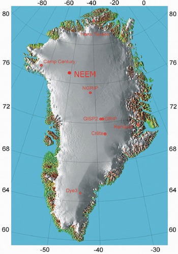
The NEEM site was selected through analysis of available surface elevation data, ice thickness data and ice radar data as the most promising site on the Greenland ice sheet for obtaining an undisturbed ice-core record of the Last Interglacial period and the previous glacial. The site is located at 77.45°N, 51.06°W (Fig. 1), at an altitude of 2484 m, and with an ice thickness of ∼2540 m. The mean annual temperature is −28°C and the mean annual accumulation is 0.22 m ice eq. a−1. Access to the site and the establishment of a seed camp were achieved first via surface traverse from NGRIP in 2007 and later supplied by US National Science Foundation (NSF)-sponsored LC-130 air support provided by the 109th New York US Air National Guard and ground support via the Greenland Inland Traverse (Reference Larsen, Sheldon and SteffensenLarsen and others, 2007, Reference Larsen, Strand, Steffensen and Dahl-Jensen2008). A full NEEM camp became operational during the 2008 field season, including the subsurface drilling trench where all deep drilling infrastructure and support facilities were established (Figs 2 and 3).
Site location of NEEM (77.45° N, 51.06°W) relative to other ice-core sites in Greenland.
The drilling trench at NEEM with the 8.3 m incline trench, heated mechanical workshop, heated control cabin, facilities for core extraction, drill fluid mixing and recycling, and a core logging station (June 2010).

Sigfús J. Johnsen at the helm inspecting the NEEM drill in its horizontal position (June 2009).

The Neem Drill
Descendant of the extended Hans Tausen drill design concept
The NEEM deep drill is a direct descendant of the HT drill and based on the extended NGRIP version of the HT drill. As a prototype, the HT drill was originally tested at Hans Tausen ice cap in 1995, and is described in detail elsewhere (e.g. Reference JohnsenJohnsen and others, 2007). The original design has been modified gradually over two decades and has led to many versions that are nearly mechanically identical to the original prototype, with adjustments largely made to the length of the core barrels and chip chamber. The extended family of HT-type drills go by many names, and have been previously deployed in Greenland including at NGRIP (Reference JohnsenJohnsen and others, 2007), and at several Antarctic sites including EPICA Dome C (Reference Augustin, Panichi and FrascatiAugustin and others, 2007), EPICA DML (Reference Oerter, Drücker, Kipfstuhl and WilhelmsOerter and others, 2009), Berkner Island (Reference Mulvaney, Alemany and PossentiMulvaney and others, 2007), Talos Dome (Reference Mulvaney, Alemany and PossentiMulvaney and others, 2007), James Ross Island (Reference Mulvaney, Triest and AlemanyMulvaney and others, 2014), Fletcher Promontory (Reference Mulvaney, Triest and AlemanyMulvaney and others, 2014) and Roosevelt Island. While significant differences exist in the tower, winch and electronic configurations for some of these systems, the drill mechanics have remained largely faithful to the prototype design.
While the vast majority of drilling at NEEM was done by the long NEEM drill, the HT drill continued to be a useful tool in many different drilling situations. The same drill hardware is capable of drilling in both dry and liquid-filled boreholes. The hardware of the prototype drill itself is still in use and was deployed for the shallowest and deepest parts of the NEEM drilling in the main borehole, including warm-ice and silty-ice retrieval. It was also used to drill a separate intermediate-depth (411 m) ice core at NEEM in 2011, as well as the 423.3 m ice core from Flade Isblink ice cap, northeast Greenland, in 2006 where the new Estisol-240/Coasol drill fluid was field-tested prior to its use at NEEM (Reference Sheldon, Steffensen, Hansen, Popp and JohnsenSheldon and others, 2014a). The prototype hardware was most recently mounted on a new tilting-tower-and-winch configuration and was successfully deployed to drill the main core for the Aurora Basin North project in cooperation with the Australian Antarctic Division (Reference Sheldon, Popp, Hansen, Hedegaard and MortensenSheldon and others, 2014b).
The main design concept for the HT and NEEM drills includes an inner core barrel turning inside an outer core barrel which is held stationary by anti-torque blades positioned at the top of the drill which is suspended from a cable (Fig. 4). As an ice core fills the inner barrel, the space between the barrels provides the pathway for the drilling-fluid-chips mixture (or dry chips) to be carried away from the cutting head to a chip chamber above the core barrel. In one mode, the inner core barrel is fitted with three flights of polyethylene spirals that together with vertical grooves machined along the inner surface of the outer barrel provide the friction necessary to move the chips as the inner barrel rotates. In cases where drilling-fluid circulation is driven by a pump, the spirals need not make contact with the outer barrel, and aluminum spirals of reduced thickness can be used to stir the chips mixture as it is pumped upwards. The inner core barrel turns via a 30 mm diameter hollow shaft which runs through the length of the chip chamber. At its upper end, the hollow shaft is coupled to the drill motor via a gear section at the lower end of the pressure tube, and at its lower end the shaft is coupled to the inner core barrel via a fixed connection or a bayonetted ‘super-banger’ assembly (Reference JohnsenJohnsen and others, 2007). The hollow shaft contains several holes covered by a fine mesh to filter the cuttings from the liquid and provides a pathway that allows clean liquid to be recirculated toward the drill head while cutting, leaving the chips behind in the chip chamber. Specifically for wet drilling, a double-action piston pump with two spring-loaded pistons moving 2 cm in anti-phase can be added at the lower end of the hollow shaft to improve circulation of drilling fluid, particularly in longer versions of the drill design. Otherwise a simple spiral booster placed in the same position moves the chips away from the top of the core barrel and packs them into the chip chamber in both wet and dry drilling modes.
NEEM drill cutaway mock-up showing major sections of the drill sonde.

The normal drill set-up produces a 98 mm diameter ice core and nominal borehole diameters of 126 and 129.6 mm for dry and wet drilling respectively (enlarged to 132 mm for the NEEM drilling, discussed below). The core barrels used for the NEEM drill produced a maximum core length of 3.6 m, and included the barrels still usable from the NGRIP drill as well as new barrels manufactured by H. Rufli at the University of Bern, Switzerland. With all sections connected, plus a 1 m dead-weight section, the total length of the NEEM drill was 13.45 m (Fig. 4).
The anti-torque section and pressure tubes used for the NEEM drill, which included refurbished electronic packages and motor sections, were the same as those used for the NGRIP drilling (Fig. 4). The drill motor is 50 V d.c. running up to 12 A with 60–80 rpm. The drill consumes 250–550 W when cutting ice, which includes turning the piston pump, which adds only ∼30 W due to some added friction. The NEEM set-up also used refurbished surface electronics from NGRIP, but with new power supplies that provided 400 V d.c. from the surface to power the drill and instrument package downhole through a 7.32 mm diameter high tensile steel cable with a single conductor with a diameter of 1.73 mm, where the outer armor is used as the power return. The minimum breaking strain of the cable is 45.8 kN. Communications between the surface and the drill are facilitated by a small communication signal modulated over the power line at 600 baud (1200 b s−1) using a simple ready-to-communicate handshaking.
A new three-phase 15 kW winch motor was mounted at NEEM to start the 2009 season after a fatal failure in the NGRIP winch motor was discovered. Mounted on the same winch drum used at both GRIP and NGRIP, the winch motor has the capability to pull in excess of the breaking strength of the cable (45.8 kN). A new fully programmable winch control system with safety limits was designed to our specifications and built at El-Kas Automation in Denmark. It allowed for very fine control with a continuous feed rate of <0.1 mm s−1 if desired. Together with an excess of 3700 m of cable, the entire winch system and its motor weighs <3 t, and is therefore relatively portable for its function.
Enlarged NEEM borehole diameter to increase travel speed
The high viscosity of the Estisol-240/Coasol drill fluid mixture used for the NEEM drilling made an enlarged borehole diameter desirable to increase travel speed (Reference Sheldon, Steffensen, Hansen, Popp and JohnsenSheldon and others, 2014a). The borehole diameter for most of the drilling at NEEM was increased from the nominal 129.6 mm to 132 mm by extending the width of the cutters by 1.2 mm on their outer edge. Initially, cutters with an even larger kerf that produced a 134 mm diameter borehole were tested, but the excess chip production was sometimes problematic, more so at least than the excess that is already produced by increasing the borehole diameter to 132 mm. It was determined that sufficient gains in travel speeds were achieved with the 132 mm borehole, and when compared to a 134 mm borehole, 3% less drill fluid by volume would be needed overall.
Already, the original HT drill design includes some features to improve travel speeds in a liquid-filled borehole. Most importantly, the end pistons of the chips chamber function as valves mounted on the hollow shaft that can be opened to about one-third of the drill cross section to allow passage of liquid through the core barrel and chip chamber during descent. The largest gains in speed result from allowing the bulk of the liquid to bypass the narrow, high-drag zone between the outer barrel and the borehole wall. The valves are opened and closed with the rotation of the hollow shaft and allow a closed loop for liquid circulation when rotating the drill. Still, by increasing the clearance between the outer core barrel and the borehole wall from 5.8 mm to 7 mm with larger cutters, the piston velocity through the liquid column was further improved (Reference Sheldon, Popp, Hansen, Hedegaard and MortensenSheldon and others, 2014b). Throughout the NEEM project new cutters were manufactured by the group at University of Bern.
Chip chamber modifications for NEEM
To account for the excess chips produced with the larger borehole, a new chip chamber with more volume was needed, and an increase in the filter capacity for the viscous drilling fluid was also desired (Fig. 5). Furthermore, damage to the NGRIP drill chip chamber after its deployment to EPICA DML required it to be cut from the outer core barrel, so a new chip chamber needed to be produced anyway. Even without its chip chamber, however, the 3.6 m NGRIP outer core barrel was still usable and needed for NEEM, so we used the opportunity to reconsider the mode by which the connection should be made between a new, longer chip chamber and the existing outer core barrel. In all previous versions of the HT-type drills, the chip chamber and outer core barrel were welded, forming a junction that corresponds to the position just above the piston pump or spiral chips booster.
The new 6 m long chip chamber designed for the NEEM drill. Includes fingers cut out of its tapered lower end which function to hold the piston pump stationary as the drill turns; 18 000 holes drilled along its body to increase the drill’s filter capacity; and an adaptation for simple assembly with the outer core barrel which replaces the weld junction of previous versions (photograph June 2009).

For the NEEM drill the chip chamber connection to the outer barrel was designed so that the two components could be straightforwardly detached from each other, providing clear advantages for assembly and transport. The tapered lower end of the chip chamber is fitted into the upper part of the outer core barrel and secured using a slotted locking mechanism with brass connectors (Fig. 6). The thickness of the brass connector pieces could be adjusted to also function as centering support for the chamber within the borehole, thus compensating for any additional flex introduced into the system created by this junction. The three fingers that form the tapered lower end of the chip chamber also act as the mounting location for the piston pump, and function to prevent the pump from rotating when the hollow shaft turns. Thus, the often tricky procedure needed to mount the inner pump sleeve in the welded version of the chip chamber was no longer necessary (Fig. 7).
Demonstration of the locking mechanism that couples the chip chamber to the outer core barrel. The tapered lower end of the chip chamber is fitted into the upper part of the outer core barrel and secured using a slotted locking mechanism with brass connectors. The brass connectors are then secured with a screw threaded into the core barrel wall.

The piston pump and sleeve, and the version machined into the tapered lower end of the chip chamber (May 2009).

The chip chamber used for NEEM was 6 m long and was designed to accommodate the chip volume produced with up to 4 m of core and a borehole diameter of 134 mm. Because we eventually settled on a borehole diameter of 132 mm and used core barrels for maximum core lengths of 3.6 m, there was extra volume in the chip chamber which meant that we could never fully fill the chip chamber on a single full run at NEEM.
To improve separation of drill fluid from the chips, 18 000 small holes of 1.4 mm diameter were added along the body of the chip chamber (Fig. 4), thus increasing the filter area of the circulating liquid to include both the hollow shift and the chips chamber barrel itself. This idea was inspired by the same design feature used in the Japanese JARE drill (Reference MotoyamaMotoyama, 2007).
Hollow shaft
Two versions of a 6 m hollow shaft were deployed to accommodate the 6 m chip chamber. A shaft split into two 3 m sections with a center coupling was the first to be deployed, and later, during the 2010 season, a single 6 m shaft was deployed on alternating drill runs. Each version was thought to have its advantages and disadvantages. To use an extreme metaphor, using such a long flexible shaft as the drive shaft could be like turning the drill with a spaghetti noodle. With the two-piece version, stiffness was added by the coupling itself. However, with this set-up there were also concerns that the coupling could create a blockage where chips packed or disrupted fluid circulation flow.
In each case, spiral chip boosters and centering rings could be placed at different points along the shaft to aid in distributing chips evenly throughout the chip chamber, while also guiding the rotation of the flexible shaft (Fig. 8). Their placement could easily be altered to react to changing ice conditions and chip characteristics; however, they could themselves also create blockages, that could in bad cases block the pump and prematurely end a drill run (Fig. 8). Great effort was put into finding the best way to effectively fill the chamber by reconfiguring how these items were placed along the shaft, and while stable modes could be found for many consecutive runs, efficient and consistent chips packing remained an issue for parts of the NEEM drilling. When blockages occurred, no consistent pattern could be found with respect to which hollow shaft was being used or to how spiral boosters and rings were placed. This became a source of frustration for some of the drillers and drill helpers.
Left: The lower end of the hollow shaft with pump and super-banger mounted, with the fine mesh filter not yet installed. A spiral chip booster sits in one of its many positions. Right: Chips packing between the pump and spiral booster (May 2010).

Software
The drill operation switched from the old BASIC version of the drilling software used at GRIP and NGRIP, to a new graphical version (Fig. 9). Adjustments to the software were made throughout the NEEM drilling in response to the desires of the drillers as we learned how to best utilize it. Comprehensive logs, with >5 × 10⁶ data entries, were kept of the various drilling parameters that could later be analyzed to assess drill performance. These log entries contain a fair amount of diagnostic information, including downhole temperature and pressure from sensors within the pressure tube and motor sections, voltage distribution, inclination, rotation speed, hammer position and also a log of crucial information (e.g. drilling current, load cell readings and winch speeds, all of which were also available to the drill operator in real time during drilling). Software-controlled speed limits based on the terminal velocity of the drill were also employed to prevent the cable from spooling faster than the drill could descend in the viscous liquid column.
The drill operator’s winch console and control software made teaching new drillers easy and safe, with fine control and real-time monitoring and feedback from downhole parameters.

Chronology
2008 season: pilot hole to 106 m, reaming, casing and trench infrastructure
During the course of the 2008 field season the pilot hole was successfully drilled, reamed and cased, and the infrastructure in the deep drill trench was established. Operations in the NEEM deep borehole commenced on 30 June after the drill trench was blown to 6 m deep, 5 m wide and 30 m long and covered with timber. The pilot hole was drilled over 4 days to 106 m with the 3 in (7.6 cm) Danish shallow drill and winch. This was followed immediately by the casing operation, also with the shallow winch. The casing is composed of several connected sections of fiberglass tubes with a nominal inner diameter of 200 mm, an outer diameter (OD) along its length of 220 mm, and up to 275 mm OD where the tubes are enlarged to overlap at the connection. Each individual section of the casing is sealed with a double O-ring, and the sections are held together by a steel wire set into a groove (Reference Johnsen, Gundestrup, Hansen, Schwander and RufliJohnsen and others, 1994). To accommodate the fiberglass casing tubes, five reaming steps were required to incrementally enlarge the borehole diameter to 281 mm from 104 mm produced by the shallow drill. Previous casing operations with similar tubes at GRIP and NGRIP ensued with four reamer sets (Reference Johnsen, Gundestrup, Hansen, Schwander and RufliJohnsen and others, 1994), but a new fifth reamer needed to be quickly designed and fabricated in Copenhagen when it was discovered that the OD of the upper end of each casing section was up to 20 mm greater than the expected 255 mm. To establish a liquid-tight barrier at the base of the casing, the deepest tube was set with double O-rings at its lower end and sunk tightly into a 222 mm diameter section of the borehole created by the third reaming step at 87.0 m depth. A video camera deployed downhole clearly showed (1) the ledges created along the borehole wall from each of the different reamer diameters, (2) that the lowermost casing tube did indeed set tightly, and (3) that the level of chips filling the remaining depth in the borehole below the bottom of the casing would require that 13 m of chips be removed before drilling could proceed.
Meanwhile, the foundation beams for the tower and winch were placed and the 8.3 m incline trench was excavated as preparation for the placement of the drill tower and winch for the long drill. The tower, which was also used at both the NGRIP and GRIP drillings, was extended by 1.5 m on both ends to account for the greater total length of the NEEM drill (13.45 m). The winch was placed on a foundation of strong wooden beams connected with the tower base. When the winch motor was connected to the winch controller we discovered a malfunction in the winch control that could not be repaired on site, and the test of the new NEEM drill would need to wait until 2009. For the remainder of the season a warm workshop was built and supplied with most of the tools needed for repairing and maintaining the drill and many other camp facilities, including a drill press, bench-top lathe, and milling machine. Several other structures including a grated floor, heated operator’s cabin, working tables, liquid-mixing station and ventilation were installed, and the infrastructure for ice-core extraction and logging established.
2009 season: production drilling to 1758 m
The 2009 season was highlighted by (1) an accidental replicate drilling while performing cleaning runs to remove chips produced during the 2008 casing operation, (2) the successful transition to wet drilling, and (3) production drilling reaching 1758 m with the NEEM deep drill, while learning to tune the drill to efficiently move and collect excess chips created by the expanded borehole diameter in the viscous Estisol-240/Coasol drilling fluid. The cause of the winch control failure in 2008 was eventually traced to a fault in the winch motor. Once the new winch motor was mounted and the winch controllers were successfully repaired, operations began in the pilot hole by 15 May.
‘Replicate’ drilling
The HT drill was connected to the deep winch and cable to begin clearing the 13 m of chips that blocked access to the bottom of the borehole following the previous season’s reaming operation. Beginning with cutters that produce a 134 mm diameter borehole, after three runs ∼40 L of loose chips were brought to the surface. With the fourth run the drill began to penetrate the side-wall and thus deviate from the original borehole with still >10 m remaining before reaching the bottom of the existing borehole. On this run, together with an excess of chips, a sliver of virgin ice was brought to the surface (Fig. 10). Forced by the slight inclination in the borehole (<1°), side-wall penetration began when the cutters encountered the ledge left by the transition between the second and third reamer diameters. On the next run we mounted the conical reamer in place of the drill head with the idea that its long edges would smooth the ledges and direct the drill back into the original borehole. After two runs with the reamer, we mounted the drill head with cutters with a reduced kerf to see if we could re-enter the original borehole. Instead, 1.32 m of ice core in the shape of a crescent moon was brought to the surface, growing in diameter with depth as the drill increasingly deviated. This second moon-shaped core also contained the ledge formed by the transition between the first and second reamer diameters. Committed now to the new borehole, we could determine by the shape of the ‘crescent moon’ core that within another meter of penetration a complete new borehole would be established at ∼99 m depth. We remounted the wide cutters and simply decided to continue. The new borehole was more plumb than the original pilot borehole and had an inclination of ∼0.3°. The depth registration of the new core could be precisely aligned with the overlapping section of the original pilot core by using common features in electrical conductivity measurements and water stable-isotopic composition.
The first ‘crescent moon’ core resulting from deviation from the pilot hole (May 2009).

Transition to wet drilling and the NEEM drill
Once the new borehole was deep enough to accommodate a longer drill, the lower part of the HT drill was replaced with the longer core barrels and chip chamber used at EPICA Dome C provided by the Laboratoire de Glaciologie et Géophysique de l’Environnnement (LGGE), Grenoble, France. The field-tested EPICA barrels were deployed for several days while the NEEM drill chip chamber, hollow shaft, and core barrels were being made ready and assembled on site. At this point the depth below the surface was ∼118 m and drill fluid was added to the borehole. Using the EPICA barrels was not ideal, however, because the 3.5 m core barrel could only contain 2–2.5 m per run, before its 4 m chip chamber was full due to cutting a wider kerf. At 161 m, we made a permanent shift to cutters that produce a 132 mm borehole diameter. We continued in this mode with the EPICA barrels until a depth of 206 m, after which the NEEM drill made its first run. For the remainder of the season we used the NEEM drill with a 3.5 m core barrel and 6 m chip chamber, performing 499 runs with a maximum core length of 3.5 m per run.
Learning by drilling
Throughout the season there were significant efforts to learn how to best configure the cutting pitch and how to position the combination of spiral chip boosters and centering rings along the 6 m hollow shaft to best collect and distribute the chips in the chip chamber. The dynamic situation required constant attention. Once a stable mode was eventually found, it would last for several days at a time, but would disappear with increasing depth as the character of the ice and chips changed. A few patterns, however, did emerge. Typically, runs would end with high motor current that had been gradually increasing throughout the run as the chips began to pack in the chip chamber (Fig. 11). When a blockage of packed chips formed either within the pump, or at a spiral chip booster, centering ring or hollow shaft junction, an acute rise in motor current could prematurely end the run before filling the core barrel (Fig. 12).
Plot of motor current and load cell (proxy for weight on bit) from a typical ‘good’ run collecting a full-length ice core. The gradually rising current is indicative of chips packing in the chip chamber. The drop in motor current at the end is a result of losing contact with the ice and the drilling spinning idle.
Examples of chips packing in an unproductive way. Upper panel shows an example where drill fluid was forced to pass through the chips mass during a core break creating the channel. The dotted surface of the chips mass was formed by the small holes in the chip chamber body. Lower panel shows an example where the pump was completely packed and disengaged (May 2010).

A standard remedy to prevent packing is to produce coarse chips by increasing the cutting pitch. We learned that with the wider kerf cutters we could manage to cut with a pitch of only up to ∼3.2 mm when we began wet drilling, and later with increasing depth only up to ∼2.5 mm, before we reached the power limitations of the drill system. With a fine balance between producing coarse chips and available power, we eventually targeted between 2 and 3 mm cutting pitch depending on how the previous runs had been behaving. A typical run would also show that effective cutting pitch (as measured from the core on the surface) would decrease throughout the run, ending in some cases lower than 1.5 mm. As had been common practice in the NGRIP drilling, we tried to drill with negative cutter load, but found we typically needed on the order of 50–150 N of load on bit to penetrate at NEEM, again with increasing values as the run progressed. Drilling with a lower than optimal pitch might be able to explain why the drill could not ‘grab’ to the ice and pull its way down as had been the case for much of the NGRIP drilling.
Improvements in drill performance almost always occurred when we were sure we had both a clean borehole and a clean hollow shaft. Short runs seemed to be plagued by extra chips in the borehole, in particular if a long core had been picked up on a previous run but had poor chips recovery. Extra chips in the hole could eventually clog the hollow shaft if not diligently cleaned, but once a procedure was set up to clean the inside of the shaft between each run, improvements were noted. Occasionally the liquid column in the borehole would be filtered with a downhole filter, or by closing the valve at the top of the chip chamber upon descent with the drill.
While we do not have a satisfactory explanation for all of these behaviors, we nevertheless ended in a very productive stable mode, finishing the season at 1757.84 m. Routine drilling was established to cover two shifts covering 16 hours per weekday and 10–12 hours per day Saturday and Sunday. Once this two-shift routine was established with the long NEEM drill, maximum daily production was 37 m d−1 and median daily production was 21 m d−1.
2010 season: production and warm ice drilling to ‘bedrock’ at 2537.36 m
The main highlight from the 2010 season is that drilling of the main NEEM core was declared terminated on 27 July 2010 at 2537.36 m depth, when no further penetration was possible with the available equipment. To start the season, the tower was reinforced with a second linear motor to increase tilting power. This was necessary because the existing system was not adequate for tilting an unbalanced load on the tower after it had been extended to account for the longer chip chamber. Several days at the beginning of the season were also dedicated to filtering the hole in order to recover chips left in the borehole from the previous season. This operation yielded >200 kg of chips before drilling started, and was profound evidence that we lacked efficient chips recovery during the 2009 season. We noted, however, the nice characteristic that the chips remained suspended in the drilling fluid and thus did not collect near the bottom of the borehole, as had been an issue at times with using the kerosene-based drilling fluids mixed with an HCFC liquid as a densifier, encountered for example at NGRIP (Reference Gundestrup, Johnsen, Hansen, Shoji, Talalay and WilhelmsGundestrup and others, 2002; Reference JohnsenJohnsen and others, 2007).
To begin with, the drill itself was configured exactly the same as it had been at the end of the 2009 season, but with different results. In 2010, overall maximum production reached only 20 m per drilling day with median production of 15.5 m per drilling day until basal ice was reached. In addition to longer run cycle times simply due to increasing depth (Fig. 13), several weeks of start-up issues contributed to slower overall production. First, under normal operations of the drill at the start of the 2010 season the inner core barrel was lost three times in the hole during descent when the bayonet connection allowed the core barrel to come free from its connection to the hollow shaft. This was caused by a very slight reduction in the borehole diameter (±0.1 mm) at depths where the cutters mounted on the cutting head had been changed in the previous season. The added friction from the cutters contacting the borehole wall at these spots can cause the core barrel to turn in reverse during descent. Because the bayonet geometry is designed such that reverse rotation is used when the intention is to release the barrel, it also makes it susceptible to accidental release in some cases during descent. For this reason, the lowest 800 m of the hole (1000–1800 m depth) was reamed with the drill to increase the borehole diameter by ∼0.1–0.2 mm. Alternate geometry for the bayonet will be implemented in future core barrels, as the incidents of accidental lost core barrels outnumber the cases in which the bayonet was used for its intended purpose to assist in hard core breaks or to free a stuck drill. Nonetheless, the core barrels were easily retrieved from the bottom by removing the chip chamber and outer core barrel from the drill at the surface and then descending again using the hollow shaft with the male end of the super-banger as a fishing probe to re-engage the connection of the bayonet at the top of the lost core barrel and pull it back to the surface.
Drilling cycle time for a complete run including tripping (blue) and the time spent with the drill motor turning downhole (red). The vertical blue line indicates the transition between the 2009 and 2010 seasons.

Meanwhile, as had been the case in 2009, many different configurations of the hollow shaft were used (e.g. two-piece hollow shaft, one-piece hollow shaft, centering rings at different places, and various spiral boosters). We could still not conclude what was the ‘best’ configuration, and the behavior seemed to be erratic, but almost always symptomized by the distribution of chips in the chip chamber, either through the loss of chips in the borehole or blockages that prevented further penetration. Eventually, placing the centering rings on the hollow shaft spaced at 4.5 m (i.e. one placed 1.5 m above the pump and the other placed 1.5 m below the upper valve) gave the most consistent chips distribution in the chip chamber. Overall, the cutting pitch was between 1.5 and 2.8 mm, again with the larger pitch producing better, coarser chips, but also requiring that drilling proceed at the upper limit of the power available from the electronics/motor section. In general, cutting with wider kerf cutters placed the system near the power limit of the motors deployed to NEEM, and made it necessary to cut with a lower pitch than otherwise would be optimal.
Warm ice
The difficulties drilling warm ice that characterized the deepest parts of the NGRIP (Reference Gundestrup, Johnsen, Hansen, Shoji, Talalay and WilhelmsGundestrup and others, 2002; Reference JohnsenJohnsen and others, 2007) and EPICA (Reference Augustin, Panichi and FrascatiAugustin and others, 2007) drillings were largely not present at NEEM, in part due to the Estisol-240/Coasol drill fluid mixture (Reference Sheldon, Steffensen, Hansen, Popp and JohnsenSheldon and others, 2014a). The oily and viscous nature of the liquid seemed to prevent chips and refrozen water from packing and building up on the surfaces of the cutters and shoes, processes which caused the penetration problems and stuck drills in the former drillings.
As we approached the deep, warm depths the long barrels of the NEEM drill were replaced with the lower part of the HT drill with its 1.6 m core barrel and 1.6 m chip chamber. The shorter chips transport pathway relative to the NEEM deep drill increased pumping efficiency and liquid circulation for clearing the drill head and improved chips packing in the chip chamber. When combined with injections of ethanol around the drill head, such a configuration was beneficial in warm-basal ice drilling at NGRIP (Reference JohnsenJohnsen and others, 2007). Although the procedure of injecting ethanol downhole never needed to be employed at NEEM, warm ice drilling was largely, but not entirely, trouble-free.
As was the case at least seven times at NGRIP (Reference JohnsenJohnsen and others, 2007), on one occasion it was necessary to deploy frozen pellets of pure ethylene glycol into the borehole to free a stuck drill. At 2423.14 m depth, pulling up with the winch using 23 kN did not free the drill. A total of 2.3 kg of frozen glycol pellets were dropped into the hole from the surface. After a little more than 2 hours, the pellets melted in the warm, deep part of the hole where they dissolved the ice or chips packing at the drill head to release the drill.
For the final runs, step cutters (cutters with partial kerf; e.g. Reference Zagorodnov, Thompson, Ginot and MikhalenkoZagorodnov and others, 2005) were mounted (Fig. 14). At this point we had lost the ability to penetrate with our normal cutters, as they would not bite due to ice build-up under the shoes behind the cutter. Together with the partial kerf step cutters, we modified the shoes to have very little contact surface with the ice to try to prevent these surfaces from collecting refrozen water (Fig. 14). With this set-up, penetration continued, producing coarse chips that moved efficiently away from the drill head without packing there, while at the same time requiring less power to cut the same amount of ice. Using these cutters and shoes also effectively avoided the need to inject ethanol around the drill head to otherwise prevent the ice build-up. Although used for only a very short time, it would seem that drill characteristics observed using partial kerf cutters suggest that their use could also be recommended for an entire drilling campaign. Drilling in this mode, the last meters of core brought up were rich in debris, including cores containing small stones and with several layers of silty ice banded with clear glacial ice (Reference Popp, Hansen, Sheldon, Schwander and PantonPopp and others, 2014). Finally drilling was stopped when further penetration was obstructed by a stone in the path of the drill head at 2537.36 m.
Partial kerf (step) cutters (photograph July 2010).

Assessing Performance and Conclusions
The overall good core quality and fast production at NEEM could not have been achieved without significant periods of stable drilling and good chips collection. However, when considering the drilling experience at NEEM or elsewhere, we usually learn more from situations when something is not working at its best and we tend to focus on these. Probably the most important consideration for drilling at NEEM was that the nature of the ice, the cutting pitch and size of the chips influenced the way the chip chamber was filled and whether a full run producing a 3.5 m ice core could be achieved. Comparing the performance at the end of 2009 with the start of 2010 (Fig. 15) using the same drill set-up demonstrates that tipping points in chips transport in our system are small and we cannot claim to completely understand the fluid flow. What worked well one season was not effective the next, and what worked well one day was not always effective the next, usually due to dealing with the chips. An example of a promising way forward was when we used step cutters as we approached the bottom. Coarse chips were generated that efficiently filled the chip chamber without blockage, while at the same time using less power. This situation was not unique to step cutters, however, as the traditional cutters also did a sufficient job for most of the runs in producing good-quality ice cores of maximum length.
Core length versus depth. Individual runs given by the black symbols, with a running average given by the red line. The vertical blue line indicates the transition between the 2009 and 2010 seasons.

The placement of spiral boosters and centering rings along the hollow shaft was always driven by the need to effectively collect the chips and to prevent blockages from forming that ended runs prematurely. Together with changes to the cutting pitch, these were the variables we had to work with in response to the changing ice conditions during production drilling. In this context, though, we are happy with the pump design, because in situations where poor chips transport or inefficient packing in the chip chamber leads to the pump itself becoming completely packed with chips, the pump does not become damaged as drilling continues. Since the pump action works by compression of its springs it simply stops pumping, as the springs are inhibited from compression while continuing to rotate passively along with the hollow shaft.
The danger of inefficient chips collection and transport is not only loss of runs or reduced core lengths, but also the risk of the drill becoming stuck. In a situation with a completely clogged hollow shaft, together with chips packing at the cutting head, there is the risk that, during a core break, there is no place for the liquid to go as the drill tries to ascend. Essentially a suction can be created below the head as the drill is required to try to lift the entire liquid column. In the top panel of Figure 11 an example of this can be seen, where a channel was created in the tightly packed chips as the liquid forced its way through during a core break. The strength of the core break itself is shown in Figures 16 and 17. The approximately normal distribution of break strengths indicates that there was not a strong relationship to depth during the NEEM drilling. Nevertheless, though they were infrequent, the instances when >10 kN was needed to break the core increasingly occurred below 1800 m, and were most easily observed in the final runs near the base (Fig. 16; Reference Wilhelms, Sheldon, Hamann, Kipfstuhl and KuhsWilhelms and others, 2007).
Core break strength versus depth in the borehole.

Histogram of core break strength.

Another way of assessing the performance of the drilling operation at NEEM is by the speed of ice-core production. The amount of time spent drilling is fairly constant with depth, but the time spent overall increased with depth, as expected (Fig. 13). In part due to the Estisol-240/Coasol drilling mixture, the travel time was a concern, with the top speeds achieved and averages shown in Figure 18.
Maximum and average speeds of the drill through the liquid column. Descent shown in the upper panel, and ascent in the lower panel. Blurring around averages represents the cloud of data that compose the averages. The speed limit in the casing both ascending and descending (upper ∼100 m) set by rule for the operators. Descent speed below 100 m was a software-controlled speed limit based on the terminal velocity of the drill employed to protect the cable from spooling faster than the drill could descend in the viscous liquid column.

The main bottleneck is the terminal velocity of the drill on the way downhole. The decreasing descent speed with depth was due to a procedural speed limit set for the operators that erred on the side of caution after an incident in early 2009 when the cable was kinked when the winch payout rate exceeded the speed the drill could achieve in the borehole. In previous drillings (e.g. NGRIP) the operator adjusted descent speed based on a cutter load sensor within the anti-torque section, which more literally can be described as the position of the sliding anti-torque hammer as measured by a linear transducer. Movement of the hammer position indicated when the cable went slack as the payout rate exceeded the descent speed of the drill in the borehole. This system failed to operate in a viscous Estisol-240/Coasol fluid-filled borehole at NEEM, which inhibited free movement of the sliding hammer unless totally engaged with an obstruction or the bottom of the borehole, even at depths where increasing borehole temperature decreased the liquid viscosity. Therefore, in order to guide the operator, the descent speed limit was set based on an estimate of the weight of the drill plus the weight of cable per meter spooled out as detected by a load-cell pin mounted on the shaft of the cable wheel sheave at the top of the tower. This ensured that there was some tension on the cable at all times during descent. For this simple calculation the weight of the free-hanging drill in drill fluid was set to 154 kg and a conservative value of 0.18 kg m−1 cable spooled out was used to estimate the predicted hook load of a stationary drill in the liquid at a given depth. With the drill in motion, resistance in the liquid column removed cable tension, giving a lower reading at the top wheel load pin. A visual and audible warning to slow down was sent to the drill operator via the software if the floating drill could not be detected. We tried to maintain at least 10 kg of detectable load over that of the cable spooled out.
The speeds going up are much higher when the drill is pulled up by the winch providing the external force to overcome the liquid viscosity. The hoisting speed was increased in 2010 relative to 2009 by adjusting a setting in the winch control to provide more power when pulling up. Upon hoisting, a sustained force of ∼9–12 kN was required to maintain 1–1.3 m s−1 ascent speed throughout the liquid column.
Another aspect of production rate and drill performance is the amount of core pulled up each run. The distribution with depth can be seen in Figure 15. It is clear that the 2009 season produced a majority of long cores (3.0–3.5 m), whereas for the 2010 season the distribution of core lengths is quite varied, producing shorter cores (2.0–2.5 m) on average, both during the start-up phase and as warm ice was encountered near the bottom. This difference in core length is reflected in the overall daily and weekly production rates, where weekly production during two-shift routine drilling averaged ∼150 m in 2009 and only 105 m in 2010.
Overall, adapting the NEEM drill to the new drilling fluid was largely successful, and we maintained our usual productive drilling rate with good core quality. For future drillings we will want to improve our brittle ice collection, which was not optimal at NEEM, largely because of conditions in the trench and due to core extraction rather than the drill itself. Finally, NEEM also served as a platform for groups developing their own drilling capabilities via their individual experiences at NEEM or through the development of similar drilling equipment that could be tested on site. This valuable exchange of diverse experience and learning was a big part of what made the NEEM drilling unique and special.
Acknowledgements
We are enormously grateful for the support of Jakob Schwander (University of Bern, Switzerland) for his continued partnership in all matters related to drilling, science and our discussions. We thank all partners in the EUROPICS framework of ice-core drilling for our yearly discussions, and our particularly fruitful cooperation with Henri Rufli and others in the Bern group; Olivier Alemany and his group of mechanics and drillers at LGGE; Martin Leonhardt and the gang at Alfred Wegener Institute, Bremerhaven, Germany; the dozens of other drill helpers, mechanics and engineers that participated in the NEEM drilling; and the logistics support and leadership that made the NEEM project possible. NEEM is directed and organized by the Center for Ice and Climate at the Niels Bohr Institute and US NSF, Office of Polar Programs. It is supported by funding agencies and institutions in Belgium (FNRS-CFB and FWO), Canada (NRCan/GSC), China (CAS), Denmark (FIST), France (IPEV, CNRS/INSU, CEA and ANR), Germany (AWI), Iceland (RannIs), Japan (NIPR), Korea (KOPRI), The Netherlands (NWO/ALW), Sweden (VR), Switzerland (SNF), the UK (NERC) and the USA (US NSF, Office of Polar Programs).


