
I. INTRODUCTION
In recently finalized release-15 5Gnew radio (NR) access technology standards by 3rd Generation Partnership Project (3GPP), two new physical-layer channel coding schemes of polar and low-density parity-check (LDPC) codes have been introduced to replace convolutional and Turbo codes used for 4G long-term evolution (LTE). According to the 3GPP technical report 38.913 [1], there are three main 5G usage scenarios ofenhanced mobile broadband (eMBB), ultra-reliable and low latency communications (URLLC), andmassive machine type communications (mMTC). These scenarios require improved throughput, latency, and reliability compared with a 4G system. In addition to this, similar to a 4G system, 5G channel codes should also support a variable code rate and length for both control information and user data as well as hybrid automatic repeat request (HARQ) for user data. During the study phase of 5G standardization, the objectives of which were described in [2], many coding schemes including 4G's were evaluated based on the aforementioned requirements, and LDPC coding has been adopted for user data while polar coding has been adopted for control information of the eMBB scenario as well as for the release-15 scope of the URLLC scenario focusing on low latency in 5G cellular communications; 3GPP evaluation summary can be found in [3, 7.1.3]. The 3GPP specification work is currently being done for further enhancement of URLLC and will be done in future for 5G mMTC.
LDPC codes were originally defined by Gallager [Reference Gallager4], and a parity check matrix of LDPC codes can be represented by a bipartite graph as described in Fig. 1. Low density in a parity check matrix corresponds to a sparse graph representation, and such sparsity can result in low decoding complexity when message passing decoding is applied. Sucha possibility of efficient decoding is an important factor in practical deployment scenarios. In addition to applicability of efficient decoding, LDPC codes are shown to achieve capacity of memoryless, binary-input, output-symmetric (MBIOS) channels in theory [Reference Shokrollahi5–Reference Hsu and Anastasopoulos9]; an MBIOS channel is characterized by transition probability p Y|X (y|x) which satisfies p Y|X(y|0) = p Y|X ( − y|1) for X ∈ {0, 1} and  $Y\in {\cal Y}$ where ${\cal Y}$ can be either discrete or continuous. As will be described later in this paper, there are a few important characteristics of 5G LDPC codes which resemble those of capacity-achieving LDPC codes.
Graph representation of LDPC parity check matrix.
5G deployment scenarios, especially the eMBB case, require the support of high throughput which can be up to 20 Gbps, and encoding and decoding process of 5G channel codes especially for data needs to be designed to handle this. 5G LDPC codes adopt the structure of quasi-cyclic (QC) LDPC codes [Reference Fossorier10] which naturally enables parallelism in encoding and decoding [11], and high-throughput encoder and decoder can be realized by such parallelism. 5G channel codes for data should also support HARQ, and 5G LDPC codes are designed to efficiently support incremental redundancy (IR) HARQ. As will be described later, such IR-HARQ design of 5G LDPC codes effectively reduces the size of encoding and decoding graph when the operating code rate is high, which also helps the realization of high throughput. Rate compatibility to select an arbitrary amount of transmitted bits from mother code output and a variable code length are other important functionalities of 5G channel codes, and the 5G LDPC design realizing such functionalities will be described later in this paper. Fig. 2(a) describes an encoder/transmitter processing chain of 5G LDPC codes.
Encoder/transmitter processing chain of 5G LDPC codes and polar codes. (a) LDPC codes, (b) polar codes.
Polar codes were originally defined by Arikan [Reference ArÄśkan12] who proved capacity achievability on MBIOS channels. Unlike the capacity achievability of LDPC codes which relies on ensemble average performance, the capacity achievability of polar codes can be proved with a specific realization. Moreover, simple successive cancellation (SC) decoding is enough to achieve capacity. One of the main aspects of polar code design is the determination of the information sequence, i.e., determination of information and frozen bit positions. While such a procedure can be done in a recursive form of simple closed-form equations for the binary erasure channel (BEC) [Reference ArÄśkan12, III.B], it is numerically involved for more general channels like additive white Gaussian noise (AWGN) channel [Reference Mori and Tanaka13,Reference Tal and Vardy14].
In a practical system, one possible way to avoid the aforementioned numerical challenge for information sequence determination would be to store the precomputed information sequence. However, information sequence can also depend on parameters like signal-to-noise ratio (SNR), code length etc., so a compromise needs to be made to limit the number of different information sequences. In 5G, a single information sequence is adopted to be applied for all cases. Similar to codes for data, 5G channel codes for control should support rate compatibility through a process of rate matching. Note that some information bit positions originally determined by the information sequence may become unusable due to rate matching, and it will be described later in this paper how 5G polar codes efficiently adjust information bit positions acknowledging it. There are additional requirements for control information compared with data due to the fact that control information is typically transmitted witha smaller amount of information bits and with a shorter codeword length. Control information is also typically transmitted with lower code rate while good performance in lower BLER regime is required. 5G polar codes are designed to satisfy these requirements. Adoption of polar codes for control information is reasonable especially considering low BLER application given the fact that polar codes are analytically shown not to suffer from error floor [Reference Mondelli, Hassani and Urbanke15].
While the capacity achievability of polar codes with simple SC decoding is attractive, its finite length performance with SC decoding is shown to be noticeably worse than other channel coding candidates [Reference Tal and Vardy16]. A well-known solution for such a concern especially for polar codes is list decoding [Reference Tal and Vardy16]. Simply speaking, successive cancellation list (SCL) decoding tries to overcome the fundamental drawback of premature decision of SC decoding by keeping multiple decision candidates throughout SC decoding process, i.e., by not making a firm decision during SC decoding stage. To further improve BLER performance of SCL decoding, CRC-aided (CA) SCL [Reference Tal and Vardy16] is considered in which CRC is used not only for error detection but also for error correction. Another concern with SC decoding is its latency issue, and there are several practical solutions reducing latency of SC decoding [Reference Sarkis, Giard, Vardy, Thibeault and Gross17–Reference Fan19]. In addition to such an implementation-specific effort, 5G polar codes adopt distributed CRC to support early decoding termination. Fig. 2(b) describes an encoder/transmitter processing chain of 5G polar codes.
The remainder of this paper is organized as follows. Section II describes the main characteristics of 5G LDPC codes while Section III describes details of 5G polar codes. Section IV describes performance of 5G LDPC and polar codes. Section V concludes the paper.
II. 5G LDPC CODES
In this section, we describe the main characteristics of 5G LDPC codes. 5G LDPC codes are QC-LDPC codes which belong to a family of protograph codes. Design of a permutation matrix, as well as design of the protograph, are important aspects for protograph code design, and these will be explained in detail. Rate matching procedures for rate compatibility as well as support of IR-HARQ will also be described.
A) Protograph codes
5G LDPC codes belong to a family of QC-LDPC codes [Reference Fossorier10], and QC-LDPC codes can be explained by using a concept of protograph codes. Fig. 3 describes a procedure of constructing a long protograph code by using a small protograph. Simply speaking, a graph representation of protograph codes can be obtained by attaching multiple copies of the protograph and by then permuting edges across them. To perform permutation of edges, like variable and check nodes are first identified from each copy of the protograph, and edge permutation only happens among these like nodes. A process of attaching multiple copies of the protograph and permuting edges is called lifting, and the number of attached copies of the protograph is called lifting size which is typically represented by a variable Z. For LDPC codes, local connection among variable and check nodes are important to ensure good performance, and this permutation procedure enables constructing long codes by connecting multiple copies of the small protograph while maintaining local connection characteristics of it, e.g., if a check node (or a variable node) in the protograph in Fig. 3 is connected to edges with a group of colors, then the corresponding check node (or the variable node) would still be connected to the edges with the same group of colors after the long protograph code is constructed. Designing a good permutation pattern with a good cycle property is also important for the performance of protograph codes. There have been multiple observations showing that protograph codes achieve good finite length performance in various environments [Reference Fang, Bi, Guan and Lau20]. In addition to ease of constructing good codes with longer length, protograph codes enable natural parallelism in encoding as well as in decoding [11], which is beneficial when layered decoding [Reference Hocevar21] is applied. In layered decoding, each check node or variable node is processed sequentially during each decoding iteration unlike a flooding schedule in which messages at all check nodes are updated simultaneously (in parallel) during one half of a decoding iteration and vice versa for all variable nodes during the other half of the iteration. Layered decoding typically expedites convergence time in terms of the number of decoding iterations, but it is not typically parallelized, unlike a flooding schedule. With protograph codes, however, the like nodes from every copy of the protograph can naturally be processed simultaneously without affecting the performance of layered decoding. Such parallelism, especially at decoding, hasa crucial impact for high throughput support. When parallelism of the size equal to the lifting size is applied at the decoder, the decoding latency of a very long code with a large lifting size would not be worse than that of a very short code with a small lifting size, i.e., the decoding latency is governed by the size of the protograph not by the actual code length.
Construction of protograph codes; permutation is applied for like-colored edges.

In the 5G specification [22, 5.3.2], a protograph is officially called a base graph, and there are two types of base graphs whose usage is determined by code rate or a size of information bits. A parity check matrix of protograph codes can be constructed from the base graph by replacing each zero-valued entry with a Z × Z all-zero matrix and each non-zero-valued entry with a Z × Z permutation matrix. QC-LDPC codes can be considered as protograph codes whose permutation is only allowed to be a circular shift. In other words, a permutation matrix of QC-LDPC codes is a circularly-shifted identity matrix. One of the main benefits of having a circularly-shifted identity matrix as a permutation matrix is that each permutation is represented by a single number. This greatly reduces the memory requirement for implementation while also facilitating the use of a simple switch network for encoding and decoding [Reference Lee and Liu23].
In the 5G specification, 51 different lifting sizes are defined, and there are eight different permutation matrix designs per base graph as described in Table 1. The factors considered for determination of lifting sizes are the amount of possible parallelism and the associated switch network complexity. Note that the support of a variable code length can efficiently be done by simply choosing the appropriate lifting size based on the information bit length to be encoded [22]. A lifting size is selected such that it is close to the number of information bits divided by the number of base graph columns corresponding to information bits; the number of base graph columns corresponding to information bits is 22 for base graph 1 and 10 for base graph 2. The set of permutation matrices which determines the permutation matrix for every non-zero-valued entry of the base graph is selected according to Table 1 for each lifting size [22]. The permutation matrices, i.e., the circular shift values, in the 5G specification are described for the maximum lifting size corresponding to each set of permutation matrices, and a modulo operation of the circular shift value by the chosen lift size is applied to obtain the shift value for the smaller lifting sizes. Due to this nature, different lifting sizes having the same set of permutation matrices can be considered as the same family of LDPC codes.
The relationship between shift-value sets and lifting sizes for 5G LDPC codes
B) Base graph design
In addition to the design of the shift values, the design of the base graph which governs good local connection among variable and check nodes is important to ensure good performance of LDPC codes. Before describing details of 5G LDPC base graph design, let us discuss the capacity achievability of LDPC codes. LDPC codes are proved to achieve capacity of MBIOS channels, and such capacity achievability is in average sense over an ensemble of codes. An ensemble is typically defined by degree distribution of variable (λ(x)) and check (ρ(x)) nodes.
 $$\lambda(x) = \sum_{i} \lambda_i x^{i-1},$$
 $$\rho(x) = \sum_{i} \rho_i x^{i-1},$$
where λi (ρi) gives fraction of edges connected to variable (check) nodes with degree i. In other words, λi (ρi) is the probability that an edge chosen uniformly at random from the graph is connected to a variable (check) node of degree i. An ensemble of LDPC codes which is defined by the above λ(x) and ρ(x) is called a standard ensemble. It is called regular if both λ(x) and ρ(x) consist of a single term and is called irregular otherwise. Unfortunately, it is shown [Reference Sason and Urbanke24] that a standard ensemble cannot achieve capacity of MBIOS channels unless its parity check matrix density grows to infinity with respect to code length. One thing to note is that such a negative result does not necessarily hold when modification of the standard ensemble, e.g., introducing punctured variable nodes, introducing multiple edge types such as an accumulator portion in irregular repeat accumulate (IRA) codes, is applied [Reference Richardson and Urbanke25, 7.1], and several LDPC codes [Reference Pfister, Sason and Urbanke7,Reference Hsu and Anastasopoulos9] are shown to achieve capacity of MBIOS channels with finite density.
In this sub-section, we describe details of 5G LDPC base graph design while providing relationship to the capacity-achieving LDPC codes. The structure of the 5G LDPC base graph can be explained by using Fig. 4 which describes base graph 1 whose size is 46 × 68 with mother code rate of 1/3. The structure of base graph 2 whose size is 42 × 52 with mother code rate of 1/5 is similar to that of base graph 1. The first 22 columns of base graph 1 and the first 10 columns of base graph 2 correspond to information bits. Note that the first two columns of both base graphs are not transmitted, i.e., they are always punctured.
5G LDPC base graph 1.
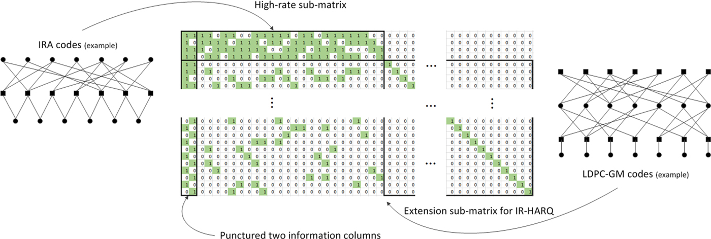
1) High-rate sub-matrix as IRA codes
The high-rate sub-matrix of base graph 1 which corresponds to the first 4 rows and the first 26 columns of Fig. 4 has a structure of IRA codes. As described by an exemplary graph representation in Fig. 4, IRA codes are constructed by concatenating irregular LDPC codes and an accumulator which is represented as a dual-diagonal structure. In [Reference Pfister, Sason and Urbanke7], IRA codes are shown to achieve capacity of BEC with bounded graphical complexity, i.e., the number of 1's in parity check matrix divided by the number of information bits. There also is an implementation benefit of the IRA structure since it enables efficient encoding [Reference Cai, Hao, Tan, Sun and Chin26]. It can be seen that the code rate of this sub-matrix of base graph 1 is high (11/12), and the check node degree is also high compared with other check nodes outside this sub-matrix; for base graph 1, check node degree in this sub-matrix is 19, and check node degree outside this sub-matrix ranges from 3 to 10.
2) IR-HARQ extension as LDPC-GM codes
The remaining 42 rows of base graph 1 correspond to the extension region. The main purpose of the extension region is supporting IR-HARQ.
Note that both the encoder and decoder would at least need to consider the entire high-rate sub-matrix portion even if the actual transmission does not fully cover it, i.e., puncturing would be applied at the encoder after encoding using the entire high-rate sub-matrix, and zero-padding of input bit log likelihood ratio (LLR) for the punctured portion would be applied at the decoder before decoding. However, due to the diagonal structure of the extension region, neither the encoder nor the decoder needs to consider the extension region unless the actual transmission falls in that region, i.e., the encoder can generate each codeword variable corresponding to the extension region one by one instead of encoding based on the entire base graph and puncturing. If the high-rate sub-matrix portion is transmitted for the first transmission, then IR-HARQ operation at retransmission can simply be supported by additionally generating the extension region portion on-the-fly. Similarly, the amount of decoding time can be smaller if only a part of the extension region portion is transmitted, i.e., if the code rate is higher than the mother code rate, for layered decoding and potentially for a flooding schedule depending on implementation. Such characteristics make 5G LDPC code design considerably differ from 4G Turbo code design, and can facilitate high throughput of 5G system together with the aforementioned encoding/decoding parallelism. Note that construction of degree-1 variable nodes in the extension region can be considered as encoding of LDPC-GM codes. LDPC-GM codes are constructed by concatenating LDPC codes and LD-generator matrix (GM) codes as described by an exemplary graph representation in Fig. 4. In [Reference Hsu and Anastasopoulos9], LDPC-GM codes are shown to achieve capacity of MBIOS channels with bounded graphical complexity.
3) Punctured information variables
As mentioned earlier, the encoder output corresponding to the first two columns of the base graph is not transmitted. Note that the decoder must recover these punctured variables since they correspond to information bits. This is a bit different from punctured parity bits in a sense that the decoder may not attempt to recover those bits and may just rely on CRC to verify decoding results although it incurs worse false alarm performance than utilizing all parity bits. It can be seen from Fig. 4 that the variable degree of punctured two columns is considerably higher than that of non-punctured variables, and this a reasonable design since the large variable degree, i.e., being connected to many check nodes, would increase a chance that the punctured variable is correctly recovered. Puncturing can be considered as a performance-improving aspect. In [Reference Pfister, Sason and Urbanke7], non-systematic IRA codes which achieve capacity of BEC with bounded graphical complexity are presented as punctured codes. Intuitively, the act of puncturing can introduce more check nodes than what the design rate indicates, e.g., 46 ( = 44 + 2) check nodes for base graph 1 with design rate of 1/3 and 22 information variables or, more significantly, 4( = 2 + 2) check nodes for the high-rate sub-matrix with design rate of 11/12, and it can be beneficial to performance as long as those punctured variables are well protected by check nodes, i.e., the high variable node degree.
Another important characteristic of the 5G LDPC base graph design is its row orthogonality. It can be seen that there are no two consecutive rows having common non-zero column except for the high-rate sub-matrix or punctured two columns. Such a characteristic is called row orthogonality (or quasi row orthogonality due to imperfect orthogonality mainly caused by punctured columns), and one of the main reasons for such design is to reduce decoding latency. The main idea of layered decoding is to allow updated check-to-variable information to be utilized more quickly for variable-to-check information. However, considerable decoding latency may occur if we want to ensure that reading of check-to-variable information reflects the previous row's latest operation unless there is proper row orthogonality [11]. In other words, such information reading can be outdated without row orthogonality since the writing operation of the previous row to that variable node might not have been complete when there are common columns in the two consecutive rows. Hence, 5G LDPC base graph design aims to provide row orthogonality for fast and reliable decoding.
C) Rate matching and interleaving
The amount of available resources for transmission can dynamically vary in a cellular system, and 5G LDPC codes need to support rate matching functionality to select an arbitrary amount of transmitted bits. As mentioned earlier, design of the extension region of 5G LDPC codes already supports a relatively easy way of supporting this functionality. Similar to 4G, HARQ operation and the corresponding rate matching operation of 5G LDPC codes is controlled by redundancy version (rv) from 0 to 3. Each redundancy version corresponds to a certain column position of the base graph which divides the base graph excluding punctured two columns into four chunks. Note that this is technically correct only when HARQ buffer limitation is not effective. Similar to 4G, there is HARQ buffer limitation for the downlink of 5G standards which becomes effective at around the maximum throughput. When effective, the minimum code rate of the encoding and decoding graph is limited at 2/3 while base graph 1 itself can support the code rate as low as 1/3. This means that at most only 2/3 of the base graph is utilized for the encoding and decoding, and hence, rv divides such 2/3 of the base graph into four chunks when HARQ buffer limitation is effective. The transmitted bits corresponding to certain redundancy version consist of the encoder output starting from the aforementioned column position as described in Fig. 5 which is depicted assuming no HARQ buffer limitation. The length of transmission for each redundancy version is determined by the amount of available transmission resources. Initial transmission must start with redundancy version 0 whose column position is at the third. Due to the varying amount of available resources, each retransmission may or may not have overlapped columns. If the transmission length starting from the column position of a certain redundancy version exceeds the size of parity check matrix (or a part of it if HARQ buffer limitation is effective), then such transmission includes the encoder output of earlier columns after wrap-around excluding punctured first two columns. Note that the encoder output corresponding to punctured first two columns is never transmitted.
Rate matching operation of 5G LDPC codes.

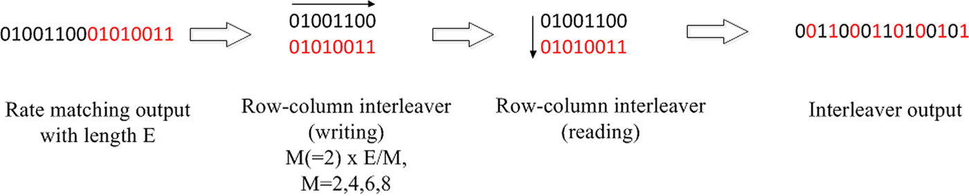
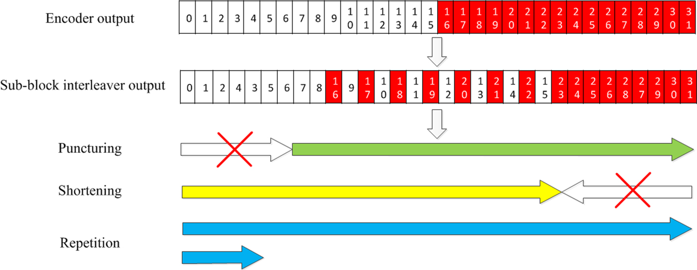
In 5G LDPC codes, further bit interleaving operation is applied after selection of the transmitted bits which is done by a row-column interleaver as described in Fig. 6 whose row size depends on the modulation order among 4/16/64/256 quadrature amplitude modulation (QAM). One of main motivations of this interleaver is to allocate information bits to better bit channel locations under Gray mapping which are most significant bits of each QAM symbol. Resource allocation type 1 in 5G supports interleaved mapping, which performs additional symbol-level interleaving, and it can be understood as the process of bit-interleaved coded modulation (BICM) [Reference Caire, Taricco and Biglieri27] combined with the bit-level interleaver.
Block interleaving operation of 5G LDPC codes.
III. 5G POLAR CODES
Let us consider length-N polar codes with code rate R; there are K=NR information bits. Encoding of 5G polar codes is done with a length-N encoder input binary sequence u for which values of N−K bit positions are fixed. For MBIOS channels, the value of such fixed positions which are called frozen bits is irrelevant in terms of performance, and hence, we will consider it to be zero-valued from now on. A length-N encoder output binary sequence x is generated as x = uG N = u(G 2)⊗n, where n = log 2 N, A ⊗n denotes n-th Kronecker power of matrix A, and  $G_2 = \left[\matrix{1 & 0 \cr 1 & 1}\right]$. Encoding of 5G polar codes can be graphically described as in Fig. 7 in which the leftmost side represents the encoder input and the rightmost side represents the encoder output. Note that the generator matrix G N of 5G polar codes is different from that given in [Reference ArÄśkan12]; the generator matrix in [Reference ArÄśkan12] is B N G N where B N is a bit-reversal permutation matrix. Due to bit-reversal invariance of G N [Reference ArÄśkan12, VII], this difference of generator matrix merely creates a permuted encoder output. Possible code lengths of 5G polar codes are 2n for 5 ≤ n ≤ 10 for uplink while 7 ≤ n ≤ 9 for downlink. polar codes are shown to achieve capacity of MBIOS channels using SC decoding [Reference ArÄśkan12], and the assumption of SC decoding typically strongly influences polar code design. Hence, let us briefly describe SC decoding as well as its enhanced version, SCL decoding, before discussing 5G polar code design in more detail.
Encoding of length-8 polar codes.
A) SC decoding of polar codes
Let us first consider SC decoding originally proposed in [Reference ArÄśkan12]. For each encoder input bit u i of length-N polar codes for 0 ≤ i < N, let us define a bit channel whose input is u i and output is  $y_0^{N-1},\, u_0^{i-1}$ with transition probability $W_N^{(i)}(y_0^{N-1},\, u_0^{i-1}\vert u_i)$ for observation $y_0^{N-1}$. In other words, there are N different bit channels for length-N polar codes. As described in [Reference ArÄśkan12], the main motivation of polar codes is a phenomenon called bit channel polarization in which the proportion of bit channels whose capacity approaches 1 becomes arbitrarily close to capacity of an underlying MBIOS channel while the capacity of remaining bit channels approach 0. Hence, a simple capacity achieving strategy (or a code) can be designed by transmitting information bits on those infinitely reliable bit channels.
A simple example of bit channel polarization under SC decoding can be illustrated as Fig. 8. At each kernel represented by G 2, u 0 is always less reliable than u 1, and sucha relationship can be utilized to identify that the reliability monotonically increases with respect to bit position index for a length-4 case. Longer polar codes are constructed by combining multiple shorter polar codes, and “bad” and “good” separation happens at every G 2 kernel starting from the rightmost side until reaching the leftmost side. Note that the resulting bit channel reliability order will not always be monotonic with respect to bit position index for polar codes longer than 4.
Bit channel polarization of length-4 polar codes.

The aforementioned concept of a bit channel is closely related to SC decoding. As a matter of fact,  $W_N^{(i)}(y_0^{N-1}, u_0^{i-1}\vert u_i)$ is a metric which an SC decoder uses to make decision on an information bit u i assuming that all previous decisions are correct or known. More rigorously, the following quantities (messages) are recursively computed for 0 < m ≤ log 2 N, 0 ≤ l < 2m−1 and 0 ≤ j < N/2m to identify $\hat {u}_i$ for 0 ≤ i < N. Below, the quantities $W_{2^m}^{(2l)}$ and $W_{2^m}^{(2l+1)}$ for m = log 2 N and 0 ≤ l < N/2 correspond to the aforementioned bit channel transition probability $W_N^i(y_0^{N-1},\, u_0^{i-1}\vert u_i)$ for 0 ≤ i < N.
 $$\eqalign{&W_{2^m}^{(2l)}\left(s_m^{(lN/2^{m-1}+j)}\right) \cr &\quad = \sum_{s_m^{\left(\displaystyle{lN \over 2^{m-1}}+j+\displaystyle{N \over 2^m} \right)}} \left\{ W_{2^{m-1}}^{(l)} \left(s_m^{\left(\displaystyle{lN \over 2^{m-1}}+j\right)} \oplus s_m^{\left(\displaystyle{lN \over 2^{m-1}}+j+\displaystyle{N \over 2^m} \right)} \right)\right. \cr &\left.\vphantom{\left\{ W_{2^{m-1}}^{(l)} \left(s_m^{\left(\displaystyle{lN \over 2^{m-1}}+j\right)} \oplus s_m^{\left(\displaystyle{lN \over 2^{m-1}}+j+\displaystyle{N \over 2^m} \right)} \right)\right.} \qquad \times W_{2^{m-1}}^{(l)} \left(s_m^{(lN/2^{m-1}+j+N/2^m )} \right) \right\},}$$
 $$\eqalign{& W_{2^m}^{(2l+1)} \left (s_m^{(lN/2^{m-1}+j+N/2^m ) } \right) \cr &\quad = W_{2^{m-1}}^{(l)} \left( \hat{s}_m^{(lN/2^{m-1}+j)}\oplus s_m^{(lN/2^{m-1}+j+N/2^m ) } \right) \cr & \qquad \times W_{2^{m-1}}^{(l)} \left(s_m^{(lN/2^{m-1}+j+N/2^m ) } \right),}$$
where
 $$s^b_a \in \{0, 1\},$$
 $$\hat{s}_{m-1}^{(lN/2^{m-1}+j)} = \hat{s}_m^{(lN/2^{m-1}+j)}\oplus \hat{s}_m^{(lN/2^{m-1}+j+N/2^m )},$$
 $$\hat{s}_{m-1}^{(lN/2^{m-1}+j+N/2^m ) }= \hat{s}_m^{(lN/2^{m-1}+j+N/2^m )},$$
 $$\eqalign{&\hat{s}_{\log_2N}^{(i)}= \left\{\matrix{\arg\max_{s_{\log_2N}^{(i)}} W_N^{(i)} (s_{\log_2N}^{(i)}) \hfill & {\rm for information} \hfill \cr 0 \hfill & {\rm for frozen}\hfill} \right. \cr & \qquad {\rm for } 0\leq i \lt N,}$$
 $$\eqalign{&W_1^{(0)} \left(s_1^{(j)}\oplus s_1^{(j+N/2) } \right)=W\left(y_j \left\vert s_1^{(j)}\oplus s_1^{(j+N/2)} \right. \right), \cr &W_1^{(0)} \left(s_1^{(j+N/2) } \right)= W \left(y_{j+N/2} \left\vert s_1^{(j+N/2)}\right. \right) \cr & \qquad {\rm for } 0\leq j \lt N/2,}$$
and W(y|x) corresponds to transition probability p Y|X (y|x) of an MBIOS channel. Note that  $\hat{s}_{\log_2N}^{(i)}$ above corresponds to $\hat{u}_i$.
The above quantities (messages) can be described by a diagram in Fig. 9 which demonstrates message generation trajectory for  $W_N^{(0)} (u_0 )$ of length-8 polar codes. In SC decoding, every bit channel is visited one by one in the monotonically increasing order with respect to i to evaluate $W_N^{(i)} (u_i)$ and decide $\hat {u}_i$. Note that the value of u i corresponding to frozen bits is known to the decoder. A similar procedure can be defined by using LLR of log (W(y i|x i = 0))/(W(y i|x i = 1)) as described in [Reference ArÄśkan12, VIII. A] instead of likelihood W(y i|x i).
Message flow of SC decoding.

Although polar codes achieve capacity of MBIOS channels using the SC decoder, its finite-length performance is noticeably worse than other typical channel coding schemes [Reference Tal and Vardy16]. SCL decoding [Reference Tal and Vardy16] can be considered to overcome this issue. As an example, consider SCL decoding with list size L=4 with length-8 polar codes, where u i with i = 0, 1, 2, 4 are frozen. The first information bit decoded is u 3, and the decoder computes  $W_N^{(3)} (u_3 )$ for that. However, instead of making decision on u 3, the decoder keeps both $\hat {u}_3=0,\, \hat {u}_3=1$, and computes subsequent messages under both hypotheses. While the decoder computes $W_N^{(5)} (u_5 )$ under both hypotheses to decode u 5, the decoder still does not make a decision on u 5, and keeps $(\hat {u}_3,\,\hat {u}_5 )=(0,\,0),\,(0,\,1),\,(1,\,0),\,(1,\,1)$. The decoder computes subsequent messages under all four hypotheses to reach $W_N^{(6)} (u_6 )$. Here, the decoder finally needs to make a decision. Since the number of hypotheses on $(\hat {u}_3,\,\hat {u}_5,\,\hat {u}_6 )$ is 8 which exceeds the list size, the decoder needs to select 4 out of 8 to continue. Such a selection is based on $W_N^{(6)} (u_6 )=P(y_0^{N-1},\,\hat {u}_0^5 \vert u_6) \propto P(y_0^{N-1}\vert \hat {u}_0^5,\,u_6)$ which essentially is the likelihood of each hypothesis; the decoder chooses 4 hypotheses whose $W_N^{(6)} (u_6 )$ are the largest. At the end of the decoding, a hypothesis (or a candidate) with the highest $W_N^{(N-1)} (u_{N-1} )$ is selected as the decoder output. By keeping the list, the SCL decoder tries not to make an early decision; note that a hard decision is still made for each bit of each candidate in the list, so decoding operation for eachcandidate in the list is conceptually the same as SC decoding. In other words, SCL decoding with the list size L would look computationally similar to running L times of SC decoding.
Since the 5G system is equipped with a CRC, performance of the aforementioned SCL decoding can be further improved by considering CA-SCL [Reference Tal and Vardy16]. Decoding operation under CA-SCL is identical to that under SCL until the final stage. The decoder output of CA-SCL is selected only among CRC-passing candidates. In other words, the decoder output can be from a candidate whose likelihood is not the largest. Such a procedure obviously improves block error rate (BLER), but also apparently degrades false alarm (FA); FA occurs when a CRC-passing codeword is not the actual transmitted one.
One of the main concerns with SC decoding is its latency issue mainly due to the fact that the information bits need to be decoded one by one. There are several practical solutions reducing latency of SC decoding [Reference Sarkis, Giard, Vardy, Thibeault and Gross17–Reference Fan19], and the main idea is to group the processing of multiple bits to expedite the decoding process. Unlike LDPC codes whose decoding is typically done on a graph representation of the parity check matrix as described in Fig. 1, the decoding of polar codes is typically done on a graph representation of the generator matrix as described in Fig. 9. This combined with the fact that the value of frozen bits is known to the decoder allows the decoder to efficiently skip processing of frozen bits during the decoding. The benefit of such skipped processing would be larger with lower code rate while control information for which polar codes are used is typically transmitted with lower code rate.
B) Information sequence
Design of the information sequence which can be thought as establishing the reliability order of bit channels is one of the most important aspects of polar code design. It can be done by evaluating Bhattacharyya parameters of bit channels [Reference ArÄśkan12, I.B.4)] assuming SC decoding.
Establishing the reliability order of bit channels can be efficiently done only for a limited set of channels such as BEC. For general channels like AWGN, density evolution (DE) can be applied to determine the reliability order as described in [Reference Mori and Tanaka13]. What DE does is to track the probability density function of intermediate LLR's during the decoding stages, and the main problem of such an approach is its prohibitively large computational complexity. Reduction of the computational load is investigated in [Reference Tal and Vardy14] by quantizing the space of the intermediate LLR's during SC decoding, but it is still computationally challenging. As a practical alternative, a precomputed information sequence may be stored, but the dependency of the reliability order on parameters like SNR, code length etc. makes application of the optimal sequences for all cases infeasible. As a compromise, 5G polar codes adopted a single information sequence and established a simple rule for determining information sequences of multiple different code lengths while maintaining good enough performance.
One aspect which can be useful in designing the information sequence for a practical system is the concept of universal partial order (UPO). While the reliability order of bit channels depends on the communication channel, it can be shown that there is a universal partial order in bit channels which holds for any MBIOS channel [Reference Schurch28]. There are two things which need to be considered to understand the general trend of bit channel reliability, which are row weight of a generator matrix and the order of decoding. It is worth noting that polar codes and Reed-Muller (RM) codes share the same generator matrix, and the information sequence selection rule is what only differentiates them. For RM codes, the information sequence is determined based on row weight of the generator matrix; bits with higher row weight are selected as information. This choice of the information sequence is understandable since row weight indicates the amount of protection by coding. Even for polar codes, such row weight has a strong influence to bit channel reliability. Also, the order of decoding under SC decoding strongly affects bit channel reliability, i.e., bits decoded later tend to be more reliable. This is due to the fact that undecoded later-positioned bits (including later-positioned frozen bits!) act as uncertainty when a decoding attempt is made for earlier-positioned bits. For length-4 polar codes, row weights corresponding to bit positions 0/1/2/3 are 1/2/2/4. It is reasonable to assume that bit position 3 is more reliable than bit positions 1 or 2, and bit positions 1 or 2 are more reliable than bit position 0 based on row weight. It is also reasonable to assume that bit position 2 is more reliable than bit position 1 since bit position 2 is decoded later in SC decoding. Note that these assumptions match with the UPO of length-4 polar codes [Reference He29]. Note that an extended partial order in addition to the UPO can be established if we restrict the channel to be AWGN [Reference He29].
The information sequence of 5G polar codes mostly satisfies the UPO. Note that SCL decoding was assumed for the design of the 5G information sequence, and the UPO based on SC decoding does not necessarily need to be satisfied for all bit positions for better performance in this case [Reference Hashemi, Mondelli, Hassani, Urbanke and Gross30]. The final information sequence design of 5G polar codes was done by extensive performance simulation on an AWGN channel, and the information sequence is described in Table 5.3.1.2-1 of [22]. It is described with respect to the length 1024, and the information sequence of shorter polar codes can be obtained by simply ignoring values larger than or equal to the code length, i.e., the information sequences of 5G polar codes of different lengths are nested, which is one of the main design targets of 5G polar codes.
C) Distributed CRC
Large latency is one of the main concerns of SC decoding. To alleviate this, 5G polar codes adopted distributed (D) CRC. Instead of attaching CRC bits at the end of the information bits, the CRC bits are distributed within the information bits while ensuring that every CRC bit only has a dependency on the information bits occurring earlier than that. For example, let us consider a CRC polynomial g(x) = x 4 + x + 1 whose generator matrix has the form [I P] where P is given below for the information length of 10.
 $$P = \left[\matrix{1 & 1 & 0 & 1 \cr 1& 1 & 1 & 1 \cr 1 & 1 & 1 & 0 \cr 0 & 1 & 1 & 1 \cr 1 & 0 & 1 & 0 \cr 0 & 1& 0 & 1 \cr 1 & 0 & 1 & 1 \cr 1 & 1 & 0 & 0 \cr 0 & 1 & 1 & 0 \cr 0 & 0 & 1 & 1}\right]$$
Dependency of the ith CRC bit on the information bits is given by nonzero rows of the ith column of P. For example, the first CRC bit hasa dependency on 6 information bits. As is, the first CRC bit can only appear after the last information bit contributing to it, which is the eighth information bit. However, we can also consider interleaving of the information bits such that those 6 information bits appear the earliest as described in Fig. 10. In this way, the CRC bits from any CRC polynomial can be distributed. One thing to note is that such CRC and information bit interleaving pattern can depend on information length. However, if the interleaving pattern is designed for the longest information length, then the interleaving pattern of shorter lengths can be obtained by appropriately considering null elements from the longer pattern. 5G polar codes also adopted this approach and null elements shown in Fig. 10 correspond to it.
Illustration of D-CRC for K = 10, K = 8 and g(x) = x 4 + x + 1.
Let us consider now how the D-CRC can be utilized to reduce the latency of SC decoding. Since a whole code block is considered to be erroneous if any CRC check bit fails, the decoder can check each CRC bit as soon as it is encountered during SC decoding and terminates the decoding if any such check fails. This can especially be beneficial for physical downlink control channel (PDCCH) processing for which polar codes are used since it involvesa considerable amount of blind decoding attempts within a configured search space while only a few candidates are typically valid. Note that the aforementioned early termination can only happen if all candidates in the list fail under SCL decoding.
D) Rate matching and interleaving
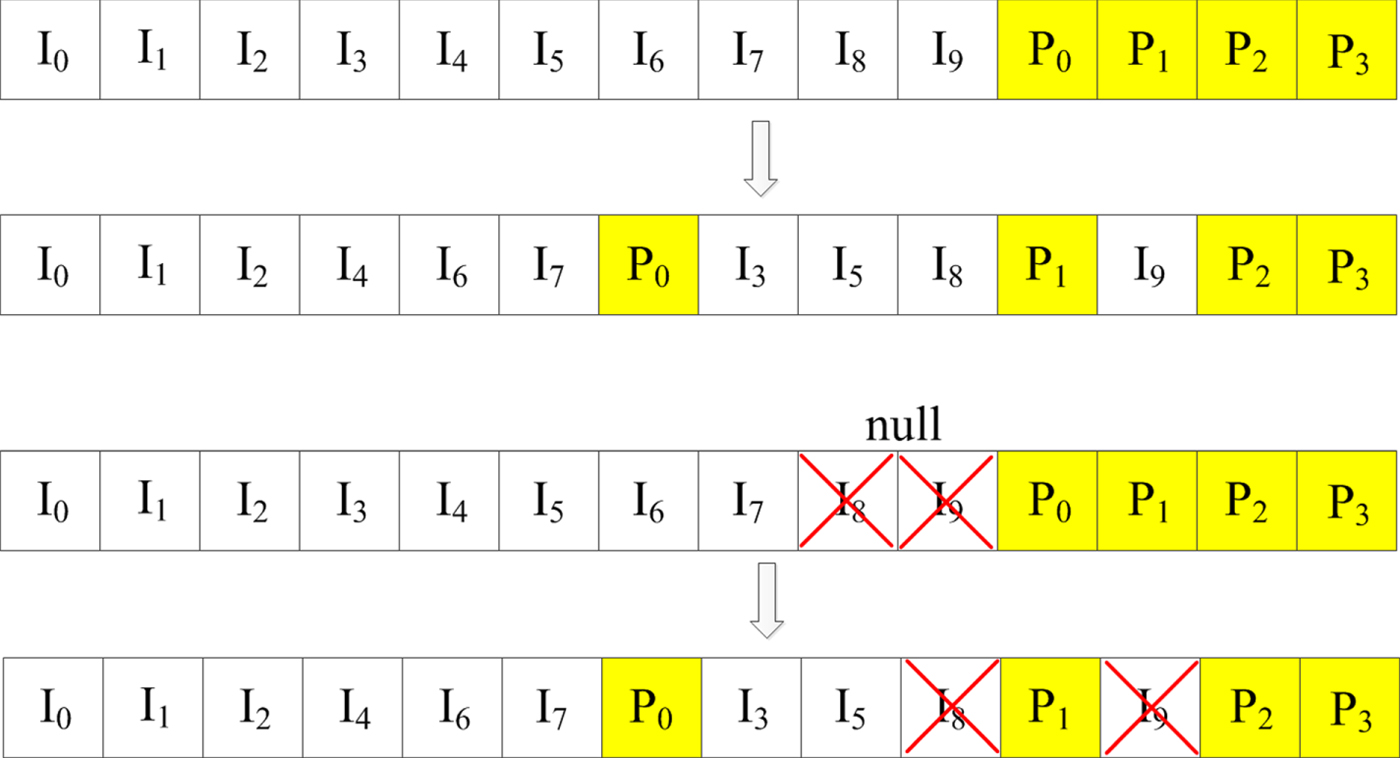
5G polar codes need to support rate matching functionality to select arbitrary amount of transmitted bits from the mother coded output. In this sub-section, we describe the rate matching scheme adopted for 5G polar codes in detail. Fig. 11 describes the interleaving and rate matching procedure of 5G polar codes, and each component in the diagram will be explained throughout this sub-section.
Interleaving and rate matching procedure of 5G polar codes.
1) Interleaving
5G polar codes uses a sub-block inter-leaver. As described in Fig. 11, the encoded output is divided into 32 equal-length sub-blocks that are interleaved. The rate matching is applied to this interleaved version of the encoded output, and the rate matching output is mapped to QAM symbols. For the uplink, there is one more triangular interleaver applied to the rate matching output before QAM-symbol mapping.
2) Puncturing
Puncturing is a typical way of applying the rate matching. In puncturing, the mother code length N is longer than the rate matching output size E, and some coded outputs are not transmitted to meet the rate matching output size. One can view puncturing scheme as the way how non-transmitted positions are selected. In 5G polar codes, the first N−E bits of the interleaved output are punctured as described in Fig. 11. Note that such selection of the punctured bit positions is not systematically justifiable since better performance may be achieved if the punctured locations are carefully chosen [Reference El-Khamy, Lin, Lee and Kang31]. Simply speaking, similar to the information sequence design, bit channel reliability with each different puncturing pattern would need to be evaluated to find a good puncturing pattern. However, due to likely dependency of a puncturing pattern on code length, information length, and SNR etc, such a good scheme may actually perform worse than other simpler schemes unless puncturing pattern can be designed for each specific case, which is not easily feasible in practice. In this sense, puncturing scheme adopted for 5G polar codes can be considered as a practical compromise.
Note that puncturing of the encoder output bits creates bit channels with zero reliability which must be frozen. Fig. 12(a) describes such a phenomenon using length-8 polar codes with block puncturing similar to the scheme of 5G polar codes; for simplicity, we assume no interleaving before puncturing. If x 0 is punctured, then u 0 cannot be decoded since u 0 is only carried by x 0. Similarly, if x 0 and x 1 are punctured, then u 0 and u 1 are not decodable. In 5G polar codes, input bit indices corresponding to the punctured output indices (before the sub-block interleaving described in Fig. 11) are frozen, and this simple rule satisfies the aforementioned zero-reliability position avoidance.
Block rate matching schemes for polar codes. (a) Block puncturing, (b) Block shortening.
3) Shortening
At the encoder output, shortening [Reference Wang and Liu32] shares the same principle of puncturing in a sense that only a part of the output positions is selected to be transmitted. As described in Fig. 11, the main difference between puncturing and shortening at the encoder output is that puncturing is applied from the start of the interleaved encoder output while shortening is applied from the end. Similar to puncturing, the input bit indices corresponding to the shortened output indices (before sub-block interleaving described in Fig. 11) are frozen. However, the reason why such bit positions are frozen is quite different from that of puncturing, and it can be explained by Fig. 12(b) which describes the encoding of length-8 polar codes with block shortening similar to the scheme of 5G polar codes; for simplicity, we assume no interleaving before rate matching. Consider three punctured output bits x 5, x 6, x 7 by shortening. It can be seen that these three output bits only depend on three input bits u 5, u 6, u 7 whose indices are the same as the shortened output bits. In other words, if those three input bits are frozen, then values of three shortened output bits are known. Hence, although those three shortened output bits are not transmitted, the decoder can assume that they were transmitted through an infinitely reliable channel. As mentioned earlier, undecoded later-positioned bits act as uncertainty in SC decoding, and such infinite reliability of the later-positioned bits can reduce the uncertainty.
To reduce the amount of frozen bits due to shortening, it would be desirable to shorten later output bit positions since the later output positions tend to depend on smaller number of input bits, e.g., x 7 = u 7. However, the later input bit positions which are frozen under such shortening are generally considered as most reliable. In other words, it sacrifices reliable positions as frozen bits to improve earlier bit decoding performance. In puncturing, the reliable positions are still used as information bits, but puncturing of output bits createsa loss in observation which degrades overall bit channel reliability. In 5G polar codes, shortening is applied for higher code rates while puncturing is applied for lower code rates.
4) Repetition
Repetition is another typical rate matching scheme when the rate matching output size is larger than the mother code length. In 5G polar codes, repetition is applied at the interleaved output as described in Fig. 11. Since 5G polar codes utilize multiple different mother code lengths as mentioned earlier, the choice of rate matching scheme is not straightforward; either puncturing/shortening or repetition can be applied given the rate matching output size and depending on which mother code length is used. In 5G polar codes, puncturing/shortening is favored. In other words, given the rate matching output size, repetition is selected if the rate matching output size is sufficiently close to the mother code length smaller than it and if the code rate, i.e., the number of information bits divided by the rate matching size, is not too high.
IV. PERFORMANCE
In this section, we briefly describe performance of 5G LDPC and polar codes. Fig. 13 describes the performance of 5G LDPC codes in the AWGN channel. A code block size of 8448 which is the maximum size in 5G standards was used for simulation. Modulation orders of 4/16/64/256 QAM were simulated. Sum-product algorithm [Reference Kschischang, Frey and Loeliger33] was utilized as the decoding algorithm. Note that, for each code rate, required SNR for the same block error rate (BLER) monotonically increases as the modulation order increases. For each modulation order, the required SNR monotonically increases as the code rate increases as expected. Performance trend is also well ordered with respect to relative throughput, i.e., the number of bits per modulation order times the code rate.; the required SNR increases as the relative throughput increases.
5G LDPC codes performance in the AWGN channel for various code rates and modulation orders.
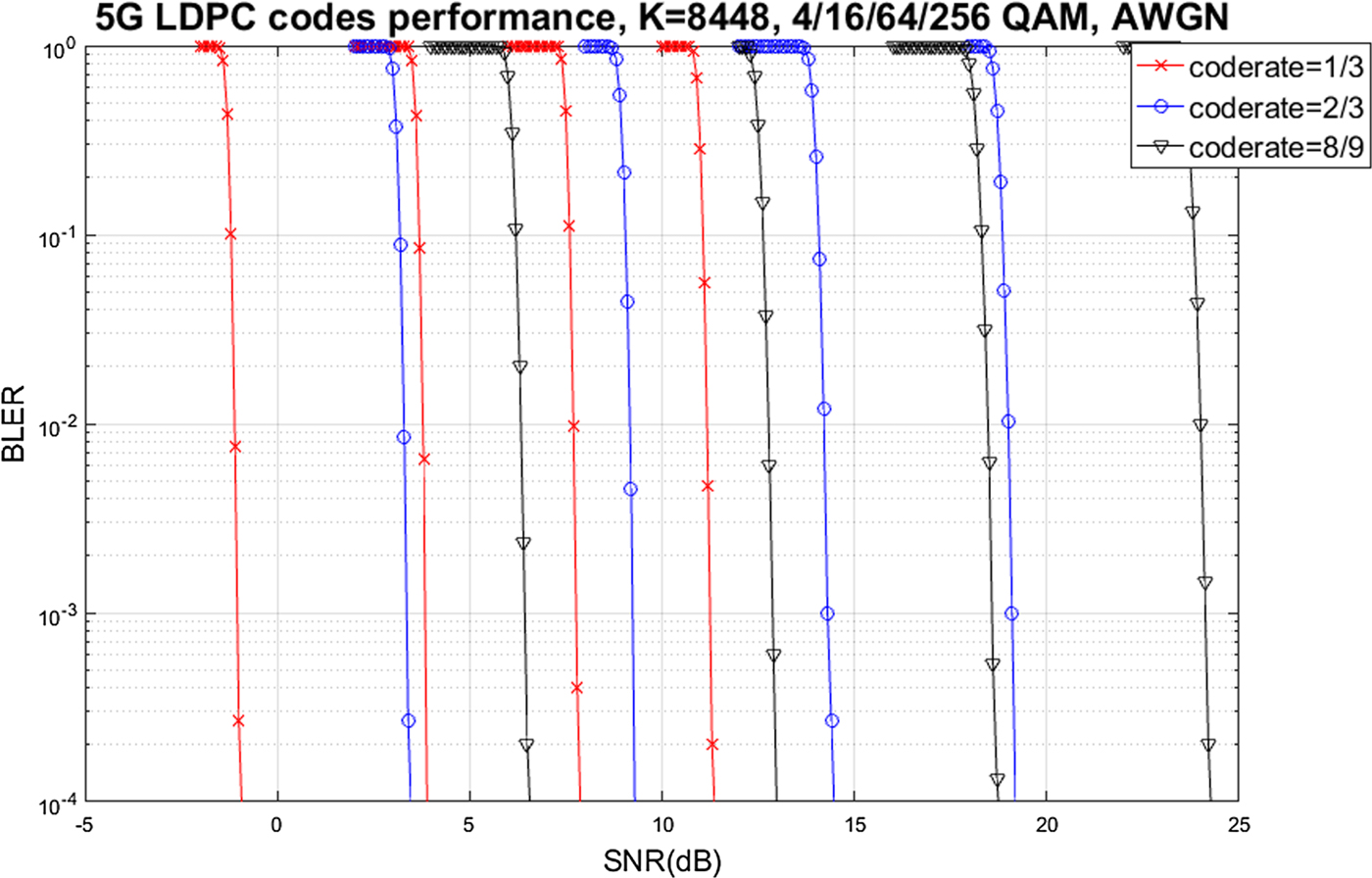
Figure 14 describes performance of 5G polar codes on AWGN channel. Code lengths of 128/256/512 were simulated, and no rate matching was applied, i.e., the transmitted length is the same as the code length. The simulated information size was between 70 and 80 which is the range of typical downlink control information size (plus 24-bit CRC) transmitted via PDCCH in 5G standards. 4QAM which is the modulation order of the PDCCH was used for simulation. SCL decoding with list size 8 is utilized as the decoding algorithm. Note that, for each code length, required SNR monotonically increases as the information size increases. As expected, given the information size, the required SNR monotonically increases as the code length decreases.
5G polar codes performance in the AWGN channel for various information size K and code length N.

V. CONCLUSION
LDPC codes and polar codes have been shown in the literature to be asymptotically optimal for MBIOS channels. For both codes, however, practical issues of finite-length code performance, complexity, and latency had to be examined closely in order to be adopted for 5G.
In the case of LDPC codes, its practical applicability was partially demonstrated by its adoption to IEEE 802.11 standards that have seen widely successful commercial deployments. While the use of QC-LDPC codes and IRA structure are similar to IEEE 802.11 design, the base graph and circular-shift values, as well as the support of rate matching and IR-HARQ, are unique features of 5G LDPC codes that account for high throughput and reliability requirements.
For polar codes, design of the information sequence that has a good complexity-performance trade-off was one of the main focuses. Support of rate matching utilizing puncturing, shortening, and repetition was another important design aspect. For practical applicability, latency and finite-length code performance are also important considerations. The latency of decoding is reduced by the use of distributed CRC, and the finite-length code performance improvement can be addressed by the use of an advanced decoder such as the CRC-aided successive cancellation list decoder.
STATEMENT OF INTEREST
None.
Jung Hyun Bae is a Principal Engineer at Samsung SoC Lab in San Diego, CA, in charge of channel coding algorithm development for cellular modem. He received his Ph.D. degree in Electrical Engineering from University of Michigan, Ann Arbor in 2011. Since 2011, he has been with Samsung USA, developing physical layer algorithms of channel estimation and tracking, MIMO detection and channel decoding for cellular modems and Wi-Fi.
Ahmed Abotabl received the B.S. degree (Hons.) from Alexandria University, Egypt, the M.Sc. degree from Nile University, Egypt, and the Ph.D. degree from the University of Texas at Dallas, Richardson, TX, USA, all in electrical engineering. He is currently a Senior Engineer at Samsung SoC Lab in San Diego, CA. His research interests include information theory, coding theory and their applications in physical layer security, and machine learning. He received the UTD Electrical Engineering Industrial Advisory Board Award in 2016 and the Louis-Beecherl Jr. Award in 2015 from the University of Texas at Dallas.
Hsien-Ping Lin received the B.S. degree from National Chiao Tung University, Hsinchu, Taiwan, in 2008 and Ph.D degree in electrical and computer engineering from University of California, Davis, in 2016. Since 2017, he has been with Samsung SoC Lab in San Diego, CA, developing physical layer algorithms of channel decoding on 5G NR modem.
Kee-Bong Song received his B.S degree of EECS from Korea Advanced Institute of Science and Technology (KAIST) in 2000 and M.S. and Ph.D. degrees in EE from Stanford University in 2002 and 2005, respectively. He is currently a vice president and the cellular group leader in SOC Lab in Samsung Semiconductor Inc., conducting the cellular modem systems R&D and supporting commercialization of Samsung's Shannon modem/Exynos ModAP products for USA/Canada/Latin America operators. Prior to Samsung, he was with Apple, Amicus Wireless Technology and Qualcomm working on various projects on wireless technologies.
Jungwon Lee is a Vice President at Samsung SoC Lab in San Diego, CA, in charge of cellular modem and multimedia. He received his Ph.D. degree in Electrical Engineering from Stanford University in 2005. From 2003 to 2010, he was with Marvell Semiconductor, Inc., where he developed HD Radio, Bluetooth, Wi-Fi, WiMAX, and LTE chips. Since 2010, he has been with Samsung USA, developing communication chips such as cellular modems, Wi-Fi, Bluetooth, ZigBee, and GNSS and multimedia solutions. He is currently conducting research on 5G NR modem and AI. He has co-authored more than 100 papers and holds over 250 US patents. Dr. Lee is an IEEE Fellow.


 Open access