





1 Introduction
In high-power laser systems, optical components are prone to laser-induced damage (LID) under intense irradiation, limiting the maximum achievable output energy[ Reference Li, Lu, Xie, Sun, Liang, Yang, Guo, Zhu, Zhang, Zhang, Xue, Zhang, Haq, Zhu, Kang and Zhu 1 , Reference Jiao, Shao, Zhao, Wu, Ji, Wang, Xia, Liu, Zhou, Ju, Cai, Ye, Qiao, Hua, Li, Pan, Ren, Sun, Zhu and Lin 2 ]. A common solution is to enlarge the optical aperture to reduce the optical fluence and improve damage resistance. However, larger apertures lead to heavier structural loads. In addition, high energy density often involves more laser beams, requiring adjustment mechanisms to support compact array configurations. Furthermore, beam paths extending hundreds of meters impose stricter demands on the alignment accuracy of optical elements.
To address the above challenges in high-power laser systems, extensive research has been conducted on adjustment mechanisms, with related technologies implemented in systems such as OMEGA-EP, PETAL, NIF and SG-II[ Reference Blanchot, Bar, Behar, Bellet, Bigourd, Boubault, Chappuis, Coic, Damiens-Dupont, Flour, Hartmann, Hilsz, Hugonnot, Lavastre, Luce, Mazataud, Neauport, Noailles, Remy, Sautarel, Sautet and Rouyer 3 – Reference Hein, Hornung, Bödefeld, Podleska, Sävert, Wachs, Kessler, Keppler, Wolf, Polz, Jäckel, Nicolai, Schnepp, Körner, Kaluza and Paulus 8 ], including those incorporating compliant mechanisms. Owing to their high precision, frictionless motion and zero-clearance characteristics, compliant mechanisms are widely employed in precision applications such as micro-positioning and optical alignment[ Reference Ling, Cao, Howell and Zeng 9 ]. Accordingly, a variety of compliant modeling methods have been extensively developed. At present, small-deflection modeling of compliant mechanisms generally falls into four categories[ Reference Ling, Howell, Cao and Chen 10 ]: (1) Castigliano’s second theorem, based on strain energy and the first derivative relationship between input and output displacements[ Reference Arredondo-Soto, Cuan-Urquizo and Gomez-Espinosa 11 – Reference Lobontiu and Garcia 13 ]; (2) elastic beam theory, based on the relationship between load and work[ Reference Ling, Cao, Zeng, Lin and Inman 14 , Reference Ni, Deng, Wu, Li and Li 15 ]; (3) the compliance matrix method, involving coordinate transformations and matrix compositions[ Reference Liang, Zhang, Chi, Song, Ge and Ge 16 – Reference Dong, Chen, Gao, Yang, Sun, Du, Tang and Zhang 18 ]; and (4) the finite element method (FEM). To reduce modeling complexity, Howell and Midha[ Reference Howell and Midha 19 ] and Midha et al. [ Reference Midha, Bapat, Mavanthoor and Chinta 20 ] introduced the pseudo-rigid-body model (PRBM), which approximates flexible members using a combination of rigid links and torsional springs. In addition, energy-based methods based on potential energy minimization[ Reference Wu, Shao, Su and Fu 21 , Reference Wu, Shao and Fu 22 ], and hybrid modeling frameworks combining analytical expressions with numerical integration[ Reference Ling, Cao, Howell and Zeng 9 , Reference Ling, Cao, Jiang and Lin 23 , Reference Ling, Howell, Cao and Jiang 24 ], have been proposed to improve modeling efficiency, accuracy and adaptability. These methods are typically applied to compliant mechanisms at the millimeter or centimeter scale under light to moderate loading, where deformations remain small. However, they often neglect parasitic displacements caused by rigid-body rotations, parallel coupling and motion interdependencies. In high-power laser systems, large-scale adjustment structures typically employ meter-scale frames with local compliance and global rigidity to support optical elements. Even minor deflections in such systems can induce millimeter-scale parasitic displacements, which nonlinearly affect the posture and hinder meeting microradian-level alignment precision. Although models such as the chained beam-constraint approach[ Reference Ma and Chen 25 , Reference Awtar and Sen 26 ], nonlinear finite element analysis[ Reference Sen and Awtar 27 ] and elliptic integral solutions[ Reference Wang and Xu 28 ] can account for parasitic displacements, their high-order nonlinear formulations result in low computational efficiency and limited applicability to error modeling and calibration in complex spatial mechanisms.
Kinematic calibration primarily consists of error modeling, identification and compensation[ Reference Luo, Xie, Liu and Xie 29 ]. However, structural clearances at rigid joints are often challenging to observe directly. One approach is to model the clearances equivalently as dual spring-damper systems and derive the corresponding mechanical transmission relationships[ Reference Zhang and Zhang 30 , Reference Tian, Zhang, Chen and Yang 31 ], or to characterize them using probabilistic distributions[ Reference Zeng, Qiu, Zhang and Zhang 32 ], with extensions to more complex three-dimensional analyses[ Reference Yan, Xiang and Zhang 33 , Reference Xin, Zhu, Meng and Jiang 34 ]. Subsequently, kinematic models are established based on screw theory, using the product of exponentials (PoE) formulation[ Reference Wu, Liang, Zhang, Kong, Wang and Chen 35 ], transformation matrices or vector methods[ Reference Zeng, Qiu, Zhang and Zhang 32 , Reference Chen, Zhang, Huang, Wu and Ota 36 ] to relate joint clearances to end-effector poses. For rigid joint clearances in compliant mechanisms, force equilibrium equations can be derived by incorporating PRBMs[ Reference Erkaya, Dogan and Sefkatlioglu 37 , Reference Erkaya, Dogan and Ulus 38 ]. Most existing studies focus on two-dimensional joint clearance modeling, whereas research on clearance error compensation in compliant spatial mechanisms remains limited, underscoring the need to advance this area to further enhance system accuracy.
Error identification and compensation are fundamentally optimization processes aimed at minimizing system-level errors. For simple systems, finite element simulations can be directly applied; for more complex systems, geometric errors and compliance parameters are often linearized to construct Jacobian matrices, which are then solved using least-squares methods[ Reference Ecorchard, Neugebauer and Maurine 39 ]. However, these approaches encounter significant limitations when applied to nonlinear or high-dimensional parameter problems. To improve accuracy and convergence, various enhanced methods have been proposed, including hybrid algorithms that combine the Levenberg–Marquardt algorithm with adaptive differential evolution[ Reference Zeng, Qiu, Zhang and Zhang 32 ], particle swarm optimization (PSO) based on measured trajectories[ Reference He, Chen, Liang, Zhang and Chen 40 ], hybrid genetic algorithms with enhanced robustness[ Reference Sun, Lian, Zhang and Song 41 ] and calibration techniques that integrate extended Kalman filters with adjoint error models[ Reference Lin, Ding and Zhu 42 ].
In summary, current modeling and error compensation methods for compliant mechanisms remain limited in addressing complex structural gaps and nonlinear multi-parameter optimization problems. In addition, black-box approaches often lack theoretical interpretability regarding error mechanisms. This study investigates a meter-scale heavy-load parallel adjustment structure that integrates rigid and compliant components, and proposes a kinetostatic modeling and error calibration approach based on an improved PSO algorithm. The proposed approach integrates compliance matrix methods with energy-based modeling to derive the strain energy expression of the compliant mechanism. A PRBM is introduced to incorporate both parasitic motions and clearance effects within a unified modeling framework. Furthermore, an equivalent structural gap model is proposed to systematically capture nonlinear system errors, including elastic deformation and backlash in key components such as ball screws and flexible couplings. These sliding behaviors and their impact on posture adjustment accuracy are incorporated into a unified error model. The model enables simultaneous nonlinear coupling among input displacement, output displacement and external loads, and adaptively switches between contact and clearance-slipping states of the mechanism. This enables the unified modeling of rigid, compliant and clearance characteristics. For error identification, global sensitivity indices are employed to identify key parameters and enhance model specificity. In addition, a global–dynamic multi-subgroup cooperative PSO algorithm is developed, incorporating subgroup division, regional updates and isolation strategies. This approach balances local refinement with broad global exploration, enhancing the convergence stability and identification accuracy of high-dimensional nonlinear error models.
The remainder of this paper is structured as follows. Section 2 describes the architecture of the compliant parallel adjustment mechanism designed for meter-scale large-aperture gratings. It elaborates on the construction and integration of the ideal kinetostatic model, the parasitic motion model and the equivalent structural gap representation. Section 3 conducts global sensitivity analysis to identify the most influential error sources and introduces the global–dynamic multi-subgroup cooperative PSO algorithm along with its implementation process. Simulation results are presented to verify the feasibility of the proposed approach. Section 4 reports prototype experiments that validate the effectiveness of the error model and its calibration strategy. Finally, Section 5 summarizes the entire study.
2 Kinetostatic analysis and error modeling of compliant mechanisms
2.1 Kinetostatic modeling of compliant mechanisms
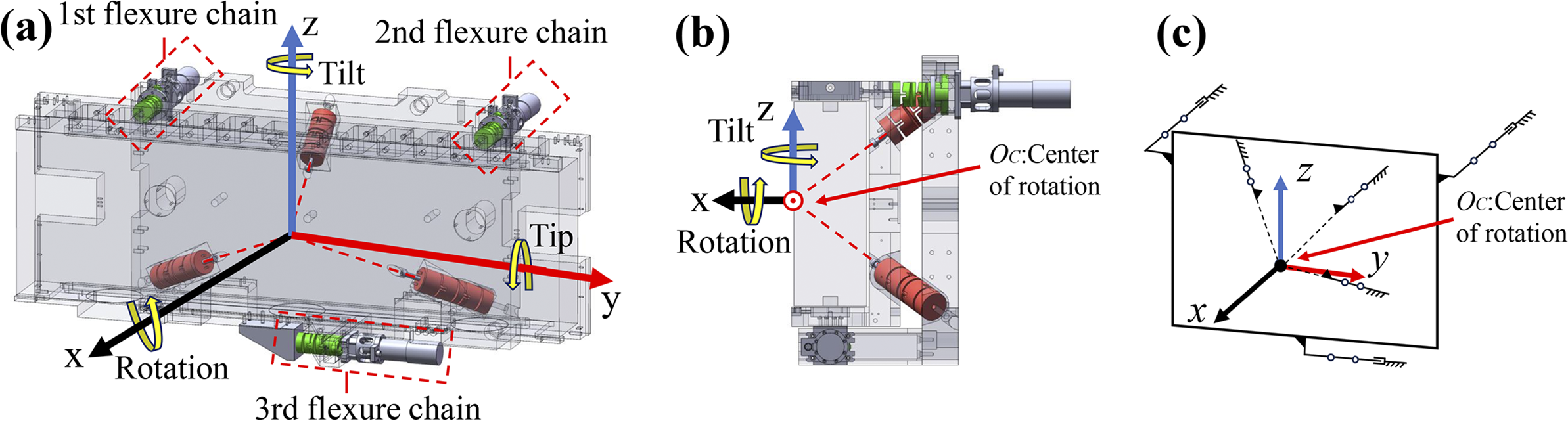
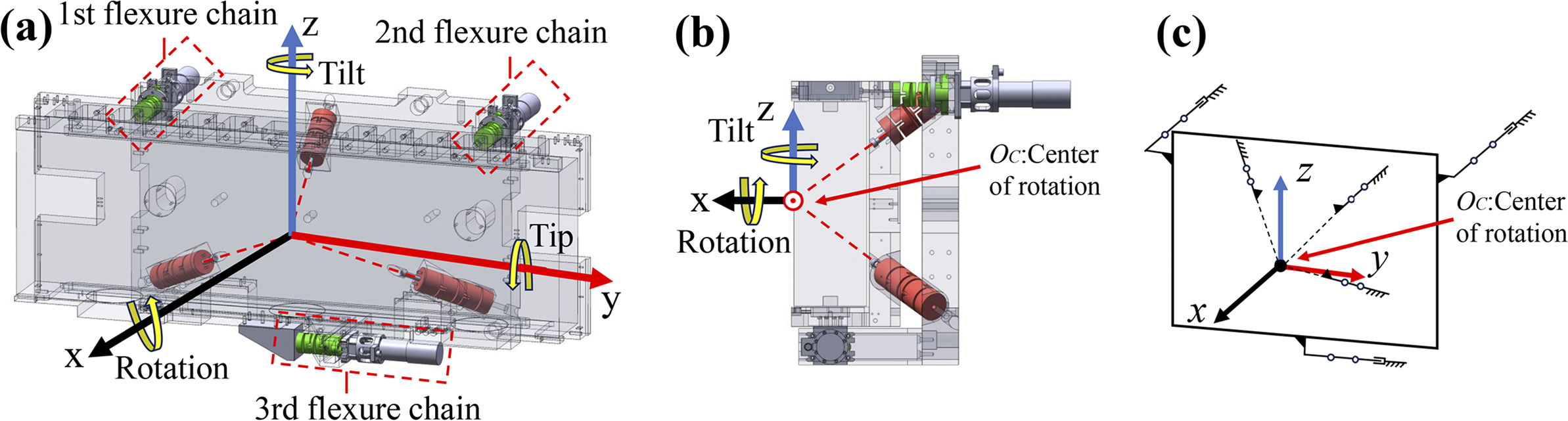
A device capable of supporting heavy loads and accommodating constrained spatial array configurations is shown in Figure 1. The mechanism consists of a far-center spherical joint formed by three flexure chains arranged in a triangular pyramid configuration, which provides a remote instantaneous center of rotation at their intersection and bears the system load. Two driving chains are symmetrically positioned on either side to control tip and tilt, while a third transverse driving chain, orthogonal to the others, is used to constrain or adjust the rotational degree of freedom.
Configuration of the remote-center compliance mechanism: (a) structural model; (b) side view; (c) schematic diagram of the mechanism.
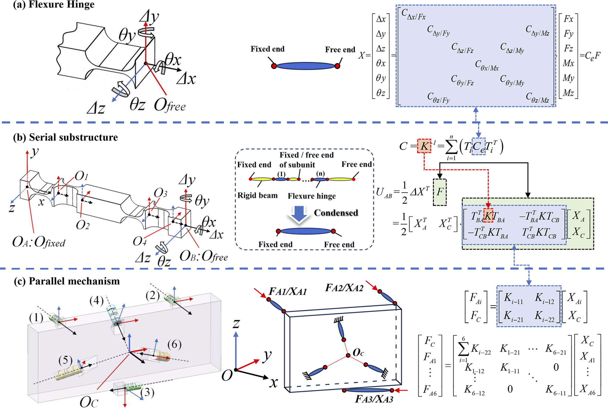
As shown in Figures 2(a) and 2(b), the compliance mapping between a flexible chain and a single flexure element is established based on the right-hand rotation convention and the derivation by Chen et al.
[
Reference Chen, Liu and Du
43
]. Subsequently, the flexible chains are combined in parallel, and the elastic strain energy U
AB is expressed as a function of the relative displacement ${\Delta}$
X
between ends O
A and O
B:
${\Delta}$
X
between ends O
A and O
B:
 $$\begin{align}\boldsymbol{C}={\boldsymbol{K}}^{-1}=\sum \limits_{i=1}^n\left({\boldsymbol{T}}_i{\boldsymbol{C}}_{\mathrm{e}}{\boldsymbol{T}}_i^{\mathrm{T}}\right),\end{align}$$
 $$\begin{align} {U}_{\mathrm{A}\mathrm{B}}=\frac{1}{2}\Delta {\boldsymbol{X}}^{\mathrm{T}}\boldsymbol{F}=\frac{1}{2}{\left({\boldsymbol{T}}_{\mathrm{C}\mathrm{B}}{\boldsymbol{X}}_{\mathrm{C}}-{\boldsymbol{T}}_{\mathrm{BA}}{\boldsymbol{X}}_{\mathrm{A}}\right)}^{\mathrm{T}}\boldsymbol{K}\left({\boldsymbol{T}}_{\mathrm{C}\mathrm{B}}{\boldsymbol{X}}_{\mathrm{C}}-{\boldsymbol{T}}_{\mathrm{BA}}{\boldsymbol{X}}_{\mathrm{A}}\right),\end{align}$$
Simplification and combination process of the remote-center compliance mechanism and its topological structure: (a) flexible hinge; (b) series substructure; (c) parallel substructure and coordinate system. Here,
θ
, $\boldsymbol{\Delta}$
,
F
and
M
denote the angle, displacement, force and moment, respectively (e.g.,
$\boldsymbol{\Delta}$
,
F
and
M
denote the angle, displacement, force and moment, respectively (e.g., $\boldsymbol{\Delta}$
includes Δx, Δy and Δz);
C
indicates directional compliance, for example C
Δx/Fx
for axial compliance.
$\boldsymbol{\Delta}$
includes Δx, Δy and Δz);
C
indicates directional compliance, for example C
Δx/Fx
for axial compliance.
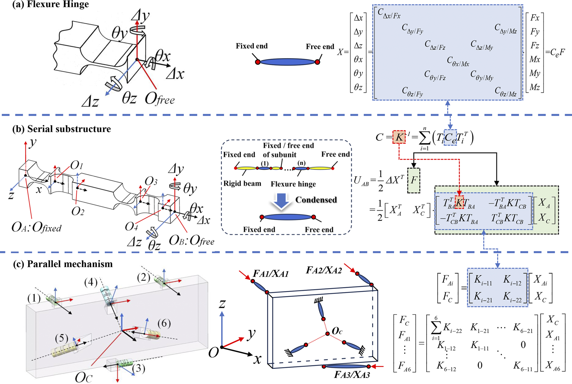
where C e denotes the compliance matrix of the flexure hinge; C and K represent the compliance and stiffness matrices of each flexure chain, respectively; n is the number of flexural elements in each chain; and T i is the transformation matrix. Since each flexure chain is rigidly connected to the grating frame, the pose variation at the connection point O B can be indirectly represented via the center point O C. X C and X A represent the pose of the front-center point O C of the grating and the pose of the actuation endpoint O A of the flexure chain, respectively. Here, T BA and T CB are the corresponding position transformation matrices.
By combining Figure 2(c) with Equations (1) and (2), the overall force–displacement relationship of the mechanism is obtained:
 $$\begin{align}\left[\begin{array}{@{\ }c@{\ }}{\boldsymbol{F}}_{\mathrm{C}}\\ {}{\boldsymbol{F}}_{\mathrm{A}1}\\ {}\vdots \\ {}{\boldsymbol{F}}_{\mathrm{A}6}\end{array}\right]=\left[\begin{array}{cccc}\sum \limits_{i=1}^6{\boldsymbol{K}}_{i-22}& {\boldsymbol{K}}_{1-21}& \dots & {\boldsymbol{K}}_{6-21}\\ {}{\boldsymbol{K}}_{1-12}& {\boldsymbol{K}}_{1-11}& \cdots & 0\\ {}\vdots & \vdots & & \vdots \\ {}{\boldsymbol{K}}_{6-12}& 0& \cdots & {\boldsymbol{K}}_{6-11}\end{array}\right]\left[\begin{array}{@{\ }c@{\ }}{\boldsymbol{X}}_{\mathrm{C}}\\ {}{\boldsymbol{X}}_{\mathrm{A}1}\\ {}\vdots \\ {}{\boldsymbol{X}}_{\mathrm{A}6}\end{array}\right],\end{align}$$
where F Ai and X Ai represent the force and displacement at the driving (or fixed) end of the ith flexure chain, respectively. According to the principle of force translation, the weight of the adjustment mechanism and the grating can be equivalently transferred to the front-center point O C of the grating (hereafter referred to as center point O C), and the resulting equivalent load is denoted by F C . Here, X C represents the position and orientation of point O C, while K i−jk denotes the 6×6 block stiffness matrix located at the jth row and kth column of the ith flexure chain, as shown in the formulation of Figure 2(c).
2.2 Flexure parameters and positional error modeling
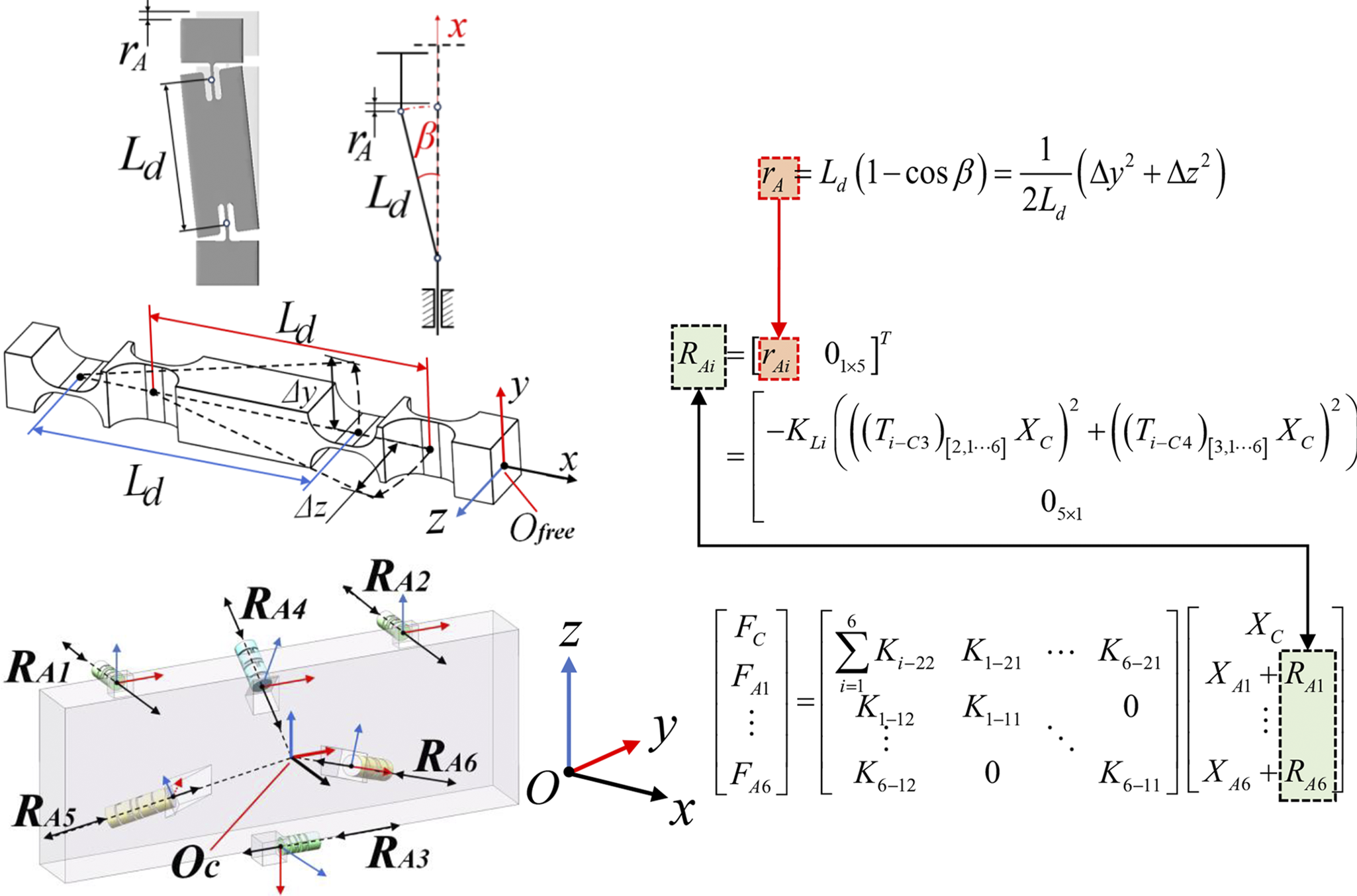
As the motion range and structural dimensions increase, axial parasitic displacements resulting from rigid-body rotation induced by flexure hinge deformation become non-negligible, as illustrated in Figure 3. Based on Taylor series expansion, the axial deformation displacement r A can be expressed as follows:
 $$\begin{align}{r}_\mathrm{A}={L}_\mathrm{d}\left(1-\cos \beta \right)=\frac{\Delta {y}^2+\Delta {z}^2}{2{L}_\mathrm{d}}={K}_\mathrm{Li}\left(\Delta {y}^2+\Delta {z}^2\right),\end{align}$$
Schematic and theoretical relationship of axial displacement caused by deformation of the flexible chain.
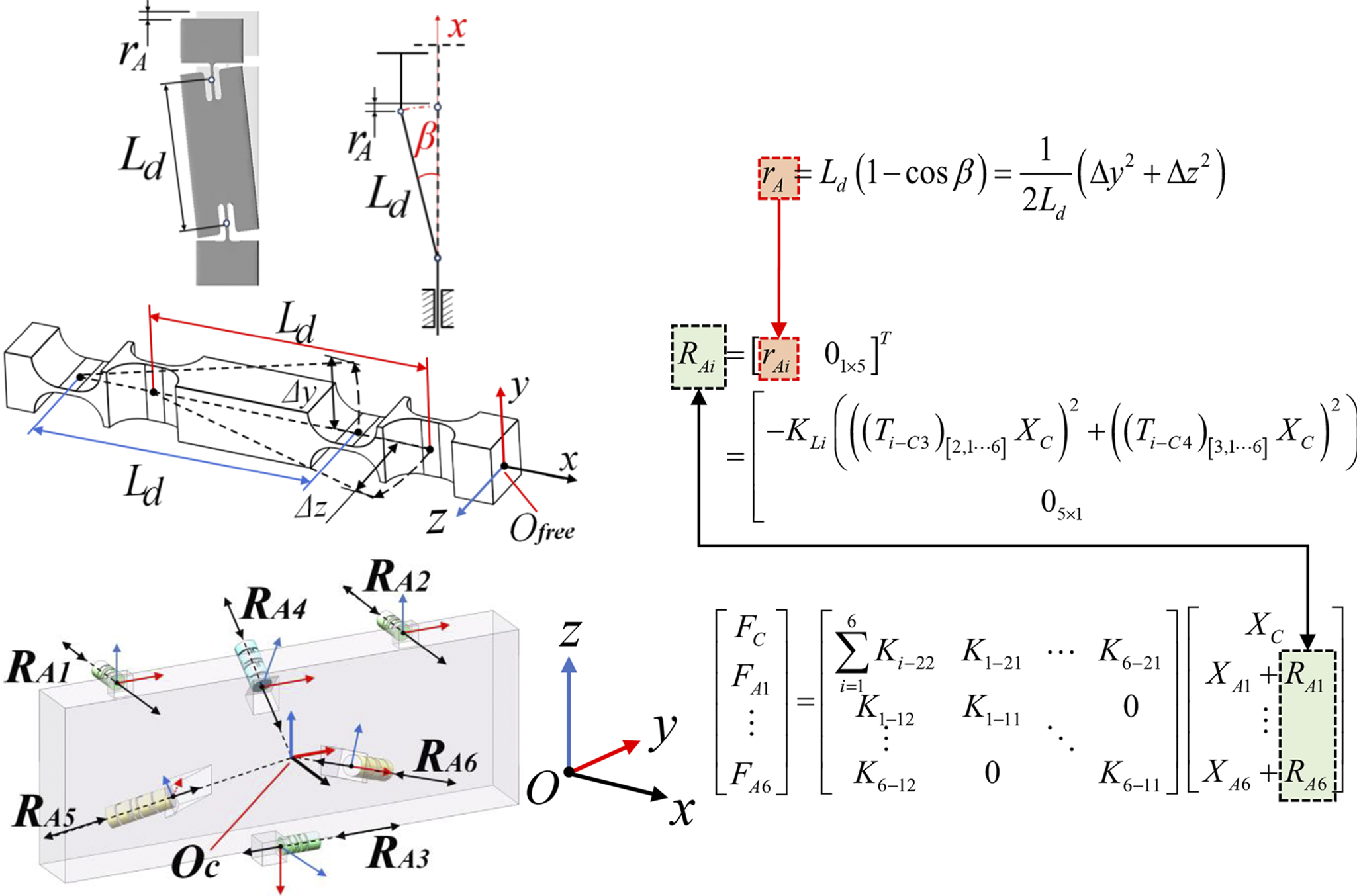
where L d denotes the distance between the corresponding flexure hinges, β represents the deflection angle of the flexure hinge, K Li represents the distance coefficient of the ith flexure chain and Δy and Δz are the displacements of the calculation point of the flexure chain along the y-axis and z-axis, respectively.
Based on the coordinate transformation in Equation (2), the axial variation at the end of each flexure chain caused by motion interdependence is defined accordingly:
 $$\begin{align} \begin{array}{@{}l}{\boldsymbol{R}}_{\mathrm{A}i}={\left[{\boldsymbol{r}}_{\mathrm{A}i}\kern0.5em {\mathbf{0}}_{1\times 5}\right]}^{\mathrm{T}}\\ \qquad\!\! ={\left[\begin{array}{@{}cc@{}}-{K}_{\mathrm{Li}}\left({\left({\left({\boldsymbol{T}}_{i-\mathrm{C}4}\right)}_{\left[2,:\right]}{\boldsymbol{X}}_{\mathrm{C}}\right)}^2+{\left({\left({\boldsymbol{T}}_{i-\mathrm{C}3}\right)}_{\left[3,:\right]}{\boldsymbol{X}}_{\mathrm{C}}\right)}^2\right)& \!\!{\mathbf{0}}_{1\times 5}\end{array}\right]}^{\mathrm{T}},\end{array}\end{align}$$
where T i−C3 and T i−C4 are the inverse transformation matrices from the center point O C to the end points O 3 and O 4 of the flexure hinges in the ith chain (see Figures 1(a) and 2(b)) and (T i−C4 ) [j,:] denotes the jth row of the transformation matrix T i−C4.
2.3 Modeling of input errors in actuation and transmission
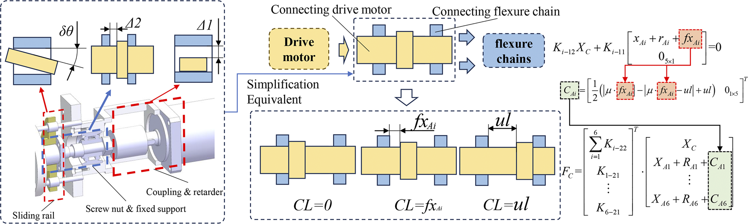
Due to the high load of the proposed adjustment mechanism, commonly used precision actuation methods cannot simultaneously meet the requirements for load capacity and stroke. Therefore, a rigid transmission structure driven by motors is adopted. However, assembly clearances, transmission backlash and elastic deformations in key components (such as ball screws and flexible couplings) can lead to actuation stagnation or hysteresis, significantly compromising the positioning accuracy of the mechanism. Based on the clearance mechanism illustrated in Figure 4 and the relationship in Equation (3), the axial force equilibrium of the chain is formulated as Equation (6). Subsequently, the actual additional equivalent structural gap displacement C Ai for the ith chain is derived, as shown in Equation (7):
 $$\begin{align}{\boldsymbol{K}}_{i-12}{\boldsymbol{X}}_{\mathrm{C}}+{\boldsymbol{K}}_{i-11}\left[\begin{array}{@{}c@{}}{\boldsymbol{x}}_{\mathrm{A}i}+{\boldsymbol{r}}_{\mathrm{A}i}\\ {}{\mathbf{0}}_{5\times 1}\end{array}\right]+{\boldsymbol{K}}_{i-11}\left[\begin{array}{c}f{\boldsymbol{x}}_{\mathrm{A}i}\\ {}{\mathbf{0}}_{5\times 1}\end{array}\right]=0,\end{align}$$
 $$\begin{align}{\boldsymbol{C}}_{\mathrm{A}i}={\left[\begin{array}{@{}cc@{}}\frac{1}{2}\left(\left|\mu \cdot f{\boldsymbol{x}}_{\mathrm{A}i}\right|-\left|\mu \cdot f{\boldsymbol{x}}_{\mathrm{A}i}- ul\right|+ ul\right)& {\mathbf{0}}_{1\times 5}\end{array}\right]}^{\mathrm{T}},\end{align}$$
Schematic diagram and theoretical relationship of transmission and joint clearance.
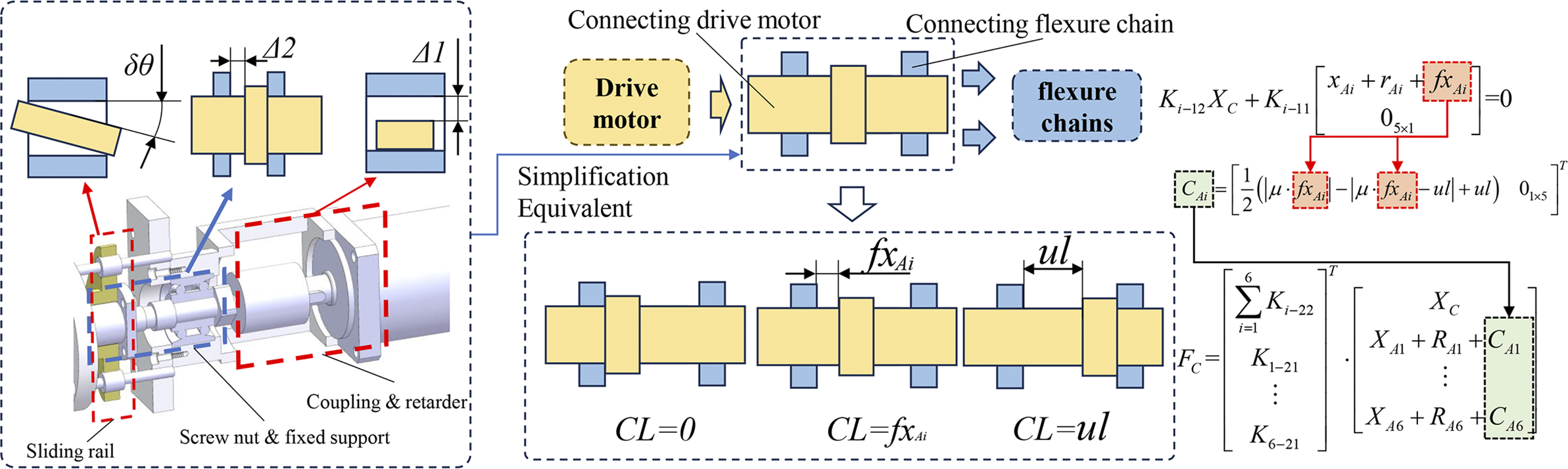
where f x Ai denotes the virtual displacement required to fully balance the axial force resulting from flexible deformation and gravity in the ith chain. For computational convenience, friction and clearance effects are integrated and defined as the hysteresis coefficient μ and the equivalent clearance CL, respectively. Here, ul represents the maximum displacement caused by structural clearances, r Ai denotes the axial deformation displacement of the corresponding flexure chain, x Ai denotes the theoretical axial input displacement for the corresponding flexure chain and K i−jk denotes the 6×6 block stiffness matrix located at the jth row and kth column of the ith flexure chain, as shown in the formulation of Figure 1(a).
Based on the axial load–gap relationship described by Equations (6) and (7), the computational state of the mechanism can be classified into two categories depending on the effect of structural clearance.
-
(1) Gap-free region: all chains operate in a fully engaged, clearance-free state. In this case, modeling emphasizes the nonlinear effects introduced by strain energy in the compliant structure and parasitic motion. Errors can be accurately modeled, and compensation performance remains reliable.
-
(2) Gap region: at least one chain is in a floating state due to structural clearance. In this case, both the force equilibrium condition and the sliding behavior of the gap must be considered for the affected chain. The model supports both forward and inverse solutions between the input X i and the output X C under such conditions.
By combining Equations (4)–(7), the overall equilibrium relationship of the mechanism is formulated as Equation (8), enabling the forward and inverse solutions between the input X i and the output X C for such compliant mechanisms:
 $$\begin{align} \begin{array}{l}\left[\begin{array}{c}{\boldsymbol{F}}_{\mathrm{C}}\\ {\boldsymbol{F}}_{\mathrm{A}1}\\ \vdots \\ {\boldsymbol{F}}_{\mathrm{A}6}\end{array}\right]=\left[\begin{array}{cccc}\sum \limits_{i=1}^6{\boldsymbol{K}}_{i-22}& {\boldsymbol{K}}_{1-21}& \dots & {\boldsymbol{K}}_{6-21}\\ {\boldsymbol{K}}_{1-12}& {\boldsymbol{K}}_{1-11}& \cdots & 0\\ \vdots & \vdots & & \vdots \\ {\boldsymbol{K}}_{6-12}& 0& \cdots & {\boldsymbol{K}}_{6-11}\end{array}\right]\\ \qquad\qquad\qquad\!\!\cdot \left[\begin{array}{c}{\boldsymbol{X}}_{\mathrm{C}}\\ {\boldsymbol{X}}_{\mathrm{A}1}+{\boldsymbol{R}}_{\mathrm{A}1}+{\boldsymbol{C}}_{\mathrm{A}1}\\ \vdots \\ {\boldsymbol{X}}_{\mathrm{A}6}+{\boldsymbol{R}}_{\mathrm{A}6}+{\boldsymbol{C}}_{\mathrm{A}6}\end{array}\right],\end{array}\end{align}$$
where R Ai represents the axial variation at the end of each flexure chain due to motion interdependence, and C Ai denotes the actual additional equivalent structural gap displacement of the ith chain.
3 Identification and calibration of error parameters
3.1 Sensitivity analysis of error sources
A coupling relationship exists between clearance-related errors and manufacturing or assembly errors. To reduce the calibration workload of the error model, it is necessary to screen error sources and eliminate those with low sensitivity.
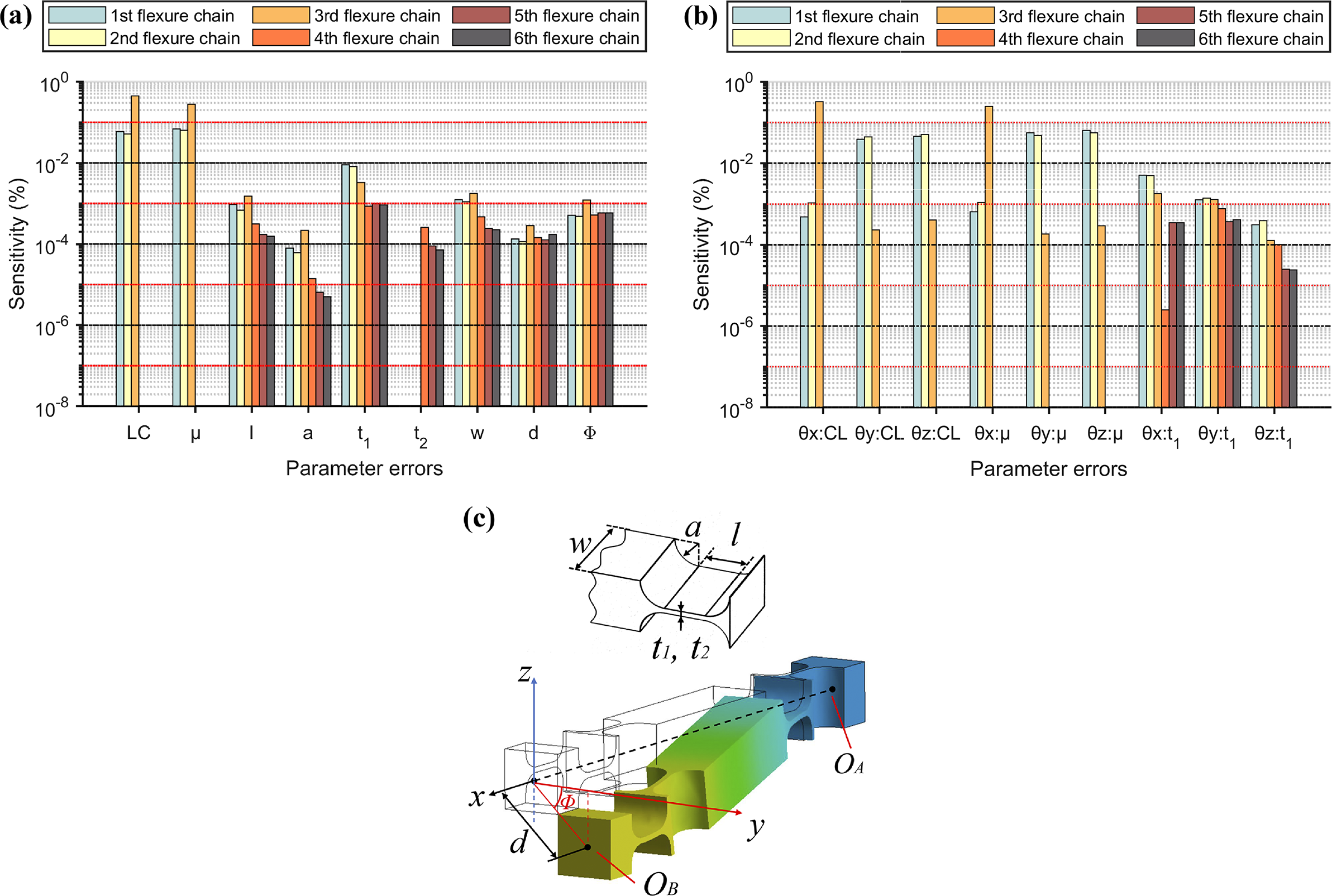
The distribution range for structural design parameter errors is set to ±10%. Assembly and creep errors are confined within a circular region with a 2 mm radius centered on the axis of the mounting hole. The equivalent hysteresis coefficient ranges from 0.75 to 1.00, and the equivalent clearance ranges from 0 to 0.5 mm. After screening, 45 error sources are defined for the mechanism, and each actual error value P is expressed as follows:
 $$\begin{align}P={P}_0+P'={P}_0+\left[\left(\Delta {P}_{\mathrm{max}}-\Delta {P}_{\mathrm{min}}\right)\cdot \eta +\Delta {P}_{\mathrm{min}}\right],\end{align}$$
where P
0 denotes the ideal value, $P' $
is the deviation value, ΔP represents the distribution range of each parameter error and η is the percentage coefficient generated based on the Sobol sequence, which also represents the mapped location along the boundary of the corresponding dimension within the hypercube activity domain used in the subsequent PSO algorithm.
$P' $
is the deviation value, ΔP represents the distribution range of each parameter error and η is the percentage coefficient generated based on the Sobol sequence, which also represents the mapped location along the boundary of the corresponding dimension within the hypercube activity domain used in the subsequent PSO algorithm.
The analysis is conducted using the Sobol global sensitivity analysis model, and the detailed procedure is as follows[ Reference Sobol 44 , Reference Saltelli, Ratto, Andres, Campolongo, Cariboni, Gatelli, Saisana and Tarantola 45 ].
-
(1) Initial sample generation: an N×2D sample matrix is generated using either the Monte Carlo method or a low-discrepancy sequence (e.g., Sobol sequence). The matrix is then divided into two independent sample sets, M A and M B, where N is the number of base samples and D is the number of error sources.
-
(2) Construction of mixed matrices: for each error source, the ith column of M A is replaced with the corresponding column of M B to construct a mixed matrix M AB (i) . A total of D such mixed matrices are generated:\
(10)where M A[i] and M B[i] represent the data in the ith column of the respective sample matrices M A and M B. $$\begin{align}{\boldsymbol{M}}_{\mathrm{A}\mathrm{B}}^{(i)}=\left[\begin{array}{@{}l@{\ \ \ }l@{\ \ \ }l@{\ \ \ }l@{\ \ \ }l@{\ \ \ }l@{\ \ \ }l@{}}{\boldsymbol{M}}_{\mathrm{A}\left[1\right]}& \dots & {\boldsymbol{M}}_{\mathrm{A}\left[i-1\right]}& {\boldsymbol{M}}_{\mathrm{B}\left[i\right]}& {\boldsymbol{M}}_{\mathrm{A}\left[i+1\right]}& \dots & {\boldsymbol{M}}_{\mathrm{A}\left[D\right]}\end{array}\right],\end{align}$$
-
(3) Model evaluation: the error model is evaluated using the samples from M A, M B and each M AB (i) . This results in a total of N×(D+2) model evaluations, from which the error values are calculated according to Equations (8) and (9):
(11)where P i represents the ith error source, f(.) denotes the total pose deviation between the error model (as defined in Equation (8)) and the ideal model under a specific set of error parameters P, θ i and θ i–target are the three attitude angle components of X C, representing the actual and target values, respectively, at the ith data point among the total n points in each misalignment curve, and n denotes the number of measured data points corresponding to n distinct posture configurations.
$$\begin{align}Y=f\left(\left[\begin{array}{@{}cccc@{}}{P}_1& {P}_2& \dots & {P}_D\end{array}\right]\right)=\sum \limits_{i=1}^n{\left\Vert {\boldsymbol{\theta}}_i-{\boldsymbol{\theta}}_{i-\mathrm{target}}\right\Vert}_2/n,\end{align}$$
-
(4) Variance decomposition and sensitivity index calculation: based on the principle of variance decomposition, the total variance of the model output deviation is computed, and the total-effect Sobol index is subsequently derived. The total sensitivity Sobol index is calculated as follows[ Reference Saltelli, Ratto, Andres, Campolongo, Cariboni, Gatelli, Saisana and Tarantola 45 ]:
(12)where j denotes the total sensitivity Sobol index corresponding to the jth error source, P ~j denotes the set of all input variables except the jth variable, Var(Y) represents the total variance of the model output Y and Var P~j [.] denotes the variance taken over all variables except Pj . The EPj [.] denotes the expectation taken with respect to Pj , while keeping all other variables fixed.
$$\begin{align}{S}_{\mathrm{T}j}=1-\frac{{\mathrm{Var}}_{P_{\sim j}}\left({E}_{P_j}\left[Y\left|{P}_{\sim j}\right.\right]\right)}{\mathrm{Var}(Y)},\kern0.84em j=1,2,\dots, 45, \end{align}$$


To mitigate the influence of sample-based variability on the accuracy of the total-effect Sobol indices, numerical experiments and statistical methods are employed for validation, focusing on the following aspects.
-
(1) Convergence analysis: the base sample size N is adjusted to observe the fluctuation trend of the total-effect Sobol indices for various error sources. In the present model, the indices tend to stabilize when N ≈ 400. Therefore, a base sample size of N = 500 is selected, yielding a total of 23,500 samples, with each sample set corresponding to one misalignment curve.
-
(2) Numerical properties: according to the Sobol index formulation, certain mathematical properties hold, such as S Ti ≥ Si and the non-negativity of S Ti .
-
(3) Cross-validation: the consistency of total-effect Sobol indices is examined by calculating them from independently generated sample sets using different generation schemes.
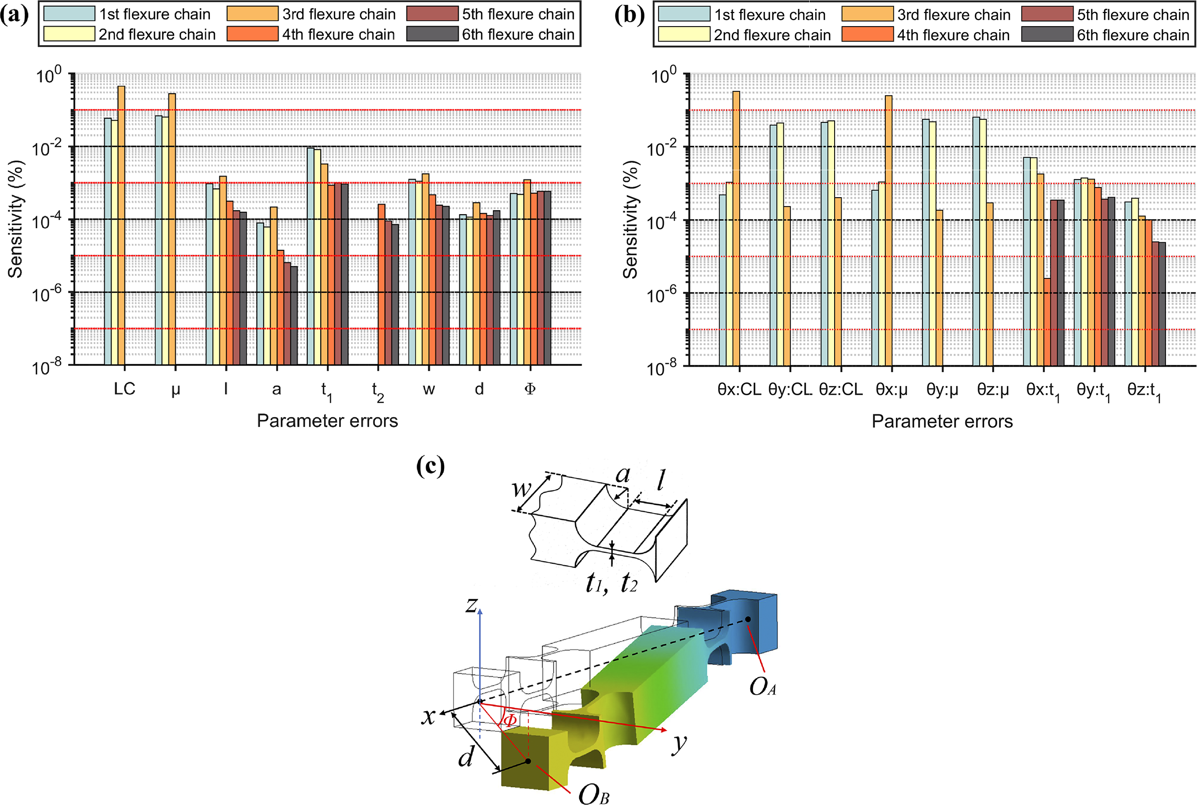
The normalized sensitivity distribution is shown in Figure 5. The results indicate that the clearance size and the equivalent hysteresis coefficient are the most significant contributors to system errors, whereas machining and assembly errors have relatively smaller impacts, although their influence on fitting accuracy remains non-negligible. In addition, θx (rotation) is mainly affected by parameters of the third chain, whereas θy (tip) and θz (tilt) are primarily influenced by parameters of the first and second chains.
The global sensitivity index (GSI) of parameter errors: (a), (b) sensitivity distribution of the 45 error sources; (c) definition of partial error source parameters. Here, w denotes the hinge width, a is the fillet radius, l is the segment length, t 1 and t 2 are thicknesses used in the flexure hinges of the tripod remote-center mechanism and d and Φ denote the magnitude and direction of the flexure chain offset, respectively.
3.2 Improved PSO-based parameter identification and calibration
The target trajectory for calibration is discretized into multiple independent data points, with the relative driving inputs between points known in advance. By combining Equations (8)–(11), the corresponding misalignment values are calculated. The identification problem is thus transformed into minimizing the deviation rate via the fitness function f(gbest), with the goal of obtaining the global optimal solution gbest. Since the pose uniquely corresponds to the input, a theoretical minimum of f(gbest) = 0 exists. Accordingly, the objective function for parameter error identification based on the measured platform pose is thus established as follows:
 $$\begin{align}f\left(\mathrm{gbest}(j)\right)=\sum \limits_{i=1}^M{\left\Vert {\boldsymbol{\theta}}_i-{\boldsymbol{\theta}}_{i-\mathrm{target}}\right\Vert}_2/M,\end{align}$$
where j denotes the jth particle, and each particle contains measurement data from M posture points. The attitude angle θ i is calculated by substituting the actual input X Ai and the error parameters P into Equation (8).
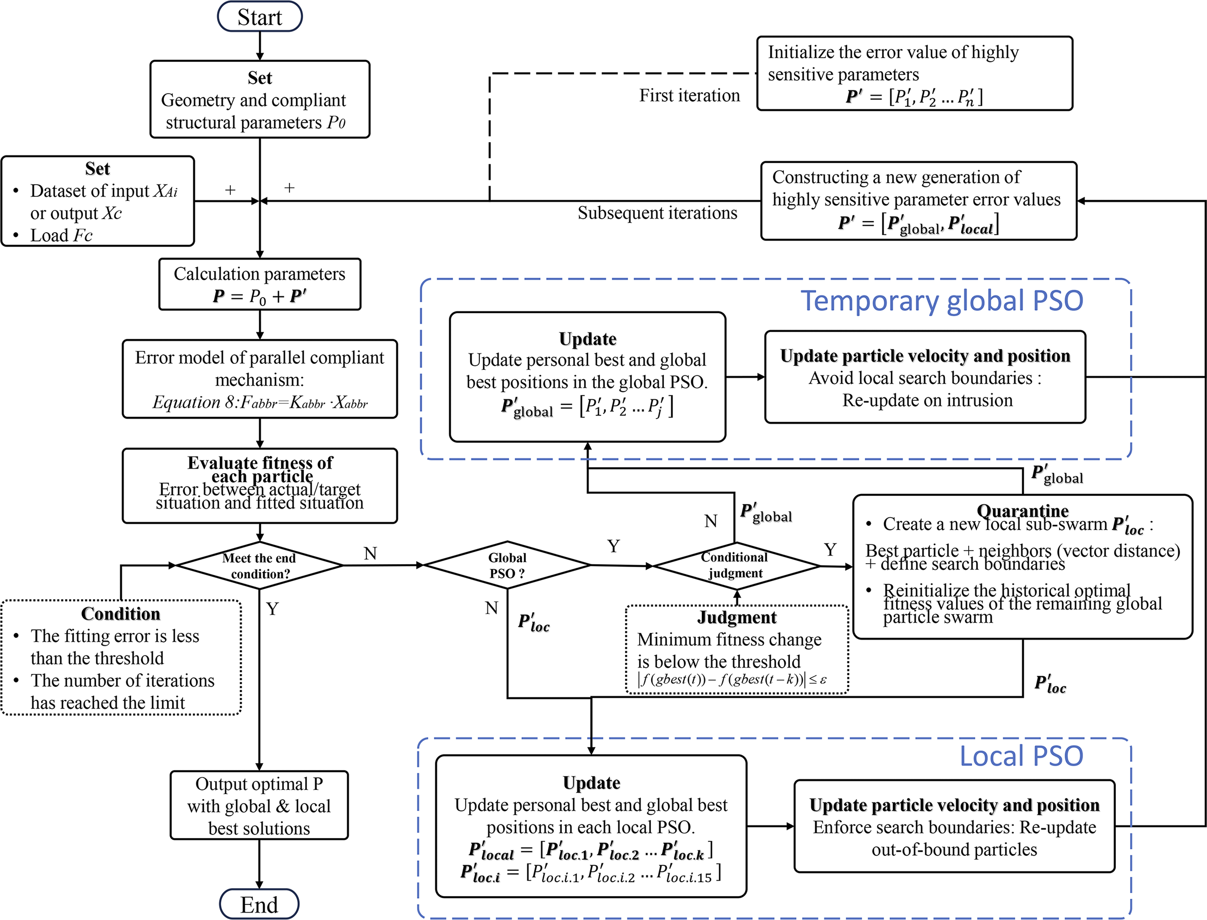
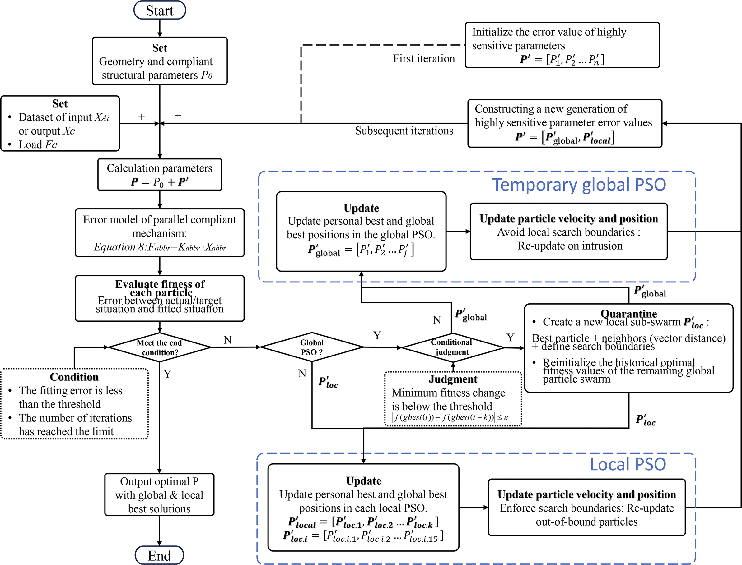
Based on the proposed PSO algorithm, a dynamic multi-subpopulation cooperative strategy is introduced. Its core mechanism is that, during the global particle swarm iteration, when the global best fitness f(gbest) satisfies the stagnation condition defined in Equation (14) for k consecutive iterations, a refined local search subpopulation is constructed by selecting neighboring particles based on a spatial proximity criterion (e.g., Euclidean distance) centered on the current global best solution. This subpopulation performs its search within a defined hypercube domain, with particle movements strictly confined through position correction and velocity damping mechanisms to prevent search overflow. An independent local best updating strategy is applied within the subpopulation, enabling deep exploration of the optimal region without interference from the global swarm:
 $$\begin{align}\Delta {f}_{\mathrm{global}}=\left|f\left(\mathrm{gbest}(t)\right)-f\left(\mathrm{gbest}\left(t-k\right)\right)\right|\le \varepsilon,\end{align}$$
where t is the current iteration number, ε is the predefined threshold and k is the tolerance window length used to determine whether the global search has stagnated in a local optimum trap.
To restore global exploration diversity, all parameters of the remaining global particle swarm are reset to eliminate the limiting effect of historical information on population diversity. When a global particle enters the search domain of any local subpopulation, its position is projected and corrected, or its velocity direction is reversed, to ensure spatial decoupling between global exploration and local exploitation.
The overall algorithm flow is illustrated in Figure 6. The main hyperparameters are defined as follows: the particle count is set to 300 and the total number of iterations is 150. The initial distribution is generated using a quasi-Monte Carlo algorithm. The inertia weight ω starts at 0.8 and linearly decreases to 0.4 during the iteration process. The acceleration coefficients c 1 and c 2 are both set to 2.0. The maximum velocity in each dimension is set to 3%–7% of the corresponding parameter range. According to the global sensitivity analysis, dimensions with higher sensitivity are assigned lower maximum velocity limits. For subpopulation partitioning, the isolation region is defined as a hypersphere with a radius of 0.1 in the normalized vector space, centered on the selected particle. A maximum of 20 particles can be isolated in each round, and the upper limit for each local subpopulation is 6 particles.
Error calibration flowchart based on an improved particle swarm algorithm.
3.3 Simulation verification
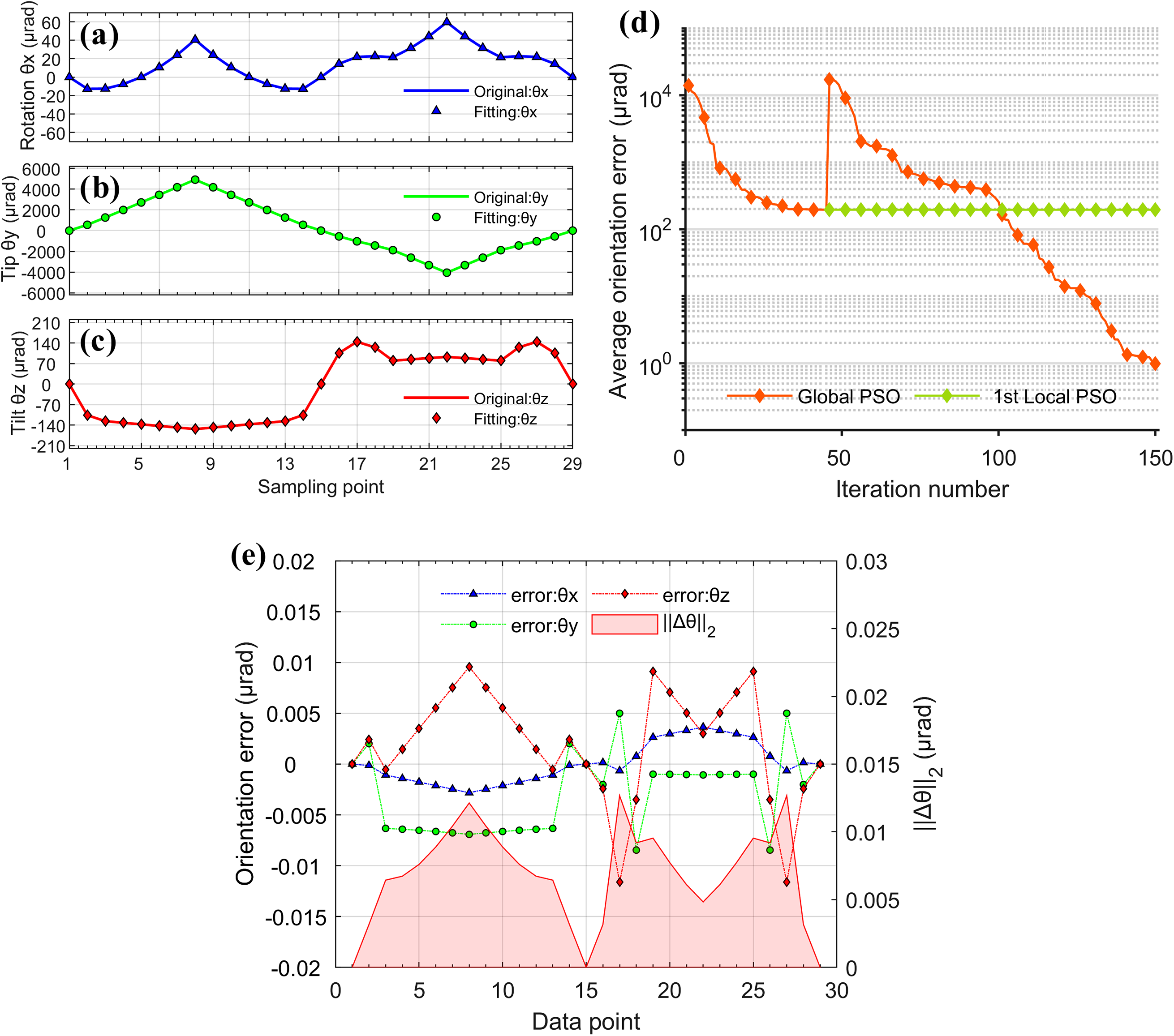
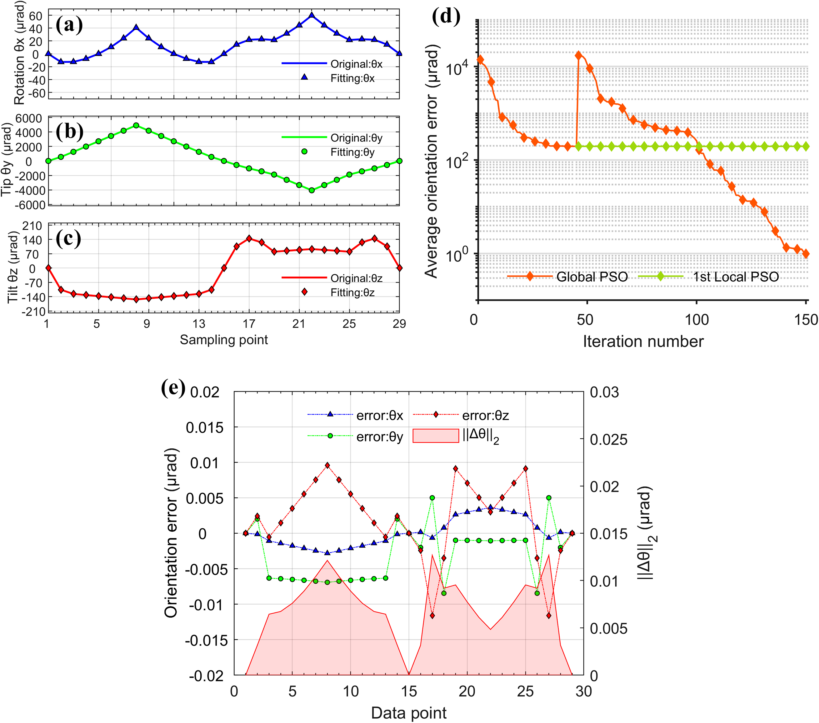
Preset error values are introduced into the ideal finite element model to generate simulated misalignment curves. The curves are then fitted and identified using the error model, and the results are compared against the initial preset values. The fitting results are shown in Figure 7, and the predefined and identified values of various error sources are listed in Table 1. ‘Initial position’ refers to the relative position of the flexure chain within the system under open-loop control. It is treated as an error source under the assumption that the initial position of the flexure chain is unknown during open-loop operation. The results show that the maximum identification deviations for the initial position of the driving module and the equivalent structural clearance are 2.7 $\unicode{x3bc} $
m and 0.02 mm, respectively; the maximum deviation in directional error is below 0.015
$\unicode{x3bc} $
m and 0.02 mm, respectively; the maximum deviation in directional error is below 0.015 $\unicode{x3bc} $
rad; the fitting error of the hysteresis coefficient is less than 1.3%; and the fitting errors of other low-sensitivity error sources are all below 10%. These results validate the effectiveness of the proposed calibration method both theoretically and numerically.
$\unicode{x3bc} $
rad; the fitting error of the hysteresis coefficient is less than 1.3%; and the fitting errors of other low-sensitivity error sources are all below 10%. These results validate the effectiveness of the proposed calibration method both theoretically and numerically.
Simulation results: (a)–(c) multi-directional misalignment with fitting curves; (d) iteration convergence; (e) residual error distribution.
Predefined and identified main parameters by simulation (unit for errors is mm).

4 Experimental validation
4.1 Experimental setup
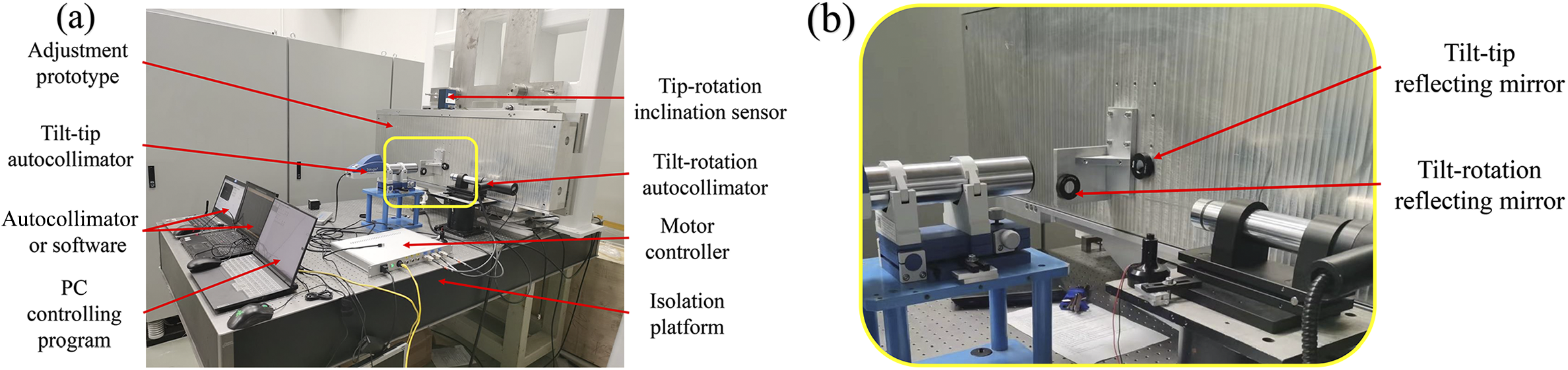
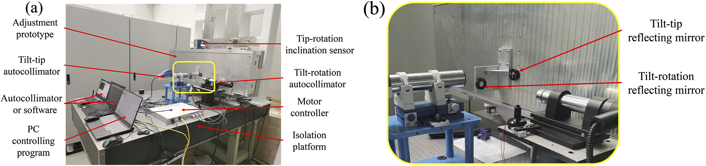
Taking a 1400 mm × 420 mm large-aperture diffraction grating adjustment mechanism as an example, the experimental setup comprises a measurement system and an adjustment frame, as illustrated in Figure 8. The measurement system employs two laser collimators to independently measure tip–tilt and tilt–rotation attitudes, and an additional inclinometer to measure tip–rotation attitudes, thereby ensuring measurement accuracy and enabling multi-channel cross-verification. Each attitude data point is extracted as the mean value from the stable interval during the settling phase following each adjustment operation.
Prototype testing: (a) experimental platform configuration; (b) collimator and mirror configuration layout.
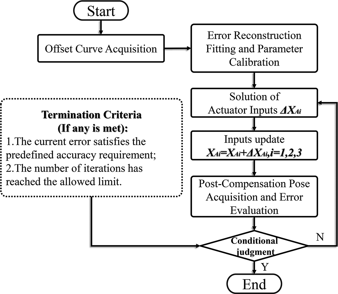
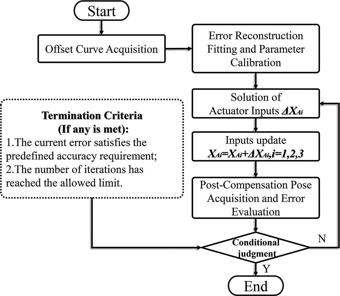
Under constant external loading, the adjustment characteristics of the mechanism remain stable. Therefore, the calibrated model can be used for multiple iterative approximations. In practical testing, a closed-loop iterative compensation strategy based on the error model is adopted, as illustrated in Figure 9. The procedure is as follows.
-
(1) Misalignment data acquisition: measure the initial posture error corresponding to the target configuration by averaging values over the stabilized interval.
-
(2) Error modeling and parameter identification: input the misalignment curve into the proposed error model, identify high-sensitivity error sources and complete parameter calibration.
-
(3) Inverse computation of input displacement: based on the calibrated model, compute the required actuation inputs (e.g., X A1, X A2, X A3) for the current posture.
-
(4) Posture correction and error measurement: re-drive the mechanism and record the resulting stabilized posture; then compute the deviation
${\Delta}$
X
C from the target configuration. -
(5) Iterative refinement until convergence: if
${\Delta}$
X
C remains large, repeat steps (3) and (4); terminate the process once the deviation meets the accuracy requirement or the maximum number of iterations is reached.


Error calibration procedure and posture approximation process.
4.2 Acquisition of misalignment data and calibration of error parameters
In open-loop control mode, actuators 1–3 are sequentially driven to perform reciprocal posture adjustments within the ranges of ±1 mrad@θx
, ±5 mrad@θy
and ±3 mrad@θz
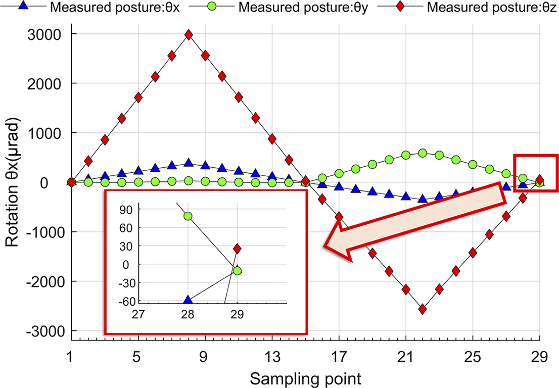
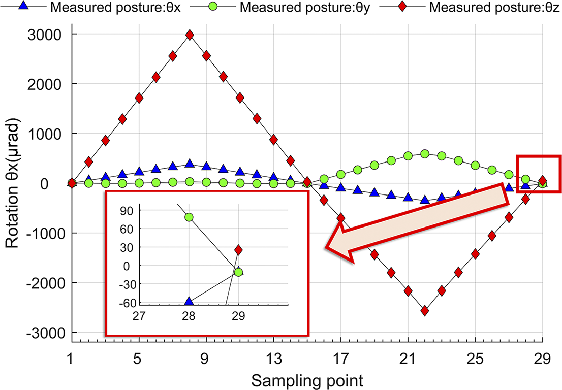
. The uncoupled posture response curves of the prototype are recorded, and 77 sets of raw posture data under misaligned conditions are selected for further analysis. During reciprocal motion, a noticeable offset is observed when the prototype returns to its original position. This offset is regarded as a form of systematic drift error that cannot be captured by the current error model. As illustrated in Figure 10, the drift errors in the three posture directions are approximately –10 $\unicode{x3bc} $
rad@θx
, −11
$\unicode{x3bc} $
rad@θx
, −11 $\unicode{x3bc} $
rad@θy
and +25
$\unicode{x3bc} $
rad@θy
and +25 $\unicode{x3bc} $
rad@θz
, respectively. These systematic errors reduce the identification accuracy of fitness evaluations in the PSO process. Therefore, before error modeling and parameter calibration, the raw misalignment curves must be corrected to eliminate the global offset. After completing this process, curve reconstruction and parameter fitting are performed.
$\unicode{x3bc} $
rad@θz
, respectively. These systematic errors reduce the identification accuracy of fitness evaluations in the PSO process. Therefore, before error modeling and parameter calibration, the raw misalignment curves must be corrected to eliminate the global offset. After completing this process, curve reconstruction and parameter fitting are performed.
Systematic offset error at the sampled points.
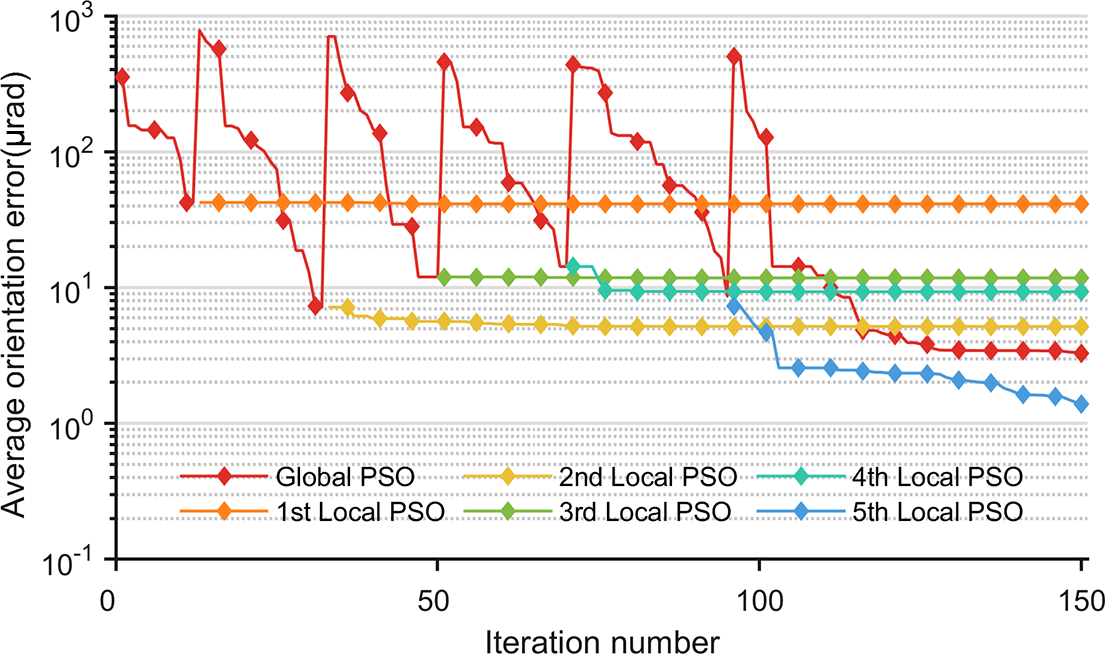
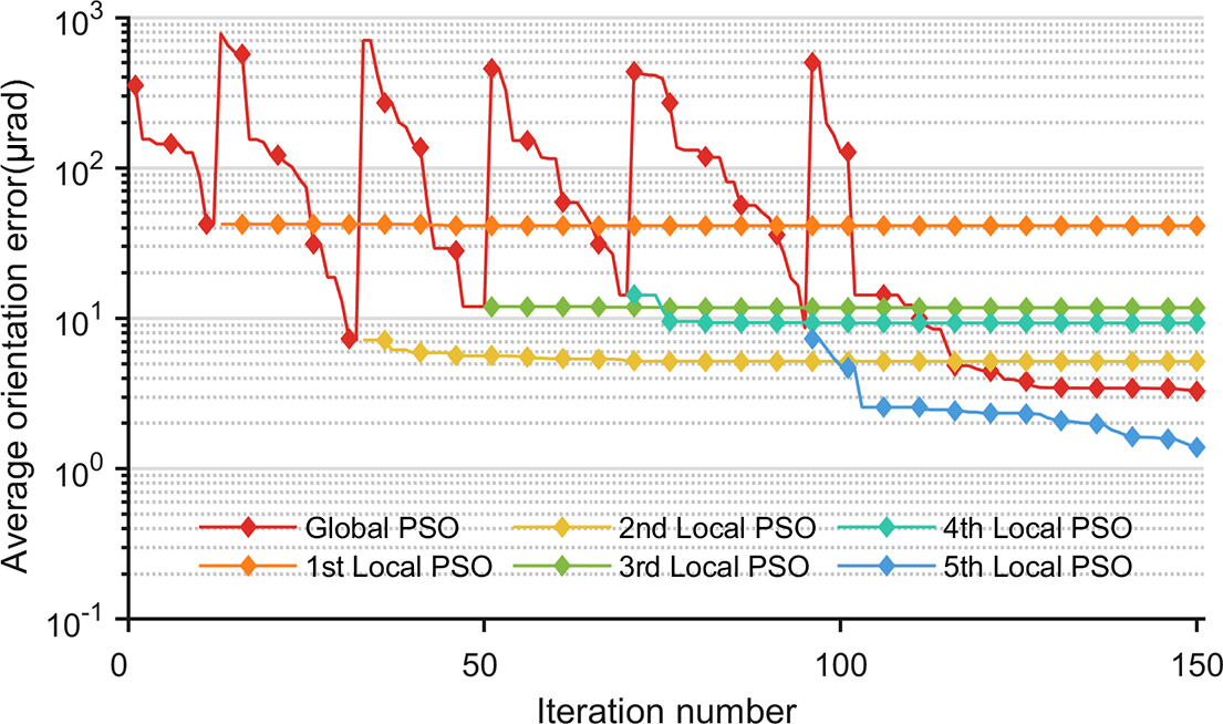
As shown in Figure 11, a temporary global particle swarm is introduced during the fitting process, yielding six sets of relatively optimal solutions. Among them, the solution with the minimum fitness function value (see Equation (12)) is selected as the final calibration result. Based on this result, the clearance state of each sampled posture point is classified using the error model as follows.
-
(1) Fitting S1: all compliant chains are in compression (non-clearance condition).
-
(2) Fitting S2: at least one compliant chain is in the clearance state.
-
(3) Fitting S3: the three compliant chains exhibit a combination of tensile and compressive states (non-clearance state).
Variation of the best residual error in each particle swarm during the iterative calibration of the measured offset posture.
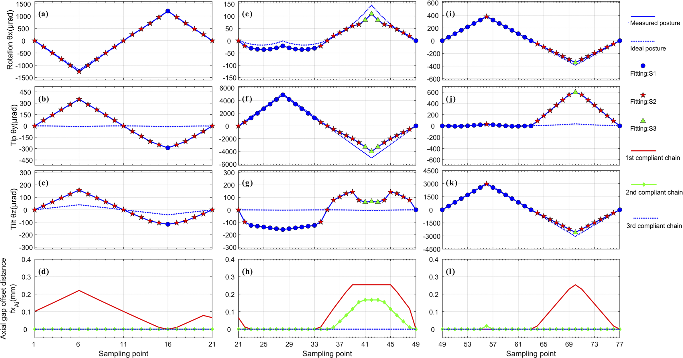
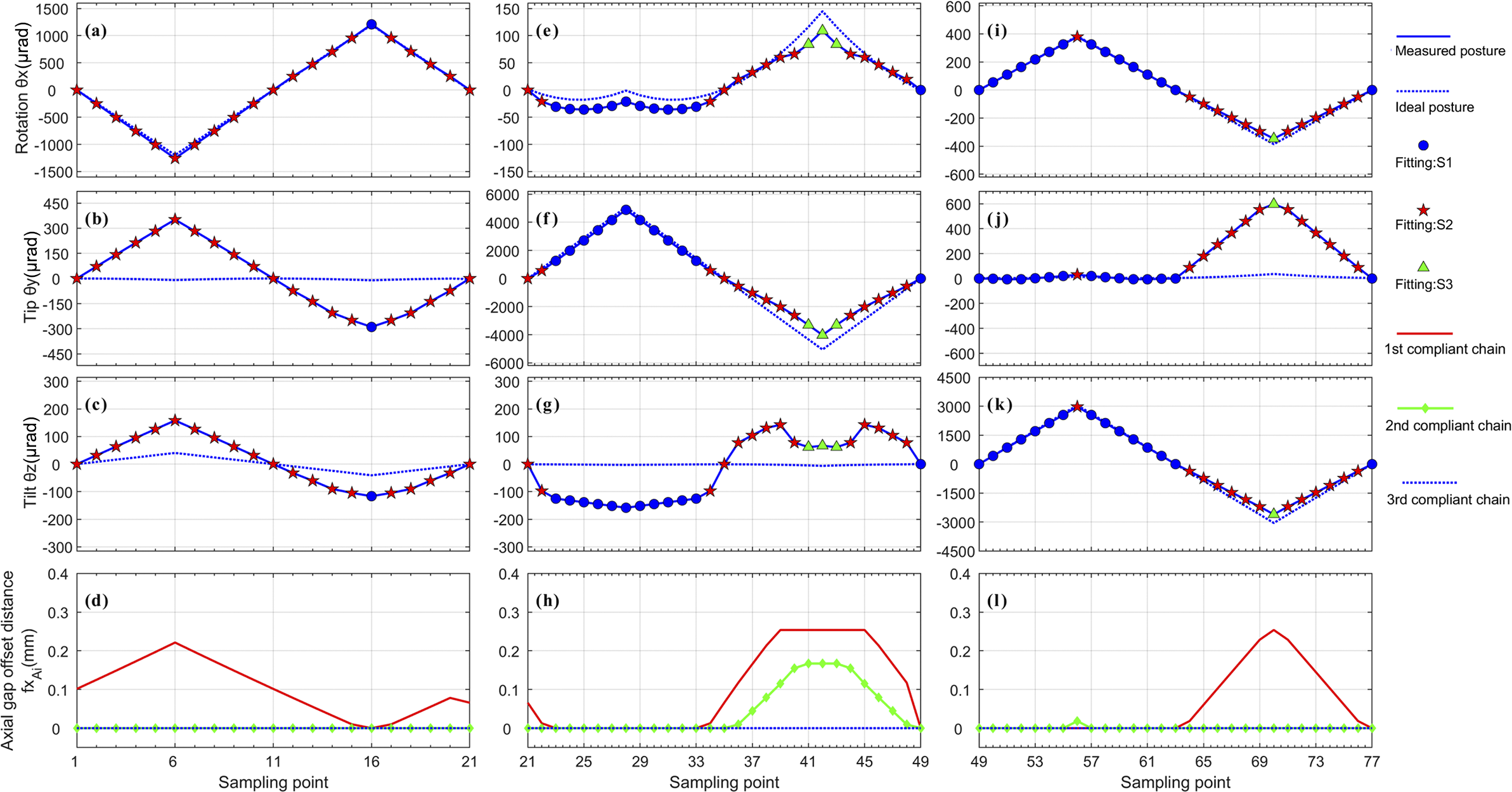
The corresponding fitting results are shown in Figure 12, and the error distributions under each clearance condition are summarized in Table 2.
Fitted offset postures in each direction after calibration, along with the corresponding mechanism states at sampled points. Fitting S1: all compliant chains are in compression (non-clearance state). Fitting S2: at least one compliant chain is in the clearance state. Fitting S3: the three compliant chains exhibit a combination of tensile and compressive states (non-clearance state).
Fitting results of offset postures after calibration and the corresponding mechanism states (remove systematic deviation).

Figures 12(d), 12(h) and 12(l) illustrate the error model’s predictions of the structural clearance state at each sampling point. The numerical values indicate the distance of each flexure chain from its equivalent clearance zero position (see fx Ai in Figure 4). For example, in Figure 12(d), the first flexure chain remains within the clearance region and shifts forward axially. According to the indexing defined in Figure 1, this state results in an increased tip angle and a decreased tilt angle.
Further examining Figures 12(a)–12(c), during sampling points 1–11, the value of fx A1 increases significantly, corresponding to an increase in posture error that aligns with the trend of the misalignment curve.
Similarly, in the region of sampling points 65–77 shown in Figures 12(i)–12(k), the same mechanism is observed: the first flexure chain moves backward while still remaining in the clearance region, resulting in forward parasitic displacement. This causes actuation loss and results in an actual posture that is lower than the ideal value.
In Figures 12(e)–12(h), during sampling points 33–42, the first and second flexure chains sequentially enter the clearance transition zone as they move backward. This results in a gradual reduction in tip adjustment capability. Around sampling point 34, the first chain exits the clearance region, causing a brief rebound in the tip angle. Once both chains exit the clearance region, actuation capacity is restored and posture variation returns to normal.
4.3 Validation of trajectory performance after offline compensation
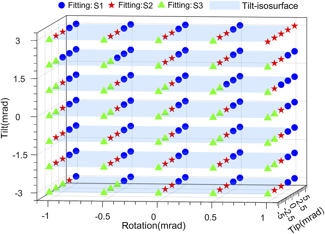
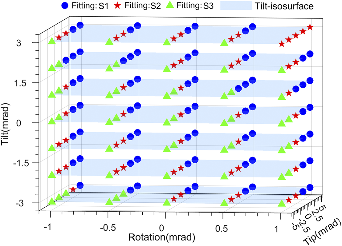
To further verify the effectiveness of the proposed method in correcting the posture of the meter-scale large-aperture compliant parallel adjustment mechanism, inverse calculations are carried out based on the calibrated error model. Starting from the defined zero posture, the required relative actuation inputs for the target positions shown in Figure 13 are computed.
Experimental results: spatial distribution of sampling and validation points. Let Si denote the chain force state classification. Fitting S1: all compliant chains are in compression (non-clearance state). Fitting S2: at least one compliant chain is in the clearance state. Fitting S3: the three compliant chains each exhibit a combination of tensile and compressive states (non-clearance state).
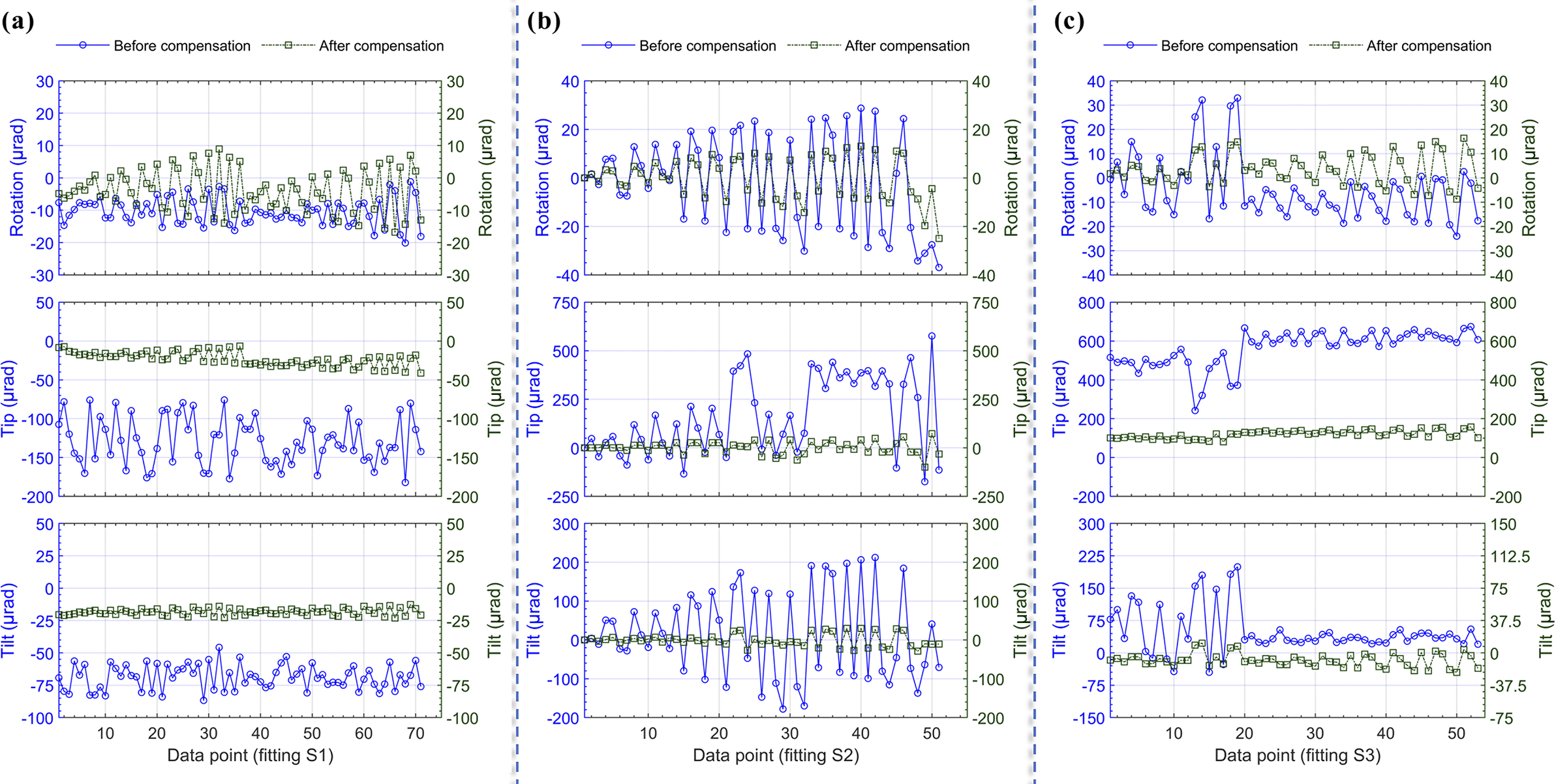
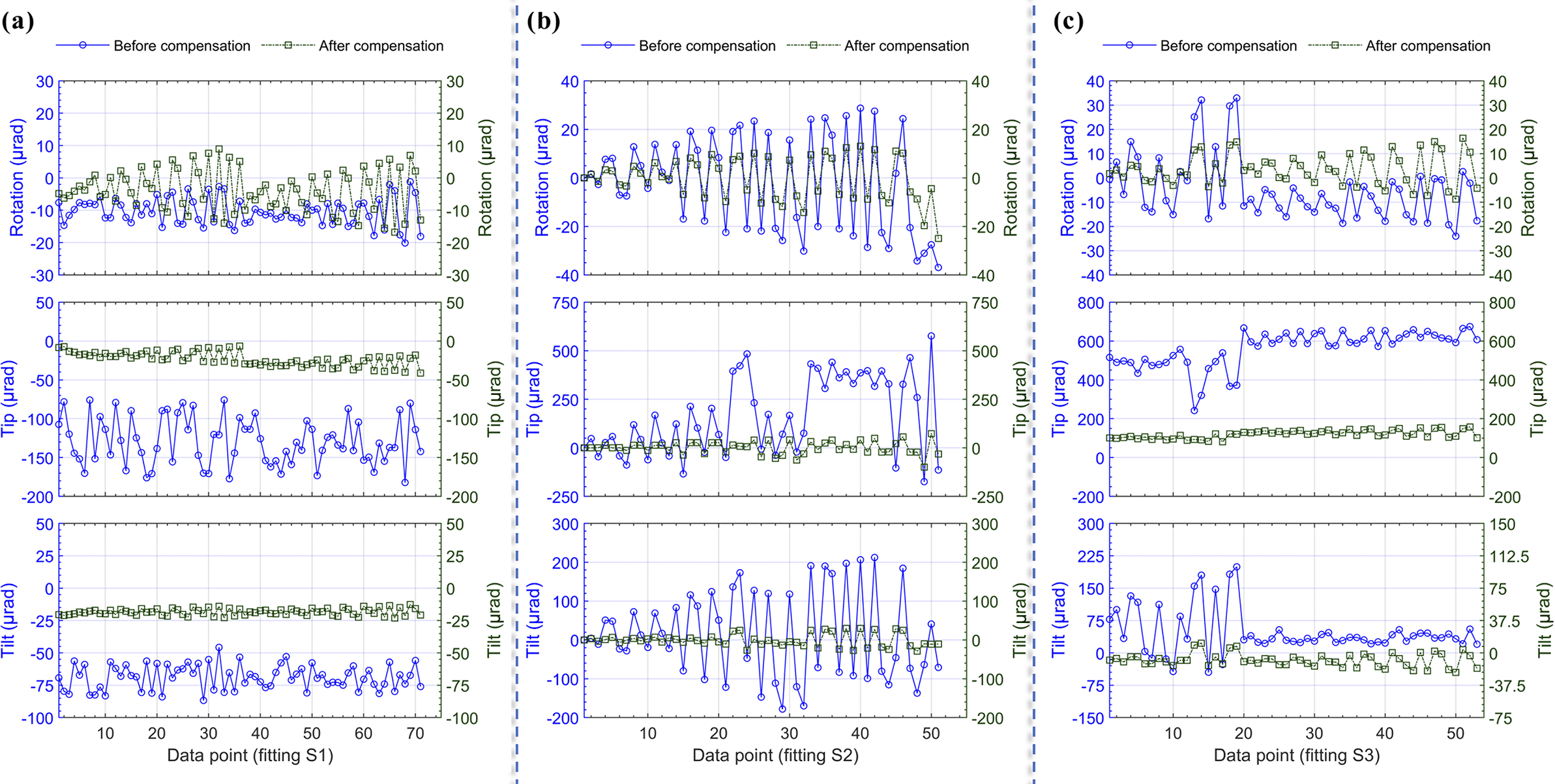
The initial compensation results based on the calibrated error model, along with the corresponding error reductions, are shown in Figure 14. The remaining errors are primarily attributed to modeling approximations in the flexure representation, systematic drift during data acquisition and unmodeled factors such as control and measurement errors.
Error situation: before and after compensation. (Data points are sorted in ascending order of total adjustment magnitude.)
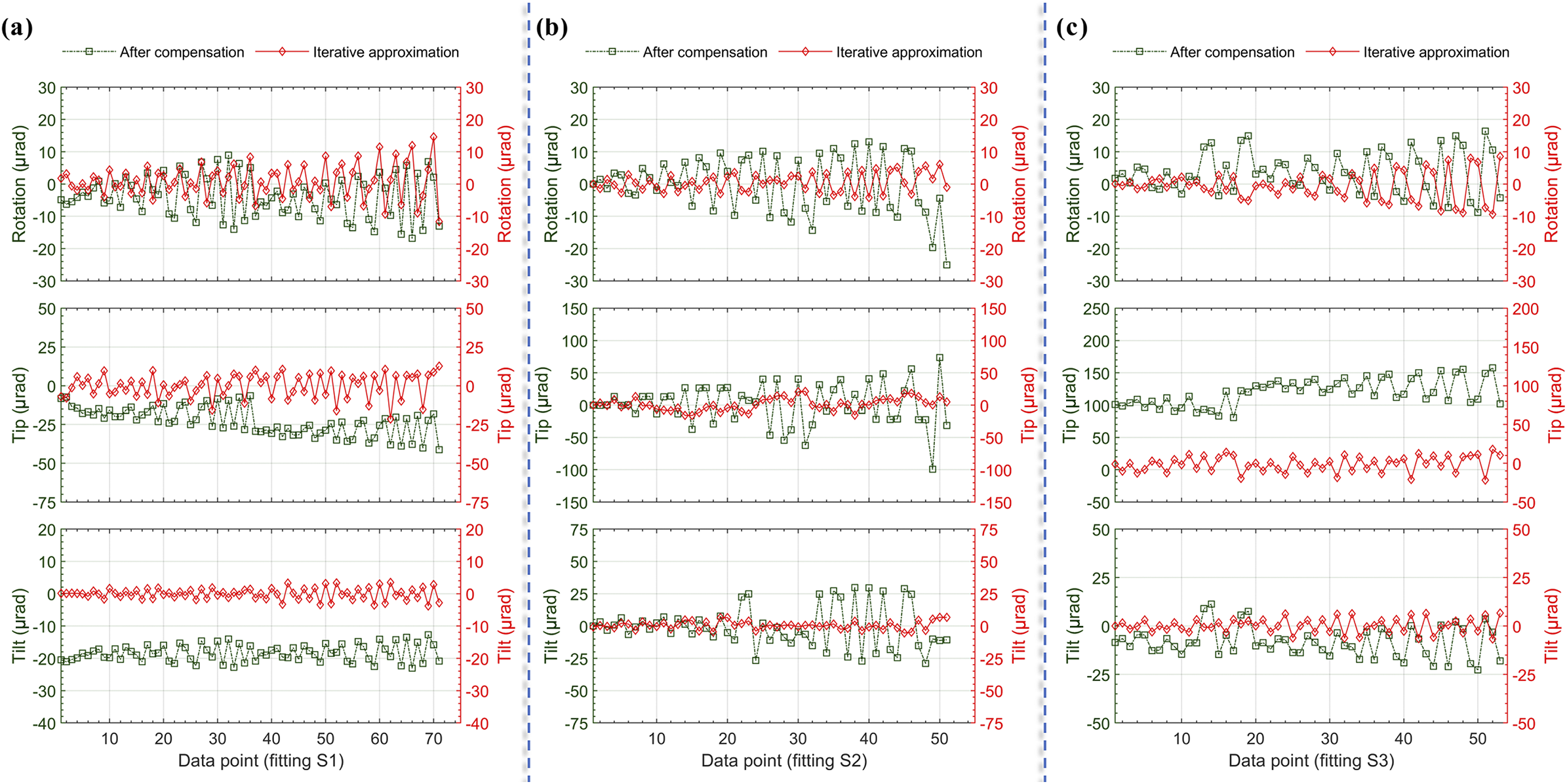
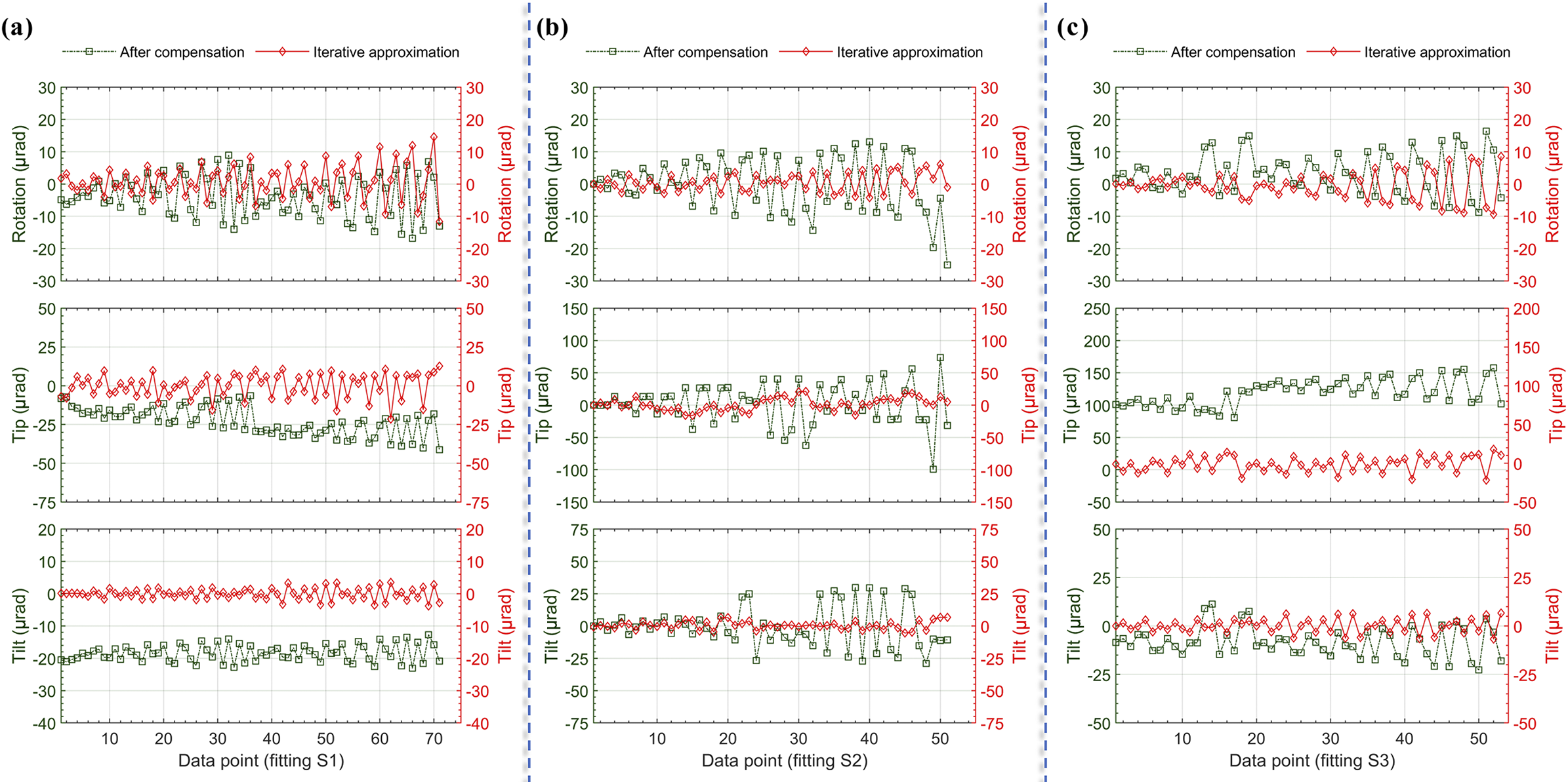
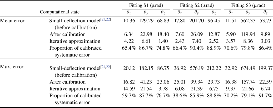
Building upon this, a closed-loop control strategy is adopted (as illustrated in Figure 9), in which the deviation between the current and target postures is used to compute corrective inputs via the error model. This enables progressive posture correction. The final relative accuracy is presented in Figure 15, with detailed numerical results provided in Table 3.
Error distribution after compensation and iterative approximation. (Data points are sorted in ascending order of total adjustment magnitude.)
Comparison of attitude deviations before and after calibration (units: $\unicode{x3bc} $
rad, absolute values).
$\unicode{x3bc} $
rad, absolute values).
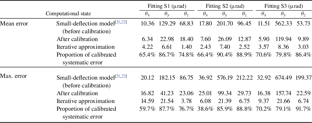
The results indicate that the maximum posture errors were reduced from 36.9, 674.5 and 212.2 $\unicode{x3bc} $
rad to 14.5, 21.5 and 6.7
$\unicode{x3bc} $
rad to 14.5, 21.5 and 6.7 $\unicode{x3bc} $
rad in the rotation, tip and tilt directions, respectively. As shown in Figure 14, the first-round compensation using the calibrated model achieved average error reductions of over 65.4%, 79.8% and 74.8%, respectively. Among these, the clearance region (fitting S2) contributed up to 38.6% of the maximum error. After full closed-loop iteration, the final average error reduction ratios exceeded 59.7%, 79.1% and 76.7% in the respective directions.
$\unicode{x3bc} $
rad in the rotation, tip and tilt directions, respectively. As shown in Figure 14, the first-round compensation using the calibrated model achieved average error reductions of over 65.4%, 79.8% and 74.8%, respectively. Among these, the clearance region (fitting S2) contributed up to 38.6% of the maximum error. After full closed-loop iteration, the final average error reduction ratios exceeded 59.7%, 79.1% and 76.7% in the respective directions.
In summary, the experimental results confirm that the proposed error model and calibration method significantly improve posture control accuracy for meter-scale heavy-load rigid–flexure hybrid parallel adjustment mechanisms.
5 Conclusion
This study tackles the challenge of nonlinear error modeling and compensation in high-precision posture adjustment of meter-scale, large-aperture optical elements supported by flexure-based parallel mechanisms. A kinetostatics-based modeling and error calibration method is proposed for heavy-load rigid–flexure hybrid structures, and an improved PSO algorithm is integrated to establish a comprehensive modeling–identification–compensation framework.
In the modeling phase, unlike conventional flexure modeling approaches typically applied to small-scale, lightweight and idealized structures, the proposed method combines compliance matrix techniques with energy-based modeling to characterize deformation energy. A pseudo-rigid-body modeling approach is introduced to capture parasitic displacements in meter-scale structures. In addition, an equivalent structural clearance model is developed to systematically describe the nonlinear effects arising from elastic deformation and backlash in components such as ball screws and flexure couplings. These behaviors are equivalently modeled through mechanical relationships and integrated into the parasitic displacement formulation.
The resulting model supports nonlinear coupling among input displacement, output displacement and external loads, and adaptively switches computational strategies based on the mechanism’s state (e.g., full contact or clearance-induced slip). This enables unified modeling of rigid, compliant and clearance behaviors, thereby enhancing the model’s applicability. For error identification, a global sensitivity analysis is conducted to pinpoint dominant error sources. A global–dynamic multi-swarm cooperative PSO algorithm is developed to enhance convergence stability and inverse identification accuracy in high-dimensional nonlinear systems.
Based on this model, a closed-loop error compensation strategy is implemented and experimentally verified on a prototype platform. Through feedback-driven iterative correction, the maximum posture errors are reduced from 36.9, 674.5 and 212.2 $\unicode{x3bc} $
rad to 14.5, 21.5 and 6.7
$\unicode{x3bc} $
rad to 14.5, 21.5 and 6.7 $\unicode{x3bc} $
rad, respectively. These results verify the effectiveness of the proposed method in addressing error modeling and compensation for meter-scale, heavy-load, rigid–flexure hybrid mechanisms. The study provides a viable technical approach for precision alignment, posture control and error compensation in large-scale structural applications such as high-power laser systems.
$\unicode{x3bc} $
rad, respectively. These results verify the effectiveness of the proposed method in addressing error modeling and compensation for meter-scale, heavy-load, rigid–flexure hybrid mechanisms. The study provides a viable technical approach for precision alignment, posture control and error compensation in large-scale structural applications such as high-power laser systems.
Acknowledgements
This work was supported by the Project of Chinese Academy of Sciences (Grant No. 23XR0256) and the Strategic Priority Research Program of the Chinese Academy of Sciences (Grant Nos. XDA25020203, XDA25020101 and XDA25020103).






 Open access

