


Introduction
In modern wireless communication, waveguide-slotted arrays are good candidates for on-board and airborne antenna systems, especially dual-polarized antennas have been widely used [Reference Wang, Jin, Liang and Zhang1–Reference Li, Kang, Wei, Cai and Yin3].
In [Reference Li, Kang, Wei, Cai and Yin3–Reference Kahar and Mandal6], a dual-polarized microstrip array antenna is designed; however, the microstrip antenna has more losses. In [Reference He, Ding, Zhang, Zhang and Du7], a new material is used to reduce the losses, but it still reaches 0.17 dB. In [Reference Zhao, Ban, Sun and Li8–Reference Ding and Cheng11], substrate-integrated waveguide dual-linear polarization antenna is designed. A 45° linearly polarized slot array antenna with differential dual-end feeding network is proposed in [Reference Zhou and Hong9]. A novel dual-band dual-polarized aperture-shared slotted waveguide antenna array with high efficiency is presented in [Reference Ding and Cheng11]. In [Reference Chen, Fang, Wang, Zhang and Huang12–Reference Ferrando-Rocher, Herranz-Herruzo, Valero-Nogueira and Baquero-Escudero15], dual polarization is achieved by orthogonal slots on two waveguides, respectively. In [Reference Zhang, Wang, Chen, Zou and Liang16], a dual-band antenna was designed using a gap waveguide as the transmission structure. In [Reference Wang, Jin, Lu and Zhong17], dual polarization is achieved at the horizontal and vertical slots of the ridge waveguide and E-plane waveguide, respectively. In summary, all of them have complex transmission structure.
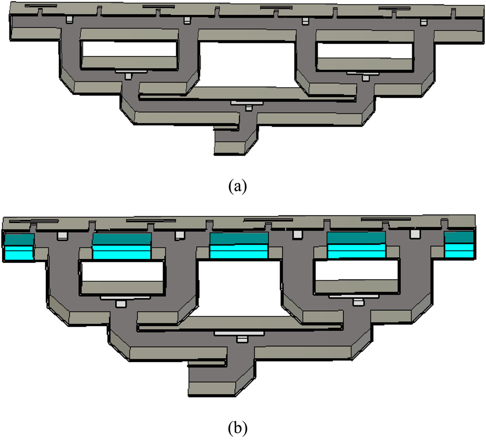
A dual-band dual-linearly polarized waveguide slot array antenna is proposed in this paper. Horizontal and vertical electric fields radiate from orthogonal slots on the broad side. Two grooves change the phase velocity and have less losses. A 1 × 8 array has been designed, which the pattern has no gate lobe and the side lobe level has not deteriorated. The measured results show horizontal and vertical polarization are realized in 9.39–9.78 and 11.62–12.3 GHz, respectively. The overall model is shown in Fig. 1, which includes radiation slots, groove, and power divider.
Model of the antenna: (a) overview of the antenna and (b) sectional view of the antenna.

Antenna design
Lower and upper band design
Horizontal polarization is realized by a horizontal slot, which is shown in Fig. 2(a). The length of horizontal radiation slot is l 1. The vertical polarization is radiated from longitudinal slot with length l 2, as shown in Fig. 2(b). d 1 and d 2 are the distance between the slot's center and the short-circuit wall. The end of the waveguide is a short-circuit wall, and there is only one radiation slot on the broad side.
(a) Model of horizontal polarization antenna; (b) the model of vertical polarization antenna; and (c) the simulated S 11 (l 1 = 12 mm, l 2 = 15 mm).

When electromagnetic waves transmit in WR-75, according to the waveguide wavelength formula:

λg > λ, where λg is the waveguide wavelength and λ is the free-space wavelength, a is broad dimension of waveguide. The distance between the center of the slot and the short-circuit wall is λg/2, which is about one-half of the waveguide wavelength.
When simplifying array distribution as uniform linear array, the normalized shunt admittance of each slot is identically assumed as y, which is shown in Fig. 3. According to the transmission line theory, we can define a function f(y) as follows:

Equivalent transmission line model of N-element slotted uniform linear array terminated in a short circuit.

Finding the complex roots of the f(y) = 0 can solve out y. The reflection coefficient S 11 can be extracted from electromagnetic simulation software [Reference Wang, Zhong, Zhang and Liang18].
Fig. 2(c) depicts the simulated input impedance bandwidth (IBW) of the units. The IBW of the horizontal polarization unit for S 11 < −10 dB is from 10–10.75 GHz. It is 10.6–12.1 GHz for S 11 < −10 dB of the vertical polarization unit.
Dual-band unit design
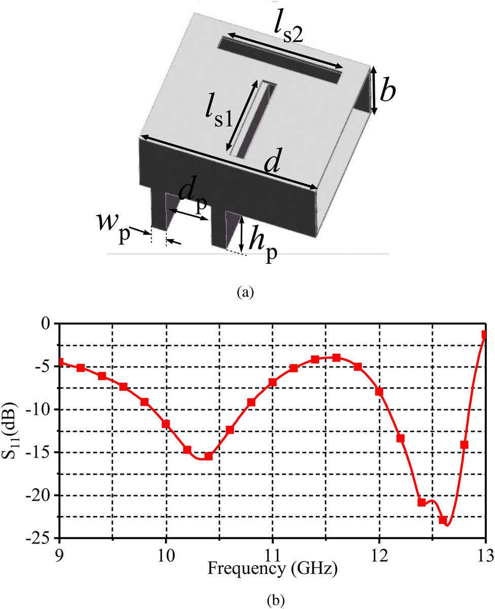
The antenna must be able to generate vertically polarized electric fields and horizontally polarized electric fields to realize dual polarization. Figure 4(a) shows the structure. The broad side is slit orthogonal slots. The length of the two slots is ls 1 and ls 2, respectively. Because the center position of the two slots is the same in the y direction, their distances from the short-circuit wall are dy.
Simulated dual-band unit of S 11.

However, due to mutual coupling between the horizontal and vertical slots, which impacts the radiation, the resonant frequency has been shifted. The IBW is shown in Fig. 4(b). The S 11 < −10 dB in 9.85–10.4 and 11.5–12.6 GHz. Figure 5 shows simulated current density at 10.25 and 12 GHz. A vertically polarized electric field is formed when the antenna operates at 10.25 GHz, and a horizontally polarized electric field is generated at 12 GHz. When the distance between two units is more than one free-space wavelength, the side lobe level will worse than −13 dB. The distance, along the y axis, between the center of the radiation slot and the radiation short-circuit wall is dy. When the array is designed, the distance will have a significant impact on the side lobe.
Simulated surface current distribution of the unit.

Phase-compensated groove design
By adjusting the phase velocity, the side lobes can be suppressed and the antenna's compactness can be improved. Generally, adding the medium into the waveguide changes the phase velocity. However, there are two grooves with the same shape at the bottom of the waveguide in this paper. The dielectric-added and non-grooved antennas are shown in Fig. 6. The experiment is shown in Fig. 7, which is a radiation pattern comparison diagram of filling medium, with groove and without groove at 9.6 GHz. The operating frequency band is the same, but the side lobes of the antenna are different. The loss of the metal structure is less than filling medium. It can be found from Fig. 7 that the pattern side lobes for filling the medium and adding grooves are below −14.8 dB. The side lobe of the antenna pattern without adding the grooves is −11.9 dB. Adding grooves not only has less losses, but it can also effectively change the phase velocity. Because the waveguide is partially filled with medium, the equivalent dielectric constant is different from that of the medium itself. In addition, the equivalent dielectric constant generated by the groove is dispersive, and different frequencies need to use different dielectric constants for alternative simulation. The configured dielectric constant of the filled medium set in the simulation varies with the frequency between 8.45 and 5.3.
(a) Without groove antenna array and (b) dielectric-added and non-grooved antenna array.
Patterns of three antenna array.

When the antenna is arrayed, the distance between the units is d. The radiation slot and the short-circuit wall is d/2, two similar grooves are added, which effectively suppress the side lobes. The structure is shown in Fig. 8, the antenna becomes more compact.
(a) Model with two grooves at the bottom and (b) the S 11 of the model.
Groove parameters analysis
A dual-polarized antenna was designed in the previous section. When the reflected electric field reachs radiation slots and comes in contact with the transmission electric field, the two electric fields with the same phase are superimposed on each other, which improves the radiation efficiency.
The narrow dimension b of the waveguide does not affect the λg of TE10 mode. However, when the variation of b is combined with the groove design, the radiation of the horizontal slot will be major affected. When b = 8.5, b = 9.5 and b=10.5, the resonance frequency has been changed in the lower band, while the depth of resonance has been affected in the upper band. b = 9.525 mm is finally chosen to operate in better and more acceptable isolation (Fig. 9).
Parametric analysis of the b of S 11.

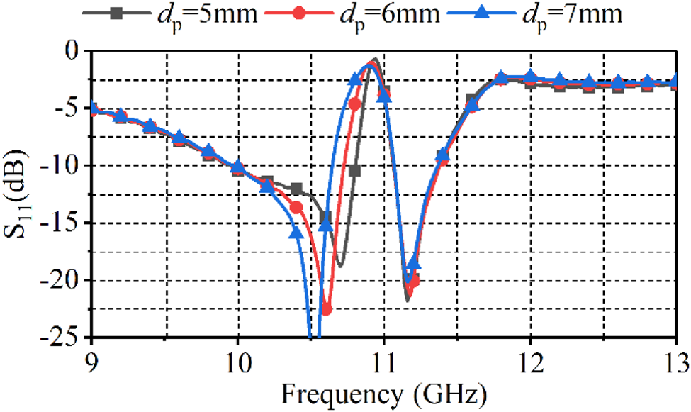
As the groove affects the phase velocity, the values of wp, hp, and dp are simulated in Figs 10–12, respectively. When hp = 8 mm or hp = 9 mm, the operating frequency is shifted and the performance becomes worse in the lower band. When hp = 8.5 mm, the S 11 < −10 dB can be achieved in 9.95–10.55 and 10.95–11.45 GHz. When wp = 1 mm or wp = 2 mm, the operating frequency will shift, which has effect on the upper band seriously. When wp = 1.5 mm, the S 11 < −10 dB can be achieved in 9.95–10.55 and 10.95–11.45 GHz. When dp = 5 mm, the curve shifts to high frequency in the lower band; when dp = 7 mm, the curve shifts to low frequency in the lower band, so d p affects the lower band.
Parametric analysis of the dp of S 11.
Parametric analysis of the wp of S 11.

Parametric analysis of the hp of S 11.

The length of the radiation slot l s1 and l s2 determines by the operating frequency and λg. The length l s1 and l s2 are adjusted for the case of with or without groove respectively. The simulation results are shown in Figs 4 and 8. When the values of ls 1 and ls 2 are inappropriate, the short-circuit wall cannot form the short-circuit requirements, so the energy of the antenna cannot be radiated normally.
Antenna array design and measurement
A 1 × 8 array antenna has been designed. Four 1 × 2 antenna arrays are connected by power divider. In order to simplify the design, when connecting 1 × 2 array elements, the short-circuit wall structure is removed in the connected position, and the electric field forms a virtual short-circuit wall in the same position. The overall structure is shown in Fig. 1, in which the dotted line part is a virtual short-circuit wall, and three virtual short-circuit walls are formed. Due to the coupling effect and edge effect of the array, the structural parameters in the array have been comprehensively optimized, and the final parameters are shown in Table I.
Optimized parameters of the array antenna

The prototype of the antenna is shown in Fig. 13, and the antenna dimension is 149 mm × 24.1 mm × 58.6 mm. The antenna can be functionally divided into two parts: power-divider feed and radiation structure. However, during manufacturing, in order to reduce the cutting of the current in the waveguide cavity, the antenna is divided into two symmetrical parts along the y-axis and connected by multiple screws.
Fabricated antenna.
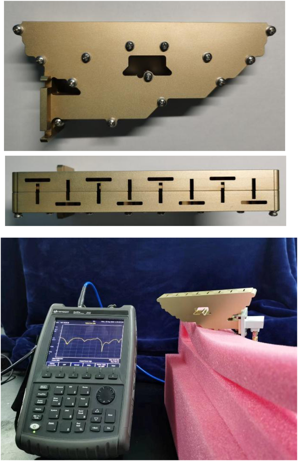
According to the measured results, the S 11 are shown in Fig. 14. From the results, S 11 < −10 dB in 9.39–9.78 and 11.62–12.3 GHz, respectively. As the units of the array interact with each other, the operating frequency changes compared with the single unit. If considering the potential impact of measurement environment and fabrication tolerance , especially the influence of chamfer during machining, the measured results are basically consistent with the simulation results. The antenna can achieve S 11 < −10 dB in lower and upper bands, respectively.
Simulated and measured S 11.

The pattern is one of the important indicators, which is shown in Fig. 15. The antenna patterns of vertical polarized (VP) and horizontal polarized (HP) on the xoz and yoz planes were measured at 9.6 and 12 GHz, respectively. As can be seen from Fig. 15, the side lobe level can reach −14 dB and no grating lobe is generated in the pattern, which proves the groove can effectively compensate the phase difference between the units. The cross-polarization level is about −14 dB. The antenna structure is simple, and the beam is not scanned. Similar antennas mentioned in the paper are compared in Table 2.
Measured and simulated normalized radiation patterns of VP array and HP array: (a) yoz-plane at 9.6 GHz, (b) xoz-plane at 9.6 GHz, (c) xoz-plane at 12 GHz, and (d) yoz-plane at 12 GHz.

Comparison with some previous works

Conclusion
In this paper, we designed a dual-linear dual-band waveguide slot antenna with low side lobe. Two grooves are added at the bottom of the antenna. Orthogonal slots slit on the broad side realizes dual polarization. Dual band is realized in 9.39–9.78 GHz and 11.62–12.3 GHz. The former is horizontal polarization, and the latter is vertical polarization. The side lobe level of the antenna can reach −14 dB.
Financial support
This research received no specific grant from any funding agency, commercial, or not-for-profit sectors.
Conflict of interest
The authors report no conflict of interest.
 Jun Gao obtained his MS degree in electronic science and technology from the University of Information Engineering in 2018. His main research interests include aperture antennas and beam-steering antennas.
 Tianpeng Li received his BS and MS degrees from Air Force Engineering University, Xi'an, China, in 2012 and 2016, respectively. He is currently working at the Information Engineering University. His main research interests include antennas and propagation.
 Hai Wang received his BS degree from Logistical Engineering University, Chongqing, China, in 2015. He is currently pursuing his MS degree at Information Engineering University. His main research interests include aperture antennas, wideband antennas, and wide axial ratio antennas.
 Xue Lei received her BS and MS degrees from Information Engineering University in 1989 and 2000, respectively. She is currently working at Information Engineering University. Her main research interests include antennas and electromagnetic wave propagation.
 Kexin Wang obtained his MS degree in electronic science and technology from the University of Information Engineering in 2022, and he is currently pursuing his Ph.D. in information and communication engineering. His current research interests include phased arrays, side lobe suppression, and optimization algorithms.


 Open access