





1. Introduction
An essential property of turbulence is that it is dissipative. Turbulence dissipation plays a key role in all turbulent flows. The scaling of the turbulence dissipation rate is pivotal in theories and models of turbulent flow statistics and dynamics (e.g. Tennekes & Lumley Reference Tennekes and Lumley1972).
The Kolmogorov scale-by-scale equilibrium for homogeneous stationary turbulence leads to a well-known expression for the turbulence dissipation rate $\epsilon$
(Batchelor Reference Batchelor1953; Tennekes & Lumley Reference Tennekes and Lumley1972; Sreenivasan Reference Sreenivasan1984; Frisch Reference Frisch1995):
$\epsilon$
(Batchelor Reference Batchelor1953; Tennekes & Lumley Reference Tennekes and Lumley1972; Sreenivasan Reference Sreenivasan1984; Frisch Reference Frisch1995): $\epsilon = C_{\epsilon }k^{3/2}/L$
, where
$\epsilon = C_{\epsilon }k^{3/2}/L$
, where $k$
is the turbulent kinetic energy,
$k$
is the turbulent kinetic energy, $L$
is a measure of the largest turbulent eddies in the flow (an integral length scale) and
$L$
is a measure of the largest turbulent eddies in the flow (an integral length scale) and $C_{\epsilon }$
is a dimensionless coefficient independent of Reynolds number. The Kolmogorov equilibrium means that the average rate
$C_{\epsilon }$
is a dimensionless coefficient independent of Reynolds number. The Kolmogorov equilibrium means that the average rate $C_{\epsilon }k^{3/2}/L$
with which the large turbulent eddies lose energy to smaller eddies equals the average rate with which the turbulence loses energy by viscous dissipation. However, a different turbulence dissipation scaling has emerged over the past 15 years in various turbulent flows where non-stationarity (including streamwise decay/non-homogeneity) cannot be overlooked: freely decaying periodic turbulence (Goto & Vassilicos Reference Goto and Vassilicos2016b
) where a significantly long early time range exists where
$C_{\epsilon }k^{3/2}/L$
with which the large turbulent eddies lose energy to smaller eddies equals the average rate with which the turbulence loses energy by viscous dissipation. However, a different turbulence dissipation scaling has emerged over the past 15 years in various turbulent flows where non-stationarity (including streamwise decay/non-homogeneity) cannot be overlooked: freely decaying periodic turbulence (Goto & Vassilicos Reference Goto and Vassilicos2016b
) where a significantly long early time range exists where $C_{\epsilon }$
grows while the Taylor length-based Reynolds number decreases; and decaying turbulence generated by fractal or regular grids (Vassilicos Reference Vassilicos2015), turbulent bluff body wakes (Castro Reference Castro2016) and turbulent jets (Cafiero & Vassilicos Reference Cafiero and Vassilicos2019) where a long centreline near-region exists where
$C_{\epsilon }$
grows while the Taylor length-based Reynolds number decreases; and decaying turbulence generated by fractal or regular grids (Vassilicos Reference Vassilicos2015), turbulent bluff body wakes (Castro Reference Castro2016) and turbulent jets (Cafiero & Vassilicos Reference Cafiero and Vassilicos2019) where a long centreline near-region exists where $C_{\epsilon }$
increases whilst
$C_{\epsilon }$
increases whilst $ \textit{Re}_{\lambda }$
decreases along the streamwise direction. In all these cases,
$ \textit{Re}_{\lambda }$
decreases along the streamwise direction. In all these cases, $C_{\epsilon }$
and
$C_{\epsilon }$
and $ \textit{Re}_{\lambda }$
vary according to
$ \textit{Re}_{\lambda }$
vary according to $C_{\varepsilon } \sim \sqrt {Re_{G}}/Re_{\lambda }$
, where
$C_{\varepsilon } \sim \sqrt {Re_{G}}/Re_{\lambda }$
, where $ \textit{Re}_G$
is some global Reynolds number characterising inlet/initial/boundary conditions. Time fluctuations of
$ \textit{Re}_G$
is some global Reynolds number characterising inlet/initial/boundary conditions. Time fluctuations of $C_{\epsilon }$
and
$C_{\epsilon }$
and $ \textit{Re}_{\lambda }$
in forced periodic turbulence (Goto & Vassilicos Reference Goto and Vassilicos2015; Goto & Vassilicos Reference Goto and Vassilicos2016a
) and in atmospheric turbulence (Waclawczyk et al. Reference Waclawczyk, Nowak and Malinowski2022a
, Reference Waclawczyk, Nowak, Siebert and Malinowski2022b
) follow the exact same scaling:
$ \textit{Re}_{\lambda }$
in forced periodic turbulence (Goto & Vassilicos Reference Goto and Vassilicos2015; Goto & Vassilicos Reference Goto and Vassilicos2016a
) and in atmospheric turbulence (Waclawczyk et al. Reference Waclawczyk, Nowak and Malinowski2022a
, Reference Waclawczyk, Nowak, Siebert and Malinowski2022b
) follow the exact same scaling: $C_{\epsilon }$
increases as
$C_{\epsilon }$
increases as $ \textit{Re}_{\lambda }$
decreases and
$ \textit{Re}_{\lambda }$
decreases and $C_{\epsilon }$
decreases as
$C_{\epsilon }$
decreases as $ \textit{Re}_{\lambda }$
increases following
$ \textit{Re}_{\lambda }$
increases following $C_{\varepsilon } \sim \sqrt {Re_{G}}/Re_{\lambda }$
.
$C_{\varepsilon } \sim \sqrt {Re_{G}}/Re_{\lambda }$
.
Whilst the non-equilibrium dissipation scaling $C_{\varepsilon } \sim \sqrt {Re_{G}}/Re_{\lambda }$
seems to define a rather wide universality class of time fluctuations and streamwise profiles, it is not fully universal. A similar anticorrelation in time fluctuations of the Taylor length-based Reynolds number and various definitions of
$C_{\varepsilon } \sim \sqrt {Re_{G}}/Re_{\lambda }$
seems to define a rather wide universality class of time fluctuations and streamwise profiles, it is not fully universal. A similar anticorrelation in time fluctuations of the Taylor length-based Reynolds number and various definitions of $C_{\epsilon }$
was found in fully developed turbulent channel flow (Apostolidis, Laval & Vassilicos Reference Apostolidis, Laval and Vassilicos2022) but following a power law with slightly different exponents between
$C_{\epsilon }$
was found in fully developed turbulent channel flow (Apostolidis, Laval & Vassilicos Reference Apostolidis, Laval and Vassilicos2022) but following a power law with slightly different exponents between $-1$
and
$-1$
and $-3/2$
(depending on
$-3/2$
(depending on $C_{\epsilon }$
definition and wall distance) as opposed to the
$C_{\epsilon }$
definition and wall distance) as opposed to the $-1$
exponent in
$-1$
exponent in $C_{\varepsilon } \sim \sqrt {Re_{G}} Re_{\lambda }^{-1}$
. It has also been claimed that the streamwise profiles of
$C_{\varepsilon } \sim \sqrt {Re_{G}} Re_{\lambda }^{-1}$
. It has also been claimed that the streamwise profiles of $C_{\epsilon }$
and
$C_{\epsilon }$
and $ \textit{Re}_{\lambda }$
(obtained from time and azimuthally averaged quantities) in a non-equilibrium region downstream of a slender rather than bluff body are related by
$ \textit{Re}_{\lambda }$
(obtained from time and azimuthally averaged quantities) in a non-equilibrium region downstream of a slender rather than bluff body are related by $C_{\varepsilon } \sim (\sqrt {Re_{G}}/Re_{\lambda })^{n}$
with
$C_{\varepsilon } \sim (\sqrt {Re_{G}}/Re_{\lambda })^{n}$
with $n=4/3$
rather than
$n=4/3$
rather than $n=1$
at high enough global Reynolds numbers (Ortiz-Tarin, Nidhan & Sarkar Reference Ortiz-Tarin, Nidhan and Sarkar2021).
$n=1$
at high enough global Reynolds numbers (Ortiz-Tarin, Nidhan & Sarkar Reference Ortiz-Tarin, Nidhan and Sarkar2021).
Opposite trends between local Reynolds number and local turbulence dissipation coefficient (i.e. one grows while the other one decays) is not found only in time fluctuations and streamwise profiles but also in transverse spatial profiles. This was shown by Chen et al. (Reference Chen, Cuvier, Foucaut, Ostovan and Vassilicos2021) and Alves-Portela & Vassilicos (Reference Alves-Portela and Vassilicos2022) who studied transverse profiles of time-average turbulent kinetic energy, turbulence dissipation rate and integral scale at various streamwise locations in three qualitatively different turbulent wakes of pairs of square prisms, in which case the reported power law exponent $n$
is between
$n$
is between $1.3$
and
$1.3$
and $1.5$
. There seems to be a qualitative universality in non-stationarity and non-homogeneity:
$1.5$
. There seems to be a qualitative universality in non-stationarity and non-homogeneity: $C_{\varepsilon }^{-1}$
is the ratio between the rate
$C_{\varepsilon }^{-1}$
is the ratio between the rate $k^{3/2}/L$
with which the large scales lose energy and the rate
$k^{3/2}/L$
with which the large scales lose energy and the rate $\epsilon$
with which the small scales dissipate energy, whereas
$\epsilon$
with which the small scales dissipate energy, whereas $ \textit{Re}_{\lambda }$
is the ratio between the turbulent kinetic energy
$ \textit{Re}_{\lambda }$
is the ratio between the turbulent kinetic energy $k$
mostly in the large scales and the turbulent kinetic energy
$k$
mostly in the large scales and the turbulent kinetic energy $\sqrt {\nu \varepsilon }$
at the smallest scales (
$\sqrt {\nu \varepsilon }$
at the smallest scales ( $\nu$
is the fluid’s kinematic viscosity). The universal property seems to be that, when
$\nu$
is the fluid’s kinematic viscosity). The universal property seems to be that, when $C_{\epsilon }$
is not constant, these two ratios increase and decrease together, whether in time or space, in a wide range of turbulent flows. As already noted by Vassilicos & Laval (Reference Vassilicos and Laval2024), the strong anticorrelation or opposite trends between
$C_{\epsilon }$
is not constant, these two ratios increase and decrease together, whether in time or space, in a wide range of turbulent flows. As already noted by Vassilicos & Laval (Reference Vassilicos and Laval2024), the strong anticorrelation or opposite trends between $C_{\epsilon }$
and
$C_{\epsilon }$
and $ \textit{Re}_{\lambda }$
suggests that the turbulence non-equilibrium between
$ \textit{Re}_{\lambda }$
suggests that the turbulence non-equilibrium between $k^{3/2}/L$
and
$k^{3/2}/L$
and $\epsilon$
is self-regulating (the term ‘self-regulating’ in the context of the turbulence cascade was first used by Steiros Reference Steiros2021). When turbulent kinetic energy decays slower at the large scales than at the small scales, the rate of loss of energy grows faster at the large scales than at the small scales; and when turbulent kinetic energy decays faster at the large scales than at the small scales, the rate of loss of turbulent kinetic energy grows more slowly at the large scales than at the small scales. Kolmogorov equilibrium is not designed for non-stationary and/or non-homogeneous turbulence, yet some qualitative universality may exist for such non-equilibrium turbulence. Note that, even though the values of the exponent
$\epsilon$
is self-regulating (the term ‘self-regulating’ in the context of the turbulence cascade was first used by Steiros Reference Steiros2021). When turbulent kinetic energy decays slower at the large scales than at the small scales, the rate of loss of energy grows faster at the large scales than at the small scales; and when turbulent kinetic energy decays faster at the large scales than at the small scales, the rate of loss of turbulent kinetic energy grows more slowly at the large scales than at the small scales. Kolmogorov equilibrium is not designed for non-stationary and/or non-homogeneous turbulence, yet some qualitative universality may exist for such non-equilibrium turbulence. Note that, even though the values of the exponent $n$
reported till now in the literature are between approximately
$n$
reported till now in the literature are between approximately $1$
and
$1$
and $1.5$
, a priori any
$1.5$
, a priori any $n\gt 0$
satisfies the necessary condition for self-regulating non-equilibrium.
$n\gt 0$
satisfies the necessary condition for self-regulating non-equilibrium.
A couple of years ago, Zheng et al. (Reference Zheng, Koto, Nagata and Watanabe2023a
) and (Reference Zheng, Nakamura, Nagata and Watanabe2023b
) studied experimentally the time fluctuations of turbulence dissipation rate, integral scale and turbulent kinetic energy in the turbulence downstream of both regular and active grids. They demonstrated that these fluctuations are in self-regulating non-equilibrium both where the streamwise evolution of their time averages is self-regulating and where it is not. Earlier experiments by Mora et al. (Reference Mora, Muñiz Pladellorens, Riera Turró, Lagauzere and Obligado2019) and Zheng, Nagata & Watanabe (Reference Zheng, Nagata and Watanabe2021) had shown that $C_{\epsilon }$
(obtained from long time averages) remains constant while
$C_{\epsilon }$
(obtained from long time averages) remains constant while $ \textit{Re}_{\lambda }$
(also obtained from long time averages) decays along streamwise space in active grid-generated turbulence. Such absence of streamwise self-regulation also exists in regular grid-generated turbulence but only in the far field (Vassilicos Reference Vassilicos2015): upstream of this far field,
$ \textit{Re}_{\lambda }$
(also obtained from long time averages) decays along streamwise space in active grid-generated turbulence. Such absence of streamwise self-regulation also exists in regular grid-generated turbulence but only in the far field (Vassilicos Reference Vassilicos2015): upstream of this far field, $C_{\epsilon }$
(obtained from long time averages) increases whilst
$C_{\epsilon }$
(obtained from long time averages) increases whilst $ \textit{Re}_{\lambda }$
(also obtained from long time averages) decreases following
$ \textit{Re}_{\lambda }$
(also obtained from long time averages) decreases following $C_{\varepsilon } \sim \sqrt {Re_{G}}/Re_{\lambda }$
in the streamwise direction. It does not matter whether the time fluctuations are probed in a region of grid-generated turbulence where streamwise variations follow
$C_{\varepsilon } \sim \sqrt {Re_{G}}/Re_{\lambda }$
in the streamwise direction. It does not matter whether the time fluctuations are probed in a region of grid-generated turbulence where streamwise variations follow $C_{\epsilon } \sim \sqrt {Re_{G}}/Re_{\lambda }$
or in a region where
$C_{\epsilon } \sim \sqrt {Re_{G}}/Re_{\lambda }$
or in a region where $C_{\epsilon }$
remains constant as
$C_{\epsilon }$
remains constant as $ \textit{Re}_{\lambda }$
varies in the streamwise direction (streamwise variations for time average quantities), these time fluctuations are in self-regulating non-equilibrium and follow the same scaling
$ \textit{Re}_{\lambda }$
varies in the streamwise direction (streamwise variations for time average quantities), these time fluctuations are in self-regulating non-equilibrium and follow the same scaling $C_{\epsilon } \sim \sqrt {Re_{G}}/Re_{\lambda }$
but in time, both in regular and active grid-generated turbulence (Zheng et al. Reference Zheng, Koto, Nagata and Watanabe2023a
, Reference Zheng, Nakamura, Nagata and Watanabe2023b
).
$C_{\epsilon } \sim \sqrt {Re_{G}}/Re_{\lambda }$
but in time, both in regular and active grid-generated turbulence (Zheng et al. Reference Zheng, Koto, Nagata and Watanabe2023a
, Reference Zheng, Nakamura, Nagata and Watanabe2023b
).
To our best knowledge, self-regulating non-equilibrium has never been studied experimentally in the turbulent wake of a slender rather than bluff body. In this paper we report analyses of high-speed stereo particle image velocimetry (SPIV) data taken in the turbulent wake of a 6 : 1 prolate spheroid with its principal axis aligned with the streamwise direction, the exact case of a slender body wake simulated with high-fidelity large eddy simulations by Ortiz-Tarin et al. (Reference Ortiz-Tarin, Nidhan and Sarkar2021). These authors found evidence of self-regulating non-equilibrium in streamwise profiles but did not study transverse profiles and time fluctuations at various positions in the flow. Our high-speed SPIV measurements are taken in transverse planes at four streamwise positions and we concentrate attention on self-regulating non-equilibrium in transverse profiles and time fluctuations at various spatial positions in the flow. Our study of time fluctuations follows the methodology introduced by Zheng et al. (Reference Zheng, Koto, Nagata and Watanabe2023a ) and (Reference Zheng, Nakamura, Nagata and Watanabe2023b ). As explained in § 4.4, this methodology presents the important advantage of plotting quantities in a way that significantly increases signal to noise ratio. Additionally, the high-speed nature of our spatially resolved SPIV can be exploited for noise reduction of turbulence dissipation rate estimates. This denoising procedure is detailed in § 2.
The paper is organised as follows. The experimental procedure is presented in § 2 and a detailed characterisation of the flow is given in § 3. Spatial profiles and time fluctuations of turbulence dissipation rate, turbulent kinetic energy and integral scales are studied in § 4, where a detailed assessment of self-regulating non-equilibrium is made. Our main conclusions are summarised in § 5.
2. Experimental methodology
Experiments on the wake of a 6 : 1 prolate spheroid were conducted in the LMFL wind tunnel (see Carlier & Stanislas Reference Carlier and Stanislas2005 for details). The 6 : 1 prolate spheroid’s diameter at its centre ( $x,y,z=$
0) is 80 mm and its length along the principal axis is 480 mm. Experiments were conducted with inlet velocity
$x,y,z=$
0) is 80 mm and its length along the principal axis is 480 mm. Experiments were conducted with inlet velocity $U_{0} = 9$
m sec
$U_{0} = 9$
m sec $^{-1}$
and an inlet Reynolds number
$^{-1}$
and an inlet Reynolds number $ \textit{Re} (\equiv U_{0} D/\nu )$
equal to
$ \textit{Re} (\equiv U_{0} D/\nu )$
equal to $4.8 \times 10^{4}$
. The inlet velocity and the spheroid’s principal axis are aligned with the streamwise (
$4.8 \times 10^{4}$
. The inlet velocity and the spheroid’s principal axis are aligned with the streamwise ( $x$
) direction. The
$x$
) direction. The $x$
,
$x$
, $y$
and
$y$
and $z$
directions are shown in the schematic of the experimental set-up in figure 1.
$z$
directions are shown in the schematic of the experimental set-up in figure 1.
Schematic of the experimental measurement set-up for stereo-PIV measurement.

Single-point hot-wire anemometry (HWA) and high-speed SPIV measurements were performed at four streamwise locations that are $x/D=$
19.54, 31, 40 and 51.6. The HWA measurements were performed on the geometric centreline (
$x/D=$
19.54, 31, 40 and 51.6. The HWA measurements were performed on the geometric centreline ( $y,z=0$
) only and the resulting centreline isotropic surrogate of the turbulent dissipation rate
$y,z=0$
) only and the resulting centreline isotropic surrogate of the turbulent dissipation rate $\epsilon _{\textit{h}w}$ $\equiv {15 \nu }/{\bar {U}^2} \overline { ( {\partial u^\prime }/{\partial t} )^2}$
(assuming small-scale isotropy and Taylor’s frozen turbulence hypothesis,
$\equiv {15 \nu }/{\bar {U}^2} \overline { ( {\partial u^\prime }/{\partial t} )^2}$
(assuming small-scale isotropy and Taylor’s frozen turbulence hypothesis, $\bar {U}$
being the streamwise mean velocity at the spatial location where the measurement is made) and Kolmogorov length
$\bar {U}$
being the streamwise mean velocity at the spatial location where the measurement is made) and Kolmogorov length $\eta _k = (\nu ^{3}/\epsilon _{\textit{h}w})^{1/4}$
are given in table 1 (
$\eta _k = (\nu ^{3}/\epsilon _{\textit{h}w})^{1/4}$
are given in table 1 ( $\nu$
is the fluid’s kinematic viscosity). Stereo-PIV provided measurements of the three components of velocity,
$\nu$
is the fluid’s kinematic viscosity). Stereo-PIV provided measurements of the three components of velocity, $u$
(
$u$
( $x$
direction),
$x$
direction), $v$
(
$v$
( $y$
direction) and
$y$
direction) and $w$
(
$w$
( $z$
direction), by using two cameras focused on the common measurement region and a high-speed laser. The schematic of the experimental set-up with the laser and the two cameras recording images in the transverse
$z$
direction), by using two cameras focused on the common measurement region and a high-speed laser. The schematic of the experimental set-up with the laser and the two cameras recording images in the transverse $y{-}z$
plane (normal to the streamwise direction) is shown in figure 1. Note that the recording in forward scattering mode ensures maximum illumination of seeding particles at the camera sensor.
$y{-}z$
plane (normal to the streamwise direction) is shown in figure 1. Note that the recording in forward scattering mode ensures maximum illumination of seeding particles at the camera sensor.
Turbulence kinetic energy dissipation rate measurement parameters and estimations on the centreline. Here, $\epsilon _{\textit{h}w}$
is the turbulent dissipation rate calculated on the geometric centreline of the wake from HWA and
$\epsilon _{\textit{h}w}$
is the turbulent dissipation rate calculated on the geometric centreline of the wake from HWA and $\eta _k$
is
$\eta _k$
is $(\nu ^3/\epsilon _{\textit{h}w})^4$
. The averaging size of the IW,
$(\nu ^3/\epsilon _{\textit{h}w})^4$
. The averaging size of the IW, $\delta x$
,
$\delta x$
, $\delta y$
and
$\delta y$
and $\delta z$
, is stated in terms of
$\delta z$
, is stated in terms of $\eta _k$
.
$\eta _k$
.

The SPIV measurements were high speed and performed at 14 kHz by using two lasers at 7 kHz each (the time $\Delta t$
between consecutive images is such that
$\Delta t$
between consecutive images is such that $1/\Delta t = 14$
kHz). An Nd:YLF laser from Quantronix with M
$1/\Delta t = 14$
kHz). An Nd:YLF laser from Quantronix with M $^2$
(beam quality) around 20 and two CMOS cameras (Phantom 340) of 10
$^2$
(beam quality) around 20 and two CMOS cameras (Phantom 340) of 10 $\unicode{x03BC}$
m pixels sensor size were used in the SPIV measurement. The laser sheet was 2 mm thick and ensured sufficient overlap of seeding particles for the SPIV cross-correlation. The wake deficit region grows with streamwise distance. As a result, larger fields of view are needed further downstream. At
$\unicode{x03BC}$
m pixels sensor size were used in the SPIV measurement. The laser sheet was 2 mm thick and ensured sufficient overlap of seeding particles for the SPIV cross-correlation. The wake deficit region grows with streamwise distance. As a result, larger fields of view are needed further downstream. At $x/D=19.54$
the field of view is
$x/D=19.54$
the field of view is $72$
mm long (in the
$72$
mm long (in the $z$
direction) and
$z$
direction) and $8.8$
mm wide (in the
$8.8$
mm wide (in the $y$
direction), but an additional SPIV measurement plane with an offset of
$y$
direction), but an additional SPIV measurement plane with an offset of $z=+60$
mm was also recorded at
$z=+60$
mm was also recorded at $x/D$
= 31.00, 40.00 and 51.60 as shown in figure 1. Hence, at
$x/D$
= 31.00, 40.00 and 51.60 as shown in figure 1. Hence, at $x/D =19.54$
the field of view is made of one measurement plane and covers the coordinates
$x/D =19.54$
the field of view is made of one measurement plane and covers the coordinates $y = [-4$
to
$y = [-4$
to $4]$
mm and
$4]$
mm and $z = [-6.2$
to
$z = [-6.2$
to $65.8]$
mm whereas at
$65.8]$
mm whereas at $x/D$
= 31.00, 40.00 and 51.60 the field of view is made of two measurement planes and covers the coordinates
$x/D$
= 31.00, 40.00 and 51.60 the field of view is made of two measurement planes and covers the coordinates $y = [-4$
to
$y = [-4$
to $4]$
mm and
$4]$
mm and $z = [-6.2$
to
$z = [-6.2$
to $125.8]$
mm.
$125.8]$
mm.
Taylor’s frozen turbulence hypothesis has been used in this paper both on HWA and SPIV data. It states that if the turbulent eddies have not significantly evolved as they advect, the streamwise velocity derivative can be approximated from the temporal derivative, i.e. $(\partial /\partial x) = (1/\bar {U}) \boldsymbol{\cdot }(\partial /\partial t)$
. For Taylor’s frozen turbulence hypothesis to be valid, the turbulence intensity should be below
$(\partial /\partial x) = (1/\bar {U}) \boldsymbol{\cdot }(\partial /\partial t)$
. For Taylor’s frozen turbulence hypothesis to be valid, the turbulence intensity should be below $10\,\%\hbox{--}15\,\%$
and the mean streamwise velocity component (
$10\,\%\hbox{--}15\,\%$
and the mean streamwise velocity component ( $x$
direction here) should be much larger than the mean transverse velocity components (
$x$
direction here) should be much larger than the mean transverse velocity components ( $y$
$y$ ${\textrm{and}}$ $z$
directions here); see, for example, Gledzer (Reference Gledzer1997) and references therein. Throughout our PIV measurement regions (which include the geometric centreline where HWA measurements were made), the mean streamwise velocity was an order of magnitude larger than the mean transverse velocities, and turbulent velocity was also below or at most 2.5
$z$
directions here); see, for example, Gledzer (Reference Gledzer1997) and references therein. Throughout our PIV measurement regions (which include the geometric centreline where HWA measurements were made), the mean streamwise velocity was an order of magnitude larger than the mean transverse velocities, and turbulent velocity was also below or at most 2.5 $\%$
of the mean velocity (see also figure 3(b) noting that the centreline streamwise mean velocity deficit
$\%$
of the mean velocity (see also figure 3(b) noting that the centreline streamwise mean velocity deficit $U_d$
is an order of magnitude smaller than
$U_d$
is an order of magnitude smaller than $\bar {U}$
). Out-of-plane derivatives (
$\bar {U}$
). Out-of-plane derivatives ( $\partial /\partial x$
) were therefore calculated from temporal derivatives (
$\partial /\partial x$
) were therefore calculated from temporal derivatives ( $\partial /\partial t$
) by using Taylor’s frozen turbulence hypothesis. (Since we are using two distinct lasers (each at 7 KHz to get 14 KHz acquisition), temporal derivatives are calculated using a central differencing scheme over the time interval
$\partial /\partial t$
) by using Taylor’s frozen turbulence hypothesis. (Since we are using two distinct lasers (each at 7 KHz to get 14 KHz acquisition), temporal derivatives are calculated using a central differencing scheme over the time interval $2\Delta t$
. This ensures that the same laser is used in temporal derivative calculations, which avoids errors on derivative calculations caused by minor differences in the two distinct laser characteristics.)
$2\Delta t$
. This ensures that the same laser is used in temporal derivative calculations, which avoids errors on derivative calculations caused by minor differences in the two distinct laser characteristics.)
The study of self-regulating non-equilibrium requires measurements of turbulent kinetic energies, integral scales and turbulent dissipation rates. Stereo-PIV allows access to the full turbulent kinetic energy in the entire field of view. Fields of integral scales are obtained as described at the start of § 4 by integrating autocorrelation functions over time. Accurate estimation of derivatives of fluctuating velocities at high spatial resolution is required for extracting turbulence dissipation rates from our data given
 \begin{align} \epsilon =& \nu \left ( 2 \left [ \overline { \left (\frac {\partial u^\prime }{\partial x}\right )^2 } + \overline { \left (\frac {\partial v^\prime }{\partial y}\right )^2 } + \overline { \left (\frac {\partial w^\prime }{\partial z}\right )^2 } \right ] + 2 \left [ \overline { \frac {\partial u^\prime }{\partial y} \frac {\partial v^\prime }{\partial x} } + \overline { \frac {\partial u^\prime }{\partial z} \frac {\partial w^\prime }{\partial x} } + \overline { \frac {\partial w^\prime }{\partial y} \frac {\partial v^\prime }{\partial z} } \right ] \right. \notag \\& \left. + \left [ \overline { \left (\frac {\partial u^\prime }{\partial y}\right )^2 } + \overline { \left (\frac {\partial v^\prime }{\partial x}\right )^2 } + \overline { \left (\frac {\partial u^\prime }{\partial z}\right )^2 } + \overline { \left (\frac {\partial w^\prime }{\partial x}\right )^2 } + \overline { \left (\frac {\partial v^\prime }{\partial z}\right )^2 } + \overline { \left (\frac {\partial w^\prime }{\partial y}\right )^2 } \right ] \right)\!, \end{align}
where the overbars signify time averaging and $u'$
,
$u'$
, $v'$
and
$v'$
and $w'$
are the fluctuating velocities obtained from
$w'$
are the fluctuating velocities obtained from $u$
,
$u$
, $v$
and
$v$
and $w$
, respectively, after Reynolds decomposition. For statistical convergence of our statistics, at all four
$w$
, respectively, after Reynolds decomposition. For statistical convergence of our statistics, at all four $x/D$
positions of our measurements, we recorded 66 experimental runs each having a recording time of 3 sec and have checked that all the statistics presented in this paper are fully converged.
$x/D$
positions of our measurements, we recorded 66 experimental runs each having a recording time of 3 sec and have checked that all the statistics presented in this paper are fully converged.
Images with a mean spatial resolution of $52$
$52$ $\unicode{x03BC}$
m pixel size are processed with an in-house four-pass adaptive window PIV processing method (detailed in Beaumard et al. (Reference Beaumard, Bragança, Cuvier, Steiros and Vassilicos2024)). This PIV processing results in a velocity field that is averaged over an interrogation window (IW) of size 16
$\unicode{x03BC}$
m pixel size are processed with an in-house four-pass adaptive window PIV processing method (detailed in Beaumard et al. (Reference Beaumard, Bragança, Cuvier, Steiros and Vassilicos2024)). This PIV processing results in a velocity field that is averaged over an interrogation window (IW) of size 16 $\times$
24 pixels and an overlap of around 58
$\times$
24 pixels and an overlap of around 58 $\%$
. A Cubic b-spline interpolation using grey level and bilinear interpolation image deformation (Scarano Reference Scarano2001; Lecordier & Trinite Reference Lecordier and Trinite2004) was also used before the final pass. The model described in Soloff, Adrian & Liu (Reference Soloff, Adrian and Liu1997) was used to calculate the magnitude of all three components of velocity from two planar PIV results from two cameras. To account for corrections due to misalignment between the light sheet and the calibration plane, the self-calibration correction method (Coudert & Schon Reference Coudert and Schon2001; Wieneke Reference Wieneke2005) is also used in the SPIV processing. The IW size in terms of
$\%$
. A Cubic b-spline interpolation using grey level and bilinear interpolation image deformation (Scarano Reference Scarano2001; Lecordier & Trinite Reference Lecordier and Trinite2004) was also used before the final pass. The model described in Soloff, Adrian & Liu (Reference Soloff, Adrian and Liu1997) was used to calculate the magnitude of all three components of velocity from two planar PIV results from two cameras. To account for corrections due to misalignment between the light sheet and the calibration plane, the self-calibration correction method (Coudert & Schon Reference Coudert and Schon2001; Wieneke Reference Wieneke2005) is also used in the SPIV processing. The IW size in terms of $\eta _k$
is stated in table 1. For estimation of
$\eta _k$
is stated in table 1. For estimation of $\epsilon$
, a spatial resolution (i.e. IW size) of around
$\epsilon$
, a spatial resolution (i.e. IW size) of around $4\eta _k$
or below is usually considered sufficient (see Lavoie et al. Reference Lavoie, Avallone, De Gregorio, Romano and Antonia2007; Tokgoz et al. Reference Tokgoz, Elsinga, Delfos and Westerweel2012; Laizet, Nedić & Vassilicos Reference Laizet, Nedić and Vassilicos2015). Our transverse plane spatial resolutions
$4\eta _k$
or below is usually considered sufficient (see Lavoie et al. Reference Lavoie, Avallone, De Gregorio, Romano and Antonia2007; Tokgoz et al. Reference Tokgoz, Elsinga, Delfos and Westerweel2012; Laizet, Nedić & Vassilicos Reference Laizet, Nedić and Vassilicos2015). Our transverse plane spatial resolutions $\delta z$
and
$\delta z$
and $\delta y$
are all below
$\delta y$
are all below $4\eta _k$
, as can seen in table 1.
$4\eta _k$
, as can seen in table 1.
The thickness of the laser sheet is such that the IW size $\delta x$
in the streamwise direction varies from
$\delta x$
in the streamwise direction varies from $6.6\eta _k$
to
$6.6\eta _k$
to $3.5\eta _k$
with increasing
$3.5\eta _k$
with increasing $x/D$
measurement position (see table 1). However, Zaripov, Li & Dushin (Reference Zaripov, Li and Dushin2019) have demonstrated in a turbulent boundary layer that the turbulence dissipation rate can be estimated sufficiently accurately with a IW size larger in the direction of smallest variation (streamwise here) than in the other directions.
$x/D$
measurement position (see table 1). However, Zaripov, Li & Dushin (Reference Zaripov, Li and Dushin2019) have demonstrated in a turbulent boundary layer that the turbulence dissipation rate can be estimated sufficiently accurately with a IW size larger in the direction of smallest variation (streamwise here) than in the other directions.
The small-scale resolution of our SPIV is necessary but not sufficient to ensure accurate $\epsilon$
estimation because of the noise contamination of the measured velocities. One of the major sources of noise results from the approximation of the location of the seeding particles in the pixelised images (as explained in the supplementary material of Beaumard et al. Reference Beaumard, Bragança, Cuvier, Steiros and Vassilicos2024). To eliminate this noise in the estimation of
$\epsilon$
estimation because of the noise contamination of the measured velocities. One of the major sources of noise results from the approximation of the location of the seeding particles in the pixelised images (as explained in the supplementary material of Beaumard et al. Reference Beaumard, Bragança, Cuvier, Steiros and Vassilicos2024). To eliminate this noise in the estimation of $\epsilon$
, Beaumard et al. (Reference Beaumard, Bragança, Cuvier, Steiros and Vassilicos2024) proposed the use of high-speed PIV (or SPIV in our case) and calculation of squares of fluctuating velocity derivatives as products of fluctuating velocity derivatives at the same location but nearby times. Beaumard et al. (Reference Beaumard, Bragança, Cuvier, Steiros and Vassilicos2024) argued that the noise in these derivatives taken at the same location decorrelates very quickly with time whereas the signal does not. Hence, if the time separation is small enough for the signal to remain effectively the same but large enough for the noise to decorrelate sharply, the products of fluctuating velocity derivatives at nearby times will be suitably denoised estimates of squares of fluctuating velocity derivatives (see also George & Stanislas Reference George and Stanislas2021).
$\epsilon$
, Beaumard et al. (Reference Beaumard, Bragança, Cuvier, Steiros and Vassilicos2024) proposed the use of high-speed PIV (or SPIV in our case) and calculation of squares of fluctuating velocity derivatives as products of fluctuating velocity derivatives at the same location but nearby times. Beaumard et al. (Reference Beaumard, Bragança, Cuvier, Steiros and Vassilicos2024) argued that the noise in these derivatives taken at the same location decorrelates very quickly with time whereas the signal does not. Hence, if the time separation is small enough for the signal to remain effectively the same but large enough for the noise to decorrelate sharply, the products of fluctuating velocity derivatives at nearby times will be suitably denoised estimates of squares of fluctuating velocity derivatives (see also George & Stanislas Reference George and Stanislas2021).
To find the small time separation $n_{\textit{sep}} \Delta t$
that is appropriate for denoising squares of velocity derivatives obtained from SPIV, we compare the isotropic surrogate
$n_{\textit{sep}} \Delta t$
that is appropriate for denoising squares of velocity derivatives obtained from SPIV, we compare the isotropic surrogate $\epsilon _{\textit{h}w}$
of the turbulence dissipation rate obtained from the HWA with two isotropic surrogates of the turbulence dissipation rate
$\epsilon _{\textit{h}w}$
of the turbulence dissipation rate obtained from the HWA with two isotropic surrogates of the turbulence dissipation rate $\epsilon _{\textit{iso1}}$
and
$\epsilon _{\textit{iso1}}$
and $\epsilon _{\textit{iso2}}$
obtained from SPIV on the basis of (2.2):
$\epsilon _{\textit{iso2}}$
obtained from SPIV on the basis of (2.2):
 \begin{align} \epsilon _{\textit{iso1}} =& \frac {15 \nu }{\bar {U}^2} \left [\overline { \left ( \frac { \partial u^\prime }{\partial t} \right )_t \boldsymbol{\cdot }\left ( \frac {\partial u^\prime }{\partial t}\right )_{ (t+ n_{\textit{sep}}\Delta t)}} \right ]\!; \notag \\\epsilon _{\textit{iso2}} =& 15 \nu \left [ \overline { \left (- \frac { \partial v^\prime }{\partial y}- \frac {\partial w^\prime }{\partial z} \right )_t \boldsymbol{\cdot }\left (- \frac { \partial v^\prime }{\partial y}- \frac {\partial w^\prime }{\partial z} \right )_{t+n_{\textit{sep}} \Delta t} } \right ] \! . \end{align}
The isotropic surrogate $\epsilon _{\textit{iso1}}$
is obtained by time averaging the product of
$\epsilon _{\textit{iso1}}$
is obtained by time averaging the product of $ ( { \partial u^\prime }/{\partial t} )_t$
at time
$ ( { \partial u^\prime }/{\partial t} )_t$
at time $t$
with
$t$
with $ ( { \partial u^\prime }/{\partial t} )_{t+n_{\textit{sep}} \Delta t}$
at time
$ ( { \partial u^\prime }/{\partial t} )_{t+n_{\textit{sep}} \Delta t}$
at time $t+n_{\textit{sep}} \Delta t$
; and the isotropic surrogate
$t+n_{\textit{sep}} \Delta t$
; and the isotropic surrogate $\epsilon _{\textit{iso2}}$
is calculated by time averaging the product of
$\epsilon _{\textit{iso2}}$
is calculated by time averaging the product of $ (- ({ \partial v^\prime }/{\partial y})- ({\partial w^\prime }/{\partial z}) )_t$
at time
$ (- ({ \partial v^\prime }/{\partial y})- ({\partial w^\prime }/{\partial z}) )_t$
at time $t$
with
$t$
with $(- ({ \partial v^\prime }/{\partial y})- ({\partial w^\prime }/{\partial z}) )_{t+n_{\textit{sep}} \Delta t}$
at time
$(- ({ \partial v^\prime }/{\partial y})- ({\partial w^\prime }/{\partial z}) )_{t+n_{\textit{sep}} \Delta t}$
at time $t+n_{\textit{sep}}\Delta t$
. The quantity
$t+n_{\textit{sep}}\Delta t$
. The quantity $\epsilon _{\textit{iso1}}$
is an estimate of
$\epsilon _{\textit{iso1}}$
is an estimate of $\epsilon$
based on the hypothesis of small-scale isotropy and Taylor’s frozen turbulence hypothesis. The quantity
$\epsilon$
based on the hypothesis of small-scale isotropy and Taylor’s frozen turbulence hypothesis. The quantity $\epsilon _{\textit{iso2}}$
is an estimate of
$\epsilon _{\textit{iso2}}$
is an estimate of $\epsilon$
based on the hypothesis of small-scale isotropy and continuity. Whilst there is of course some uncertainty in the HWA estimate of the isotropic surrogate of
$\epsilon$
based on the hypothesis of small-scale isotropy and continuity. Whilst there is of course some uncertainty in the HWA estimate of the isotropic surrogate of $\epsilon$
, it is not as high as the uncertainty caused by the noise in the location of seeding particles in PIV’s or SPIV’s pixelated images. Indeed, setting
$\epsilon$
, it is not as high as the uncertainty caused by the noise in the location of seeding particles in PIV’s or SPIV’s pixelated images. Indeed, setting $n_{\textit{sep}}=0$
leads to order of magnitude differences between
$n_{\textit{sep}}=0$
leads to order of magnitude differences between $\epsilon _{\textit{h}w}$
and either
$\epsilon _{\textit{h}w}$
and either $\epsilon _{\textit{iso1}}$
or
$\epsilon _{\textit{iso1}}$
or $\epsilon _{\textit{iso2}}$
as can be seen in figure 2. This difference drops dramatically for
$\epsilon _{\textit{iso2}}$
as can be seen in figure 2. This difference drops dramatically for $n_{\textit{sep}}=1$
as can also be seen in figure 2 where we plot the ratios
$n_{\textit{sep}}=1$
as can also be seen in figure 2 where we plot the ratios $\epsilon _{\textit{iso1}}/\epsilon _{\textit{h}w}$
(panel a) and
$\epsilon _{\textit{iso1}}/\epsilon _{\textit{h}w}$
(panel a) and $\epsilon _{\textit{iso2}}/\epsilon _{\textit{h}w}$
(panel b) versus
$\epsilon _{\textit{iso2}}/\epsilon _{\textit{h}w}$
(panel b) versus $n_{\textit{sep}}$
. As
$n_{\textit{sep}}$
. As $n_{\textit{sep}}$
increases, these ratios decrease towards
$n_{\textit{sep}}$
increases, these ratios decrease towards $0$
because they increasingly sample the decorrelation in the actual velocity derivative signal itself rather than just in the noise. Note that there are no data for
$0$
because they increasingly sample the decorrelation in the actual velocity derivative signal itself rather than just in the noise. Note that there are no data for $n_{\textit{sep}}=2$
in figure 2(a). This is because streamwise derivatives are calculated using a central difference scheme and there can be common velocity components in derivative calculations leading to spurious correlations between velocity gradients at times
$n_{\textit{sep}}=2$
in figure 2(a). This is because streamwise derivatives are calculated using a central difference scheme and there can be common velocity components in derivative calculations leading to spurious correlations between velocity gradients at times $n_{\textit{sep}}\Delta t=2\Delta t$
apart.
$n_{\textit{sep}}\Delta t=2\Delta t$
apart.
(a,b) Comparisons of isotropic surrogates of turbulence dissipation rate from SPIV with $\epsilon _{\textit{h}w}$
from HWA for various temporal separations
$\epsilon _{\textit{h}w}$
from HWA for various temporal separations $n\Delta t$
. The results at
$n\Delta t$
. The results at $x/D$
= 19.54, 31.00, 40.0 and 51.6 are shown with
$x/D$
= 19.54, 31.00, 40.0 and 51.6 are shown with
 ,
,
 ,
,
 and
and
 symbols, respectively.

Looking at the two plots (and their inserts) in figure 2 we first see that with $n_{\textit{sep}}=1$
(for which
$n_{\textit{sep}}=1$
(for which $\bar {U} n_{\textit{sep}} \Delta t/\eta _k$
is between 2.1 and 1.15 depending on
$\bar {U} n_{\textit{sep}} \Delta t/\eta _k$
is between 2.1 and 1.15 depending on $x/D$
; see table 1), the noise in the SPIV estimates is significantly reduced and their order of magnitude is correct at all streamwise locations. For the first two streamwise locations,
$x/D$
; see table 1), the noise in the SPIV estimates is significantly reduced and their order of magnitude is correct at all streamwise locations. For the first two streamwise locations, $x/D=19.54$
and
$x/D=19.54$
and $31.00$
,
$31.00$
, $n_{\textit{sep}}=1$
is enough for
$n_{\textit{sep}}=1$
is enough for $\epsilon _{\textit{iso1}}$
to be near-equal to
$\epsilon _{\textit{iso1}}$
to be near-equal to $\epsilon _{\textit{h}w}$
, whereas
$\epsilon _{\textit{h}w}$
, whereas $n_{\textit{sep}}=4$
is significantly better for the further two locations, i.e.
$n_{\textit{sep}}=4$
is significantly better for the further two locations, i.e. $x/D=40.00$
and
$x/D=40.00$
and $51.60$
. Similar behaviour is observed for
$51.60$
. Similar behaviour is observed for $\epsilon _{\textit{iso2}}$
except that the best value of
$\epsilon _{\textit{iso2}}$
except that the best value of $n_{\textit{sep}}$
is now 3 rather than 1 at
$n_{\textit{sep}}$
is now 3 rather than 1 at $x/D=31.00$
. A reason for time separations larger than
$x/D=31.00$
. A reason for time separations larger than $\Delta t$
, i.e.
$\Delta t$
, i.e. $n_{\textit{sep}}$
strictly larger than 1, required in some locations may be the larger noise-to-signal ratio as discussed in Appendix A. From the IW sizes (
$n_{\textit{sep}}$
strictly larger than 1, required in some locations may be the larger noise-to-signal ratio as discussed in Appendix A. From the IW sizes ( $\delta x$
) and streamwise separations (
$\delta x$
) and streamwise separations ( $\bar {U}\Delta t$
) in table 1, it is evident that after
$\bar {U}\Delta t$
) in table 1, it is evident that after $n_{\textit{sep}}=3$
there is no overlap between IWs and, therefore, complete denoising is possible if the turbulent velocity derivatives remain highly correlated as appears to be the case in streamwise locations
$n_{\textit{sep}}=3$
there is no overlap between IWs and, therefore, complete denoising is possible if the turbulent velocity derivatives remain highly correlated as appears to be the case in streamwise locations $x/D=40.00$
and
$x/D=40.00$
and $x/D=51.6$
; see figure 2. In all our locations, whether
$x/D=51.6$
; see figure 2. In all our locations, whether $n_{\textit{sep}}$
equals 1, 3 or 4, it is such that
$n_{\textit{sep}}$
equals 1, 3 or 4, it is such that $\bar {U} n \Delta t/\eta _k$
is between 2 and 5. The ratios
$\bar {U} n \Delta t/\eta _k$
is between 2 and 5. The ratios $\epsilon _{\textit{iso1}}/\epsilon _{\textit{h}w}$
and
$\epsilon _{\textit{iso1}}/\epsilon _{\textit{h}w}$
and $\epsilon _{\textit{iso2}}/\epsilon _{\textit{h}w}$
drop below 1 at normalised time separations
$\epsilon _{\textit{iso2}}/\epsilon _{\textit{h}w}$
drop below 1 at normalised time separations $\bar {U} n \Delta t/\eta _k$
larger than 5 or 6, suggesting that the signal starts to decorrelate at such time separations. However, as we have just seen, the noise decorrelates dramatically at time separations smaller than that, i.e.
$\bar {U} n \Delta t/\eta _k$
larger than 5 or 6, suggesting that the signal starts to decorrelate at such time separations. However, as we have just seen, the noise decorrelates dramatically at time separations smaller than that, i.e. $n_{\textit{sep}}=1$
,
$n_{\textit{sep}}=1$
, $3$
or
$3$
or $4$
.
$4$
.
From the results for $\epsilon _{\textit{iso1}}/\epsilon _{\textit{h}w}$
in figure 2, it can be inferred that the streamwise derivatives
$\epsilon _{\textit{iso1}}/\epsilon _{\textit{h}w}$
in figure 2, it can be inferred that the streamwise derivatives $( ( \partial u^{\prime}_{i} ) / ( \partial x) )^2$
(for all velocities that are obtained here from our SPIV using Taylor’s hypothesis) can be denoised with time separations
$( ( \partial u^{\prime}_{i} ) / ( \partial x) )^2$
(for all velocities that are obtained here from our SPIV using Taylor’s hypothesis) can be denoised with time separations $n_{\textit{sep}} =$
1, 1, 4 and 4 for locations
$n_{\textit{sep}} =$
1, 1, 4 and 4 for locations $x/D=$
19.54, 31.00, 41.00 and 51.6, respectively. Similarly from the results for
$x/D=$
19.54, 31.00, 41.00 and 51.6, respectively. Similarly from the results for $\epsilon _{\textit{iso2}}/\epsilon _{\textit{h}w}$
, it can be inferred that the transverse derivatives
$\epsilon _{\textit{iso2}}/\epsilon _{\textit{h}w}$
, it can be inferred that the transverse derivatives $( ( \partial u^{\prime}_{i} ) / ( \partial y) )^2$
and
$( ( \partial u^{\prime}_{i} ) / ( \partial y) )^2$
and $( ( \partial u^{\prime}_{i} ) / ( \partial z) )^2$
obtained from our SPIV can be denoised with time separations
$( ( \partial u^{\prime}_{i} ) / ( \partial z) )^2$
obtained from our SPIV can be denoised with time separations $n_{\textit{sep}} =$
1, 3, 4 and 4 for locations
$n_{\textit{sep}} =$
1, 3, 4 and 4 for locations $x/D=$
19.54, 31.00, 41.00 and 51.6, respectively. In calculating
$x/D=$
19.54, 31.00, 41.00 and 51.6, respectively. In calculating $\epsilon$
, all the terms in (2.1) were denoised with separations
$\epsilon$
, all the terms in (2.1) were denoised with separations $n_{\textit{sep}}$
as explained above. We show in the following section that transverse profiles of
$n_{\textit{sep}}$
as explained above. We show in the following section that transverse profiles of $\epsilon$
obtained this way conform with expectations. An additional way to increase signal-to-noise ratio, specific to time fluctuations of turbulence dissipation, is presented and used successfully in the third paragraph of § 4.4.
$\epsilon$
obtained this way conform with expectations. An additional way to increase signal-to-noise ratio, specific to time fluctuations of turbulence dissipation, is presented and used successfully in the third paragraph of § 4.4.
3. Characterisation of the flow
3.1. Velocity statistics
The transverse (along $z$
) variation of the time-averaged streamwise velocity
$z$
) variation of the time-averaged streamwise velocity $\bar {U}$
at
$\bar {U}$
at $y=0$
is shown in figure 3(a). The
$y=0$
is shown in figure 3(a). The $5\,\%$
discontinuity in
$5\,\%$
discontinuity in $\bar {U}$
observed in this plot for
$\bar {U}$
observed in this plot for $x/D =$
31.00, 40.00 and 51.60 occurs in the merging region of the two measurement planes. At the last three streamwise locations, two distinct SPIV measurements were performed at different times (see figure 1), therefore, manual misalignment of distinct SPIV measurements, optical error due to distortion at the edges of the recording cameras and/or calibration differences can cause this discontinuity that is customary in such dual SPIV set-ups. The mean flow velocity
$x/D =$
31.00, 40.00 and 51.60 occurs in the merging region of the two measurement planes. At the last three streamwise locations, two distinct SPIV measurements were performed at different times (see figure 1), therefore, manual misalignment of distinct SPIV measurements, optical error due to distortion at the edges of the recording cameras and/or calibration differences can cause this discontinuity that is customary in such dual SPIV set-ups. The mean flow velocity $\bar {U}$
increases in the streamwise and transverse directions. Even in the region
$\bar {U}$
increases in the streamwise and transverse directions. Even in the region $z/D \gt 1.2$
, where the
$z/D \gt 1.2$
, where the $\bar {U}$
profile is approximately uniform in
$\bar {U}$
profile is approximately uniform in $z$
,
$z$
, $\bar {U}$
increases slightly with streamwise direction. This increase in
$\bar {U}$
increases slightly with streamwise direction. This increase in $\bar {U}$
is due to the increase in the effective blockage caused by the growth of the boundary layers at the walls of the wind tunnel. However, the streamwise increase of
$\bar {U}$
is due to the increase in the effective blockage caused by the growth of the boundary layers at the walls of the wind tunnel. However, the streamwise increase of $\bar {U}$
on the wake’s geometric centreline is even greater (see figure 3) so that the mean deficit velocity decreases with streamwise distance. The wake half-width
$\bar {U}$
on the wake’s geometric centreline is even greater (see figure 3) so that the mean deficit velocity decreases with streamwise distance. The wake half-width $b(x)$
is defined as the transverse distance
$b(x)$
is defined as the transverse distance $z=b(x)$
where the mean velocity deficit has dropped to half its value at the geometrical centre
$z=b(x)$
where the mean velocity deficit has dropped to half its value at the geometrical centre $z=0$
, and it is used to normalise the transverse distance
$z=0$
, and it is used to normalise the transverse distance $z$
in our plots.
$z$
in our plots.
Transverse profiles (along $z/b$
) of normalised turbulent stresses
$z/b$
) of normalised turbulent stresses $(\overline {u^\prime _i u^\prime _j }/U_d^2)$
, (
$(\overline {u^\prime _i u^\prime _j }/U_d^2)$
, ( $u^{\prime}_{i} \equiv u_i{-} \bar {u_i}$
, where the overbar signifies time averaging and
$u^{\prime}_{i} \equiv u_i{-} \bar {u_i}$
, where the overbar signifies time averaging and $U_d$
is the centreline streamwise mean velocity deficit) are also shown in figure 3(b,c). Similar to the mean flow profile, errors (less than 16
$U_d$
is the centreline streamwise mean velocity deficit) are also shown in figure 3(b,c). Similar to the mean flow profile, errors (less than 16 $\%$
) in the merging region of the two planes are also present in the turbulent stress profile. Just like other canonical free turbulent shear flows, for example, jets (Cafiero & Vassilicos Reference Cafiero and Vassilicos2019) and wakes (Alves Portela, Papadakis & Vassilicos Reference Alves Portela, Papadakis and Vassilicos2018; Chen et al. Reference Chen, Cuvier, Foucaut, Ostovan and Vassilicos2021), the normal turbulent stresses are anisotropic, i.e.
$\%$
) in the merging region of the two planes are also present in the turbulent stress profile. Just like other canonical free turbulent shear flows, for example, jets (Cafiero & Vassilicos Reference Cafiero and Vassilicos2019) and wakes (Alves Portela, Papadakis & Vassilicos Reference Alves Portela, Papadakis and Vassilicos2018; Chen et al. Reference Chen, Cuvier, Foucaut, Ostovan and Vassilicos2021), the normal turbulent stresses are anisotropic, i.e. $\overline {u^\prime u^\prime }$
is typically larger than both
$\overline {u^\prime u^\prime }$
is typically larger than both $\overline {v^\prime v^\prime }$
and
$\overline {v^\prime v^\prime }$
and $\overline {w^\prime w^\prime }$
. However, unlike bluff body wakes that are axisymmetric, the wake of our prolate spheroid is not axisymmetric around the prolate spheroid’s streamwise axis of symmetry even though it is aligned with the incoming flow. Indeed, figure 3(b,c) shows
$\overline {w^\prime w^\prime }$
. However, unlike bluff body wakes that are axisymmetric, the wake of our prolate spheroid is not axisymmetric around the prolate spheroid’s streamwise axis of symmetry even though it is aligned with the incoming flow. Indeed, figure 3(b,c) shows $\overline {v^\prime v^\prime } \neq \overline {w^\prime w^\prime }$
and
$\overline {v^\prime v^\prime } \neq \overline {w^\prime w^\prime }$
and $\overline {u^\prime v^\prime } \neq \overline {u^\prime w^\prime }$
. Whilst
$\overline {u^\prime v^\prime } \neq \overline {u^\prime w^\prime }$
. Whilst $\overline {u^\prime v^\prime }$
and
$\overline {u^\prime v^\prime }$
and $\overline {v^\prime w^\prime }$
appear negligible,
$\overline {v^\prime w^\prime }$
appear negligible, $\overline {u^\prime w^\prime }$
is very significant and its transverse profile shows an off-centre peak as classically observed in turbulent wakes of bluff bodies. This asymmetry has already been observed experimentally by Ashok, Van Buren & Smits (Reference Ashok, Van Buren and Smits2015) who have attributed it to a kind of swirl in the evolution of the wake generated by a pair of unequal vortices in the wake. The asymmetry is also clearly visible in the turbulent fluxes
$\overline {u^\prime w^\prime }$
is very significant and its transverse profile shows an off-centre peak as classically observed in turbulent wakes of bluff bodies. This asymmetry has already been observed experimentally by Ashok, Van Buren & Smits (Reference Ashok, Van Buren and Smits2015) who have attributed it to a kind of swirl in the evolution of the wake generated by a pair of unequal vortices in the wake. The asymmetry is also clearly visible in the turbulent fluxes $\overline {u^{\prime}_{i} u^{\prime}_{i} u^{\prime}_{j} }$
given that
$\overline {u^{\prime}_{i} u^{\prime}_{i} u^{\prime}_{j} }$
given that $\overline {w^\prime u^{\prime}_{i} u^{\prime}_{i} }$
and
$\overline {w^\prime u^{\prime}_{i} u^{\prime}_{i} }$
and $\overline {v^\prime u^{\prime}_{i} u^{\prime}_{i} }$
(
$\overline {v^\prime u^{\prime}_{i} u^{\prime}_{i} }$
( $w'\equiv u^{\prime}_{3}$
,
$w'\equiv u^{\prime}_{3}$
, $v'\equiv u^{\prime}_2$
) are very different for all
$v'\equiv u^{\prime}_2$
) are very different for all $i=1,2,3$
(see figure 3
d–f). The maximum magnitude fluxes of turbulent energy appear around
$i=1,2,3$
(see figure 3
d–f). The maximum magnitude fluxes of turbulent energy appear around $z/b \approx 1$
.
$z/b \approx 1$
.
Transverse ( $z$
direction) profiles of various one-point velocity statistics. (a) The mean velocity in the streamwise direction. (b,c) Averages of products of two fluctuating velocities. (d–f) Averages of products of three fluctuating velocities. The wake half-width is
$z$
direction) profiles of various one-point velocity statistics. (a) The mean velocity in the streamwise direction. (b,c) Averages of products of two fluctuating velocities. (d–f) Averages of products of three fluctuating velocities. The wake half-width is $b=41\,{\textrm{mm}}$
at
$b=41\,{\textrm{mm}}$
at $x/D=19.54$
,
$x/D=19.54$
, $b=44\,{\textrm{mm}}$
at
$b=44\,{\textrm{mm}}$
at $x/D=31.00$
,
$x/D=31.00$
, $b=48\,{\textrm{mm}}$
at
$b=48\,{\textrm{mm}}$
at $x/D=40.00$
and
$x/D=40.00$
and $b=51\,{\textrm{mm}}$
at
$b=51\,{\textrm{mm}}$
at $x/D=51.60$
. (Here
$x/D=51.60$
. (Here $D=80\,{\textrm{mm}}$
.)
$D=80\,{\textrm{mm}}$
.)

3.2. Averaged one-point turbulent energy advection, transport and production
Turbulent energy fluxes are part and parcel of the turbulent kinetic energy budget
 \begin{align} \underbrace { \bar {u}_j \frac {\partial k}{\partial x_j} }_{\mathcal{A}} + \underbrace { \left (\overline {u^{\prime}_{i} u^{\prime}_{j} } \right ) \frac {\partial \bar {u}_i}{\partial x_j} }_{\mathcal{P}} &= -\frac {\partial }{\partial x_j} \left ( \overline {u^{\prime}_{j} p^\prime } \right ) - \underbrace { \frac {\partial }{\partial x_j} \left ( \frac { \overline { u^{\prime}_{j} u^{\prime}_{i} u^\prime _i}}{2} \right ) }_{\mathcal{D} } + \nu {\nabla} ^2 k - \epsilon, \end{align}
where $k\equiv 0.5 \overline {u^{\prime}_{i} u^{\prime}_{i} }$
is the turbulent kinetic energy per unit mass and the overbars signify time averaging (note that the average turbulence dissipation rate
$k\equiv 0.5 \overline {u^{\prime}_{i} u^{\prime}_{i} }$
is the turbulent kinetic energy per unit mass and the overbars signify time averaging (note that the average turbulence dissipation rate $\epsilon$
is also obtained by time averaging). The point now is not to further demonstrate the absence of axisymmetry, this asymmetry has already been demonstrated, but to give some idea of how the energetics of our turbulent wake vary with streamwise (
$\epsilon$
is also obtained by time averaging). The point now is not to further demonstrate the absence of axisymmetry, this asymmetry has already been demonstrated, but to give some idea of how the energetics of our turbulent wake vary with streamwise ( $x$
) and transverse (z) distances.
$x$
) and transverse (z) distances.
Transverse profiles of $\mathcal{A}$
,
$\mathcal{A}$
, $\mathcal{P}$ ${\textrm{and}}$ $\mathcal{D}$
(defined in (3.1)) at four streamwise locations.
$\mathcal{D}$
(defined in (3.1)) at four streamwise locations.

Using the velocity statistics described in § 3.1, the advection ( $\mathcal{A}$
), production (
$\mathcal{A}$
), production ( $\mathcal{P}$
) and turbulent transport/diffusion (
$\mathcal{P}$
) and turbulent transport/diffusion ( $\mathcal{D}$
) of turbulent kinetic energy (defined in (3.1)) are calculated and plotted in figure 4. The streamwise derivatives
$\mathcal{D}$
) of turbulent kinetic energy (defined in (3.1)) are calculated and plotted in figure 4. The streamwise derivatives $(\partial /\partial x)$
are estimated as follows: firstly, the velocity vectors in all four streamwise locations with the same
$(\partial /\partial x)$
are estimated as follows: firstly, the velocity vectors in all four streamwise locations with the same $y$
and
$y$
and $z$
coordinates are fitted by a power law dependence on
$z$
coordinates are fitted by a power law dependence on $x$
and the streamwise derivative at each location is calculated by differentiating the power law fit. Secondly, all the streamwise derivatives with the same
$x$
and the streamwise derivative at each location is calculated by differentiating the power law fit. Secondly, all the streamwise derivatives with the same $x$
and
$x$
and $z$
coordinates are averaged over
$z$
coordinates are averaged over $y$
and only
$y$
and only $x$
and
$x$
and $z$
dependencies are kept for all the terms of (3.1). It is important to mention that the advection term is approximated as
$z$
dependencies are kept for all the terms of (3.1). It is important to mention that the advection term is approximated as $ \mathcal{A} \approx \overline {U}({\partial k}/{\partial x}) $
on account of
$ \mathcal{A} \approx \overline {U}({\partial k}/{\partial x}) $
on account of $\overline {U} \gg \overline {u_2}\equiv \overline {V}, \overline {u_3}\equiv \overline {W}$
. In the turbulence production (
$\overline {U} \gg \overline {u_2}\equiv \overline {V}, \overline {u_3}\equiv \overline {W}$
. In the turbulence production ( $\mathcal{P}$
) and turbulent diffusion (
$\mathcal{P}$
) and turbulent diffusion ( $\mathcal{D}$
) rates, the maximum contribution of terms involving a streamwise derivative is less than 5
$\mathcal{D}$
) rates, the maximum contribution of terms involving a streamwise derivative is less than 5 $\%$
and 7
$\%$
and 7 $\%$
, respectively. The PIV window stitching error mentioned at the start of § 3.1 is also present in figure 4 in the measurement merging regions. The discontinuity in the estimate of
$\%$
, respectively. The PIV window stitching error mentioned at the start of § 3.1 is also present in figure 4 in the measurement merging regions. The discontinuity in the estimate of $\mathcal{A}$
is higher than in the
$\mathcal{A}$
is higher than in the $\mathcal{D}$
and
$\mathcal{D}$
and $\mathcal{P}$
estimates. This could be related to the power law fitting approximation used for calculating the streamwise derivatives for
$\mathcal{P}$
estimates. This could be related to the power law fitting approximation used for calculating the streamwise derivatives for $\mathcal{A}$
.
$\mathcal{A}$
.
The profiles of $\mathcal{A}$
,
$\mathcal{A}$
, $\mathcal{P}$ ${\textrm{and}}$ $\epsilon$
in figure 4 are qualitatively similar to results reported in Townsend (Reference Townsend1949) for wakes of circular cylinders, in Kewalramani et al. (Reference Kewalramani, Ji, Dossmann, Becker, Gradeck and Rimbert2024) for round turbulent jets and in Cimarelli et al. (Reference Cimarelli, Mollicone, Van Reeuwijk and De Angelis2021) for temporal jets. As shown in the figure where we also plot results by Uberoi & Freymuth (Reference Uberoi and Freymuth1970) from a sphere’s axisymmetric wake for comparison, they are also qualitatively similar to profiles in axisymmetric wakes. In particular, the advection changes sign from negative to positive as
$\epsilon$
in figure 4 are qualitatively similar to results reported in Townsend (Reference Townsend1949) for wakes of circular cylinders, in Kewalramani et al. (Reference Kewalramani, Ji, Dossmann, Becker, Gradeck and Rimbert2024) for round turbulent jets and in Cimarelli et al. (Reference Cimarelli, Mollicone, Van Reeuwijk and De Angelis2021) for temporal jets. As shown in the figure where we also plot results by Uberoi & Freymuth (Reference Uberoi and Freymuth1970) from a sphere’s axisymmetric wake for comparison, they are also qualitatively similar to profiles in axisymmetric wakes. In particular, the advection changes sign from negative to positive as $z/b$
increases both in our slender body’s turbulent wake and in the sphere’s turbulent wake of Uberoi & Freymuth (Reference Uberoi and Freymuth1970). This change of sign reflects a change of sign in the turbulent transport/diffusion in both flows as turbulence is transported outwards by turbulence from
$z/b$
increases both in our slender body’s turbulent wake and in the sphere’s turbulent wake of Uberoi & Freymuth (Reference Uberoi and Freymuth1970). This change of sign reflects a change of sign in the turbulent transport/diffusion in both flows as turbulence is transported outwards by turbulence from $z=0$
to a
$z=0$
to a $z$
of the order of
$z$
of the order of $b$
and then inwards for higher values of
$b$
and then inwards for higher values of $z$
. Note, however, that the advection curves for
$z$
. Note, however, that the advection curves for $z/b \gt 1$
increase with increasing
$z/b \gt 1$
increase with increasing $x$
because
$x$
because $\overline {U}$
increases with
$\overline {U}$
increases with $x$
in that outer region (see comments on effective blockage at the start of § 3.1). In the absence of effective blockage they should be slowly decreasing in intensity like the turbulent transport/diffusion curves. The ratio
$x$
in that outer region (see comments on effective blockage at the start of § 3.1). In the absence of effective blockage they should be slowly decreasing in intensity like the turbulent transport/diffusion curves. The ratio $\mathcal{D}/\epsilon$
does not vary much with streamwise
$\mathcal{D}/\epsilon$
does not vary much with streamwise $x$
as in the grid turbulence results reported by Valente & Vassilicos (Reference Valente and Vassilicos2014).
$x$
as in the grid turbulence results reported by Valente & Vassilicos (Reference Valente and Vassilicos2014).
Compensated structure function $\overline {| \delta u^\prime |^2 }/(\epsilon r )^{2/3}$
at the centre of the field of view. The results at
$\overline {| \delta u^\prime |^2 }/(\epsilon r )^{2/3}$
at the centre of the field of view. The results at $x/D =19.54$
,
$x/D =19.54$
, $31.00$
,
$31.00$
, $40.00$
and
$40.00$
and $51.60$
are shown with solid, dashed, solid dotted and dotted lines, respectively.
$51.60$
are shown with solid, dashed, solid dotted and dotted lines, respectively.

3.3. Second-order structure functions
We close the characterisation of our prolate spheroid’s wake with second-order structure functions
 \begin{align} \overline {|\delta u^\prime _i(x_j,r_k) |^2} = \frac { \overline {[u^\prime _i(x_k + r_j) - u^\prime _i(x_k - r_j) ]^2} }{2}, \end{align}
where the overbars indicate time averaging as in the statistics of §§ 3.1 and 3.2.
In figure 5 we plot structure functions at the centre $y=0$
,
$y=0$
, $z=36\,{\textrm{mm}}$
of the PIV measurement regions. Specifically, we plot
$z=36\,{\textrm{mm}}$
of the PIV measurement regions. Specifically, we plot $\overline {|\delta u^\prime _1 (x, y=0, z=36\,{\textrm{mm}},}$ $\overline {r_3) |^2} \equiv \overline {|\delta u^\prime (x, y=0, z=36\,{\textrm{mm}}, r_3) |^2}$
,
$\overline {r_3) |^2} \equiv \overline {|\delta u^\prime (x, y=0, z=36\,{\textrm{mm}}, r_3) |^2}$
, $\overline {|\delta u^\prime _2 (x, y=0, z=36\,{\textrm{mm}}, r_3) |^2} \equiv \overline {|\delta v^\prime (x, y=0, z=36\,{\textrm{mm}}, r_3) |^2}$
and
$\overline {|\delta u^\prime _2 (x, y=0, z=36\,{\textrm{mm}}, r_3) |^2} \equiv \overline {|\delta v^\prime (x, y=0, z=36\,{\textrm{mm}}, r_3) |^2}$
and $\overline {|\delta u^\prime _3 (x, y=0, z=36\,{\textrm{mm}}, r_3) |^2} \equiv \overline {|\delta w^\prime (x, y=0, z=36\,{\textrm{mm}}, r_3) |^2}$
, where
$\overline {|\delta u^\prime _3 (x, y=0, z=36\,{\textrm{mm}}, r_3) |^2} \equiv \overline {|\delta w^\prime (x, y=0, z=36\,{\textrm{mm}}, r_3) |^2}$
, where $r_3 \equiv r_z$
. We present these structure functions normalised by
$r_3 \equiv r_z$
. We present these structure functions normalised by $(\epsilon r_z )^{2/3}$
because a turbulent flow is characterised by a
$(\epsilon r_z )^{2/3}$
because a turbulent flow is characterised by a $2/3$
power law dependence on a two-point separation length of second-order structure functions (Pope Reference Pope2000), and we plot them versus
$2/3$
power law dependence on a two-point separation length of second-order structure functions (Pope Reference Pope2000), and we plot them versus $r_z /\lambda$
(where
$r_z /\lambda$
(where $\lambda$
is the Taylor length defined as
$\lambda$
is the Taylor length defined as $\lambda = \sqrt { {10 \nu k}/{\epsilon }}$
) at every one of the four streamwise locations. Even though the local values of the Taylor length-based Reynolds number (reported in the following section) are not particularly high, an approximate
$\lambda = \sqrt { {10 \nu k}/{\epsilon }}$
) at every one of the four streamwise locations. Even though the local values of the Taylor length-based Reynolds number (reported in the following section) are not particularly high, an approximate $2/3$
power law scaling may be visible at
$2/3$
power law scaling may be visible at $x/D=19.54$
and
$x/D=19.54$
and $x/D = 31.00$
for the streamwise fluctuating velocity
$x/D = 31.00$
for the streamwise fluctuating velocity $u^\prime$
over a range
$u^\prime$
over a range $\lambda \le r_z \le 5 \lambda$
with a constant of proportionality close to
$\lambda \le r_z \le 5 \lambda$
with a constant of proportionality close to $0.8$
, which is close to the value
$0.8$
, which is close to the value $1$
typically reported (Pope Reference Pope2000). Further downstream this power law exponent seems to drop in value. No
$1$
typically reported (Pope Reference Pope2000). Further downstream this power law exponent seems to drop in value. No $2/3$
power law is detectable for the transverse fluctuating velocities
$2/3$
power law is detectable for the transverse fluctuating velocities $v^\prime$
and
$v^\prime$
and $w^\prime$
but the turbulence intensity is also weaker in the transverse compared with the streamwise directions. The absence of axisymmetry that characterises this nominally axisymmetric wake is also evident in these two-point statistics given that the second-order structure functions of
$w^\prime$
but the turbulence intensity is also weaker in the transverse compared with the streamwise directions. The absence of axisymmetry that characterises this nominally axisymmetric wake is also evident in these two-point statistics given that the second-order structure functions of $v^\prime$
and
$v^\prime$
and $w^\prime$
differ significantly. In particular, the
$w^\prime$
differ significantly. In particular, the $v^\prime$
structure function has a maximum at a value of
$v^\prime$
structure function has a maximum at a value of $r_z$
close to
$r_z$
close to $\lambda$
, which is reminiscent of results reported in Obligado & Vassilicos (Reference Obligado and Vassilicos2019) for decaying grid-generated turbulence, but this is not the case for the
$\lambda$
, which is reminiscent of results reported in Obligado & Vassilicos (Reference Obligado and Vassilicos2019) for decaying grid-generated turbulence, but this is not the case for the $w^\prime$
structure function. Note that the normalisation by
$w^\prime$
structure function. Note that the normalisation by $\epsilon$
of the structure functions in figure 5 has been used for convenience and not because there is any reason to expect
$\epsilon$
of the structure functions in figure 5 has been used for convenience and not because there is any reason to expect $\epsilon ^{2/3}$
scaling of these structure functions. For example, Chen & Vassilicos (Reference Chen and Vassilicos2022) reported a different scaling in some turbulent wakes where evidence of self-regulating non-equilibrium was found and second-order velocity structure functions do nevertheless depend on the two-point separation length as a
$\epsilon ^{2/3}$
scaling of these structure functions. For example, Chen & Vassilicos (Reference Chen and Vassilicos2022) reported a different scaling in some turbulent wakes where evidence of self-regulating non-equilibrium was found and second-order velocity structure functions do nevertheless depend on the two-point separation length as a $2/3$
power law.
$2/3$
power law.
4. Spatio-temporal turbulence dissipation scalings
Self-regulating non-equilibrium means that the ratio $C_{\epsilon }^{-1}$
of large- to small-scale energy loss rates follow the ratio
$C_{\epsilon }^{-1}$
of large- to small-scale energy loss rates follow the ratio $ \textit{Re}_{\lambda }$
of large- to small-scale energies so that both these ratios increase or decrease together. The variations/fluctuations of these two ratios can be either in physical space or in time and we study them here in the streamwise and transverse directions and in time.
$ \textit{Re}_{\lambda }$
of large- to small-scale energies so that both these ratios increase or decrease together. The variations/fluctuations of these two ratios can be either in physical space or in time and we study them here in the streamwise and transverse directions and in time.
To study how $C_{\epsilon }$
and
$C_{\epsilon }$
and $ \textit{Re}_{\lambda }$
vary relative to each other, we need an estimate of large-scale energy loss rate that is proportional to the
$ \textit{Re}_{\lambda }$
vary relative to each other, we need an estimate of large-scale energy loss rate that is proportional to the $3/2$
power of turbulent kinetic energy divided by an integral length scale. Whilst there is no fundamental ambiguity on the turbulent kinetic energy that we take to be represented by
$3/2$
power of turbulent kinetic energy divided by an integral length scale. Whilst there is no fundamental ambiguity on the turbulent kinetic energy that we take to be represented by $\mathcal{U}^{2} = \overline {u^{\prime}_{i} u^{\prime}_{i} }$
, the lack of streamwise axisymmetry of the flow implies that various integral length scales can and should be considered. Following Zheng et al. (Reference Zheng, Koto, Nagata and Watanabe2023a
) and (Reference Zheng, Nakamura, Nagata and Watanabe2023b
), we calculate integral length scales
$\mathcal{U}^{2} = \overline {u^{\prime}_{i} u^{\prime}_{i} }$
, the lack of streamwise axisymmetry of the flow implies that various integral length scales can and should be considered. Following Zheng et al. (Reference Zheng, Koto, Nagata and Watanabe2023a
) and (Reference Zheng, Nakamura, Nagata and Watanabe2023b
), we calculate integral length scales $\mathcal{L}_{u_i}$
corresponding to velocity fluctuations
$\mathcal{L}_{u_i}$
corresponding to velocity fluctuations $u^{\prime}_{i}$
as
$u^{\prime}_{i}$
as
 \begin{align} \mathcal{L}_{u_i} = \int _0^{\tau _c} \rho _{u_i}(x,y,z, \tau ) \overline {U} d\tau , \quad \rho _{u_i} (x,y,z, \tau ) = \frac {\overline { u^{\prime}_{i} (x,y,z,t) u^{\prime}_{i} (x,y,z,t+\tau ) }}{\overline {u^{\prime}_{i} (x,y,z,t)u^{\prime}_{i} (x,y,z,t)}} ,\end{align}
where the integration is carried out up to the first zero crossing $\tau =\tau _c$
of
$\tau =\tau _c$
of $\rho _{u_i} (x,y,z, \tau )$
, i.e. the smallest
$\rho _{u_i} (x,y,z, \tau )$
, i.e. the smallest $\tau _c$
such that
$\tau _c$
such that $\rho _{u_i} (x,y,z, \tau _c ) =0$
. The Taylor frozen turbulence hypothesis is used to interpret what is effectively an integral time scale as an integral length scale. The methodology of Zheng et al. (Reference Zheng, Koto, Nagata and Watanabe2023a
) and (Reference Zheng, Nakamura, Nagata and Watanabe2023b
) splits the time-recorded data into many subintervals and integral scales need to be estimated for each one of these subintervals (see § 4.4). Their methodology can therefore not be applied in practice with the usual definition of the integral length scale, which involves integration over a long enough time to approximate integration to infinity. We nevertheless include a comparison between these two integral scale definitions applied to entire, non-split, time records in Appendix B.
$\rho _{u_i} (x,y,z, \tau _c ) =0$
. The Taylor frozen turbulence hypothesis is used to interpret what is effectively an integral time scale as an integral length scale. The methodology of Zheng et al. (Reference Zheng, Koto, Nagata and Watanabe2023a
) and (Reference Zheng, Nakamura, Nagata and Watanabe2023b
) splits the time-recorded data into many subintervals and integral scales need to be estimated for each one of these subintervals (see § 4.4). Their methodology can therefore not be applied in practice with the usual definition of the integral length scale, which involves integration over a long enough time to approximate integration to infinity. We nevertheless include a comparison between these two integral scale definitions applied to entire, non-split, time records in Appendix B.
4.1. Autocorrelation functions $\rho _{u_i} (x,y,z, \tau )$

Plots of $\rho _{u_i} (x,y,z, \tau )$
versus
$\rho _{u_i} (x,y,z, \tau )$
versus $ x_{\tau }/D ( \equiv \overline {U}\tau /D )$
are presented in figure 6 for
$ x_{\tau }/D ( \equiv \overline {U}\tau /D )$
are presented in figure 6 for $i=1,2,3$
, i.e. for
$i=1,2,3$
, i.e. for $u_1^{\prime } \equiv u'$
,
$u_1^{\prime } \equiv u'$
, $u_2^{\prime } \equiv v'$
and
$u_2^{\prime } \equiv v'$
and $u_3^{\prime } \equiv w'$
, at various positions
$u_3^{\prime } \equiv w'$
, at various positions $(x,y,z)$
. Except for
$(x,y,z)$
. Except for $x/D = 19.54$
, the streamwise velocity autocorrelation
$x/D = 19.54$
, the streamwise velocity autocorrelation $\rho _{u_1} \equiv \rho _{u}$
does not cross or asymptote to zero as
$\rho _{u_1} \equiv \rho _{u}$
does not cross or asymptote to zero as $\overline {U}\tau /D$
grows from
$\overline {U}\tau /D$
grows from $0$
to
$0$
to $2$
. Similar long range autocorrelations for
$2$
. Similar long range autocorrelations for $\rho _{u}$
have previously been observed in other wakes (see Chen et al. Reference Chen, Cuvier, Foucaut, Ostovan and Vassilicos2021 and references therein). For the wake of a circular disk, Nekkanti et al. (Reference Nekkanti, Nidhan, Schmidt and Sarkar2023) have attributed this behaviour to the presence of slow-moving double-helix streaky structures. Figure 6 shows that the value of
$\rho _{u}$
have previously been observed in other wakes (see Chen et al. Reference Chen, Cuvier, Foucaut, Ostovan and Vassilicos2021 and references therein). For the wake of a circular disk, Nekkanti et al. (Reference Nekkanti, Nidhan, Schmidt and Sarkar2023) have attributed this behaviour to the presence of slow-moving double-helix streaky structures. Figure 6 shows that the value of $\rho _{u}$
at large
$\rho _{u}$
at large $\tau$
actually increases with streamwise distance. A similar increase of
$\tau$
actually increases with streamwise distance. A similar increase of $\rho _{u}$
can also be noted with increasing transverse
$\rho _{u}$
can also be noted with increasing transverse $z$
location. This behaviour may suggest streamwise elongation of streaky structures as the wake develops further along the
$z$
location. This behaviour may suggest streamwise elongation of streaky structures as the wake develops further along the $x$
and
$x$
and $z$
directions.
$z$
directions.
Variation of the velocity autocorrelations $\rho _u$
,
$\rho _u$
, $\rho _v$ ${\textrm{and}}$ $\rho _w$
. Panel (a) shows its variation with the streamwise direction at fixed
$\rho _w$
. Panel (a) shows its variation with the streamwise direction at fixed $z=y=0$
. Whereas, panel (b) shows the
$z=y=0$
. Whereas, panel (b) shows the $z$
-direction variation of
$z$
-direction variation of $\rho$
at
$\rho$
at $x/D=40.00$
.
$x/D=40.00$
.

The transverse velocity autocorrelations $\rho _{u_2}\equiv \rho _{v}$
and
$\rho _{u_2}\equiv \rho _{v}$
and $\rho _{u_3}\equiv \rho _{w}$
decay much faster than
$\rho _{u_3}\equiv \rho _{w}$
decay much faster than $\rho _{u_1}$
with increasing
$\rho _{u_1}$
with increasing $\overline {U}\tau /D$
and cross zero at all
$\overline {U}\tau /D$
and cross zero at all $(x,y,z)$
positions probed; see figure 6. It is therefore possible to evaluate the integral in (4.1) for
$(x,y,z)$
positions probed; see figure 6. It is therefore possible to evaluate the integral in (4.1) for $u_2^{\prime } \equiv v'$
and
$u_2^{\prime } \equiv v'$
and $u_3^{\prime } \equiv w'$
and obtain the integral length scales
$u_3^{\prime } \equiv w'$
and obtain the integral length scales $\mathcal{L}_{u_2} = \mathcal{L}_{v}$
and
$\mathcal{L}_{u_2} = \mathcal{L}_{v}$
and $\mathcal{L}_{u_3} = \mathcal{L}_{w}$
, whereas a finite value of the integral length scale
$\mathcal{L}_{u_3} = \mathcal{L}_{w}$
, whereas a finite value of the integral length scale $\mathcal{L}_{u_1} = \mathcal{L}_{u}$
can typically not be obtained. We therefore obtain estimates of
$\mathcal{L}_{u_1} = \mathcal{L}_{u}$
can typically not be obtained. We therefore obtain estimates of $C_{\epsilon }$
in terms of
$C_{\epsilon }$
in terms of $\mathcal{L}_{v}$
and
$\mathcal{L}_{v}$
and $\mathcal{L}_{w}$
, i.e.
$\mathcal{L}_{w}$
, i.e.
 \begin{align} C^{v}_\epsilon = \frac {\epsilon \mathcal{L}_{v} }{\mathcal{U}^3}, \quad C^{w}_\epsilon = \frac {\epsilon \mathcal{L}_{w} }{\mathcal{U}^3}, \end{align}
and compare their spatial variations and temporal fluctuations to those of the ratio of large-scale to small-scale energies $ {\mathcal{U}^{2}}/{\sqrt {\nu \epsilon }}$
:
$ {\mathcal{U}^{2}}/{\sqrt {\nu \epsilon }}$
:
 \begin{align} Re_{\lambda } = \frac {\mathcal{U} \lambda }{\nu } = \sqrt {5} \frac {\mathcal{U}^{2}}{\sqrt {\nu \epsilon }}. \end{align}
In the following subsections, we study the space variations and time fluctuations of $k$
,
$k$
, $\epsilon$
,
$\epsilon$
, $\mathcal{L}_{v}$
,
$\mathcal{L}_{v}$
, $\mathcal{L}_{w}$
,
$\mathcal{L}_{w}$
, $C^{v}_\epsilon$
,
$C^{v}_\epsilon$
, $C^{w}_\epsilon$
and
$C^{w}_\epsilon$
and $ \textit{Re}_{\lambda }$
. The results for streamwise (
$ \textit{Re}_{\lambda }$
. The results for streamwise ( $x$
direction) and transverse (
$x$
direction) and transverse ( $z$
direction) variations are reported in §§ 4.2 and 4.3, respectively, and those for time fluctuations are reported in § 4.4.
$z$
direction) variations are reported in §§ 4.2 and 4.3, respectively, and those for time fluctuations are reported in § 4.4.
4.2. Streamwise self-regulating non-equilibrium
The streamwise profiles of $k$
,
$k$
, $\epsilon$
,
$\epsilon$
, $\mathcal{L}_{v}$
,
$\mathcal{L}_{v}$
, $\mathcal{L}_{w}$
,
$\mathcal{L}_{w}$
, $C^{v}_\epsilon$
,
$C^{v}_\epsilon$
, $C^{w}_\epsilon$
and
$C^{w}_\epsilon$
and $ \textit{Re}_{\lambda }$
along the geometric centreline (
$ \textit{Re}_{\lambda }$
along the geometric centreline ( $y=z=0$
) consist of only four points (
$y=z=0$
) consist of only four points ( $x/D=19.54, 31.00, 40.00, 51.60$
) and are shown in figure 7. Turbulence production is negligible on the centreline (see figure 4) and the turbulence energy and dissipation rate decay quite quickly with increasing
$x/D=19.54, 31.00, 40.00, 51.60$
) and are shown in figure 7. Turbulence production is negligible on the centreline (see figure 4) and the turbulence energy and dissipation rate decay quite quickly with increasing $x/D$
, whereas the two normalised integral scales
$x/D$
, whereas the two normalised integral scales $\mathcal{L}_v /b(x)$
and
$\mathcal{L}_v /b(x)$
and $\mathcal{L}_w /b(x)$
can be considered approximately constant at
$\mathcal{L}_w /b(x)$
can be considered approximately constant at $\mathcal{L}_v/b \approx 0.25 \pm 0.02$
and
$\mathcal{L}_v/b \approx 0.25 \pm 0.02$
and $\mathcal{L}_w/b \approx 0.18 \pm 0.02$
even though they both drop at
$\mathcal{L}_w/b \approx 0.18 \pm 0.02$
even though they both drop at $x/D=51.60$
because of the decrease in signal-to-noise ratio discussed in Appendix A. Following Townsend (Reference Townsend1976) and Cafiero, Obligado & Vassilicos (Reference Cafiero, Obligado and Vassilicos2020), we may indeed expect the integral length scales to scale with the wake half-width
$x/D=51.60$
because of the decrease in signal-to-noise ratio discussed in Appendix A. Following Townsend (Reference Townsend1976) and Cafiero, Obligado & Vassilicos (Reference Cafiero, Obligado and Vassilicos2020), we may indeed expect the integral length scales to scale with the wake half-width $b(x)$
.
$b(x)$
.
(a) Streamwise ( $x/D$
) geometric centreline (
$x/D$
) geometric centreline ( $y=z=0$
) profiles of turbulent kinetic energy (
$y=z=0$
) profiles of turbulent kinetic energy ( $k$
in m
$k$
in m $^2$
sec
$^2$
sec $^{-2}$
), dissipation rate (
$^{-2}$
), dissipation rate ( $\epsilon$
in m
$\epsilon$
in m $^2$
sec
$^2$
sec $^{-3}$
) and integral length scales (
$^{-3}$
) and integral length scales ( $\mathcal{L}_v$ ${\textrm{and}}$ $\mathcal{L}_w$
in m), and (b) streamwise centreline profiles of
$\mathcal{L}_w$
in m), and (b) streamwise centreline profiles of $C_{\epsilon }^{v}$
,
$C_{\epsilon }^{v}$
, $C_{\epsilon }^{w}$
and
$C_{\epsilon }^{w}$
and $ \textit{Re}_{\lambda }$
.
$ \textit{Re}_{\lambda }$
.

On the other hand, $C^{v}_\epsilon$
,
$C^{v}_\epsilon$
, $C^{w}_\epsilon$
and
$C^{w}_\epsilon$
and $ \textit{Re}_{\lambda }$
vary significantly from
$ \textit{Re}_{\lambda }$
vary significantly from $x/D =19.54$
to
$x/D =19.54$
to $x/D =31.00$
and from
$x/D =31.00$
and from $x/D =31.00$
to
$x/D =31.00$
to $x/D =40.00$
and do so in agreement with self-regulating non-equilibrium because
$x/D =40.00$
and do so in agreement with self-regulating non-equilibrium because $C^{v}_\epsilon$
and
$C^{v}_\epsilon$
and $C^{w}_\epsilon$
increase whereas
$C^{w}_\epsilon$
increase whereas $ \textit{Re}_{\lambda }$
decreases from
$ \textit{Re}_{\lambda }$
decreases from $x/D =19.54$
to
$x/D =19.54$
to $x/D =31.00$
, and then
$x/D =31.00$
, and then $C^{v}_\epsilon$
and
$C^{v}_\epsilon$
and $C^{w}_\epsilon$
decrease whereas
$C^{w}_\epsilon$
decrease whereas $ \textit{Re}_{\lambda }$
increases from
$ \textit{Re}_{\lambda }$
increases from $x/D =31.00$
to
$x/D =31.00$
to $x/D =40.00$
. The ratios
$x/D =40.00$
. The ratios $1/C^{v}_\epsilon$
and
$1/C^{v}_\epsilon$
and $1/C^{w}_\epsilon$
of large- to small-scale energy loss rates follow the ratio
$1/C^{w}_\epsilon$
of large- to small-scale energy loss rates follow the ratio $ \textit{Re}_{\lambda }$
of large- to small-scale energies and grow or decay with it. From
$ \textit{Re}_{\lambda }$
of large- to small-scale energies and grow or decay with it. From $x/D = 40.00$
to
$x/D = 40.00$
to $x/D=51.60$
,
$x/D=51.60$
, $C^{v}_\epsilon$
,
$C^{v}_\epsilon$
, $C^{w}_\epsilon$
and
$C^{w}_\epsilon$
and $ \textit{Re}_{\lambda }$
do not change very significantly. Replacing
$ \textit{Re}_{\lambda }$
do not change very significantly. Replacing $\mathcal{L}_v (x)$
by
$\mathcal{L}_v (x)$
by $0.25b(x)$
in the definition of
$0.25b(x)$
in the definition of $C^{v}_\epsilon$
and
$C^{v}_\epsilon$
and $\mathcal{L}_w (x)$
by
$\mathcal{L}_w (x)$
by $0.18b(x)$
in the definition of
$0.18b(x)$
in the definition of $C^{w}_\epsilon$
returns the near exact same plot in figure 7(b), suggesting that the effect of the reduced signal-to-noise ratio on the integral length scales at the further downstream
$C^{w}_\epsilon$
returns the near exact same plot in figure 7(b), suggesting that the effect of the reduced signal-to-noise ratio on the integral length scales at the further downstream $x/D$
locations does not affect our conclusions.
$x/D$
locations does not affect our conclusions.
This evidence of streamwise self-regulating non-equilibrium relies on only three to four centreline streamwise positions. Further evidence of self-regulating non-equilibrium in our slender body’s wake is found in transverse variations and time fluctuations. This evidence is presented in the following two subsections.
Profiles of $\mathcal{L}_v$
,
$\mathcal{L}_v$
, $\mathcal{L}_w$
(in m),
$\mathcal{L}_w$
(in m), $k$
(in m
$k$
(in m $^2$
sec
$^2$
sec $^{-2}$
) and
$^{-2}$
) and $\epsilon$
(in m
$\epsilon$
(in m $^2$
sec
$^2$
sec $^{-2}$
). The results at
$^{-2}$
). The results at $x/D=19.54$
,
$x/D=19.54$
, $31.00$
,
$31.00$
, $40.00$
and
$40.00$
and $51.60$
(and
$51.60$
(and $y=0$
in all cases) are shown in panels (a–d), respectively.
$y=0$
in all cases) are shown in panels (a–d), respectively.

4.3. Transverse self-regulating non-equilibrium
In figure 8 we present transverse (along $z/b$
) profiles of integral scales
$z/b$
) profiles of integral scales $\mathcal{L}_{v}$
and
$\mathcal{L}_{v}$
and $\mathcal{L}_{w}$
, turbulent kinetic energy
$\mathcal{L}_{w}$
, turbulent kinetic energy $k$
and turbulence dissipation rate
$k$
and turbulence dissipation rate $\epsilon$
at four streamwise locations. Although the denoising method described in § 2 is used to calculate
$\epsilon$
at four streamwise locations. Although the denoising method described in § 2 is used to calculate $\epsilon$
, the PIV noise in the profile of
$\epsilon$
, the PIV noise in the profile of $\epsilon$
is increasingly noticeable with increasing streamwise location. This is because the signal-to-noise ratio decreases as shown in Appendix A.
$\epsilon$
is increasingly noticeable with increasing streamwise location. This is because the signal-to-noise ratio decreases as shown in Appendix A.
We observe $\mathcal{L}_v \gt \mathcal{L}_w$
and even a qualitative difference in the profiles of these two integral scales in the region
$\mathcal{L}_v \gt \mathcal{L}_w$
and even a qualitative difference in the profiles of these two integral scales in the region $z/b \le 0.6$
reflecting this wake’s non-axisymmetry. The transverse profile of turbulent kinetic energy (
$z/b \le 0.6$
reflecting this wake’s non-axisymmetry. The transverse profile of turbulent kinetic energy ( $k$
) at all four streamwise locations is qualitatively (though not quantitatively) similar to such profiles in bluff body turbulent wakes (e.g. Obligado, Dairay & Vassilicos Reference Obligado, Dairay and Vassilicos2016) and turbulent jets (e.g. Cafiero & Vassilicos Reference Cafiero and Vassilicos2019). However, the turbulence dissipation rate’s transverse profile does not have its maximum value on the geometric centreline as in these flows but at a distance
$k$
) at all four streamwise locations is qualitatively (though not quantitatively) similar to such profiles in bluff body turbulent wakes (e.g. Obligado, Dairay & Vassilicos Reference Obligado, Dairay and Vassilicos2016) and turbulent jets (e.g. Cafiero & Vassilicos Reference Cafiero and Vassilicos2019). However, the turbulence dissipation rate’s transverse profile does not have its maximum value on the geometric centreline as in these flows but at a distance $z/b \approx 0.5$
off the centreline for streamwise locations
$z/b \approx 0.5$
off the centreline for streamwise locations $x/D=40$
and
$x/D=40$
and $51.6$
. This is reminiscent of the numerical simulation of the turbulent wake of a 6 : 1 prolate spheroid by Ortiz-Tarin et al. (Reference Ortiz-Tarin, Nidhan and Sarkar2021) where the maximum transverse value of the time and azimuthally averaged turbulence dissipation rate occurs at about the same transverse location.
$51.6$
. This is reminiscent of the numerical simulation of the turbulent wake of a 6 : 1 prolate spheroid by Ortiz-Tarin et al. (Reference Ortiz-Tarin, Nidhan and Sarkar2021) where the maximum transverse value of the time and azimuthally averaged turbulence dissipation rate occurs at about the same transverse location.
Transverse ( $z/b$
) profiles of
$z/b$
) profiles of $C_\epsilon ^v$
,
$C_\epsilon ^v$
, $C_\epsilon ^w$
and
$C_\epsilon ^w$
and $ \textit{Re}_\lambda$
. Profiles at
$ \textit{Re}_\lambda$
. Profiles at $x/D=19.54$
,
$x/D=19.54$
, $31.00$
,
$31.00$
, $40.00$
and
$40.00$
and $51.60$
(and
$51.60$
(and $y=0$
in all cases) are shown in panels (a–d), respectively.
$y=0$
in all cases) are shown in panels (a–d), respectively.

To see whether the transverse profiles in figure 8 abide with self-regulating non-equilibrium, we need to plot transverse profiles of the non-dimensional ratios $C_\epsilon ^v$
,
$C_\epsilon ^v$
, $C_\epsilon ^w$
and
$C_\epsilon ^w$
and $ \textit{Re}_\lambda$
. The four profiles in figure 8 (and the kinematic viscosity) hold all the necessary information for obtaining the profiles of
$ \textit{Re}_\lambda$
. The four profiles in figure 8 (and the kinematic viscosity) hold all the necessary information for obtaining the profiles of $C_\epsilon ^v$
,
$C_\epsilon ^v$
, $C_\epsilon ^w$
and
$C_\epsilon ^w$
and $ \textit{Re}_\lambda$
presented in figure 9. Evidence of transverse self-regulating non-equilibrium has previously been found in three qualitatively different turbulent wakes of pairs of square prisms at three different distances from each other (Chen et al. Reference Chen, Cuvier, Foucaut, Ostovan and Vassilicos2021; Alves-Portela & Vassilicos Reference Alves-Portela and Vassilicos2022). The present non-axisymmetric wake of a 6 : 1 prolate spheroid aligned with the streamwise direction is itself qualitatively different from each one of these three different wakes, yet evidence of self-regulating non-equilibrium is found for each one of their different transverse non-homogeneities: moving along the transverse non-homogeneity of the flow, the dissipation coefficient grows when
$ \textit{Re}_\lambda$
presented in figure 9. Evidence of transverse self-regulating non-equilibrium has previously been found in three qualitatively different turbulent wakes of pairs of square prisms at three different distances from each other (Chen et al. Reference Chen, Cuvier, Foucaut, Ostovan and Vassilicos2021; Alves-Portela & Vassilicos Reference Alves-Portela and Vassilicos2022). The present non-axisymmetric wake of a 6 : 1 prolate spheroid aligned with the streamwise direction is itself qualitatively different from each one of these three different wakes, yet evidence of self-regulating non-equilibrium is found for each one of their different transverse non-homogeneities: moving along the transverse non-homogeneity of the flow, the dissipation coefficient grows when $ \textit{Re}_{\lambda }$
decreases and decreases when
$ \textit{Re}_{\lambda }$
decreases and decreases when $ \textit{Re}_{\lambda }$
grows. This behaviour is also present in figure 9 where transverse profiles of
$ \textit{Re}_{\lambda }$
grows. This behaviour is also present in figure 9 where transverse profiles of $C_\epsilon ^v$
,
$C_\epsilon ^v$
, $C_\epsilon ^w$
and
$C_\epsilon ^w$
and $ \textit{Re}_\lambda$
are shown for four different streamwise positions downstream of the 6:1 prolate spheroid: from
$ \textit{Re}_\lambda$
are shown for four different streamwise positions downstream of the 6:1 prolate spheroid: from $z/b=0$
to about
$z/b=0$
to about $z/b=0.7 {-} 0.8$
,
$z/b=0.7 {-} 0.8$
, $C_\epsilon ^v$
decreases whereas
$C_\epsilon ^v$
decreases whereas $ \textit{Re}_\lambda$
increases. With
$ \textit{Re}_\lambda$
increases. With $z/b$
increasing beyond
$z/b$
increasing beyond $z/b=0.8$
,
$z/b=0.8$
, $ \textit{Re}_\lambda$
decreases and
$ \textit{Re}_\lambda$
decreases and $C_\epsilon ^v$
increases except perhaps at our highest value of
$C_\epsilon ^v$
increases except perhaps at our highest value of $x/D$
where it is not clear whether
$x/D$
where it is not clear whether $C_\epsilon ^v$
increases with
$C_\epsilon ^v$
increases with $z/b \gt 0.8$
or oscillates around a constant. These oscillations in
$z/b \gt 0.8$
or oscillates around a constant. These oscillations in $C_\epsilon ^v$
are due to errors in our estimations of turbulence dissipation rate because the signal-to-noise ratio decreases with decreasing levels of turbulence, i.e. as
$C_\epsilon ^v$
are due to errors in our estimations of turbulence dissipation rate because the signal-to-noise ratio decreases with decreasing levels of turbulence, i.e. as $x/D$
and
$x/D$
and $z/b$
increase. It is, however, clearer that
$z/b$
increase. It is, however, clearer that $ \textit{Re}_\lambda$
decreases whereas
$ \textit{Re}_\lambda$
decreases whereas $C_\epsilon ^w$
increases with increasing
$C_\epsilon ^w$
increases with increasing $z/b$
in the
$z/b$
in the $z/b \gt 0.8$
regions. It is also clear that from
$z/b \gt 0.8$
regions. It is also clear that from $z/b=0.3$
to about
$z/b=0.3$
to about $z/b=0.8$
,
$z/b=0.8$
, $C_\epsilon ^w$
decreases whilst
$C_\epsilon ^w$
decreases whilst $ \textit{Re}_\lambda$
increases. Between
$ \textit{Re}_\lambda$
increases. Between $z/b=0$
and
$z/b=0$
and $z/b=0.3$
,
$z/b=0.3$
, $C_\epsilon ^w$
may be oscillating around a constant at
$C_\epsilon ^w$
may be oscillating around a constant at $x/D=19.54, 40.00$
and
$x/D=19.54, 40.00$
and $51.60$
(but not
$51.60$
(but not $x/D=31.00$
) and
$x/D=31.00$
) and $ \textit{Re}_{\lambda }$
does not vary much (except at
$ \textit{Re}_{\lambda }$
does not vary much (except at $x/D=31.00$
). Whilst self-regulation may not be evident in these three near-centreline regions for
$x/D=31.00$
). Whilst self-regulation may not be evident in these three near-centreline regions for $C_\epsilon ^w$
, it is for
$C_\epsilon ^w$
, it is for $C_\epsilon ^v$
.
$C_\epsilon ^v$
.
Self-regulating non-equilibrium scalings of $C_{\epsilon }^v$
and
$C_{\epsilon }^v$
and $C_{\epsilon }^w$
with
$C_{\epsilon }^w$
with $ \textit{Re}_\lambda$
. (a) Plot of
$ \textit{Re}_\lambda$
. (a) Plot of $C_{\epsilon }^{v}Re_{\lambda }^{2}$
versus
$C_{\epsilon }^{v}Re_{\lambda }^{2}$
versus $ \textit{Re}_{\lambda }$
and (b) plot of
$ \textit{Re}_{\lambda }$
and (b) plot of $C_{\epsilon }^{w} Re_{\lambda }$
versus
$C_{\epsilon }^{w} Re_{\lambda }$
versus $ \textit{Re}_{\lambda }$
. The symbols represents streamwise distance whereas their colour represents the
$ \textit{Re}_{\lambda }$
. The symbols represents streamwise distance whereas their colour represents the $z/b$
location (see the legend under the plots). Note that
$z/b$
location (see the legend under the plots). Note that $y=0$
. Dash and dotted lines respectively represent scalings with
$y=0$
. Dash and dotted lines respectively represent scalings with $n=0.6$
and
$n=0.6$
and $n=0$
for reference (see legend under the plots). The vertical transparent lines at each data point on both plots are error bars calculated as follows: a moving average with a Gaussian smoothing function is fitted to the transverse variations of
$n=0$
for reference (see legend under the plots). The vertical transparent lines at each data point on both plots are error bars calculated as follows: a moving average with a Gaussian smoothing function is fitted to the transverse variations of $C_{\epsilon }^{v}$
and
$C_{\epsilon }^{v}$
and $C_{\epsilon }^w$
. The maximum difference (over all transverse (
$C_{\epsilon }^w$
. The maximum difference (over all transverse ( $z$
) locations) between the actual turbulence dissipation rate coefficient value and its averaged value at each streamwise location is used to define the error bar for each streamwise location.
$z$
) locations) between the actual turbulence dissipation rate coefficient value and its averaged value at each streamwise location is used to define the error bar for each streamwise location.

For a different way to look at self-regulating non-equilibrium, we present two log–log plots in figure 10, one of $C_\epsilon ^{v} Re_{\lambda }^{2}$
versus
$C_\epsilon ^{v} Re_{\lambda }^{2}$
versus $ \textit{Re}_\lambda$
and one of
$ \textit{Re}_\lambda$
and one of $C_\epsilon ^{w} Re_{\lambda }$
versus
$C_\epsilon ^{w} Re_{\lambda }$
versus $ \textit{Re}_\lambda$
. The different symbols correspond to the four different streamwise distances
$ \textit{Re}_\lambda$
. The different symbols correspond to the four different streamwise distances $x/D$
and the transverse coordinate
$x/D$
and the transverse coordinate $z/b$
is colour coded on the symbols. Here
$z/b$
is colour coded on the symbols. Here $C_\epsilon ^{v}$
and
$C_\epsilon ^{v}$
and $ \textit{Re}_\lambda$
seem to be related by an inverse power law
$ \textit{Re}_\lambda$
seem to be related by an inverse power law $C_\epsilon ^{v} \sim Re_\lambda ^{-n}$
with
$C_\epsilon ^{v} \sim Re_\lambda ^{-n}$
with $n$
close to 2, perhaps
$n$
close to 2, perhaps $n\approx 1.9$
, in the region from
$n\approx 1.9$
, in the region from $z/b=0$
to
$z/b=0$
to $z/b=0.7$
or
$z/b=0.7$
or $0.8$
for all four streamwise locations. (The exact upper limit of this
$0.8$
for all four streamwise locations. (The exact upper limit of this $z/b$
range is unclear. Fits of the data specifying it at different values between
$z/b$
range is unclear. Fits of the data specifying it at different values between $0.7$
and
$0.7$
and $0.8$
return approximate
$0.8$
return approximate $n$
values ranging from
$n$
values ranging from $2.2$
to
$2.2$
to $2.4$
for
$2.4$
for $x/D=19.54$
,
$x/D=19.54$
, $1.8$
to
$1.8$
to $1.9$
for
$1.9$
for $x/D=31.00$
,
$x/D=31.00$
, $1.7$
to
$1.7$
to $1.8$
for
$1.8$
for $x/D=40.00$
and
$x/D=40.00$
and $1.4$
to
$1.4$
to $1.6$
for
$1.6$
for $x/D=51.60$
.) This inverse power law quantifies the self-regulating non-equilibrium in this region but does not hold for
$x/D=51.60$
.) This inverse power law quantifies the self-regulating non-equilibrium in this region but does not hold for $z/b$
larger than
$z/b$
larger than $0.7$
or
$0.7$
or $0.8$
where self-regulation does nevertheless exist as we have seen from figure 9. A power law fit
$0.8$
where self-regulation does nevertheless exist as we have seen from figure 9. A power law fit $C_\epsilon ^{v} \sim Re_\lambda ^{-n}$
in this outer region (
$C_\epsilon ^{v} \sim Re_\lambda ^{-n}$
in this outer region ( $z/b\gt 0.8$
) would require a much smaller positive exponent
$z/b\gt 0.8$
) would require a much smaller positive exponent $n$
, perhaps
$n$
, perhaps $n\approx 0.6$
. Note however that this is the region most contaminated by low signal-to-noise ratio, particularly at the largest
$n\approx 0.6$
. Note however that this is the region most contaminated by low signal-to-noise ratio, particularly at the largest $x/D$
, and where the exponent
$x/D$
, and where the exponent $n$
is therefore hardest to estimate. Note also that in the transition from self-regulating non-equilibrium scaling
$n$
is therefore hardest to estimate. Note also that in the transition from self-regulating non-equilibrium scaling $C_\epsilon ^{v} \sim Re_\lambda ^{-1.9}$
in the region
$C_\epsilon ^{v} \sim Re_\lambda ^{-1.9}$
in the region $z/b=0$
to
$z/b=0$
to $0.7$
or
$0.7$
or $0.8$
to self-regulating non-equilibrium scaling
$0.8$
to self-regulating non-equilibrium scaling $C_\epsilon ^{v} \sim Re_\lambda ^{-0.6}$
in the region
$C_\epsilon ^{v} \sim Re_\lambda ^{-0.6}$
in the region $z/b$
larger than
$z/b$
larger than $0.8$
there is a small region where
$0.8$
there is a small region where $ \textit{Re}_{\lambda }$
does not vary much and where
$ \textit{Re}_{\lambda }$
does not vary much and where $C_\epsilon ^{v}$
may be about constant. At this stage, however, it is too early to draw any conclusions concerning this transition from one self-regulating non-equilibrium to another.
$C_\epsilon ^{v}$
may be about constant. At this stage, however, it is too early to draw any conclusions concerning this transition from one self-regulating non-equilibrium to another.
Figure 10(b) shows that an inverse relation also exists between $C_\epsilon ^{w}$
and
$C_\epsilon ^{w}$
and $ \textit{Re}_\lambda$
in the region
$ \textit{Re}_\lambda$
in the region $z/b=0$
to
$z/b=0$
to $z/b=0.7$
or
$z/b=0.7$
or $0.8$
at
$0.8$
at $x/D =19.54, 31.00$
but it appears less well represented by a power law. At best, one might guess
$x/D =19.54, 31.00$
but it appears less well represented by a power law. At best, one might guess $C_\epsilon ^{w} \sim Re_\lambda ^{-1}$
in the region
$C_\epsilon ^{w} \sim Re_\lambda ^{-1}$
in the region $z/b=0$
to
$z/b=0$
to $0.7$
or
$0.7$
or $0.8$
. An inverse relation between
$0.8$
. An inverse relation between $C_\epsilon ^{w}$
and
$C_\epsilon ^{w}$
and $ \textit{Re}_\lambda$
seems to also be present for
$ \textit{Re}_\lambda$
seems to also be present for $z/b\gt 0.8$
at these two streamwise stations but it is less steep, perhaps
$z/b\gt 0.8$
at these two streamwise stations but it is less steep, perhaps $C_\epsilon ^{w} \sim Re_\lambda ^{-0.6}$
as for
$C_\epsilon ^{w} \sim Re_\lambda ^{-0.6}$
as for $C_\epsilon ^{v}$
. At the two further downstream stations
$C_\epsilon ^{v}$
. At the two further downstream stations $x/D=40.00, 51.60$
the signal-to-noise ratio is so low, as can be seen in figure 9(c,d) for
$x/D=40.00, 51.60$
the signal-to-noise ratio is so low, as can be seen in figure 9(c,d) for $C_{\epsilon }^w$
, that it is hard to draw definite conclusions from the
$C_{\epsilon }^w$
, that it is hard to draw definite conclusions from the $C_{\epsilon }^w$
versus
$C_{\epsilon }^w$
versus $ \textit{Re}_{\lambda }$
data in figure 10(b), though it may be that the data oscillate around the same self-regulating non-equilibrium scalings, i.e.
$ \textit{Re}_{\lambda }$
data in figure 10(b), though it may be that the data oscillate around the same self-regulating non-equilibrium scalings, i.e. $C_\epsilon ^{w} \sim Re_\lambda ^{-1}$
in the region
$C_\epsilon ^{w} \sim Re_\lambda ^{-1}$
in the region $z/b=0$
to
$z/b=0$
to $0.7$
or
$0.7$
or $0.8$
and
$0.8$
and $C_\epsilon ^{w} \sim Re_\lambda ^{-0.6}$
in the region
$C_\epsilon ^{w} \sim Re_\lambda ^{-0.6}$
in the region $z/b=0$
larger than
$z/b=0$
larger than $0.8$
. Note that, given this wake’s lack of axisymmetry, the exponents
$0.8$
. Note that, given this wake’s lack of axisymmetry, the exponents $n$
characterising the power law dependencies of
$n$
characterising the power law dependencies of $C_\epsilon ^{v}$
and
$C_\epsilon ^{v}$
and $C_\epsilon ^{w}$
on
$C_\epsilon ^{w}$
on $ \textit{Re}_{\lambda }$
will change with orientation (for example, if the SPIV field of view was short in the
$ \textit{Re}_{\lambda }$
will change with orientation (for example, if the SPIV field of view was short in the $z$
direction and long in the
$z$
direction and long in the $y$
direction unlike the present field of view, which is short in the
$y$
direction unlike the present field of view, which is short in the $y$
direction and long in the
$y$
direction and long in the $z$
direction).
$z$
direction).
By and large, where the signal-to-noise ratio is not too prohibitive or $ \textit{Re}_{\lambda }$
variations are not too small for conclusions, a self-regulating non-equilibrium exists in the transverse profiles of
$ \textit{Re}_{\lambda }$
variations are not too small for conclusions, a self-regulating non-equilibrium exists in the transverse profiles of $C_\epsilon ^{v}$
,
$C_\epsilon ^{v}$
, $C_\epsilon ^{w}$
and
$C_\epsilon ^{w}$
and $ \textit{Re}_\lambda$
: where
$ \textit{Re}_\lambda$
: where $ \textit{Re}_{\lambda }$
increases
$ \textit{Re}_{\lambda }$
increases $C_\epsilon ^{v}$
and
$C_\epsilon ^{v}$
and $C_\epsilon ^{w}$
decrease and where
$C_\epsilon ^{w}$
decrease and where $ \textit{Re}_{\lambda }$
decreases
$ \textit{Re}_{\lambda }$
decreases $C_\epsilon ^{v}$
and
$C_\epsilon ^{v}$
and $C_\epsilon ^{w}$
increase. This self-regulating behaviour has also been observed in the transverse profiles of other, qualitatively different, turbulent wakes (Chen et al. Reference Chen, Cuvier, Foucaut, Ostovan and Vassilicos2021; Alves-Portela & Vassilicos Reference Alves-Portela and Vassilicos2022) and even in some wall-normal profiles in fully developed turbulent channel flows (Apostolidis et al. Reference Apostolidis, Laval and Vassilicos2022). Whereas there seems to be universality of the qualitative nature of self-regulating non-equilibrium across different non-homogeneities, quantitative differences do exist and can be easily captured when the self-regulation follows an inverse power law relation between a turbulence dissipation coefficient and
$C_\epsilon ^{w}$
increase. This self-regulating behaviour has also been observed in the transverse profiles of other, qualitatively different, turbulent wakes (Chen et al. Reference Chen, Cuvier, Foucaut, Ostovan and Vassilicos2021; Alves-Portela & Vassilicos Reference Alves-Portela and Vassilicos2022) and even in some wall-normal profiles in fully developed turbulent channel flows (Apostolidis et al. Reference Apostolidis, Laval and Vassilicos2022). Whereas there seems to be universality of the qualitative nature of self-regulating non-equilibrium across different non-homogeneities, quantitative differences do exist and can be easily captured when the self-regulation follows an inverse power law relation between a turbulence dissipation coefficient and $ \textit{Re}_{\lambda }$
. In the present turbulent wake of a 6:1 prolate spheroid we find an approximate inverse power law
$ \textit{Re}_{\lambda }$
. In the present turbulent wake of a 6:1 prolate spheroid we find an approximate inverse power law $C_\epsilon ^{v} \sim Re_\lambda ^{-n}$
with
$C_\epsilon ^{v} \sim Re_\lambda ^{-n}$
with $n\approx 1.9$
in the region from
$n\approx 1.9$
in the region from $z/b=0$
to
$z/b=0$
to $z/b=0.7$
or
$z/b=0.7$
or $0.8$
. The transverse self-regulations in the turbulent wakes of Chen et al. (Reference Chen, Cuvier, Foucaut, Ostovan and Vassilicos2021) and Alves-Portela & Vassilicos (Reference Alves-Portela and Vassilicos2022) also obey such an inverse power law but with
$0.8$
. The transverse self-regulations in the turbulent wakes of Chen et al. (Reference Chen, Cuvier, Foucaut, Ostovan and Vassilicos2021) and Alves-Portela & Vassilicos (Reference Alves-Portela and Vassilicos2022) also obey such an inverse power law but with $n$
between
$n$
between $1.3$
and
$1.3$
and $1.5$
.
$1.5$
.
4.4. Temporal non-equilibrium scaling
Rather than examine how $ \textit{Re}_{\lambda }$
and turbulence dissipation coefficients vary with streamwise and spanwise directions in physical space, Zheng et al. (Reference Zheng, Koto, Nagata and Watanabe2023a
) and (Reference Zheng, Nakamura, Nagata and Watanabe2023b
) introduced a methodology for studying their time fluctuations at a given spatial location. They applied their methodology to grid-generated turbulence and obtained the interesting results concerning self-regulating non-equilibrium that we described in the introduction. In this subsection we apply their methodology to the turbulent wake of our 6:1 prolate spheroid with the principal axis aligned with the streamwise direction and study the time fluctuations of the Taylor length-based Reynolds number and turbulence dissipation coefficients at various positions
$ \textit{Re}_{\lambda }$
and turbulence dissipation coefficients vary with streamwise and spanwise directions in physical space, Zheng et al. (Reference Zheng, Koto, Nagata and Watanabe2023a
) and (Reference Zheng, Nakamura, Nagata and Watanabe2023b
) introduced a methodology for studying their time fluctuations at a given spatial location. They applied their methodology to grid-generated turbulence and obtained the interesting results concerning self-regulating non-equilibrium that we described in the introduction. In this subsection we apply their methodology to the turbulent wake of our 6:1 prolate spheroid with the principal axis aligned with the streamwise direction and study the time fluctuations of the Taylor length-based Reynolds number and turbulence dissipation coefficients at various positions $(x, y=0, z)$
Data recorded in time at a given spatial position are therefore divided into consecutive intervals of time duration $\mathcal{T}$
. Each one of these intervals is identified by the time
$\mathcal{T}$
. Each one of these intervals is identified by the time $t_i$
at the centre of the interval, where
$t_i$
at the centre of the interval, where $i$
varies from 1 to
$i$
varies from 1 to $N$
, the ratio of the total measurement time to
$N$
, the ratio of the total measurement time to $\mathcal{T}$
. Integral length scales
$\mathcal{T}$
. Integral length scales $\mathcal{L}_v^{t_i}$
and
$\mathcal{L}_v^{t_i}$
and $\mathcal{L}_w^{t_i}$
, velocity scales
$\mathcal{L}_w^{t_i}$
, velocity scales $\mathcal{U}^{t_i}$
(equal to the square root of twice the turbulent kinetic energy averaged over the interval) and turbulent dissipation rates
$\mathcal{U}^{t_i}$
(equal to the square root of twice the turbulent kinetic energy averaged over the interval) and turbulent dissipation rates $\epsilon ^{t_i}$
are calculated for each one of these time intervals. The time intervals are long enough to ensure that autocorrelation functions
$\epsilon ^{t_i}$
are calculated for each one of these time intervals. The time intervals are long enough to ensure that autocorrelation functions $\rho _v^{t_i}$
and
$\rho _v^{t_i}$
and $\rho _w^{t_i}$
calculated using data only from the time interval labelled
$\rho _w^{t_i}$
calculated using data only from the time interval labelled $t_i$
have a zero crossing. Integral scales
$t_i$
have a zero crossing. Integral scales $\mathcal{L}_v^{t_i}$
and
$\mathcal{L}_v^{t_i}$
and $\mathcal{L}_w^{t_i}$
can then be calculated by integrating (up to the first zero crossing) the autocorrelation functions
$\mathcal{L}_w^{t_i}$
can then be calculated by integrating (up to the first zero crossing) the autocorrelation functions $\rho _v^{t_i}$
and
$\rho _v^{t_i}$
and $\rho _w^{t_i}$
of fluctuating velocity components
$\rho _w^{t_i}$
of fluctuating velocity components $v'$
and
$v'$
and $w'$
, respectively. We verified that an interval time duration of 20 eddy turnover times, i.e.
$w'$
, respectively. We verified that an interval time duration of 20 eddy turnover times, i.e. $\mathcal{T} = 20 \mathcal{L}_v/\mathcal{U}$
, is sufficient to ensure the presence of zero crossings in all the autocorrelation functions
$\mathcal{T} = 20 \mathcal{L}_v/\mathcal{U}$
, is sufficient to ensure the presence of zero crossings in all the autocorrelation functions $\rho _v^{t_i}$
and
$\rho _v^{t_i}$
and $\rho _w^{t_i}$
and consequent unambiguous calculation of the integral scales
$\rho _w^{t_i}$
and consequent unambiguous calculation of the integral scales $\mathcal{L}_v^{t_i}$
and
$\mathcal{L}_v^{t_i}$
and $\mathcal{L}_w^{t_i}$
. We also tried interval time durations
$\mathcal{L}_w^{t_i}$
. We also tried interval time durations $\mathcal{T}$
larger than
$\mathcal{T}$
larger than $20 \mathcal{L}_v/\mathcal{U}$
, up to
$20 \mathcal{L}_v/\mathcal{U}$
, up to $\mathcal{T} = 50 \mathcal{L}_v/\mathcal{U}$
, and confirmed that all our conclusions in this subsection remain the same.
$\mathcal{T} = 50 \mathcal{L}_v/\mathcal{U}$
, and confirmed that all our conclusions in this subsection remain the same.
On the basis of $\mathcal{L}_v^{t_i}$
,
$\mathcal{L}_v^{t_i}$
, $\mathcal{L}_w^{t_i}$
,
$\mathcal{L}_w^{t_i}$
, $\mathcal{U}^{t_i}$
and
$\mathcal{U}^{t_i}$
and $\epsilon ^{t_i}$
we calculate turbulence dissipation coefficients
$\epsilon ^{t_i}$
we calculate turbulence dissipation coefficients $C_\epsilon ^{t_i , v} \equiv \epsilon ^{t_i} \mathcal{L}_v^{t_i}/(\mathcal{U}^{t_i})^{3}$
,
$C_\epsilon ^{t_i , v} \equiv \epsilon ^{t_i} \mathcal{L}_v^{t_i}/(\mathcal{U}^{t_i})^{3}$
, $C_\epsilon ^{t_i , w} \equiv \epsilon ^{t_i} \mathcal{L}_w^{t_i}/(\mathcal{U}^{t_i})^{3}$
and Reynolds numbers
$C_\epsilon ^{t_i , w} \equiv \epsilon ^{t_i} \mathcal{L}_w^{t_i}/(\mathcal{U}^{t_i})^{3}$
and Reynolds numbers $ \textit{Re}_{\lambda }^{t_i} \equiv \sqrt {5}(\mathcal{U}^{t_i})^{2}/\sqrt {\nu \epsilon ^{t_i}}$
for each
$ \textit{Re}_{\lambda }^{t_i} \equiv \sqrt {5}(\mathcal{U}^{t_i})^{2}/\sqrt {\nu \epsilon ^{t_i}}$
for each $t_{i}$
, i.e. for each time interval labelled
$t_{i}$
, i.e. for each time interval labelled $t_i$
. The ratios
$t_i$
. The ratios $C_\epsilon ^{t_i , v}$
,
$C_\epsilon ^{t_i , v}$
, $C_\epsilon ^{t_i , w}$
and
$C_\epsilon ^{t_i , w}$
and $ \textit{Re}_{\lambda }^{t_i}$
are functions of
$ \textit{Re}_{\lambda }^{t_i}$
are functions of $x$
,
$x$
, $z$
and
$z$
and $t_i$
whereas the ratios
$t_i$
whereas the ratios $C_\epsilon ^{v}$
,
$C_\epsilon ^{v}$
, $C_\epsilon ^{w}$
and
$C_\epsilon ^{w}$
and $ \textit{Re}_{\lambda }$
are functions of
$ \textit{Re}_{\lambda }$
are functions of $x$
and
$x$
and $z$
only (
$z$
only ( $y=0$
in all cases). The quantities most contaminated by noise are (by far) the turbulence dissipation rates. However, they are all statistically well converged within each time interval. Hence, the signal-to-noise ratio can be expected to be the same for
$y=0$
in all cases). The quantities most contaminated by noise are (by far) the turbulence dissipation rates. However, they are all statistically well converged within each time interval. Hence, the signal-to-noise ratio can be expected to be the same for $\epsilon ^{t_i}$
(turbulence dissipation rate averaged over time in the time interval labelled
$\epsilon ^{t_i}$
(turbulence dissipation rate averaged over time in the time interval labelled $t_i$
) and for
$t_i$
) and for $\epsilon$
(turbulence dissipation rate averaged over the entire time record). For an estimate of the noise in the normalised dissipation ratio
$\epsilon$
(turbulence dissipation rate averaged over the entire time record). For an estimate of the noise in the normalised dissipation ratio $\epsilon ^{t_i}/\epsilon$
, we decompose the turbulent dissipation rates as
$\epsilon ^{t_i}/\epsilon$
, we decompose the turbulent dissipation rates as $\epsilon \equiv \epsilon ^T + \epsilon ^N$
and
$\epsilon \equiv \epsilon ^T + \epsilon ^N$
and $\epsilon ^{t_i} \equiv \epsilon ^{t_{i},T} + \epsilon ^{t_{i},N}$
, where the symbols with superscript
$\epsilon ^{t_i} \equiv \epsilon ^{t_{i},T} + \epsilon ^{t_{i},N}$
, where the symbols with superscript $T$
denote the true value of the dissipation and with superscript
$T$
denote the true value of the dissipation and with superscript $N$
denote the noise associated with the PIV measurements of dissipation. Using this decompositon, the ratio
$N$
denote the noise associated with the PIV measurements of dissipation. Using this decompositon, the ratio $\epsilon ^{t_i}/\epsilon$
becomes
$\epsilon ^{t_i}/\epsilon$
becomes
 \begin{align} \frac {\epsilon ^{t_i}}{\epsilon } =& \frac {\epsilon ^{t_{i},T}}{\epsilon ^T} \left ( \frac { 1 + \frac {\epsilon ^{t_{i},N}}{\epsilon ^{t_{i},T}} }{ 1+ \frac {\epsilon ^{N}}{\epsilon ^{T} } } \right ) \approx \frac {\epsilon ^{t_{i},T}}{\epsilon ^T}\left [ \left ( 1 + \frac {\epsilon ^{t_{i},N}}{\epsilon ^{t_{i},T} } \right ) \left ( 1 - \frac {\epsilon ^{N}}{\epsilon ^{T} } \right ) \right ] \nonumber\\ & \approx \frac {\epsilon ^{t_{i},T}}{\epsilon ^T} \left ( 1 + \frac {\epsilon ^{t_{i},N}}{\epsilon ^{t_{i},T}} - \frac {\epsilon ^N}{\epsilon ^{T}} - \frac {\epsilon ^{t_{i},N}}{\epsilon ^{t_{i},T}} \frac {\epsilon ^N}{\epsilon ^{T}} \right )\! .\end{align}
The signal-to-noise ratio being the same for $\epsilon ^{t_i}$
and
$\epsilon ^{t_i}$
and $\epsilon$
, we have
$\epsilon$
, we have $\epsilon ^{t,N}/\epsilon ^{t,T} \approx \epsilon ^N/\epsilon ^{T}$
, which, using (4.4), implies that
$\epsilon ^{t,N}/\epsilon ^{t,T} \approx \epsilon ^N/\epsilon ^{T}$
, which, using (4.4), implies that
 \begin{align} \frac {\epsilon ^{t_i}}{\epsilon } \approx \frac {\epsilon ^{t_{i},T}}{\epsilon ^{T}} \left ( 1 - \left (\frac {\epsilon ^{N}}{\epsilon ^{T}}\right )^{2} \right ) \!. \end{align}
As a result, if the noise is decorrelated from the signal and if the parts of $\epsilon$
and
$\epsilon$
and $\epsilon ^{t_i}$
due to noise are, say, 40 % of their value without noise, the part of
$\epsilon ^{t_i}$
due to noise are, say, 40 % of their value without noise, the part of $\epsilon ^{t_i}/\epsilon$
due to noise will only be 16 % (second-order contamination given by the square of 40 %) of the value of
$\epsilon ^{t_i}/\epsilon$
due to noise will only be 16 % (second-order contamination given by the square of 40 %) of the value of $\epsilon ^{t_i}/\epsilon$
without noise. We therefore chose to plot
$\epsilon ^{t_i}/\epsilon$
without noise. We therefore chose to plot $C_\epsilon ^{t_i , v}/C_\epsilon ^{v}$
,
$C_\epsilon ^{t_i , v}/C_\epsilon ^{v}$
, $C_\epsilon ^{t_i , w}/C_\epsilon ^{w}$
and
$C_\epsilon ^{t_i , w}/C_\epsilon ^{w}$
and $ \textit{Re}_{\lambda }^{t_i}/Re_{\lambda }$
in order to reduce the effect of dissipation noise.
$ \textit{Re}_{\lambda }^{t_i}/Re_{\lambda }$
in order to reduce the effect of dissipation noise.
Temporal fluctuations very near or on the geometric centreline $(y=z\approx 0)$
. Here
$(y=z\approx 0)$
. Here $C_{\epsilon }^{t_i,v}$
and
$C_{\epsilon }^{t_i,v}$
and $ \textit{Re}_{\lambda }^{t_i}$
fluctuations along time
$ \textit{Re}_{\lambda }^{t_i}$
fluctuations along time $t_i$
are shown in the plots on the left column. The plots on the right column are log–log scatter plots of
$t_i$
are shown in the plots on the left column. The plots on the right column are log–log scatter plots of $C_{\epsilon }^{t_i,v}/C_{\epsilon }^{v}$
(vertical axis) versus
$C_{\epsilon }^{t_i,v}/C_{\epsilon }^{v}$
(vertical axis) versus $ \textit{Re}_{\lambda }^{t_i}/Re_{\lambda }$
(horizontal axis) and the straight lines on these plots are best fit power laws
$ \textit{Re}_{\lambda }^{t_i}/Re_{\lambda }$
(horizontal axis) and the straight lines on these plots are best fit power laws $C_{\epsilon }^{t_i,v}/C_{\epsilon }^{v} \sim (Re_{\lambda }^{t_i}/Re_{\lambda })^{-n}$
. The exponents
$C_{\epsilon }^{t_i,v}/C_{\epsilon }^{v} \sim (Re_{\lambda }^{t_i}/Re_{\lambda })^{-n}$
. The exponents $n$
and the coefficients of determination
$n$
and the coefficients of determination $R^2$
indicating the quality of the power law fit are given at the bottom of each right column plot. The streamwise location increases from the top to bottom row.
$R^2$
indicating the quality of the power law fit are given at the bottom of each right column plot. The streamwise location increases from the top to bottom row.

Temporal fluctuations very near or on the geometric centreline $(y=z\approx 0)$
. Here
$(y=z\approx 0)$
. Here $C_{\epsilon }^{t_i,w}$
and
$C_{\epsilon }^{t_i,w}$
and $ \textit{Re}_{\lambda }^{t_i}$
fluctuations along time
$ \textit{Re}_{\lambda }^{t_i}$
fluctuations along time $t_i$
are shown in the plots on the left column. The plots on the right column are log–log scatter plots of
$t_i$
are shown in the plots on the left column. The plots on the right column are log–log scatter plots of $C_{\epsilon }^{t_i,w}/C_{\epsilon }^{w}$
(vertical axis) versus
$C_{\epsilon }^{t_i,w}/C_{\epsilon }^{w}$
(vertical axis) versus $ \textit{Re}_{\lambda }^{t_i}/Re_{\lambda }$
(horizontal axis) and the straight lines on these plots are best fit power laws
$ \textit{Re}_{\lambda }^{t_i}/Re_{\lambda }$
(horizontal axis) and the straight lines on these plots are best fit power laws $C_{\epsilon }^{t_i,w}/C_{\epsilon }^{w} \sim (Re_{\lambda }^{t_i}/Re_{\lambda })^{-n}$
. The exponents
$C_{\epsilon }^{t_i,w}/C_{\epsilon }^{w} \sim (Re_{\lambda }^{t_i}/Re_{\lambda })^{-n}$
. The exponents $n$
and the coefficients of determination
$n$
and the coefficients of determination $R^2$
indicating the quality of the power law fit are given at the bottom of each right column plot. The streamwise location increases from the top to bottom row.
$R^2$
indicating the quality of the power law fit are given at the bottom of each right column plot. The streamwise location increases from the top to bottom row.

Temporal fluctuations of $C_\epsilon ^{t_i , v}/C_\epsilon ^{v}$
,
$C_\epsilon ^{t_i , v}/C_\epsilon ^{v}$
, $C_\epsilon ^{t_i , w}/C_\epsilon ^{w}$
and
$C_\epsilon ^{t_i , w}/C_\epsilon ^{w}$
and $ \textit{Re}_{\lambda }^{t_i}/Re_{\lambda }$
, i.e. versus
$ \textit{Re}_{\lambda }^{t_i}/Re_{\lambda }$
, i.e. versus $t_i$
, are plotted in the left-hand column of figures 11 and 12 for our four different streamwise locations very close to the geometric centreline, namely
$t_i$
, are plotted in the left-hand column of figures 11 and 12 for our four different streamwise locations very close to the geometric centreline, namely $y=0$
,
$y=0$
, $z/b=0.01$
. Anticorrelations in the time (
$z/b=0.01$
. Anticorrelations in the time ( $t_i$
) fluctuations of
$t_i$
) fluctuations of $C_\epsilon ^{t_i , v}/C_\epsilon ^{v}$
and
$C_\epsilon ^{t_i , v}/C_\epsilon ^{v}$
and $ \textit{Re}_{\lambda }^{t_i}/Re_{\lambda }$
(figure 11) and in the time fluctuations of
$ \textit{Re}_{\lambda }^{t_i}/Re_{\lambda }$
(figure 11) and in the time fluctuations of $C_\epsilon ^{t_i , w}/C_\epsilon ^{w}$
and
$C_\epsilon ^{t_i , w}/C_\epsilon ^{w}$
and $ \textit{Re}_{\lambda }^{t_i}/Re_{\lambda }$
(figure 12) become increasingly evident as
$ \textit{Re}_{\lambda }^{t_i}/Re_{\lambda }$
(figure 12) become increasingly evident as $x/D$
increases. In fact,
$x/D$
increases. In fact, $C_\epsilon ^{t_i , v}/C_\epsilon ^{v}$
,
$C_\epsilon ^{t_i , v}/C_\epsilon ^{v}$
, $C_\epsilon ^{t_i , w}/C_\epsilon ^{w}$
and
$C_\epsilon ^{t_i , w}/C_\epsilon ^{w}$
and $ \textit{Re}_{\lambda }^{t_i}/Re_{\lambda }$
do not vary much in time at
$ \textit{Re}_{\lambda }^{t_i}/Re_{\lambda }$
do not vary much in time at $x/D=19.54$
; the anticorrelations appear as
$x/D=19.54$
; the anticorrelations appear as $C_\epsilon ^{t_i , v}/C_\epsilon ^{v}$
,
$C_\epsilon ^{t_i , v}/C_\epsilon ^{v}$
, $C_\epsilon ^{t_i , w}/C_\epsilon ^{w}$
and
$C_\epsilon ^{t_i , w}/C_\epsilon ^{w}$
and $ \textit{Re}_{\lambda }^{t_i}/Re_{\lambda }$
fluctuate over an increasingly wide range of values with increasing
$ \textit{Re}_{\lambda }^{t_i}/Re_{\lambda }$
fluctuate over an increasingly wide range of values with increasing $x/D$
. This anticorrelation gets increasingly well defined as
$x/D$
. This anticorrelation gets increasingly well defined as $x/D$
increases, and the scatter plots on the right-hand column of figures 11 and 12 show that it tends to be expressed by fairly well-defined power laws
$x/D$
increases, and the scatter plots on the right-hand column of figures 11 and 12 show that it tends to be expressed by fairly well-defined power laws $C_\epsilon ^{t_i , v}/C_\epsilon ^{v} \sim (Re_{\lambda }^{t_i}/Re_{\lambda })^{-1.8}$
and
$C_\epsilon ^{t_i , v}/C_\epsilon ^{v} \sim (Re_{\lambda }^{t_i}/Re_{\lambda })^{-1.8}$
and $C_\epsilon ^{t_i , w}/C_\epsilon ^{w} \sim (Re_{\lambda }^{t_i}/Re_{\lambda })^{-1.8}$
with increasing
$C_\epsilon ^{t_i , w}/C_\epsilon ^{w} \sim (Re_{\lambda }^{t_i}/Re_{\lambda })^{-1.8}$
with increasing $x/D$
.
$x/D$
.
Log–log scatter plots of $C_{\epsilon }^{t_i,v}/C_{\epsilon }^{v}$
(vertical axis) versus
$C_{\epsilon }^{t_i,v}/C_{\epsilon }^{v}$
(vertical axis) versus $ \textit{Re}_{\lambda }^{t_i}/Re_{\lambda }$
(horizontal axis). The straight lines on these plots are best fit power laws
$ \textit{Re}_{\lambda }^{t_i}/Re_{\lambda }$
(horizontal axis). The straight lines on these plots are best fit power laws $C_{\epsilon }^{t_i,v}/C_{\epsilon }^{v} \sim (Re_{\lambda }^{t_i}/Re_{\lambda })^{-n}$
. The exponents
$C_{\epsilon }^{t_i,v}/C_{\epsilon }^{v} \sim (Re_{\lambda }^{t_i}/Re_{\lambda })^{-n}$
. The exponents $n$
and the coefficients of determination
$n$
and the coefficients of determination $R^2$
indicating the quality of the power law fit are given at the bottom of each plot. Each plot corresponds to a position
$R^2$
indicating the quality of the power law fit are given at the bottom of each plot. Each plot corresponds to a position $x/D$
,
$x/D$
, $y=0$
,
$y=0$
, $z/b$
,
$z/b$
, $z/D$
as indicated at the top of the plot. Streamwise position
$z/D$
as indicated at the top of the plot. Streamwise position $x/D$
increases from top to bottom rows and the transverse position
$x/D$
increases from top to bottom rows and the transverse position $z/b$
increases from left to right columns.
$z/b$
increases from left to right columns.

Log–log scatter plots of $C_{\epsilon }^{t_i,w}/C_{\epsilon }^{w}$
(vertical axis) versus
$C_{\epsilon }^{t_i,w}/C_{\epsilon }^{w}$
(vertical axis) versus $ \textit{Re}_{\lambda }^{t_i}/Re_{\lambda }$
(horizontal axis). The straight lines on these plots are best fit power laws
$ \textit{Re}_{\lambda }^{t_i}/Re_{\lambda }$
(horizontal axis). The straight lines on these plots are best fit power laws $C_{\epsilon }^{t_i,w}/C_{\epsilon }^{w} \sim (Re_{\lambda }^{t_i}/Re_{\lambda })^{-n}$
. The exponents
$C_{\epsilon }^{t_i,w}/C_{\epsilon }^{w} \sim (Re_{\lambda }^{t_i}/Re_{\lambda })^{-n}$
. The exponents $n$
and the coefficients of determination
$n$
and the coefficients of determination $R^2$
indicating the quality of the power law fit are given at the bottom of each plot. Each plot corresponds to a position
$R^2$
indicating the quality of the power law fit are given at the bottom of each plot. Each plot corresponds to a position $x/D$
,
$x/D$
, $y=0$
,
$y=0$
, $z/b$
,
$z/b$
, $z/D$
as indicated at the top of the plot. Streamwise position
$z/D$
as indicated at the top of the plot. Streamwise position $x/D$
increases from top to bottom rows and the transverse position
$x/D$
increases from top to bottom rows and the transverse position $z/b$
increases from left to right columns.
$z/b$
increases from left to right columns.

We now move beyond the centreline and look at temporal fluctuations of $C_\epsilon ^{t_i , v}/C_\epsilon ^{v}$
,
$C_\epsilon ^{t_i , v}/C_\epsilon ^{v}$
, $C_\epsilon ^{t_i , w}/C_\epsilon ^{w}$
and
$C_\epsilon ^{t_i , w}/C_\epsilon ^{w}$
and $ \textit{Re}_{\lambda }^{t_i}/Re_{\lambda }$
at various transverse locations
$ \textit{Re}_{\lambda }^{t_i}/Re_{\lambda }$
at various transverse locations $z/b$
(
$z/b$
( $y=0$
) for each one of the four streamwise positions
$y=0$
) for each one of the four streamwise positions $x/D$
. We present scatter plots of
$x/D$
. We present scatter plots of $C_\epsilon ^{t_i , v}/C_\epsilon ^{v}$
versus
$C_\epsilon ^{t_i , v}/C_\epsilon ^{v}$
versus $ \textit{Re}_{\lambda }^{t_i}/Re_{\lambda }$
in figure 13 and scatter plots of
$ \textit{Re}_{\lambda }^{t_i}/Re_{\lambda }$
in figure 13 and scatter plots of $C_\epsilon ^{t_i , w}/C_\epsilon ^{w}$
versus
$C_\epsilon ^{t_i , w}/C_\epsilon ^{w}$
versus $ \textit{Re}_{\lambda }^{t_i}/Re_{\lambda }$
in figure 14. Anticorrelations between fluctuations of
$ \textit{Re}_{\lambda }^{t_i}/Re_{\lambda }$
in figure 14. Anticorrelations between fluctuations of $C_\epsilon ^{t_i , v}/C_\epsilon ^{v}$
and
$C_\epsilon ^{t_i , v}/C_\epsilon ^{v}$
and $ \textit{Re}_{\lambda }^{t_i}/Re_{\lambda }$
(figure 13) and between fluctuations of
$ \textit{Re}_{\lambda }^{t_i}/Re_{\lambda }$
(figure 13) and between fluctuations of $C_\epsilon ^{t_i , w}/C_\epsilon ^{w}$
and
$C_\epsilon ^{t_i , w}/C_\epsilon ^{w}$
and $ \textit{Re}_{\lambda }^{t_i}/Re_{\lambda }$
(figure 14) appear with increasing clarity as
$ \textit{Re}_{\lambda }^{t_i}/Re_{\lambda }$
(figure 14) appear with increasing clarity as $x/D$
increases for every
$x/D$
increases for every $z/b$
. Indeed, for every
$z/b$
. Indeed, for every $z/b$
, these anticorrelations tend to be represented by well-defined power laws close to
$z/b$
, these anticorrelations tend to be represented by well-defined power laws close to $C_\epsilon ^{t_i , v}/C_\epsilon ^{v} \sim (Re_{\lambda }^{t_i}/Re_{\lambda })^{-1.9}$
and
$C_\epsilon ^{t_i , v}/C_\epsilon ^{v} \sim (Re_{\lambda }^{t_i}/Re_{\lambda })^{-1.9}$
and $C_\epsilon ^{t_i , w}/C_\epsilon ^{w} \sim (Re_{\lambda }^{t_i}/Re_{\lambda })^{-1.9}$
as
$C_\epsilon ^{t_i , w}/C_\epsilon ^{w} \sim (Re_{\lambda }^{t_i}/Re_{\lambda })^{-1.9}$
as $x/D$
increases.
$x/D$
increases.
We have already noted that $C_\epsilon ^{t_i , v}/C_\epsilon ^{v}$
,
$C_\epsilon ^{t_i , v}/C_\epsilon ^{v}$
, $C_\epsilon ^{t_i , w}/C_\epsilon ^{w}$
and
$C_\epsilon ^{t_i , w}/C_\epsilon ^{w}$
and $ \textit{Re}_{\lambda }^{t_i}/Re_{\lambda }$
do not vary much in time at
$ \textit{Re}_{\lambda }^{t_i}/Re_{\lambda }$
do not vary much in time at $x/D=19.54$
near the centreline (figures 11 and 12); we now observe that they do not vary much in time off the centreline either at
$x/D=19.54$
near the centreline (figures 11 and 12); we now observe that they do not vary much in time off the centreline either at $x/D=19.54$
; see plots for
$x/D=19.54$
; see plots for $x/D=19.54$
and various values of
$x/D=19.54$
and various values of $z/b$
in figures 13 and 14. With increasing
$z/b$
in figures 13 and 14. With increasing $x/D$
, the fluctuations of
$x/D$
, the fluctuations of $C_\epsilon ^{t_i , v}/C_\epsilon ^{v}$
,
$C_\epsilon ^{t_i , v}/C_\epsilon ^{v}$
, $C_\epsilon ^{t_i , w}/C_\epsilon ^{w}$
and
$C_\epsilon ^{t_i , w}/C_\epsilon ^{w}$
and $ \textit{Re}_{\lambda }^{t_i}/Re_{\lambda }$
occur over an increasing range of values for any
$ \textit{Re}_{\lambda }^{t_i}/Re_{\lambda }$
occur over an increasing range of values for any $z/b$
, and the anticorrelations appear increasingly clearly as this range grows.
$z/b$
, and the anticorrelations appear increasingly clearly as this range grows.
It is hard not to notice that the exponent $n\approx 1.9$
is nearly the same for the power laws
$n\approx 1.9$
is nearly the same for the power laws $C_\epsilon ^{t_i , v}/C_\epsilon ^{v} \sim (Re_{\lambda }^{t_i}/Re_{\lambda })^{-n}$
and
$C_\epsilon ^{t_i , v}/C_\epsilon ^{v} \sim (Re_{\lambda }^{t_i}/Re_{\lambda })^{-n}$
and $C_\epsilon ^{t_i , w}/C_\epsilon ^{w} \sim (Re_{\lambda }^{t_i}/Re_{\lambda })^{-n}$
, encoding self-regulation in time at high enough
$C_\epsilon ^{t_i , w}/C_\epsilon ^{w} \sim (Re_{\lambda }^{t_i}/Re_{\lambda })^{-n}$
, encoding self-regulation in time at high enough $x/D$
and for the power law
$x/D$
and for the power law $C_\epsilon ^{v} \sim Re_\lambda ^{-n}$
, encoding transverse self-regulation from
$C_\epsilon ^{v} \sim Re_\lambda ^{-n}$
, encoding transverse self-regulation from $z/b=0$
to
$z/b=0$
to $z/b=0.7$
or
$z/b=0.7$
or $0.8$
. However, the transverse self-regulations of
$0.8$
. However, the transverse self-regulations of $C_\epsilon ^{v}$
at higher values of
$C_\epsilon ^{v}$
at higher values of $z/b$
and of
$z/b$
and of $C_\epsilon ^{w}$
are different.
$C_\epsilon ^{w}$
are different.
5. Conclusion
The turbulent wake of a 6:1 prolate spheroid with its principal axis aligned with the incoming non-turbulent flow is a very different turbulent wake from bluff body wakes, not least because it is not axisymmetric even though it nominally is (see Williams & Smits Reference Williams and Smits2024). Our SPIV measurements have identified this asymmetry and have documented the non-homogeneity of our slender body’s turbulent wake. Unlike turbulent bluff body wakes and turbulent jets, the transverse turbulence dissipation profile has its maximum away from the geometric centreline. The structure function of the streamwise fluctuating velocity component varies approximately as the 2/3 power law of the two-point transverse separation distance over a significant range, suggesting that the Reynolds number is high enough in these particular conditions for the flow to have developed some kind of turbulence characteristics.
We have defined two turbulence dissipation coefficients in terms of two integral length scales, one for each transverse fluctuating velocity $v'$
and
$v'$
and $w'$
. By long time averaging we have obtained two turbulence dissipation coefficients
$w'$
. By long time averaging we have obtained two turbulence dissipation coefficients $C_{\epsilon }^{v}$
,
$C_{\epsilon }^{v}$
, $C_{\epsilon }^{w}$
and an energy ratio
$C_{\epsilon }^{w}$
and an energy ratio $ \textit{Re}_{\lambda }$
as functions of streamwise and transverse coordinates
$ \textit{Re}_{\lambda }$
as functions of streamwise and transverse coordinates $x$
and
$x$
and $z$
. By applying the methodology of Zheng et al. (Reference Zheng, Koto, Nagata and Watanabe2023a
) and (Reference Zheng, Nakamura, Nagata and Watanabe2023b
) and averaging over shorter time intervals centred at times
$z$
. By applying the methodology of Zheng et al. (Reference Zheng, Koto, Nagata and Watanabe2023a
) and (Reference Zheng, Nakamura, Nagata and Watanabe2023b
) and averaging over shorter time intervals centred at times $t_i$
, we have obtained two turbulence dissipation coefficients
$t_i$
, we have obtained two turbulence dissipation coefficients $C_{\epsilon }^{t_{i}, v}$
,
$C_{\epsilon }^{t_{i}, v}$
, $C_{\epsilon }^{t_{i},w}$
and an energy ratio
$C_{\epsilon }^{t_{i},w}$
and an energy ratio $ \textit{Re}^{t_{i}}_{\lambda }$
as functions of
$ \textit{Re}^{t_{i}}_{\lambda }$
as functions of $x$
,
$x$
, $z$
and time
$z$
and time $t_i$
. We have observed self-regulating non-equilibrium in transverse non-homogeneity wherever the transverse spatial variations of
$t_i$
. We have observed self-regulating non-equilibrium in transverse non-homogeneity wherever the transverse spatial variations of $C_{\epsilon }^{v}$
and
$C_{\epsilon }^{v}$
and $ \textit{Re}_{\lambda }$
or
$ \textit{Re}_{\lambda }$
or $C_{\epsilon }^{w}$
and
$C_{\epsilon }^{w}$
and $ \textit{Re}_{\lambda }$
are large enough; and we have also observed self-regulating non-equilibrium in time
$ \textit{Re}_{\lambda }$
are large enough; and we have also observed self-regulating non-equilibrium in time $t_i$
wherever the time fluctuations of
$t_i$
wherever the time fluctuations of $C_{\epsilon }^{t_{i}, v}$
and
$C_{\epsilon }^{t_{i}, v}$
and $ \textit{Re}^{t_i}_{\lambda }$
or
$ \textit{Re}^{t_i}_{\lambda }$
or $C_{\epsilon }^{t_i, w}$
and
$C_{\epsilon }^{t_i, w}$
and $ \textit{Re}^{t_i}_{\lambda }$
are of high enough amplitude. In fact, the amplitude of these fluctuations increases with
$ \textit{Re}^{t_i}_{\lambda }$
are of high enough amplitude. In fact, the amplitude of these fluctuations increases with $x/D$
and self-regulating non-equilibrium in time becomes increasingly well defined. As
$x/D$
and self-regulating non-equilibrium in time becomes increasingly well defined. As $x/D$
increases, these fluctuations fall increasingly sharply on
$x/D$
increases, these fluctuations fall increasingly sharply on $C_\epsilon ^{t_i , v}/C_\epsilon ^{v} \sim (Re_{\lambda }^{t_i}/Re_{\lambda })^{-n}$
and
$C_\epsilon ^{t_i , v}/C_\epsilon ^{v} \sim (Re_{\lambda }^{t_i}/Re_{\lambda })^{-n}$
and $C_\epsilon ^{t_i , w}/C_\epsilon ^{w} \sim (Re_{\lambda }^{t_i}/Re_{\lambda })^{-n}$
with the same exponent
$C_\epsilon ^{t_i , w}/C_\epsilon ^{w} \sim (Re_{\lambda }^{t_i}/Re_{\lambda })^{-n}$
with the same exponent $n\approx 1.9$
for any
$n\approx 1.9$
for any $z/b$
.
$z/b$
.
The transverse profiles of $C_\epsilon ^{v}$
,
$C_\epsilon ^{v}$
, $C_\epsilon ^{w}$
and
$C_\epsilon ^{w}$
and $ \textit{Re}_{\lambda }$
also abide with self-regulating non-equilibrium as
$ \textit{Re}_{\lambda }$
also abide with self-regulating non-equilibrium as $C_\epsilon ^{v}$
and
$C_\epsilon ^{v}$
and $C_\epsilon ^{w}$
increase/decrease where
$C_\epsilon ^{w}$
increase/decrease where $ \textit{Re}_{\lambda }$
decreases/increases. Whilst the transverse self-regulations of
$ \textit{Re}_{\lambda }$
decreases/increases. Whilst the transverse self-regulations of $C_\epsilon ^{v}$
at
$C_\epsilon ^{v}$
at $z/b \gt 0.8$
and of
$z/b \gt 0.8$
and of $C_\epsilon ^{w}$
throughout
$C_\epsilon ^{w}$
throughout $z$
are different from those of
$z$
are different from those of $C_\epsilon ^{v}$
in the range
$C_\epsilon ^{v}$
in the range $z/b=0$
to
$z/b=0$
to $z/b=0.7$
or
$z/b=0.7$
or $0.8$
(see § 4.3 for details), the transverse profiles of
$0.8$
(see § 4.3 for details), the transverse profiles of $C_\epsilon ^{v}$
and
$C_\epsilon ^{v}$
and $ \textit{Re}_{\lambda }$
from
$ \textit{Re}_{\lambda }$
from $z/ b=0$
to
$z/ b=0$
to $z/b=0.7$
or
$z/b=0.7$
or $0.8$
obey
$0.8$
obey $C_{\epsilon }^{v} \sim Re_\lambda ^{-n}$
with the same exponent
$C_{\epsilon }^{v} \sim Re_\lambda ^{-n}$
with the same exponent $n\approx 1.9$
for time fluctuations. This echoes the findings of Zheng et al. (Reference Zheng, Koto, Nagata and Watanabe2023a
) and (Reference Zheng, Nakamura, Nagata and Watanabe2023b
) in very different turbulent flows, active and regular grid-generated turbulence, where the time fluctuations of the Taylor length-based Reynolds number and the turbulence dissipation coefficient follow the same scaling law that is obeyed by streamwise variations of the Taylor length-based Reynolds number and turbulence dissipation coefficient upstream of the far field in regular grid-generated turbulence (see the fifth paragraph of the introduction). However, whereas the scaling law reported by Zheng et al. (Reference Zheng, Koto, Nagata and Watanabe2023a
) and (Reference Zheng, Nakamura, Nagata and Watanabe2023b
) falls within a universality class of self-regulating non-equilibrium that includes planar jets, axisymmetric wakes, grid-generated turbulence, freely decaying turbulence and fluctuating forced homogeneous/periodic turbulence (see the second paragraph of the introduction), the scaling laws
$n\approx 1.9$
for time fluctuations. This echoes the findings of Zheng et al. (Reference Zheng, Koto, Nagata and Watanabe2023a
) and (Reference Zheng, Nakamura, Nagata and Watanabe2023b
) in very different turbulent flows, active and regular grid-generated turbulence, where the time fluctuations of the Taylor length-based Reynolds number and the turbulence dissipation coefficient follow the same scaling law that is obeyed by streamwise variations of the Taylor length-based Reynolds number and turbulence dissipation coefficient upstream of the far field in regular grid-generated turbulence (see the fifth paragraph of the introduction). However, whereas the scaling law reported by Zheng et al. (Reference Zheng, Koto, Nagata and Watanabe2023a
) and (Reference Zheng, Nakamura, Nagata and Watanabe2023b
) falls within a universality class of self-regulating non-equilibrium that includes planar jets, axisymmetric wakes, grid-generated turbulence, freely decaying turbulence and fluctuating forced homogeneous/periodic turbulence (see the second paragraph of the introduction), the scaling laws $C_\epsilon ^{t_i , v}/C_\epsilon ^{v} \sim (Re_{\lambda }^{t_i}/Re_{\lambda })^{-1.9}$
and
$C_\epsilon ^{t_i , v}/C_\epsilon ^{v} \sim (Re_{\lambda }^{t_i}/Re_{\lambda })^{-1.9}$
and $C_\epsilon ^{t_i , w}/C_\epsilon ^{w} \sim (Re_{\lambda }^{t_i}/Re_{\lambda })^{-1.9}$
reported here for time fluctuations in the turbulent wake of a 6:1 prolate spheroid are different from any previously reported self-regulating non-equilibrium scaling. The present slender body’s turbulent wake is different enough in terms of non-homogeneity and symmetry breaking to warrant its own, different, power law relation between the ratio of large- to small-scale energy loss rates and the ratio of large- to small-scale energies. Even so, it does not escape self-regulating non-equilibrium qualitatively and adds to the evidence that self-regulating non-equilibrium may be universal across a wide range of non-homogeneities and non-stationarities.
$C_\epsilon ^{t_i , w}/C_\epsilon ^{w} \sim (Re_{\lambda }^{t_i}/Re_{\lambda })^{-1.9}$
reported here for time fluctuations in the turbulent wake of a 6:1 prolate spheroid are different from any previously reported self-regulating non-equilibrium scaling. The present slender body’s turbulent wake is different enough in terms of non-homogeneity and symmetry breaking to warrant its own, different, power law relation between the ratio of large- to small-scale energy loss rates and the ratio of large- to small-scale energies. Even so, it does not escape self-regulating non-equilibrium qualitatively and adds to the evidence that self-regulating non-equilibrium may be universal across a wide range of non-homogeneities and non-stationarities.
One may ask whether Kolmogorov scale-by-scale equilibrium is eventually achieved either downstream for a given global Reynolds number or in this paper’s range of $x/D$
locations as the global Reynolds number increases. Kolmogorov scale-by-scale equilibrium is a high-Reynolds-number behaviour. Just on this account, there is no reason for it to appear as the local Reynolds number decreases with increasing downstream distance. As the global Reynolds number increases, the recent theory of turbulence cascades in non-homogeneous turbulence with weak turbulence production by Chen & Vassilicos (Reference Chen and Vassilicos2022) and Beaumard et al. (Reference Beaumard, Bragança, Cuvier, Steiros and Vassilicos2024) predicts that the cascade remains non-Kolmogorov throughout the inertial range. We therefore expect self-regulating non-equilibrium to persist with increasing global Reynolds numbers at the positions where it has been detected here.
$x/D$
locations as the global Reynolds number increases. Kolmogorov scale-by-scale equilibrium is a high-Reynolds-number behaviour. Just on this account, there is no reason for it to appear as the local Reynolds number decreases with increasing downstream distance. As the global Reynolds number increases, the recent theory of turbulence cascades in non-homogeneous turbulence with weak turbulence production by Chen & Vassilicos (Reference Chen and Vassilicos2022) and Beaumard et al. (Reference Beaumard, Bragança, Cuvier, Steiros and Vassilicos2024) predicts that the cascade remains non-Kolmogorov throughout the inertial range. We therefore expect self-regulating non-equilibrium to persist with increasing global Reynolds numbers at the positions where it has been detected here.
Funding
We acknowledge funding by the European Union (ERC Advanced Grant NoStaHo, project number 101054117). Views and opinions expressed are, however, those of the author(s) only and do not necessarily reflect those of the European Union or the European Research Council. Neither the European Union nor the granting authority can be held responsible for them. The equipment used in this work is funded under the project Recherche et Innovation en Transports et Mobilité Eco-responsables et Autonomes (RITMEA) CPER 2021-2027 (and previously CISIT then Elsat2020), co-funded by the European Regional Development Fund, the French state and FEDER Hauts-de-France Regional Council.
Declaration of interests
The authors report no conflict of interest.
Data availability statement
The data in the present manuscript will be made available upon request.
Appendix A. Noise in the SPIV measurements
A major source of noise in turbulent fluctuating velocity measurements with PIV results from the approximation of the location of seeding particles in the pixelated images. Fluctuating velocities at two consecutive IWs (separated by a small multiple of $\eta _k$
) are highly correlated. However, noise in the fluctuating velocity caused by the aforementioned pixelisation decorrelates with spatial separation. Due to this rapid noise decorrelation at small spatial distances, the magnitude of the error related to
$\eta _k$
) are highly correlated. However, noise in the fluctuating velocity caused by the aforementioned pixelisation decorrelates with spatial separation. Due to this rapid noise decorrelation at small spatial distances, the magnitude of the error related to $u^{\prime}_{i}$
can be estimated using the autocorrelation
$u^{\prime}_{i}$
can be estimated using the autocorrelation $\overline {u^{\prime}_{i} u^{\prime}_{i} }$
in the following way: the percentage of noise related to
$\overline {u^{\prime}_{i} u^{\prime}_{i} }$
in the following way: the percentage of noise related to $u^{\prime}_{i}$
at any
$u^{\prime}_{i}$
at any $y$
,
$y$
, $z$
location in the field of view is calculated by comparing the difference between
$z$
location in the field of view is calculated by comparing the difference between $\overline {u^{\prime}_{i} (y,z) u^{\prime}_{i} (y,z)}$
and
$\overline {u^{\prime}_{i} (y,z) u^{\prime}_{i} (y,z)}$
and $\overline {u^{\prime}_{i} (y,z) u^{\prime}_{i} (y^\prime ,z)}$
for
$\overline {u^{\prime}_{i} (y,z) u^{\prime}_{i} (y^\prime ,z)}$
for $y^\prime$
and
$y^\prime$
and $y$
being adjacent vector spacings in the
$y$
being adjacent vector spacings in the $y$
direction. We use the separation in
$y$
direction. We use the separation in $y$
rather than in
$y$
rather than in $z$
because the IW size in the
$z$
because the IW size in the $y$
direction (
$y$
direction ( $\delta y$
) is the smallest as mentioned in table 1. In figure 15 we plot
$\delta y$
) is the smallest as mentioned in table 1. In figure 15 we plot $100 \times ( \overline {u^{\prime}_{i} (y,z) u^{\prime}_{i} (y,z)} -\overline {u^{\prime}_{i} (y,z) u^{\prime}_{i} (y^\prime ,z)})/\overline {u^{\prime}_{i} (y,z) u^{\prime}_{i} (y^\prime ,z)}$
as a measure of the percentage noise contaminating
$100 \times ( \overline {u^{\prime}_{i} (y,z) u^{\prime}_{i} (y,z)} -\overline {u^{\prime}_{i} (y,z) u^{\prime}_{i} (y^\prime ,z)})/\overline {u^{\prime}_{i} (y,z) u^{\prime}_{i} (y^\prime ,z)}$
as a measure of the percentage noise contaminating $u^{\prime}_{i}$
for each
$u^{\prime}_{i}$
for each $i=1,2,3$
and at each one of the four streamwise positions
$i=1,2,3$
and at each one of the four streamwise positions $x/D = 19.51$
,
$x/D = 19.51$
, $31.00$
,
$31.00$
, $40.00$
and
$40.00$
and $51.60$
.
$51.60$
.
Percentage of PIV noise in $u^\prime$
,
$u^\prime$
, $v^\prime$
and
$v^\prime$
and $w^\prime$
fluctuating velocities and at streamwise locations
$w^\prime$
fluctuating velocities and at streamwise locations $x/D=19.45$
,
$x/D=19.45$
, $31.00$
,
$31.00$
, $40.00$
and
$40.00$
and $51.60$
. The information about the velocity and streamwise location for each figure is in its title above.
$51.60$
. The information about the velocity and streamwise location for each figure is in its title above.

Transverse profiles of the normal stresses $\overline {u^{\prime}_{i} u^{\prime}_{i} }$
for
$\overline {u^{\prime}_{i} u^{\prime}_{i} }$
for $u_1^\prime \equiv u^\prime$
(
$u_1^\prime \equiv u^\prime$
( $i=1$
),
$i=1$
), $u_2^\prime \equiv v^\prime$
(
$u_2^\prime \equiv v^\prime$
( $i=2$
) and
$i=2$
) and $u_3^\prime \equiv w^\prime$
(
$u_3^\prime \equiv w^\prime$
( $i=3$
).
$i=3$
).

Variation with $x_{\tau }/D$
(horizontal axis for all plots) of the integral length scale ratios
$x_{\tau }/D$
(horizontal axis for all plots) of the integral length scale ratios $\mathcal{L}_u^{\tau }/ \mathcal{L}_v$
(left column),
$\mathcal{L}_u^{\tau }/ \mathcal{L}_v$
(left column), $\mathcal{L}_v^{\tau }/ \mathcal{L}_v$
(middle column) and
$\mathcal{L}_v^{\tau }/ \mathcal{L}_v$
(middle column) and $\mathcal{L}_w^{\tau }/ \mathcal{L}_w$
(right column) obtained by integrating autocorrelation functions up to
$\mathcal{L}_w^{\tau }/ \mathcal{L}_w$
(right column) obtained by integrating autocorrelation functions up to $\tau$
. The red (first row), blue (second row), magenta (third row) and cyan (fourth row) colour lines are used to show the results at
$\tau$
. The red (first row), blue (second row), magenta (third row) and cyan (fourth row) colour lines are used to show the results at $x/D=$
19.54, 31.00, 40,00 and 51.6, respectively. The solid(
$x/D=$
19.54, 31.00, 40,00 and 51.6, respectively. The solid( $-$
), dashed (
$-$
), dashed ( $\hbox{-}\hbox{-}$
), dashed-doted (
$\hbox{-}\hbox{-}$
), dashed-doted ( $\boldsymbol{\cdot }-$
) and dotted (
$\boldsymbol{\cdot }-$
) and dotted ( $\boldsymbol{\cdot}s$
) lines are used to show the results at
$\boldsymbol{\cdot}s$
) lines are used to show the results at $z/D=$
0.00, 0.26, 0.5 and 0.75, respectively.
$z/D=$
0.00, 0.26, 0.5 and 0.75, respectively.

The PIV field in the $y$
direction is not long enough for variations in percentage noise contamination to be significant, but it is in the
$y$
direction is not long enough for variations in percentage noise contamination to be significant, but it is in the $z$
direction. For all fluctuating velocities (
$z$
direction. For all fluctuating velocities ( $u^{\prime}_{i} \equiv u^\prime , v^\prime , w^\prime$
) at all four streamwise positions, there is a gradual decrease or constancy followed by an increase in percentage noise in the
$u^{\prime}_{i} \equiv u^\prime , v^\prime , w^\prime$
) at all four streamwise positions, there is a gradual decrease or constancy followed by an increase in percentage noise in the $z$
direction such that the minimum percentage noise occurs invariably in the region
$z$
direction such that the minimum percentage noise occurs invariably in the region $0\lt z/b \lt 0.6$
. Additionally, the percentage error at any transverse location increases with the streamwise position. As can be seen in figure 16, this increase in noise contamination is correlated with the decrease with
$0\lt z/b \lt 0.6$
. Additionally, the percentage error at any transverse location increases with the streamwise position. As can be seen in figure 16, this increase in noise contamination is correlated with the decrease with $x/D$
in magnitude of normal turbulent stresses
$x/D$
in magnitude of normal turbulent stresses $\overline {u^{\prime}_{i} u^{\prime}_{i} }$
for all
$\overline {u^{\prime}_{i} u^{\prime}_{i} }$
for all $i=1,2,3$
. In PIV measurements, noise is typically a fraction of a pixel’s displacement. As
$i=1,2,3$
. In PIV measurements, noise is typically a fraction of a pixel’s displacement. As $\overline {u^{\prime}_{i} u^{\prime}_{i} }$
decreases with increasing
$\overline {u^{\prime}_{i} u^{\prime}_{i} }$
decreases with increasing $x/D$
or
$x/D$
or $z/b$
, the signal-to-noise ratio can decrease. This is confirmed here by the presence of more than 20
$z/b$
, the signal-to-noise ratio can decrease. This is confirmed here by the presence of more than 20 $\%$
noise in the very low turbulent fluctuation region
$\%$
noise in the very low turbulent fluctuation region $z/b \gt 2$
. At the geometric centre
$z/b \gt 2$
. At the geometric centre $y=z=0$
where the HWA data were taken, the noise in
$y=z=0$
where the HWA data were taken, the noise in $u^\prime$
(accessed by our HWA) exceeds 10
$u^\prime$
(accessed by our HWA) exceeds 10 $\%$
at
$\%$
at $x/D = 40.00$
and
$x/D = 40.00$
and $x/D = 51.60$
, but is well below 10
$x/D = 51.60$
, but is well below 10 $\%$
as shown in figure 15. Furthermore, it can also be observed that the noise contamination in
$\%$
as shown in figure 15. Furthermore, it can also be observed that the noise contamination in $v^\prime$
is less than
$v^\prime$
is less than $u^\prime$
and
$u^\prime$
and $w^\prime$
. This may be due to a difference in the condition of two lasers (each operating at 7 kHz), which may give a bias and, hence, higher error in the reconstructed velocity in the Soloff method.
$w^\prime$
. This may be due to a difference in the condition of two lasers (each operating at 7 kHz), which may give a bias and, hence, higher error in the reconstructed velocity in the Soloff method.
Although with increasing temporal separation the noise in the fluctuating velocities decorrelates faster than the signal (i.e. the actual fluctuating velocity), it remains finite. This may be due to particle overlap in the IWs. As shown in figure 15, a higher noise-to-signal ratio ( $\gt 10\,\%$
) exists for
$\gt 10\,\%$
) exists for $ u^\prime$
at
$ u^\prime$
at $ x/D = 40.00$
and
$ x/D = 40.00$
and $51.6$
, and for
$51.6$
, and for $ w^\prime$
at
$ w^\prime$
at $x/D = 31.00$
,
$x/D = 31.00$
, $40.00$
and
$40.00$
and $51.6$
. This higher noise-to-signal ratio is due to their lower magnitudes. In these locations with lower velocity fluctuations, the finite correlation of noise at
$51.6$
. This higher noise-to-signal ratio is due to their lower magnitudes. In these locations with lower velocity fluctuations, the finite correlation of noise at $n = 1$
separation appears significant to effect correct
$n = 1$
separation appears significant to effect correct $\epsilon _{\textit{iso1}}$
estimation at
$\epsilon _{\textit{iso1}}$
estimation at $x/D=40.00$
and
$x/D=40.00$
and $51.6$
and
$51.6$
and $\epsilon _{\textit{iso2}}$
estimation at
$\epsilon _{\textit{iso2}}$
estimation at $x/D=31.00$
,
$x/D=31.00$
, $40.00$
and
$40.00$
and $51.6$
(see figure 2). However, for
$51.6$
(see figure 2). However, for $x/D=40.00$
and
$x/D=40.00$
and $51.6$
at separation
$51.6$
at separation $n= 4$
, the decorrelation of noise is small enough so that it is not affecting the estimation for
$n= 4$
, the decorrelation of noise is small enough so that it is not affecting the estimation for $\epsilon _{\textit{iso1}}$
and
$\epsilon _{\textit{iso1}}$
and $\epsilon _{\textit{iso2}}$
. This is because the streamwise displacement of 4
$\epsilon _{\textit{iso2}}$
. This is because the streamwise displacement of 4 $\bar {U} \Delta t$
is larger than the laser sheet thickness, such that there are completely new particles in the IW used for calculating squares of fluctuating velocity derivatives at two different times. Similarly, for
$\bar {U} \Delta t$
is larger than the laser sheet thickness, such that there are completely new particles in the IW used for calculating squares of fluctuating velocity derivatives at two different times. Similarly, for $x/D=31.00$
at separation
$x/D=31.00$
at separation $n=3$
, the noise decorrelation is small enough to have a better estimate of
$n=3$
, the noise decorrelation is small enough to have a better estimate of $\epsilon _{\textit{iso2}}$
than with
$\epsilon _{\textit{iso2}}$
than with $n=1$
.
$n=1$
.
Appendix B. Integral length scales
In § 4.1, autocorrelation functions of the fluctuating velocities $u^\prime$
,
$u^\prime$
, $v^\prime$
and
$v^\prime$
and $w^\prime$
are presented and discussed, and the integral length scales
$w^\prime$
are presented and discussed, and the integral length scales $\mathcal{L}_{u_i}$
(where
$\mathcal{L}_{u_i}$
(where $u_i = [u^\prime ; v^\prime ; w^\prime ]$
with increasing
$u_i = [u^\prime ; v^\prime ; w^\prime ]$
with increasing $i$
from
$i$
from $i=1$
to
$i=1$
to $i=3$
) are calculated on the basis of (4.1) by integrating the autocorrelation function up to the first zero crossing
$i=3$
) are calculated on the basis of (4.1) by integrating the autocorrelation function up to the first zero crossing $\tau _c$
. This approach follows the methodology of Zheng et al. (Reference Zheng, Koto, Nagata and Watanabe2023a
) and (Reference Zheng, Nakamura, Nagata and Watanabe2023b
), which we adopt in the present paper. However, integral scales are often defined based on an integration over a wider time range. Even though such length scales are not useful for the methodology we follow here, in this appendix we calculate integral length scales
$\tau _c$
. This approach follows the methodology of Zheng et al. (Reference Zheng, Koto, Nagata and Watanabe2023a
) and (Reference Zheng, Nakamura, Nagata and Watanabe2023b
), which we adopt in the present paper. However, integral scales are often defined based on an integration over a wider time range. Even though such length scales are not useful for the methodology we follow here, in this appendix we calculate integral length scales $\mathcal{L}_{u_i}^{\tau }$
defined similarly to (4.1) but with
$\mathcal{L}_{u_i}^{\tau }$
defined similarly to (4.1) but with $\tau _c$
replaced by an arbitrary
$\tau _c$
replaced by an arbitrary $\tau$
.
$\tau$
.
The ratios $\mathcal{L}_u^{\tau }/ \mathcal{L}_v$
,
$\mathcal{L}_u^{\tau }/ \mathcal{L}_v$
, $\mathcal{L}_v^{\tau }/ \mathcal{L}_v$
and
$\mathcal{L}_v^{\tau }/ \mathcal{L}_v$
and $\mathcal{L}_w^{\tau }/ \mathcal{L}_w$
are reported in the left, middle and right columns, respectively, of figure 17. The autocorrelation function
$\mathcal{L}_w^{\tau }/ \mathcal{L}_w$
are reported in the left, middle and right columns, respectively, of figure 17. The autocorrelation function $\rho _u^\prime$
asymptotes to a finite value for
$\rho _u^\prime$
asymptotes to a finite value for $x/D = 31.00, 40.00$
and
$x/D = 31.00, 40.00$
and $51.6$
as indicated in figure 6 and this causes the ratio
$51.6$
as indicated in figure 6 and this causes the ratio $\mathcal{L}_u^{\tau }/ \mathcal{L}_v$
to increase with increasing
$\mathcal{L}_u^{\tau }/ \mathcal{L}_v$
to increase with increasing $x_{\tau }/D$
as the integration cutoff
$x_{\tau }/D$
as the integration cutoff $\tau$
increases. However, as
$\tau$
increases. However, as $\tau$
increases, the ratios
$\tau$
increases, the ratios $\mathcal{L}_v^{\tau }/ \mathcal{L}_v$
and
$\mathcal{L}_v^{\tau }/ \mathcal{L}_v$
and $\mathcal{L}_w^{\tau }/ \mathcal{L}_w$
asymptote approximately around a finite value: as
$\mathcal{L}_w^{\tau }/ \mathcal{L}_w$
asymptote approximately around a finite value: as $x_{\tau }/D \to 3$
, the ratios
$x_{\tau }/D \to 3$
, the ratios $\mathcal{L}_v^{\tau }/ \mathcal{L}_v$
and
$\mathcal{L}_v^{\tau }/ \mathcal{L}_v$
and $\mathcal{L}_v^{\tau }/ \mathcal{L}_v$
fluctuate around
$\mathcal{L}_v^{\tau }/ \mathcal{L}_v$
fluctuate around $0.55\pm 0.18$
. Note that as
$0.55\pm 0.18$
. Note that as $\tau$
increases the number of data points contributing to the correlation decreases and the statistical error on
$\tau$
increases the number of data points contributing to the correlation decreases and the statistical error on $\rho _{u_i}$
increases. Even so, we checked that the exponents
$\rho _{u_i}$
increases. Even so, we checked that the exponents $n$
and the
$n$
and the $R^2$
coefficients in figures 11–14 are similar if not identical if the length scales
$R^2$
coefficients in figures 11–14 are similar if not identical if the length scales $\mathcal{L}_v^\tau$
and
$\mathcal{L}_v^\tau$
and $\mathcal{L}_w^\tau$
at
$\mathcal{L}_w^\tau$
at $x_\tau /D$
= 3 are used instead of
$x_\tau /D$
= 3 are used instead of $\mathcal{L}_v$
and
$\mathcal{L}_v$
and $\mathcal{L}_w$
.
$\mathcal{L}_w$
.

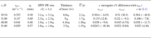


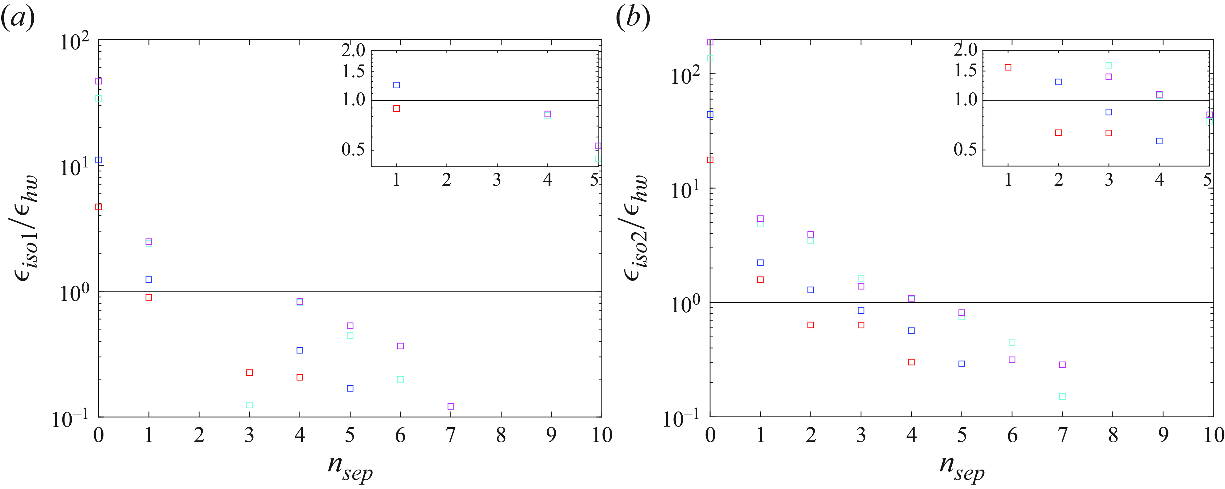


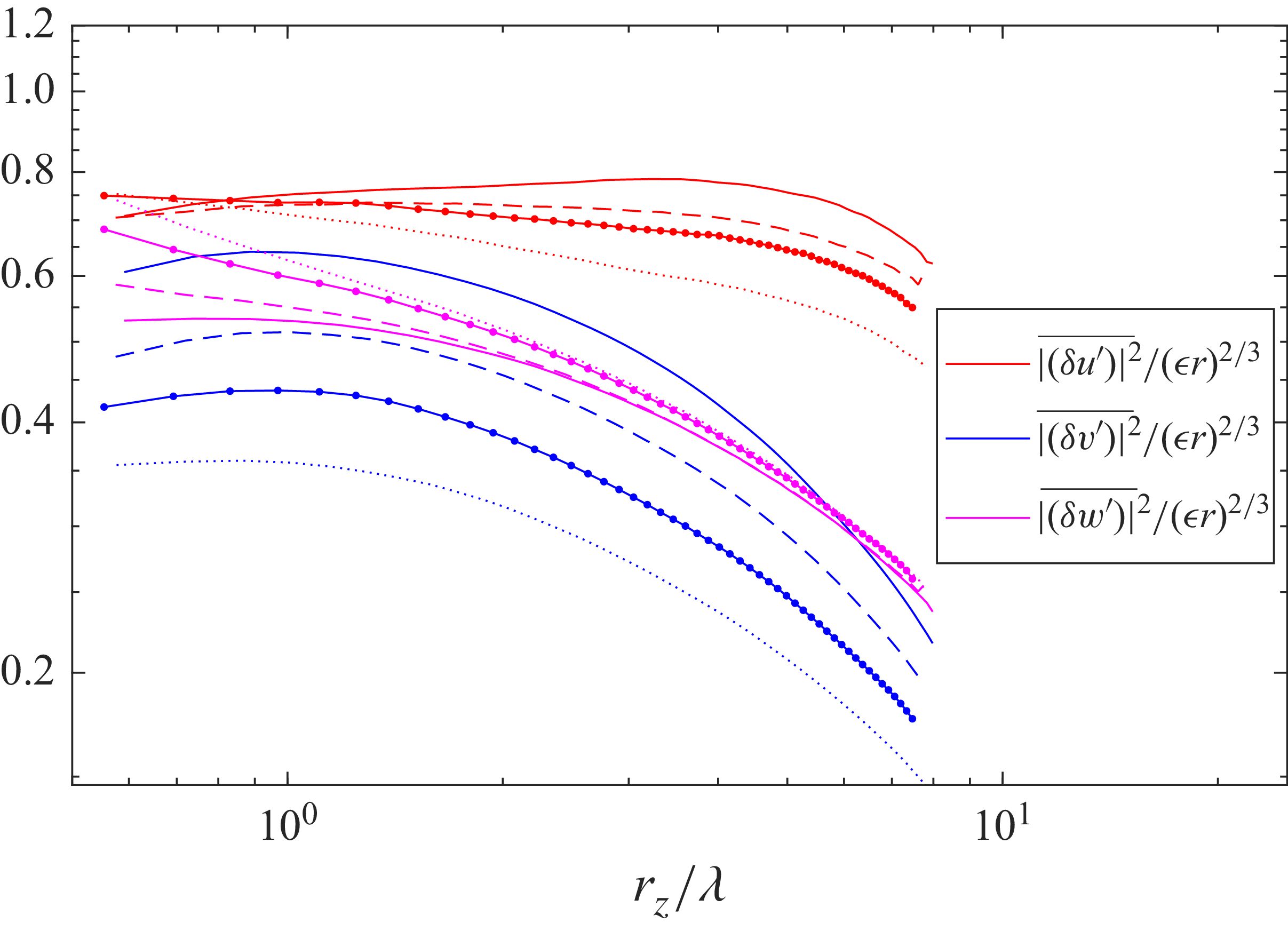


 Open access

