


1. Introduction
One key design consideration for offshore structures is the exciting force induced by surface gravity waves. In calm seas where wave amplitudes are small, linear potential flow theory suffices for predicting the dominant linear force. However, due to the nonlinear nature of wave–structure and wave–wave interactions, nonlinearities become increasingly important as the wave amplitude increases. While the super- and subharmonic nonlinear forces can excite high-frequency structural resonances in fixed or taut-moored structures (Huseby & Grue Reference Huseby and Grue2000; Jagdale et al. Reference Jagdale, Ma and Yan2022) and low-frequency motion responses of soft-moored floating structures (Coulling et al. Reference Coulling, Goupee, Robertson and Jonkman2013; Orszaghova et al. Reference Orszaghova, Taylor, Wolgamot, Madsen, Pegalajar-Jurado and Bredmose2021), respectively, wave-frequency forces are predicted sufficiently well by linear theory for most applications. Studies of nonlinear potential flow effects within the wave frequency range are therefore relatively scarce.
In this study, we provide substantial evidence of a nonlinear term known to manifest in the wave frequency range with third-order amplitude scaling. Such third-order first-harmonic loading terms are rarely addressed explicitly in the existing literature (Newman (Reference Newman1996) and Orszaghova et al. (Reference Orszaghova, Taylor, Wolgamot, Madsen, Pegalajar-Jurado and Bredmose2021) are examples) and existing third-order diffraction theories generally consider the superharmonic component only (Faltinsen et al. Reference Faltinsen, Newman and Vinje1995; Malenica & Molin Reference Malenica and Molin1995; Teng & Kato Reference Teng and Kato2002). However, for wave energy converters designed to resonate with incident waves, nonlinearities in the wave frequency range are of most interest. Improving our understanding of these effects should lead to more efficient designs and more accurate power capture estimation.
Numerous partially nonlinear studies have implicitly modelled some third-order first-harmonic terms within their total exciting forces (Ferri et al. Reference Ferri, Kramer and Pecher2013; Zurkinden et al. Reference Zurkinden, Ferri, Beatty, Kofoed and Kramer2013; Giorgi & Ringwood Reference Giorgi and Ringwood2017; Nielsen et al. Reference Nielsen2018), without explicitly separating individual harmonic terms. The present paper explores a simple example of this term in greater detail using both experimental and numerical results to confirm its properties and comment on its origin.
2. Experimental set-up
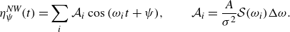
The experiments were conducted in the wave flume (see figure 1 for dimensions) at the Coastal and Offshore Research Laboratory, University of Western Australia. A HR Wallingford hinged wavemaker was used to generate unidirectional waves. An aluminium sphere, supported from above by a three-axis 50 N Interface load cell, was positioned along the longitudinal symmetry axis of the flume and close to the wavemaker, to maximise the time window prior to wave reflections from the beach, whilst far enough away to avoid evanescent waves. An Edinburgh Designs resistance wave gauge array was used to measure the wavefield. The instruments sampled data at 256 Hz or higher and were synchronised through an electronic trigger.
The incident waves were NewWave-type focused wave groups (Tromans et al. Reference Tromans, Anaturk and Hagemeijer1991; Taylor & Williams Reference Taylor and Williams2004) derived from a JONSWAP spectrum, with the first-harmonic (assumed linear) content given by
 \begin{equation} \eta ^{\textit{NW}}_{\psi }(t) = \sum _{i} \mathcal {A}_i \cos {(\omega _i t + \psi )}, \qquad \mathcal {A}_i = \frac {A}{\sigma ^2} \mathcal {S}(\omega _i) \Delta \omega . \end{equation}
Here, $\mathcal {A}_i$
is the amplitude of the
$\mathcal {A}_i$
is the amplitude of the $i{\mathrm {th}}$
angular frequency
$i{\mathrm {th}}$
angular frequency $\omega _i$
,
$\omega _i$
, $\psi$
is the focus phase,
$\psi$
is the focus phase, $A$
is the linear wave group amplitude at focus,
$A$
is the linear wave group amplitude at focus, $\sigma^2$
is the zeroth moment of the spectrum
$\sigma^2$
is the zeroth moment of the spectrum $\mathcal{S}$
and
$\mathcal{S}$
and $\Delta \omega$
is the angular frequency spacing. The focus time is assumed at
$\Delta \omega$
is the angular frequency spacing. The focus time is assumed at $t = 0$
. The input wave spectrum spans from
$t = 0$
. The input wave spectrum spans from $0$
to
$0$
to $2.5$
times the peak frequency
$2.5$
times the peak frequency $f_p$
. Six focus amplitudes, three peak periods, two phases at focus and five model drafts were tested, with select combinations excluded as the wave runup overtopped the sphere (see table 1).
$f_p$
. Six focus amplitudes, three peak periods, two phases at focus and five model drafts were tested, with select combinations excluded as the wave runup overtopped the sphere (see table 1). $(a)$
Elevation and
$(a)$
Elevation and $(b)$
plan view of the experimental set-up with key dimensions labelled. Corresponding photo in
$(b)$
plan view of the experimental set-up with key dimensions labelled. Corresponding photo in $(c)$
and short video (graphical abstract) linked.
$(c)$
and short video (graphical abstract) linked.
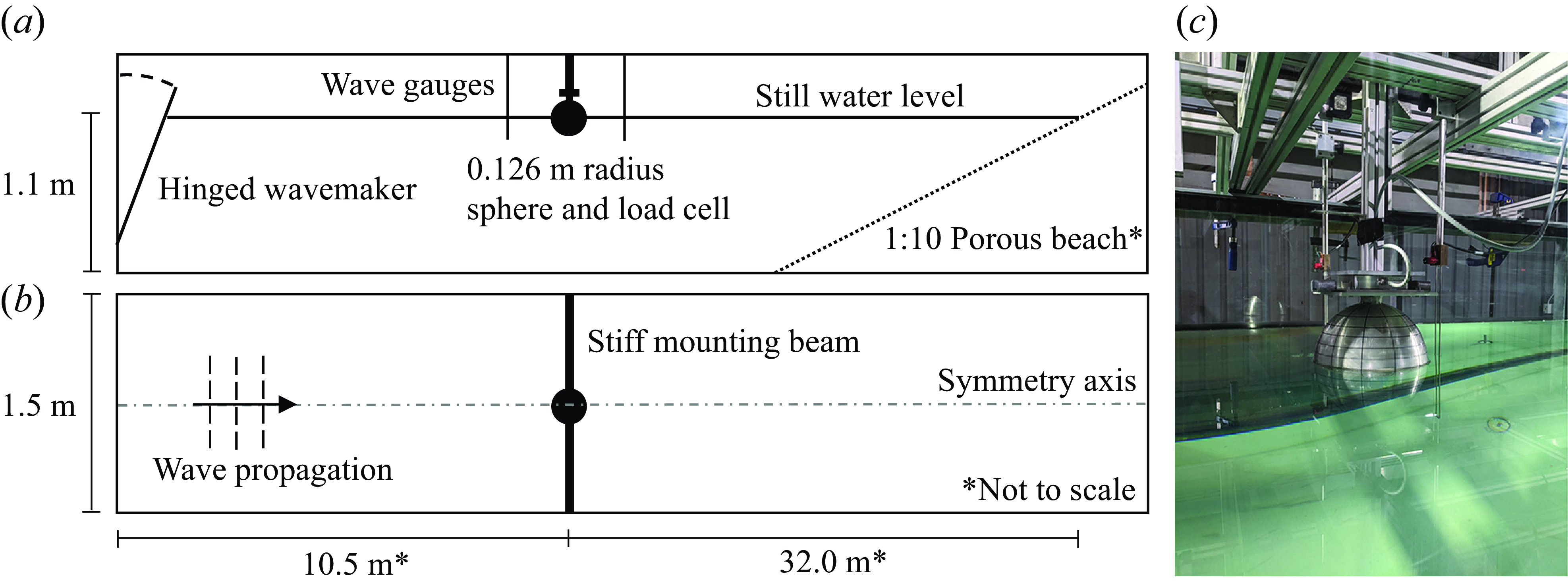
Nominal experimental parameters. Steepness values $k_pA$
correspond to
$k_pA$
correspond to $f_p = (0.40, 0.60, 0.80)$
Hz. Non-dimensional depth and radius are
$f_p = (0.40, 0.60, 0.80)$
Hz. Non-dimensional depth and radius are $k_p h = (0.95, 1.70, 2.85)$
and
$k_p h = (0.95, 1.70, 2.85)$
and $k_p R = (0.11, 0.19, 0.32)$
. Here,
$k_p R = (0.11, 0.19, 0.32)$
. Here, $d$
and
$d$
and $R$
denote the sphere draft and radius,
$R$
denote the sphere draft and radius, $h$
the water depth,
$h$
the water depth, $f$
and
$f$
and $k$
the wave frequency and wavenumber and
$k$
the wave frequency and wavenumber and $\Box _p$
the quantities at the peak frequency.
$\Box _p$
the quantities at the peak frequency.
Undisturbed wave tests were run in the absence of the model, with a wave gauge position corresponding to the sphere centre. All free surface data in this paper are from this wave gauge. A wave iteration technique (Stagonas et al. Reference Stagonas, Buldakov and Simons2014; Buldakov et al. Reference Buldakov, Stagonas and Simons2017) was used where necessary to achieve the desired first-harmonic components at focus as per (2.1), and second-order wave generation theory (Schäffer Reference Schäffer1996) employed to minimise second-order error waves. These steps were necessary to obtain demonstrably clean results (see Tan et al. (Reference Tan, Orszaghova, Kurniawan, Wolgamot and Todalshaug2023) for an earlier campaign). Note that all the raw experimental data used to produce the results in this paper are included as supplementary material (see data availability statement). This comprises synchronised time series of the total undisturbed free-surface elevation and the total heave force. Note that we define heave as positive upwards.
3. Harmonic structure and separation
Within potential flow theory, any weakly nonlinear response, e.g. the free-surface elevation, wave exciting force, can be decomposed into a Stokes expansion:
 \begin{equation} F(t) = F^{(11)} + F^{(20)} + F^{(22)} + F^{(31)} + F^{(33)} + \mathcal {O}(A^4), \end{equation}
where the superscripts in each term $F^{(mn)}$
represent the
$F^{(mn)}$
represent the $m{\mathrm {th}}$
order and the
$m{\mathrm {th}}$
order and the $n{\mathrm {th}}$
harmonic, i.e. a term that scales with
$n{\mathrm {th}}$
harmonic, i.e. a term that scales with $A^m$
and appears around
$A^m$
and appears around $n f_p$
in the frequency domain (see figure 6). Therefore,
$n f_p$
in the frequency domain (see figure 6). Therefore, $F^{(11)}$
is simply the first-order first-harmonic (linear term) and
$F^{(11)}$
is simply the first-order first-harmonic (linear term) and $F^{(31)}$
is the third-order first-harmonic which arises due to
$F^{(31)}$
is the third-order first-harmonic which arises due to $(++-)$
interactions of triplets of components. For an incident wave specified in (2.1), this third-order force has the form
$(++-)$
interactions of triplets of components. For an incident wave specified in (2.1), this third-order force has the form
 \begin{equation} F^{(31)}(t) = \sum _i \sum _j \sum _k \mathcal {A}_i \mathcal {A}_j \mathcal {A}_k \left |\mathcal {F}^{(31)}\right | \cos {\left ((\omega _{i} + \omega _{j} - \omega _{k})t + \psi + \arg {\left (\mathcal {F}^{(31)}\right )}\right )}, \end{equation}
where $\mathcal {F}^{(31)}(\omega _i, \omega _j, \omega _k)$
is the corresponding third-order first-harmonic wave-to-force complex transfer function (TF).
$\mathcal {F}^{(31)}(\omega _i, \omega _j, \omega _k)$
is the corresponding third-order first-harmonic wave-to-force complex transfer function (TF).
For broad-banded incident waves, harmonic separation can be achieved using phase-based techniques which combine different phase realisations to extract certain terms (Fitzgerald et al. Reference Fitzgerald, Taylor, Eatock Taylor, Grice and Zang2014). We use two-phase harmonic separation to firstly isolate the odd harmonics:
 \begin{equation} F_{odd}(t) = \frac {1}{2}\left (F_{\pi /2} - F_{3\pi /2}\right ) = F^{(11)} + F^{(31)} + F^{(33)} + \mathcal {O}(A^5), \end{equation}
where $F_{\pi /2}$
and
$F_{\pi /2}$
and $F_{3\pi /2}$
are the resulting forces from up- and down-crossing incident wave groups
$F_{3\pi /2}$
are the resulting forces from up- and down-crossing incident wave groups $\eta ^{\textit{NW}}_{\pi /2}$
and
$\eta ^{\textit{NW}}_{\pi /2}$
and $\eta ^{\textit{NW}}_{3\pi /2}$
. A low-pass filter removes
$\eta ^{\textit{NW}}_{3\pi /2}$
. A low-pass filter removes $F^{(33)}$
, leaving only
$F^{(33)}$
, leaving only $F^{(11)} + F^{(31)}$
in the wave frequency range. These phase-based techniques alone are, however, unable to further separate
$F^{(11)} + F^{(31)}$
in the wave frequency range. These phase-based techniques alone are, however, unable to further separate $F^{(11)}$
and
$F^{(11)}$
and $F^{(31)}$
due to their identical phase dependence, no matter how many phases are used. However, the initial inseparability of these two first-harmonic terms is key to interpreting the results of this study.
$F^{(31)}$
due to their identical phase dependence, no matter how many phases are used. However, the initial inseparability of these two first-harmonic terms is key to interpreting the results of this study.
Theoretically, one could simply subtract a numerically calculated $F^{(11)}$
from an experimental
$F^{(11)}$
from an experimental $F^{(11)} + F^{(31)}$
to isolate
$F^{(11)} + F^{(31)}$
to isolate $F^{(31)}$
, but this can produce unreliable results due to small errors between the experimentally measured waves and forces. Even these small errors are substantial when subtracting two large signals to find a small residual. Therefore, most of the following analysis utilises the TF moduli which are less sensitive to these errors (but the phases are also important in more general cases). We then use the TFs to derive an experimental linear force for this purpose.
$F^{(31)}$
, but this can produce unreliable results due to small errors between the experimentally measured waves and forces. Even these small errors are substantial when subtracting two large signals to find a small residual. Therefore, most of the following analysis utilises the TF moduli which are less sensitive to these errors (but the phases are also important in more general cases). We then use the TFs to derive an experimental linear force for this purpose.
4. Experimental results
We first present results for the hemispherical draft ( $d/R = 1.0$
) in the longest waves (
$d/R = 1.0$
) in the longest waves ( $k_p R = 0.11$
). The first-harmonic undisturbed wave
$k_p R = 0.11$
). The first-harmonic undisturbed wave $\eta ^{(11)} + \eta ^{(31)}$
and heave exciting force
$\eta ^{(11)} + \eta ^{(31)}$
and heave exciting force $F^{(11)} + F^{(31)}$
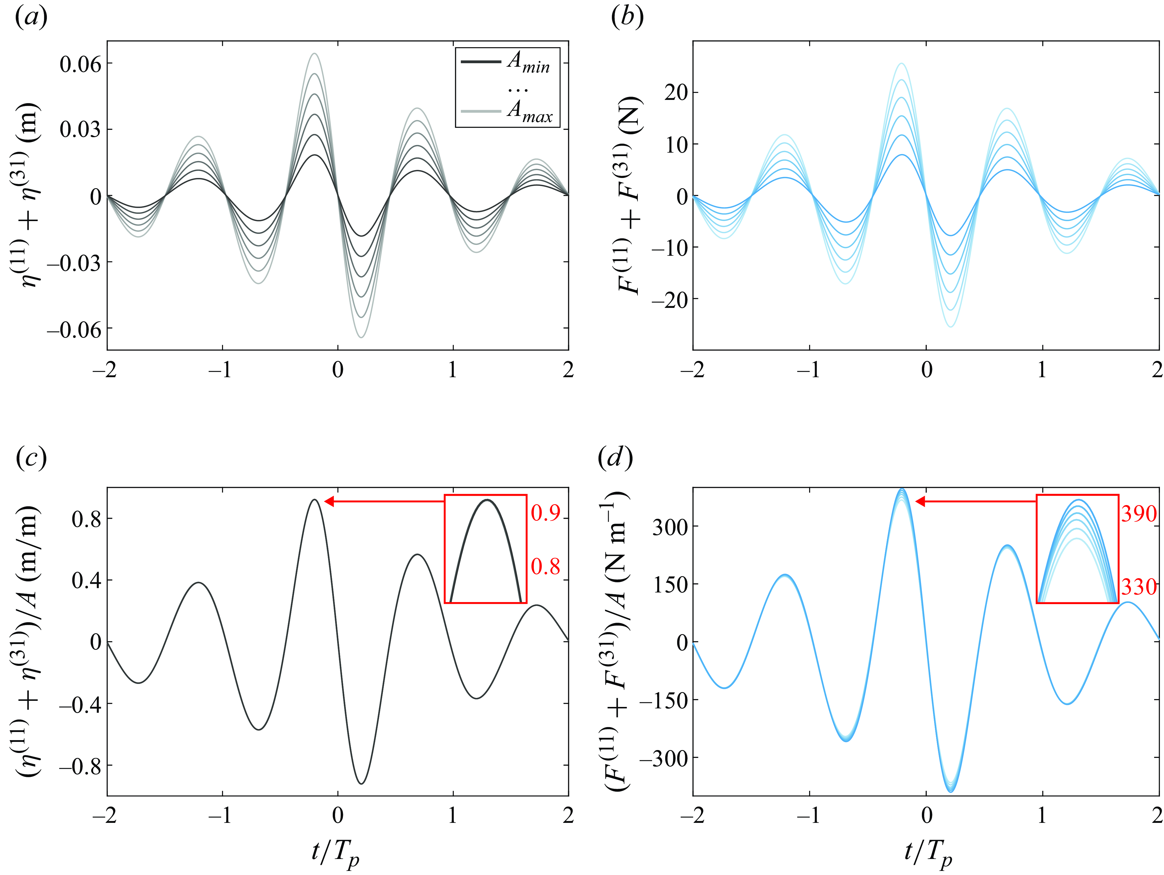
time series are plotted in figure 2. The six amplitudes tested are shown in both raw and amplitude-normalised forms, where the normalisation is performed using the peaks of the first-harmonic wave envelopes,
$F^{(11)} + F^{(31)}$
time series are plotted in figure 2. The six amplitudes tested are shown in both raw and amplitude-normalised forms, where the normalisation is performed using the peaks of the first-harmonic wave envelopes, $A$
, all of which are within 1% of the nominal values.
$A$
, all of which are within 1% of the nominal values.
While the waves collapse under this first-order normalisation, the heave forces exhibit noticeable amplitude separation such that the first-harmonic force scales slightly less than linearly. This ordered amplitude separation suggests that nonlinear contributions are present. The phase, however, seems to be largely unaffected. To further investigate this, we form the first-harmonic wave-to-force TFs:
 \begin{equation} \mathcal {F}^{(1)}(\omega ) \approx \frac {\hat {F}^{(11)} + \hat {F}^{(31)}}{\hat {\eta }^{(11)} + \hat {\eta }^{(31)}} = \frac {\hat {F}^{(11)}}{\hat {\eta }^{(11)}} + \mathcal {O}(A^2), \end{equation}
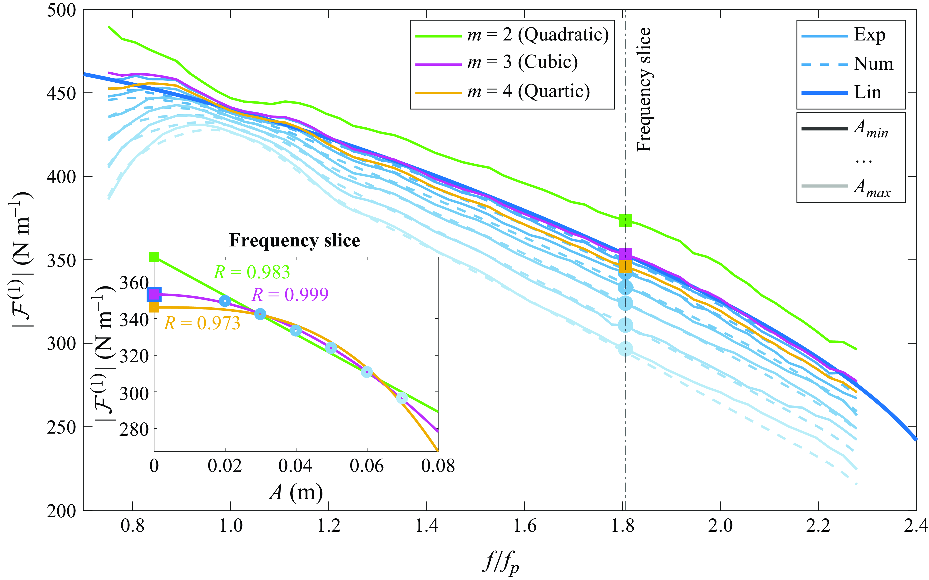
where the ‘hat’ represents the equivalent quantity as a complex amplitude. The TF moduli are plotted in figure 3 to examine the amplitude scaling across the linear frequency range. The experimental results are plotted in thin blue lines while the bold blue line shows the result from linear theory (other graphical features are introduced later). In this form, the amplitude separation is far more apparent and shows a characteristic feature where the separation is minimised around the peak frequency and increases towards the tails of the spectrum. This is indicative of nonlinear terms which possess broader bandwidths as a result of sum- and difference-frequency interactions (a well-known property of broad-banded nonlinear terms sometimes referred to as ‘spectral smearing’; Fitzgerald et al. Reference Fitzgerald, Taylor, Eatock Taylor, Grice and Zang2014). As such, the linear term dominates around the peak wave frequency with minimal influence of the nonlinear terms, whereas the relative contributions of the nonlinear terms increase towards the tails of the spectrum, where the linear term subsides more rapidly (see figure 6). We also highlight the utility of broad-banded wave groups, as this defining feature would not be apparent in monochromatic waves.
While not shown here for brevity, the amplitude-normalised first-harmonic paddle motion signals (used to generate the incident long-wave groups) collapse linearly to within 0.7 % of each other at the peak (similarly to the undisturbed waves which show 0.2 % separation, while the force separations are up to 8 %). This suggests that no significant spectral evolution occurs between the paddle and model locations and that $\eta ^{(31)}$
, arising from nonlinear wave–wave interactions (Madsen & Fuhrman Reference Madsen and Fuhrman2012), is negligible, consistent with expectations in these low-steepness conditions (
$\eta ^{(31)}$
, arising from nonlinear wave–wave interactions (Madsen & Fuhrman Reference Madsen and Fuhrman2012), is negligible, consistent with expectations in these low-steepness conditions ( $k_pA = [0.017, \ldots ,0.061]$
). We also approximate the theoretical
$k_pA = [0.017, \ldots ,0.061]$
). We also approximate the theoretical $\eta ^{(31)}$
in these conditions using the Stokes wave coefficient and narrow-banded approximation (Walker et al. Reference Walker, Taylor and Eatock Taylor2004; Zhao & Liu Reference Zhao and Liu2022) which shows that the magnitude of
$\eta ^{(31)}$
in these conditions using the Stokes wave coefficient and narrow-banded approximation (Walker et al. Reference Walker, Taylor and Eatock Taylor2004; Zhao & Liu Reference Zhao and Liu2022) which shows that the magnitude of $\eta ^{(31)}$
is less than 1 % of
$\eta ^{(31)}$
is less than 1 % of $\eta ^{(11)}$
and is therefore neglected in the subsequent analysis. Referring back to (4.1), the nonlinear behaviour in the first-harmonic TFs therefore appears to be largely a result of the nonlinear first-harmonic force
$\eta ^{(11)}$
and is therefore neglected in the subsequent analysis. Referring back to (4.1), the nonlinear behaviour in the first-harmonic TFs therefore appears to be largely a result of the nonlinear first-harmonic force $F^{(31)}$
rather than nonlinearities in the wave.
$F^{(31)}$
rather than nonlinearities in the wave.
Raw (a,b) and normalised (c,d) first-harmonic incident waves (a,c) and heave exciting forces (b,d). Darker lines are smaller-amplitude tests.
First-harmonic TF moduli for a hemisphere ( $d/R = 1.0$
) in long waves (
$d/R = 1.0$
) in long waves ( $k_pR = 0.11$
). Thin solid blue lines are experimental first-harmonic TFs derived from data in figure 2. The bold solid blue line is the linear TF calculated by WAMIT (2020). Green, magenta and orange lines are experimentally extrapolated linear TFs for
$k_pR = 0.11$
). Thin solid blue lines are experimental first-harmonic TFs derived from data in figure 2. The bold solid blue line is the linear TF calculated by WAMIT (2020). Green, magenta and orange lines are experimentally extrapolated linear TFs for $A\rightarrow 0$
from second-, third- and fourth-order amplitude scaling, respectively. Thin dashed blue lines are the modelled first-harmonic TFs using the small-body approximation equation (5.3). The inset plot shows the fitting procedure at the frequency slice denoted by the dash-dotted black vertical line. The coefficient of determination (
$A\rightarrow 0$
from second-, third- and fourth-order amplitude scaling, respectively. Thin dashed blue lines are the modelled first-harmonic TFs using the small-body approximation equation (5.3). The inset plot shows the fitting procedure at the frequency slice denoted by the dash-dotted black vertical line. The coefficient of determination ( $\mathrm{R}^2$
) is given in the inset plot for each fit.
$\mathrm{R}^2$
) is given in the inset plot for each fit.
The amplitude scaling of these nonlinear first-harmonic forces should be cubic if they are truly third-order terms. If we consider the first harmonic as a sum of the linear force and a nonlinear force of an undetermined order $m$
, then the TFs adopt the form
$m$
, then the TFs adopt the form
 \begin{equation} \mathcal {F}^{(1)}(\omega ) \approx \frac {\hat {F}^{(11)} + \hat {F}^{(m1)}}{\hat {\eta }^{(11)}} = \mathcal {F}^{(11)} + \mathcal {F}^{(m1)}_{\textit{flat}} \left (\hat {\eta }^{(11)}\right )^{m-1}, \end{equation}
where $\mathcal {F}^{(11)}$
is the linear wave-to-force TF and
$\mathcal {F}^{(11)}$
is the linear wave-to-force TF and $\mathcal {F}_{\textit{flat}}^{(m1)}$
is the so-called quasi-TF or flat nonlinear TF (Taylor et al. Reference Taylor, Zang, Walker and Eatock Taylor2007; Grice et al. Reference Grice, Taylor, Eatock Taylor, Zang and Walker2015; Zhao et al. Reference Zhao, Taylor, Wolgamot and Eatock Taylor2021) which is a one-dimensional approximation of the full
$\mathcal {F}_{\textit{flat}}^{(m1)}$
is the so-called quasi-TF or flat nonlinear TF (Taylor et al. Reference Taylor, Zang, Walker and Eatock Taylor2007; Grice et al. Reference Grice, Taylor, Eatock Taylor, Zang and Walker2015; Zhao et al. Reference Zhao, Taylor, Wolgamot and Eatock Taylor2021) which is a one-dimensional approximation of the full $m$
-dimensional quantity
$m$
-dimensional quantity $\mathcal {F}^{(m1)}$
. For example, for the third-order first-harmonic TF,
$\mathcal {F}^{(m1)}$
. For example, for the third-order first-harmonic TF,
 \begin{equation} \mathcal {F}^{(31)}(\omega _i, \omega _j, \omega _k) \approx \mathcal {F}_{\textit{flat}}^{(31)} (\omega _{i+j-k}), \end{equation}
where $\mathcal {F}_{\textit{flat}}^{(31)}$
is a function of a single frequency – the output
$\mathcal {F}_{\textit{flat}}^{(31)}$
is a function of a single frequency – the output $(++-)$
frequency
$(++-)$
frequency $\omega _{i+j-k}$
which spans the linear-wave frequency range and beyond due to spectral smearing discussed above.
$\omega _{i+j-k}$
which spans the linear-wave frequency range and beyond due to spectral smearing discussed above.
Therefore by fitting (4.2) for a given $m$
to the experimentally obtained TFs, we can determine the order of the dominant nonlinear contribution. In general, this can be done by fitting complex coefficients
$m$
to the experimentally obtained TFs, we can determine the order of the dominant nonlinear contribution. In general, this can be done by fitting complex coefficients $\mathcal {F}^{(11)}$
and
$\mathcal {F}^{(11)}$
and $\mathcal {F}^{(m1)}_{\textit{flat}}$
with the available experimental
$\mathcal {F}^{(m1)}_{\textit{flat}}$
with the available experimental $\mathcal {F}^{(1)}$
and
$\mathcal {F}^{(1)}$
and $\hat {\eta }^{(11)}$
. However, in our case where the nonlinear term simply appears to be in antiphase with the linear term, as seen in figure 2, we can reduce the number of fitting degrees of freedom to obtain more definitive fits. This is done by using the TF moduli,
$\hat {\eta }^{(11)}$
. However, in our case where the nonlinear term simply appears to be in antiphase with the linear term, as seen in figure 2, we can reduce the number of fitting degrees of freedom to obtain more definitive fits. This is done by using the TF moduli,
 \begin{equation} \left |\mathcal {F}^{(1)}(\omega )\right | = \left |\mathcal {F}^{(11)} + \mathcal {F}^{(m1)}_{\textit{flat}} \left (\hat {\eta }^{(11)}\right )^{m-1}\right |, \end{equation}
which can be expanded through standard complex arithmetic,
 \begin{equation} \left |\mathcal {F}^{(1)}(\omega )\right | = \sqrt {\left |\mathcal {F}^{(11)}\right |^2 + \left |\mathcal {F}^{(m1)}_{\textit{flat}}\left (\hat {\eta }^{(11)}\right )^{m-1}\right |^2 + 2\left |\mathcal {F}^{(11)}\right |\left |\mathcal {F}^{(m1)}_{\textit{flat}}\right |\left |\left (\hat {\eta }^{(11)}\right )^{m-1}\right | \cos {\Delta \theta }}. \end{equation}
Taking $\Delta \theta = \pi$
, the phase difference between
$\Delta \theta = \pi$
, the phase difference between $\mathcal {F}^{(11)}$
and
$\mathcal {F}^{(11)}$
and $\mathcal {F}^{(m1)}_{\textit{flat}}$
, recognising
$\mathcal {F}^{(m1)}_{\textit{flat}}$
, recognising $\left |\hat {\eta }^{(11)}\right | \propto A$
and utilising a perfect square, the expression simplifies to
$\left |\hat {\eta }^{(11)}\right | \propto A$
and utilising a perfect square, the expression simplifies to
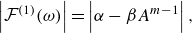 \begin{equation} \left |\mathcal {F}^{(1)}(\omega )\right | = \left |\alpha - \beta A^{m-1}\right |, \end{equation}
where $\alpha = |\mathcal {F}^{(11)}|$
and
$\alpha = |\mathcal {F}^{(11)}|$
and $\beta$
is a real positive coefficient.
$\beta$
is a real positive coefficient.
Consider the TF moduli at a given frequency slice. The inset plot in figure 3 shows an example at $1.8f_p$
, where
$1.8f_p$
, where $|\mathcal {F}^{(1)}|$
is plotted as a function of
$|\mathcal {F}^{(1)}|$
is plotted as a function of $A$
. Three fits are shown, for
$A$
. Three fits are shown, for $m = 2,3,4$
. The
$m = 2,3,4$
. The $y$
-axis intercept, i.e. the fitted value of
$y$
-axis intercept, i.e. the fitted value of $\alpha$
, is the modulus of the experimentally derived linear TF,
$\alpha$
, is the modulus of the experimentally derived linear TF, $|\mathcal {F}^{(11)}|$
. This procedure is then repeated across the entire first-harmonic frequency range and results are shown in the green, magenta and orange lines of the main plot. Clearly, the experimental linear TF assuming third-order scaling is the best fit and appears to agree very well with the numerical linear TF, confirming that the observed nonlinear features are due to third-order effects.
$|\mathcal {F}^{(11)}|$
. This procedure is then repeated across the entire first-harmonic frequency range and results are shown in the green, magenta and orange lines of the main plot. Clearly, the experimental linear TF assuming third-order scaling is the best fit and appears to agree very well with the numerical linear TF, confirming that the observed nonlinear features are due to third-order effects.
The Morison-type drag force also manifests in the wave frequency range (Molin Reference Molin2023) and therefore could affect the first-harmonic TFs. In the long-wave limit, $F^{(11)}$
reduces to buoyancy, which is proportional to
$F^{(11)}$
reduces to buoyancy, which is proportional to $\eta ^{(11)}$
. On the other hand, vertical components of the drag force (in the wave frequency range) largely follow the phasing of vertical fluid velocity and exhibit a
$\eta ^{(11)}$
. On the other hand, vertical components of the drag force (in the wave frequency range) largely follow the phasing of vertical fluid velocity and exhibit a $\pi /2$
phase shift relative to
$\pi /2$
phase shift relative to $F^{(11)}$
. This results in an increase of the TF modulus, as adding a signal in quadrature increases the resultant amplitude. However, this is clearly not the case for the observed data. We thus find strong evidence that the observed nonlinear effects are in fact due to third-order first-harmonic force components. Furthermore, this method derives an experimental
$F^{(11)}$
. This results in an increase of the TF modulus, as adding a signal in quadrature increases the resultant amplitude. However, this is clearly not the case for the observed data. We thus find strong evidence that the observed nonlinear effects are in fact due to third-order first-harmonic force components. Furthermore, this method derives an experimental $F^{(11)}$
, which can be subtracted from
$F^{(11)}$
, which can be subtracted from $F^{(11)} + F^{(31)}$
to isolate
$F^{(11)} + F^{(31)}$
to isolate $F^{(31)}$
, shown in figure 6. We believe this is the first time this has been accurately and robustly achieved.
$F^{(31)}$
, shown in figure 6. We believe this is the first time this has been accurately and robustly achieved.
5. Small-body approximation
5.1. Comparison with experiments
To model the third-order first-harmonic forces, we start with the classical linear small-body (SB) approximation (Newman Reference Newman2017a ; Falnes & Kurniawan Reference Falnes and Kurniawan2020), according to which the heave exciting force, in the frequency domain, becomes
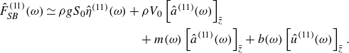 \begin{align} \hat {F}^{(11)}_{\textit{SB}}(\omega ) \simeq \rho g S_0 \hat {\eta }^{(11)}(\omega ) & + \rho V_0 \left[\hat {a}^{(11)}(\omega )\right]_{\bar {z}} \nonumber \\ & \quad + m(\omega ) \left[\hat {a}^{(11)}(\omega )\right]_{\bar {z}} + b(\omega )\left[\hat {u}^{(11)}(\omega )\right]_{\bar {z}}. \end{align}
This can be rewritten in the time domain as
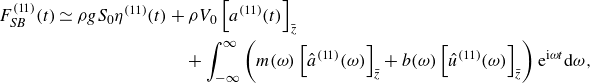 \begin{align} F^{(11)}_{\textit{SB}}(t) \simeq \rho g S_0 \eta ^{(11)}(t) & + \rho V_0 \left[a^{(11)}(t)\right]_{\bar {z}} \nonumber \\ & \quad + \int _{-\infty }^{\infty } \left (m(\omega )\left[\hat {a}^{(11)}(\omega )\right]_{\bar {z}} + b(\omega )\left[\hat {u}^{(11)}(\omega )\right]_{\bar {z}}\right ) \mathrm {e}^{\mathrm {i} \omega t} \mathrm {d}\omega ,\end{align}
where $\rho$
is the water density,
$\rho$
is the water density, $g$
the gravitational acceleration,
$g$
the gravitational acceleration, $S_0$
and
$S_0$
and $V_0$
the equilibrium waterplane area and submerged volume,
$V_0$
the equilibrium waterplane area and submerged volume, $a^{(11)}$
and
$a^{(11)}$
and $u^{(11)}$
the linear fluid vertical accelerations and velocities,
$u^{(11)}$
the linear fluid vertical accelerations and velocities, $m$
and
$m$
and $b$
the vertical added mass and radiation damping coefficients and
$b$
the vertical added mass and radiation damping coefficients and $[\dots ]_{\bar {z}}$
indicates the fluid kinematics evaluated at a chosen representative spatial point. For an axisymmetric body, the inherent horizontal reference coordinate lies on the vertical axis of rotational symmetry, while a natural choice for the vertical coordinate is the centroid
$[\dots ]_{\bar {z}}$
indicates the fluid kinematics evaluated at a chosen representative spatial point. For an axisymmetric body, the inherent horizontal reference coordinate lies on the vertical axis of rotational symmetry, while a natural choice for the vertical coordinate is the centroid $\bar {z}$
calculated from
$\bar {z}$
calculated from $V_0$
. While the diffraction forces (third and fourth terms in (5.1) and (5.2)) are approximated in different forms depending on the strictness of the SB assumptions (e.g. some authors forgo radiation damping terms but others retain them), only the Froude–Krylov forces (the first and second terms) are necessary to model the behaviour of interest, so any appropriate form of the diffraction force will suffice.
$V_0$
. While the diffraction forces (third and fourth terms in (5.1) and (5.2)) are approximated in different forms depending on the strictness of the SB assumptions (e.g. some authors forgo radiation damping terms but others retain them), only the Froude–Krylov forces (the first and second terms) are necessary to model the behaviour of interest, so any appropriate form of the diffraction force will suffice.
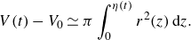
The first term is the linearised excess buoyancy force, which we rewrite in a nonlinear form as $\rho g (V(t) - V_0 )$
using the instantaneous submerged volume
$\rho g (V(t) - V_0 )$
using the instantaneous submerged volume $V(t)$
. For consistency,
$V(t)$
. For consistency, $V_0$
in the second term is also replaced with
$V_0$
in the second term is also replaced with $V(t)$
. The nonlinear SB model is then
$V(t)$
. The nonlinear SB model is then
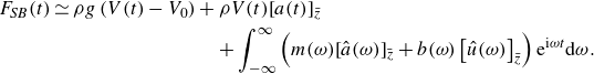 \begin{align} F_{\textit{SB}}(t) \simeq \rho g \left (V(t) - V_0\right ) & + \rho V(t) [a(t)]_{\bar {z}} \nonumber \\ & \quad + \int _{-\infty }^{\infty } \left (m(\omega )[\hat {a}(\omega )]_{\bar {z}} + b(\omega )\left[\hat {u}(\omega )\right]_{\bar {z}}\right ) \mathrm {e}^{\mathrm {i} \omega t} \mathrm {d}\omega . \end{align}
Much of the observed nonlinear features in the first-harmonic forces can be successfully modelled using (5.3), with $V(t)$
calculated as per (5.4) using the undisturbed first-harmonic waves, i.e.
$V(t)$
calculated as per (5.4) using the undisturbed first-harmonic waves, i.e. $\eta \rightarrow \eta ^{(11)}$
, and with linear theory used for
$\eta \rightarrow \eta ^{(11)}$
, and with linear theory used for $a(t), \hat {a}(\omega ), \hat {u}(\omega )$
. However, to improve modelling of the second-order forces (see figure 6), second-order incident wave quantities are modelled according to Dalzell (Reference Dalzell1999), i.e.
$a(t), \hat {a}(\omega ), \hat {u}(\omega )$
. However, to improve modelling of the second-order forces (see figure 6), second-order incident wave quantities are modelled according to Dalzell (Reference Dalzell1999), i.e. $\eta \rightarrow \eta ^{(11)} + \eta ^{(20)} + \eta ^{(22)}$
and similarly for the kinematics. Then
$\eta \rightarrow \eta ^{(11)} + \eta ^{(20)} + \eta ^{(22)}$
and similarly for the kinematics. Then $F_{\textit{SB}}(t)$
is processed identically to the experimental
$F_{\textit{SB}}(t)$
is processed identically to the experimental $F(t)$
to obtain numerical first-harmonic TFs, plotted with dashed lines in figure 3.
$F(t)$
to obtain numerical first-harmonic TFs, plotted with dashed lines in figure 3.
The SB approximation evidently captures the amplitude separation features very accurately. To understand why these simple volumetric corrections are so effective, we first consider the relative size of the Froude–Krylov terms in (5.3). Under the tested low-steepness wave conditions, $a$
is significantly smaller than
$a$
is significantly smaller than $g$
, and buoyancy is dominant. Since buoyancy solely depends on
$g$
, and buoyancy is dominant. Since buoyancy solely depends on $V(t)$
, we further investigate this by assuming that
$V(t)$
, we further investigate this by assuming that $\eta$
is flat across the body (consistent with the SB assumptions and valid for
$\eta$
is flat across the body (consistent with the SB assumptions and valid for $k_pR = 0.11$
). The instantaneous submerged geometry is then a spherical cap whose volume adopts the simple algebraic form
$k_pR = 0.11$
). The instantaneous submerged geometry is then a spherical cap whose volume adopts the simple algebraic form
 \begin{equation} V(t) \simeq \frac {1}{3} \pi \left (2R^3 + 3R^2\eta (t) - \eta ^3(t) \right ), \end{equation}
where the constant first term is the equilibrium submerged volume, $V_0$
. This approximate form clearly demonstrates that the instantaneous volume, and by extension the buoyancy force, has third-order dependency on the wave elevation in antiphase with the first-order dependency, exactly as the experimental results have shown.
$V_0$
. This approximate form clearly demonstrates that the instantaneous volume, and by extension the buoyancy force, has third-order dependency on the wave elevation in antiphase with the first-order dependency, exactly as the experimental results have shown.
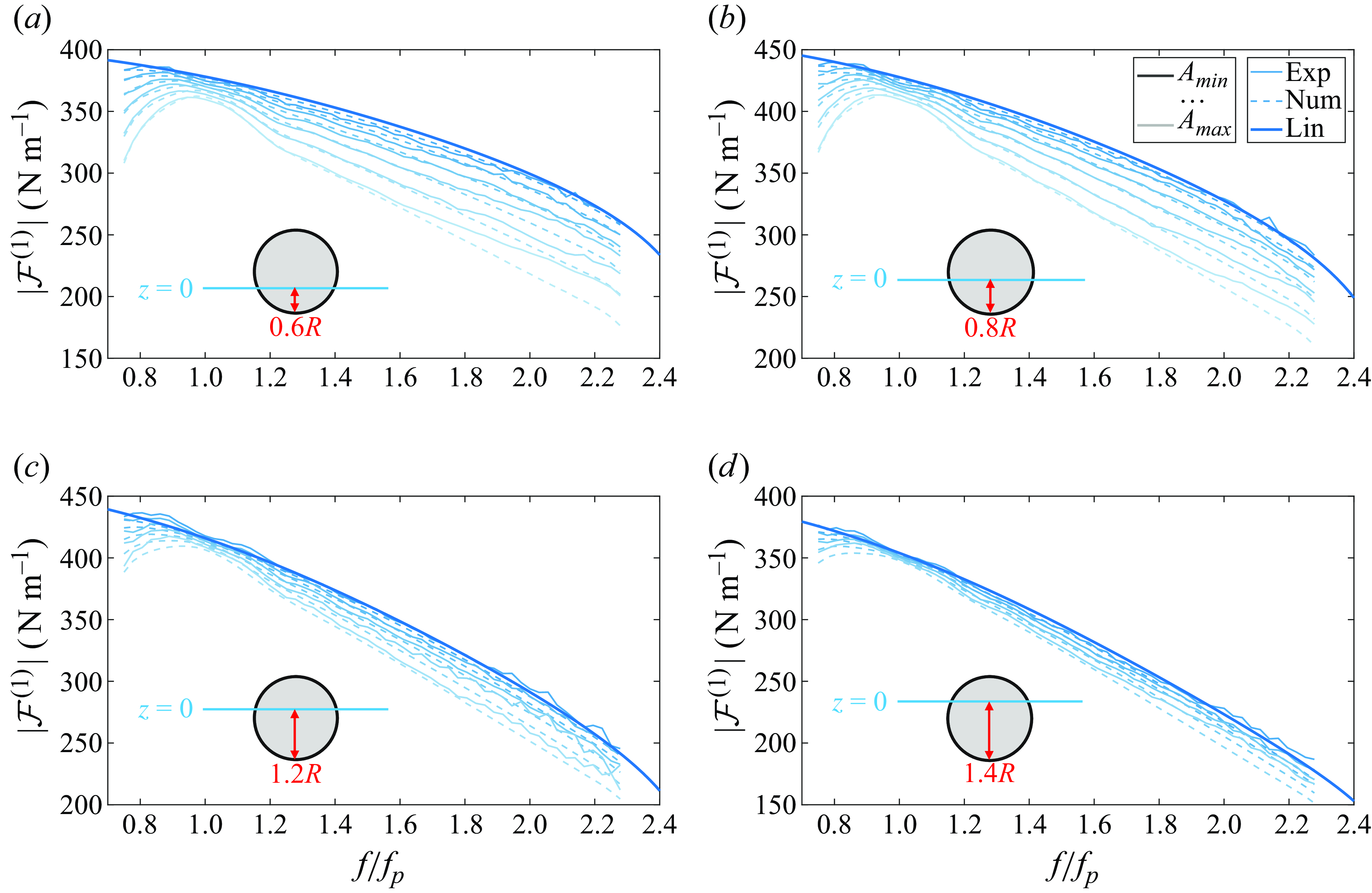
We now introduce results for other drafts of the sphere and plot the experimental and numerical first-harmonic TFs in figure 4. The amplitude separations at these drafts are also modelled relatively well, with some discrepancies at the end of the high-frequency tail, but nevertheless reproducing the correct behaviour between drafts. Since the linear coordinate transformation $\eta (t) \rightarrow \eta (t) + d - R$
can be used in (5.4) for a sphere at an arbitrary draft, the above discussion for the hemisphere and the efficacy of the SB model apply to these drafts also. Therefore
$\eta (t) \rightarrow \eta (t) + d - R$
can be used in (5.4) for a sphere at an arbitrary draft, the above discussion for the hemisphere and the efficacy of the SB model apply to these drafts also. Therefore $F^{(31)}$
is in antiphase with
$F^{(31)}$
is in antiphase with $F^{(11)}$
at any draft, in long waves.
$F^{(11)}$
at any draft, in long waves.
First-harmonic TF moduli extracted from experiments (thin solid) and calculated from the SB numerical model (thin dashed) for non-hemispherical geometry cases. The graphic in each subplot shows the equilibrium draft of the sphere.
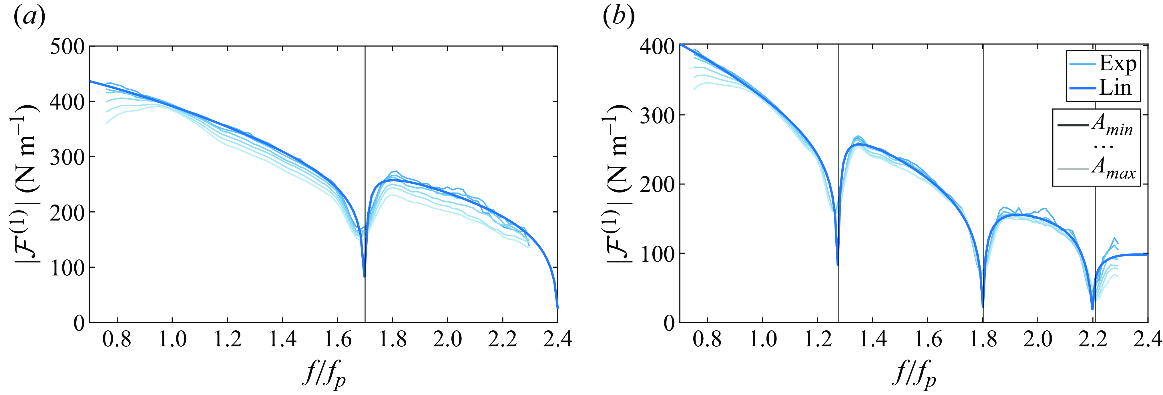
Experimental (thin solid) first-harmonic TF moduli for the hemisphere in the intermediate-wave (a) and short-wave (b) conditions. Vertical black lines mark cross-mode frequencies of the wave flume. Note that in these conditions, the iterated wave paddle motions (prior to inclusion of second-order wave generation signals) do not scale linearly with $A$
, indicating wavefield evolution between the paddle and model locations.
$A$
, indicating wavefield evolution between the paddle and model locations.
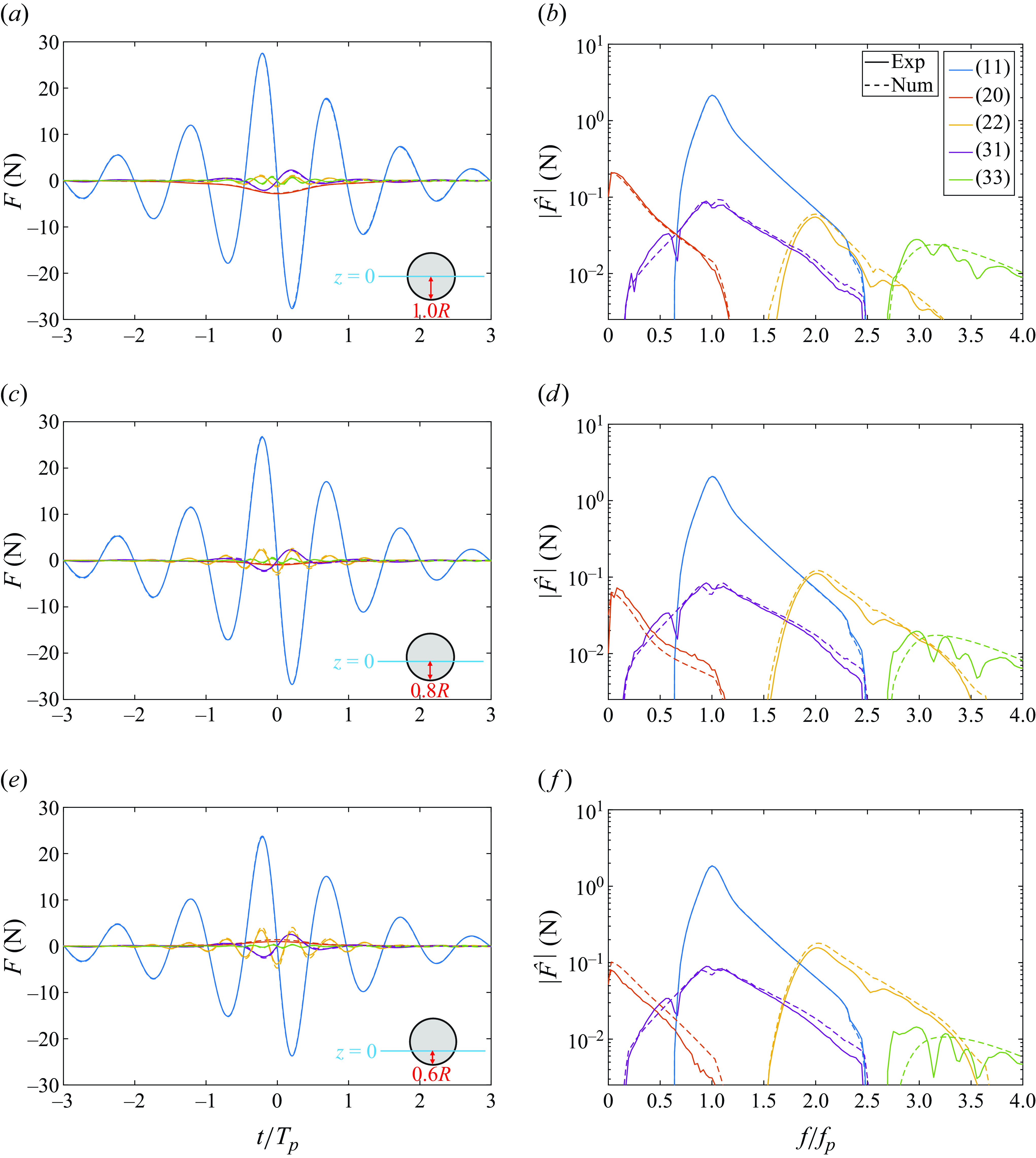
Experimentally measured (solid) and numerically modelled (dashed) heave exciting force harmonics in the time (a,c,e) and frequency (b,d,f) domains induced by wave groups of $k_p A = 0.061$
and
$k_p A = 0.061$
and $k_p R = 0.11$
. The graphic in each row shows the equilibrium draft of the sphere. Band-pass-filtered regions for each harmonic are
$k_p R = 0.11$
. The graphic in each row shows the equilibrium draft of the sphere. Band-pass-filtered regions for each harmonic are $[0.60, 2.50] f_p$
for
$[0.60, 2.50] f_p$
for $(11)$
,
$(11)$
, $[0, 1.20] f_p$
for
$[0, 1.20] f_p$
for $(20)$
,
$(20)$
, $[1.45, 3.70] f_p$
for
$[1.45, 3.70] f_p$
for $(22)$
,
$(22)$
, $[0.10, 2.55] f_p$
for
$[0.10, 2.55] f_p$
for $(31)$
and
$(31)$
and $[2.65, 4.80] f_p$
for
$[2.65, 4.80] f_p$
for $(33)$
.
$(33)$
.
In short waves ( $k_pR = 0.32$
), the experimental TF moduli seen in figure 5(b) indicate that linear theory appears to be largely sufficient for accurate predictions of the first-harmonic heave force. The TF phase, which is not shown here, also has little deviation. The intermediate waves (
$k_pR = 0.32$
), the experimental TF moduli seen in figure 5(b) indicate that linear theory appears to be largely sufficient for accurate predictions of the first-harmonic heave force. The TF phase, which is not shown here, also has little deviation. The intermediate waves ( $k_pR = 0.19$
) shown in figure 5(a) appear to be in a regime between the long and short waves. Other drafts in the intermediate- and short-wave conditions lead to similar conclusions. The SB model is not applied in these conditions as they substantially violate the underlying assumptions and overestimate the third-order corrections. Note that the sharp troughs in the TF moduli are caused by transverse modes trapped between the sidewalls of the flume (Newman Reference Newman2016, Reference Newman2017
Reference Newman
b
). The effects of these cross-modes on the numerical linear TFs were calculated in WAMIT (2020), using the channel width.
$k_pR = 0.19$
) shown in figure 5(a) appear to be in a regime between the long and short waves. Other drafts in the intermediate- and short-wave conditions lead to similar conclusions. The SB model is not applied in these conditions as they substantially violate the underlying assumptions and overestimate the third-order corrections. Note that the sharp troughs in the TF moduli are caused by transverse modes trapped between the sidewalls of the flume (Newman Reference Newman2016, Reference Newman2017
Reference Newman
b
). The effects of these cross-modes on the numerical linear TFs were calculated in WAMIT (2020), using the channel width.
We now show the experimental and numerical forces induced by the largest-amplitude ( $k_pA = 0.061$
) long wave (
$k_pA = 0.061$
) long wave ( $k_pR = 0.11$
) in figure 6. Force
$k_pR = 0.11$
) in figure 6. Force $F^{(31)}$
has been separated explicitly by subtracting the experimentally derived
$F^{(31)}$
has been separated explicitly by subtracting the experimentally derived $F^{(11)}$
from
$F^{(11)}$
from $F^{(11)} + F^{(31)}$
. With the volumetric corrections and inclusion of the second-order potential, which primarily affects
$F^{(11)} + F^{(31)}$
. With the volumetric corrections and inclusion of the second-order potential, which primarily affects $F^{(20)}$
and
$F^{(20)}$
and $F^{(22)}$
, all harmonics up to third order are modelled rather accurately. While the largest nonlinear force is
$F^{(22)}$
, all harmonics up to third order are modelled rather accurately. While the largest nonlinear force is $F^{(20)}$
at
$F^{(20)}$
at $d/R = 1.0$
and
$d/R = 1.0$
and $F^{(22)}$
at
$F^{(22)}$
at $d/R = 0.8$
and
$d/R = 0.8$
and $0.6$
,
$0.6$
, $F^{(31)}$
is comparable in magnitude. Even in these conditions, the
$F^{(31)}$
is comparable in magnitude. Even in these conditions, the $F^{(31)}$
peak in the time series is
$F^{(31)}$
peak in the time series is ${\sim} 10\,\%$
of the
${\sim} 10\,\%$
of the $F^{(11)}$
peak, a considerable component of the total force.
$F^{(11)}$
peak, a considerable component of the total force.
5.2. Further implications
It is of interest to examine the ratio of the $F^{(31)}$
correction terms discussed here to
$F^{(31)}$
correction terms discussed here to $F^{(11)}$
at the same frequency. To simplify the analysis, we consider regular waves and the hemispherical geometry
$F^{(11)}$
at the same frequency. To simplify the analysis, we consider regular waves and the hemispherical geometry $(d=R)$
only. The third-order terms which emerge from (5.4) are
$(d=R)$
only. The third-order terms which emerge from (5.4) are
 \begin{equation} V^{(31)}(t) + V^{(33)}(t) \simeq \pi \left ( R^2 \left (\eta ^{(31)} + \eta ^{(33)}\right ) - \frac {1}{3} \left (\eta ^{(11)}\right )^3 \right ), \end{equation}
from which the amplitude of the first-harmonic terms may be separated as
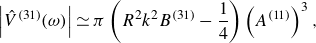 \begin{equation} \left |\hat {V}^{(31)}(\omega )\right | \simeq \pi \left (R^2 k^2 B^{(31)} - \frac {1}{4} \right ) \left (A^{(11)}\right )^3, \end{equation}
where $B^{(31)}(\omega )$
is the Stokes wave coefficient corresponding to
$B^{(31)}(\omega )$
is the Stokes wave coefficient corresponding to $\eta ^{(31)}$
(Zhao & Liu Reference Zhao and Liu2022). The ratio of amplitudes is then
$\eta ^{(31)}$
(Zhao & Liu Reference Zhao and Liu2022). The ratio of amplitudes is then
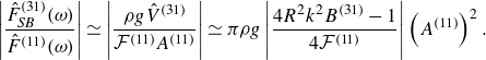 \begin{equation} \left |\frac {\hat {F}_{\textit{SB}}^{(31)}(\omega )}{\hat {F}^{(11)}(\omega )}\right | \simeq \left |\frac {\rho g \hat {V}^{(31)}}{\mathcal {F}^{(11)} A^{(11)}}\right | \simeq \pi \rho g \left |\frac {4R^2 k^2 B^{(31)} - 1}{4\mathcal {F}^{(11)}}\right | \left (A^{(11)}\right )^2. \end{equation}
To draw more accessible relationships from this expression, we consider deep-water conditions and further approximate $\mathcal {F}^{(11)}$
using (5.1), where
$\mathcal {F}^{(11)}$
using (5.1), where $m$
and
$m$
and $b$
are rewritten with expressions from Hulme (Reference Hulme1982) and the kinematics are evaluated at
$b$
are rewritten with expressions from Hulme (Reference Hulme1982) and the kinematics are evaluated at $\bar {z}=0$
for simplicity,
$\bar {z}=0$
for simplicity,
 \begin{equation} \mathcal {F}^{(11)}_{\textit{SB}}(\omega ) = \pi \rho g R^2 \left (1 - \frac {2}{3}KR \left (1+L+\mathcal {O}\left (KR\,\ln (KR)\right )\right )-\mathrm {i}\,\mathcal {O}\left ((KR)^2\right ) \right ), \end{equation}
now in terms of $K$
the deep-water wavenumber and
$K$
the deep-water wavenumber and $L$
the zero-frequency added mass (given by Hulme Reference Hulme1982). As the incident
$L$
the zero-frequency added mass (given by Hulme Reference Hulme1982). As the incident $(31)$
velocity potential is zero (Zhao & Liu Reference Zhao and Liu2022), there is no extra Froude–Krylov
$(31)$
velocity potential is zero (Zhao & Liu Reference Zhao and Liu2022), there is no extra Froude–Krylov $(31)$
term in this case. Thus,
$(31)$
term in this case. Thus,
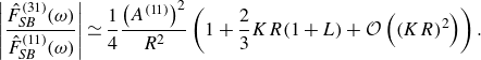 \begin{equation} \left |\frac {\hat {F}^{(31)}_{\textit{SB}}(\omega )}{\hat {F}^{(11)}_{\textit{SB}}(\omega )}\right | \simeq \frac {1}{4}\frac {\left (A^{(11)}\right )^2}{R^2} \left (1 + \frac {2}{3}KR(1+L)+\mathcal {O}\left ((KR)^2\right ) \right ). \end{equation}
The leading term is inherent in (5.4), but the results suggest that the correction becomes more significant as the wavenumber increases from 0, for a small body. The correction from the $\eta ^{(31)}$
term is not important in deep water; however, it could be non-negligible in shallower water.
$\eta ^{(31)}$
term is not important in deep water; however, it could be non-negligible in shallower water.
Finally, we consider some of the implications for general axisymmetric geometries similarly dominated by buoyancy. The dynamic volume of an axisymmetric body with a general vertical profile $r(z)$
in long waves is
$r(z)$
in long waves is
 \begin{equation} V(t) - V_0 \simeq \pi \int _{0}^{\eta (t)} r^2(z)\,\mathrm {d}z. \end{equation}
Any profile $r(z)$
can be written as the sum of even and odd functions and expressed as a Taylor series around
$r(z)$
can be written as the sum of even and odd functions and expressed as a Taylor series around $z = 0$
(which is exact for a sphere). The integrand is therefore
$z = 0$
(which is exact for a sphere). The integrand is therefore
 \begin{equation} r^2(z) = \left (r_{odd}(z) + r_{even}(z)\right )^2 = r^2_{odd}(z) + r^2_{even}(z) + 2r_{odd}(z) r_{even}(z). \end{equation}
Only if the profile is neither odd nor even will there be an odd term in the integrand, $r_{odd}(z) r_{even}(z) \neq 0$
. However, for a purely even or purely odd profile, the volume is only a function of odd powers of
$r_{odd}(z) r_{even}(z) \neq 0$
. However, for a purely even or purely odd profile, the volume is only a function of odd powers of $\eta$
:
$\eta$
:
 \begin{equation} V(t) - V_0 \simeq C_1 \eta (t) + C_3 \eta ^3(t) + C_5 \eta ^5(t) + \cdots \,, \end{equation}
where $C_i$
is a constant coefficient. If the wave is mostly linear,
$C_i$
is a constant coefficient. If the wave is mostly linear, $\eta \rightarrow \eta ^{(11)}$
, then the volume and force harmonics will be mostly composed of odd harmonics. This simple property is noteworthy as it applies to many point absorbers which are typically symmetrical around the waterline, i.e. even vertical profiles. However, in cases where nonlinear waves are non-negligible, e.g. consider
$\eta \rightarrow \eta ^{(11)}$
, then the volume and force harmonics will be mostly composed of odd harmonics. This simple property is noteworthy as it applies to many point absorbers which are typically symmetrical around the waterline, i.e. even vertical profiles. However, in cases where nonlinear waves are non-negligible, e.g. consider $\eta \rightarrow \eta ^{(11)} + \eta ^{(20)} + \eta ^{(22)}$
, then
$\eta \rightarrow \eta ^{(11)} + \eta ^{(20)} + \eta ^{(22)}$
, then $F^{(20)}$
can arise through
$F^{(20)}$
can arise through $\pi R^2 \eta ^{(20)}$
in (5.4), as seen for the hemisphere in figure 6(a) as a setdown, slowly varying downwards force.
$\pi R^2 \eta ^{(20)}$
in (5.4), as seen for the hemisphere in figure 6(a) as a setdown, slowly varying downwards force.
When there are both odd and even powers of $\eta$
in the volume, terms such as
$\eta$
in the volume, terms such as $F^{(20)}$
will contain contributions from both
$F^{(20)}$
will contain contributions from both $\bigl (\eta ^{(11)}\bigr )^2$
and
$\bigl (\eta ^{(11)}\bigr )^2$
and $\eta ^{(20)}$
. For example, the non-hemispherical drafts
$\eta ^{(20)}$
. For example, the non-hemispherical drafts $d/R = 0.6$
and
$d/R = 0.6$
and $0.8$
considered in this study are neither odd nor even profiles around the waterline and thus opposing contributions from
$0.8$
considered in this study are neither odd nor even profiles around the waterline and thus opposing contributions from $\bigl (\eta ^{(11)}\bigr )^2$
and
$\bigl (\eta ^{(11)}\bigr )^2$
and $\eta ^{(20)}$
cause the phase of
$\eta ^{(20)}$
cause the phase of $F^{(20)}$
to ‘flip’ between these drafts, seen in figures 6(c) and 6(e). We note in passing that in this general case there are also additional terms (e.g.
$F^{(20)}$
to ‘flip’ between these drafts, seen in figures 6(c) and 6(e). We note in passing that in this general case there are also additional terms (e.g. $\eta ^{(20)}\eta ^{(11)}$
) that contribute to
$\eta ^{(20)}\eta ^{(11)}$
) that contribute to $F^{(31)}$
.
$F^{(31)}$
.
6. Conclusions and final remarks
The measured heave exciting force on a spherical body in long waves is shown to contain substantial nonlinearity within the wave frequency range. These nonlinear forces are in antiphase with the linear force and manifest as progressive reductions in the wave-to-force TFs. Exploiting the amplitude scaling properties of nonlinear terms, the experimental TFs are fitted to confirm these features are caused by third-order effects. Viscous drag is also briefly considered since it would appear in a similar frequency range; however, its effect on the amplitude and phase of the total first-harmonic force does not align with experimental observations. These findings are further reinforced by numerical results produced from a simplified SB model incorporating instantaneous buoyancy. The model is effective in predicting terms up to third order, due to the dominant contributions of the buoyancy force, but is inapplicable for shorter waves where the SB assumptions are violated. The SB model is also used to derive an expression to estimate the magnitude of these third-order forces on a hemisphere and infer properties of odd and even forces on general axisymmetric geometries dominated by buoyancy.
This study of a simple third-order first-harmonic term may be useful for more general efforts in this area. The methods derived for analysing and extracting the third-order first-harmonic terms, which are typically challenging to isolate, may also be useful for other cases where the primary driver of these nonlinear forces is not buoyancy, but another mechanism. Furthermore, there are other terms formed through difference-frequency interactions in the Stokes expansion, such as the fourth-order second-harmonic term, which cannot be isolated by phase-based methods. These terms can be similarly treated. These results are also important in the context of optimising wave energy converters since they extract power from the wave frequency range and typically undergo large motions which result in substantial nonlinear forces. Improving our understanding of and ability to analyse these nonlinear terms is fundamental for the development of efficient hydrodynamic models in applications such as real-time control systems or fast design iteration processes. This analysis is also currently being extended to comprehensively isolate and extract nonlinear terms from more complex interactions incorporating body motions.
Supplementary materials
Supplementary materials are available at https://doi.org/10.1017/jfm.2025.265.
Funding
This work is funded by the ARC (LP210100397), a UWA Research Impact Grant, and the Blue Economy Cooperative Research Centre CRC-20180101. B.T. is supported by the Aus. Gov. RTP at UWA. H.W. is supported by Shell Aus. A.K. is supported by MERA, jointly funded by UWA and the Western Aus. Gov.
Declaration of interests
The authors report no conflict of interest.
Data availability statement
The authors confirm that the data supporting the findings of this study are available within the supplementary material. This is publicly accessible at https://doi.org/10.1017/jfm.2025.265.


 Open access