


1. Introduction
Steady inertial flow past an angular blunt body has been an important subject in omnipresent physical and engineering applications such as particulate air pollution, river sedimentation and ocean dynamics (Williams & Follows Reference Williams and Follows2011; Gai & Wachs Reference Gai and Wachs2023b). Recent studies investigated the flow past an angular particle, such as a cube or a tetrahedron, at low and moderate Reynolds numbers  ${\mathcal {R}e}\approx {O}(100)$ and revealed the distinctive effects of particle angularity on the flow patterns and regimes (Saha Reference Saha2004; Rahmani & Wachs Reference Rahmani and Wachs2014; Khan, Sharma & Agrawal Reference Khan, Sharma and Agrawal2019; Seyed-Ahmadi & Wachs Reference Seyed-Ahmadi and Wachs2019; Gai & Wachs Reference Gai and Wachs2023a). Vorticity is the essence of bluff body wakes and solid boundaries are the main source of vorticity generation in incompressible flows (Leweke, Le Dizès & Williamson Reference Leweke, Le Dizès and Williamson2016). In aerodynamics, the leading-edge vortex is an essential flow features of agile flight in nature and small-scale vehicles, which is known to affect the lift force in unsteady flows (Eldredge & Jones Reference Eldredge and Jones2019). Another vorticity structure generated on the angular particle surface is the tip vortex, which is closely associated with induced drag, an unavoidable consequence of three-dimensional lift generation (Ringuette, Milano & Gharib Reference Ringuette, Milano and Gharib2007). Mittal & Balachandar (Reference Mittal and Balachandar1995) investigated the generation of the streamwise vortical structure in the near wake of a circular cylinder. It was observed that the streamwise vortices in the unsteady flow are formed due to the stretching of vorticity escaping from the core and the stretching of small-scale streamwise vorticity already present outside the core. In the steady regime, the flow past a sphere generates one pair of opposite-signed vortices in the wake region (Johnson & Patel Reference Johnson and Patel1999). In the case of a cube with a square face facing the flow, four pairs of vortices are generated on the lateral faces of the cube, which form secondary recirculation bubbles (Meng et al. Reference Meng, An, Cheng and Kimiaei2021). The spatial evolution, interaction and merging of these counter-rotating streamwise vortices can affect directly drag and lift forces exerted on the particle (Kriegseis, Kinzel & Rival Reference Kriegseis, Kinzel and Rival2013; Seyed-Ahmadi & Wachs Reference Seyed-Ahmadi and Wachs2019). However, many aspects of the flow interaction with an arbitrary angular particle still remain unclear. Specifically, we seek to answer the following questions: What is the origin of the streamwise vorticity in the particle wake? Can we determine a priori the vorticity pattern based on the shape and angular position of the particle? The Platonic polyhedrons consist of five regular polyhedrons with increasing number of faces, which can model the transition from an angular particle with increasing sphericity to a sphere. By performing 150 simulations of steady flows past a Platonic polyhedron and 75 simulations of freely settling Platonic polyhedrons, our study focuses primarily on the physical insight into the mechanisms responsible for the vorticity generation, as well as on a clear presentation of the key results that are useful for the prediction of dynamics and instabilities of the motion of non-spherical particles.
2. Numerical method and simulation set-up
The distributed Lagrange multiplier/fictitious domain (DLM/FD) method describes a rigid body immersed in a fluid by introducing a fictitious fluid domain, denoted by  $P^*$, which is constrained to possess a rigid body motion. Throughout the rest of this paper, we use an asterisk ( $^*$) to indicate dimensional quantities. The incompressible flow of a Newtonian fluid satisfies the conservation of momentum and mass:
 \begin{gather} \rho_f^*\left(\frac{\partial \boldsymbol{u}^*}{\partial t^*} + (\boldsymbol{u}^*\boldsymbol{\cdot} \nabla^*) \boldsymbol{u}^*\right) ={-}\nabla^* p^* + \mu_f^* \varDelta^*\boldsymbol{u}^* \ \mbox{in} \ \varOmega^*\setminus P^*, \end{gather}
 \begin{gather}\nabla^* \boldsymbol{\cdot} \boldsymbol{u}^*=0 \ \mbox{in} \ \varOmega^*\setminus P^*, \end{gather}
where  $\boldsymbol {u}^*$, $p^*$, $\rho _f^*$ and $\mu _f^*$ represent the velocity, pressure, density and dynamic viscosity of the fluid, respectively, while $\varOmega ^*$ denotes the computational domain.
The DLM/FD method is based on deriving an equation of motion for the fluid–particle mixture by combining the weak formulation of the fluid motion equation with that of the rigid particle (Glowinski et al. Reference Glowinski, Pan, Hesla and Joseph1999). We adopt the numerical approach proposed by Selçuk et al. (Reference Selçuk, Ghigo, Popinet and Wachs2021) that implements the DLM/FD solver in the open-source code Basilisk. This DLM/FD implementation employs an octree adaptive grid, enabling local mesh refinement in specific regions of interest, such as the boundary layer of the particle surface and the particle wake (Gai & Wachs Reference Gai and Wachs2023a). The detailed description of the DLM/FD method has been comprehensively presented in previous works (Wachs et al. Reference Wachs, Hammouti, Vinay and Rahmani2015; Selçuk et al. Reference Selçuk, Ghigo, Popinet and Wachs2021).
First we consider a stationary rigid Platonic polyhedron in an unbounded domain. The computational domain is a large cube of edge length  $L=L^*/D_{sph}^*=40$, where $D^*_{sph}$ is the diameter of the volume equivalent sphere, as depicted in figure 1(a). A Newtonian fluid at a Reynolds number ${\mathcal {R}e} = \rho _f^* U^*D_{sph}^*/\mu _f^*$, where $U^*$ is the far-field fluid velocity, flows past the fixed Platonic polyhedron located at $(x_p, y_p, z_p)=(10, 20, 20)$ at three different angular positions: an edge (E) facing the flow, a face (F) facing the flow and a vertex (V) facing the flow. For more detail about boundary conditions and numerical parameters, please see (Gai & Wachs Reference Gai and Wachs2023a). Then we investigate the freely settling behaviour of a Platonic polyhedron in an unbounded domain, modelled as a large cube of edge length $L=700$, as shown in figure 1(b). The Platonic particle density $\rho _p^*$ to fluid density ratio is set to $m=\rho _p^*/\rho _f^*=2$. The particle is initially placed at the top centre of the cubic domain before being released to settle freely at different Galileo numbers $\mathcal {G}a = \rho _f^* \sqrt {|1-m|g^*D^{*,3}_{sph}}/\mu _f^*$, where $g^*$ is the gravity acceleration. Here $\boldsymbol {u^*}$ satisfies zero Dirichlet conditions on all cubic domain boundaries except on the behind boundary where it satisfies homogeneous Neumann conditions.
Numerical set-up: (a) an inertial flow past a fixed Platonic polyhedron located in a cubic computational domain of side length  $L=40$, streamwise direction is $x^+$, i.e. fluid flows from left to right, far-field velocity is $U=1$; (b) freely settling of a Platonic polyhedron in a computational domain of $L=700$; particle size is not to scale; gravity direction is $y^-$.

3. Results
3.1. Streamwise vorticity pattern
When a steady flow passes a fixed angular particle, a pair of opposite-signed vortices is generated from a front edge, extending into the particle wake region. Figure 2(a) gives a comprehensive listing of the streamwise vorticity  $\omega _x$ patterns in the wake region of a Platonic polyhedron at three angular positions in the $y$–
$y$– $z$ plane. For convenience, we use the two-letter abbreviation for the Platonic polyhedrons: tetrahedron (T), cube (C), octahedron (O), dodecahedron (D) and icosahedron (I); followed by the angular position: edge (E), face (F) and vertex (V). We denote the particle faces on the front surface and not perpendicular to the flow as the first-inclined faces (exceptionally, TF and CF have first-inclined faces on the back and sides due to the absence of front inclined faces). Two observations are deduced from the $\omega _x$ patterns shown in figure 2(a):
(i) Every first-inclined face generates a pair of opposite-signed vortices $\omega _x$ advected to the wake.
(ii) When facing the streamwise direction while standing on an inclined face, the generated vortex pair always has
$\omega _x <0$ (blue) on the left and $\omega _x>0$ (red) on the right.


In face cases, the first front face is perpendicular to the fluid flow and the number of vortex pairs matches the number of first-inclined faces (three for TF, four for CF and five for DF). In edge cases, two inclined faces form a leading edge, resulting in two pairs of opposite-signed vortices. In vertex cases, the number of inclined faces sharing the leading vertex determines the number of vortex pairs (e.g. three for TV and five for IV). Following rule (ii), in the TV case shown in figure 2(a), the front face  $\mathcal {F}_1$ generates a vortex pair ( $\omega _1 < 0$ in blue and $\omega _2 > 0$ in red). As the number of faces on the particle front surface increases, the merging of same-signed $\omega _x$ occurs. In the IF case shown in figure 2(b), two vortices $\omega _1$ and $\omega _2$ are initially generated by face $\mathcal {F}_1$. Face $\mathcal {F}_2$ contributes to the generation of the positive vortex $\omega _3$ (red), but its negative vortex merges with $\omega _1$ (blue). The $\omega _1$ is pushed away in the lateral direction by $\omega _3$, resulting in a weaker value of $\omega _1$ on the plane $x=x_p + 1.5$. Consequently, the $\omega _x$ pattern reveals the relative positions of the particle inclined faces: vortex pairs from upstream faces tend to appear at the rim of the wake region (e.g. IF, DV in figure 2a). In fact, the inclined faces on the particle back also generate vortex pairs following rule (i) and rule (ii), although they are too weak to be visible in the wake region. The consistent compliance with rule (ii) also leads to the chirality of the $\omega _x$ pattern. Generally, the $\omega _{x,max}$ has larger values for particles with lower sphericity as shown in figure 2(a).
Additionally, we draw the contours of  $\omega _x$ on first-inclined faces as shown in figure 2(c). By carefully choosing the cut plane, we confirm that the opposite-signed vortex pairs are generated on the first-inclined faces and exhibit high values near the edges. This vorticity distribution is similar to the separated flow over a finite aspect-ratio plate, the two tips of a front edge generate two streamwise opposite-signed vortices which will be carried by the side surfaces to the particle wake (Kriegseis et al. Reference Kriegseis, Kinzel and Rival2013). In figure 2(a), the $\omega _x$ patterns exhibit highly similar structures between particles at dual angular positions such as (TF, TV), (CF, OV), (CV, OF), (DF, IV) and (DV, IF). The same number of vortex pairs and a similar spatial distribution is observed for dual particles, suggesting that the $\omega _x$ generation is more sensitive to the inclined faces than to the perpendicular face. Indeed, connecting the centre of the faces sharing a common vertex, the number of edges created in the dual particle are exactly the same as the number of faces in the original particle, leading to the same number of inclined faces for particles at dual angular position. The first-inclined faces $\mathcal {S}_{TF,i}$ in the TF case play the same role as the faces $\mathcal {S}_{TV,i}$ in the TV case for $i\in [\![ 1,3 ]\!]$ shown in matching colours in figure 2(d). Similarly, the five faces $\mathcal {S}_{DF,i}$ for $i\in [\![ 1,5 ]\!]$ in the DF case have the same effects as the faces $\mathcal {S}_{IV,i}$ in the IV case, leading to five vorticity pairs in figure 2(a). In the DV case, the $\omega _1$ generated on the secondary face $\mathcal {F}_{1}$ is pushed away and exhibits a weaker value than the $\omega _3$ generated on face $\mathcal {F}_{2}$, following exactly the same mechanism as in the IF case discussed above since IF is the dual of DV. Table 1 summarizes the range of ${\mathcal {R}e}$ in which a multi-planar symmetry of $\omega _x$ (as shown in figure 2a) is observed in the particle wake.
(a) Streamwise vorticity pattern ( $\omega _x > 0$ in red and $\omega _x < 0$ in blue, maximal value $\omega _{x,max}$ in yellow) at $x=x_p+1.5$ in the flow at ${\mathcal {R}e}=100$ downstream a Platonic polyhedron at three angular positions with particle front surface; (b) $\omega _x$ generation and merging in the IF case; (c) $\omega _x$ on the first-inclined surfaces at $x=x_p -0.2$, edges in white; (d) dual angular positions and corresponding faces in matching colours.

The  ${\mathcal {R}e}$ for the multi-planar symmetry regime of flow past a fixed Platonic polyhedron, where A.P. stands for angular position.

3.2. Generation of streamwise vorticity
Having established the deterministic nature and strong dependence of the  $\omega _x$ pattern on the particle front surface geometry, we now seek to elucidate its generation mechanism. In the incompressible Newtonian flow, the vorticity transport equation in Cartesian tensor notation is given by
 \begin{equation} \frac{\partial \omega_i}{\partial t} + u_j \frac{\partial \omega_i}{\partial x_j} = \omega_j\frac{\partial u_i}{\partial x_j} + \frac{1}{{\mathcal{R}e}} \frac{\partial^2 \omega_i}{\partial x_j\partial x_j}. \end{equation}
The first term on the right-hand side describes the stretching and tilting of the vorticity due to the flow velocity gradient, while the second term denotes the viscous diffusion. The total  $\omega _x$ thus arises from the stretching of $\omega _x$ itself and the tilting of the non-streamwise components $\omega _y$ and $\omega _z$, through the terms
 \begin{equation} \omega_x\frac{\partial u_x}{\partial x} + \omega_y\frac{\partial u_x}{\partial y} + \omega_z\frac{\partial u_x}{\partial z}. \end{equation}
Note that the generation of streamwise  $\omega _x$ through tilting and stretching also depends on the gradient of $u_x$. Despite being well described by the partial differential equation (3.1), the behaviour of the vorticity field near boundaries remains controversial (Terrington, Hourigan & Thompson Reference Terrington, Hourigan and Thompson2021). In this paper, we adopt the Lyman boundary vorticity flux (written here in a dimensionless form) to describe the generation of vorticity on a no-slip boundary with unit normal vector $\boldsymbol {n}$ (Lyman Reference Lyman1990; Terrington, Hourigan & Thompson Reference Terrington, Hourigan and Thompson2022):
 \begin{equation} \sigma = \frac{1}{{\mathcal{R}e}} \boldsymbol{n}\times(\boldsymbol{\nabla}\times\boldsymbol{\omega}) ={-}\frac{1}{{\mathcal{R}e}}\boldsymbol{n}\times\boldsymbol{\nabla} p. \end{equation}
When integrated across a closed surface  $S$, (3.3) describes the correct kinematic evolution of the vorticity field, including the viscous diffusion term (Lyman Reference Lyman1990):
 \begin{equation} \int_V \frac{1}{{\mathcal{R}e}}{\rm \Delta}\boldsymbol{\omega} \, {\rm d}V = \int_S \frac{1}{{\mathcal{R}e}}\boldsymbol{n}\times(\boldsymbol{\nabla}\times\boldsymbol{\omega})\, {\rm d} S. \end{equation}
 Figure 3(a) provides an illustration of the vorticity generation mechanism on the angular particle surface. In the CF case, the transverse vorticity components  $\omega _y$ and $\omega _z$ are predominantly generated on the front face, while the streamwise component $\omega _x$ results from the tilting of the transverse components induced by the flow velocity gradient. On the front face of the cube, transverse vorticity components $\omega _{1,z}<0$ and $\omega _{2,z}>0$ are generated on the left and right halves of the front face ( $y>0$ and $y<0$), respectively. Similarly, the transverse vorticity $\omega _{3,y}>0$ is located at the top of the front face, while $\omega _{4,y}<0$ is located at the bottom half. We consider two straight lines $z_c$ and $x_c$ located in the boundary layer of the front and top faces as shown in figure 3(b). Figure 3(c) presents the vorticity components $\omega _x$, $\omega _y$, $\omega _z$ as well as two components of the pressure gradient $\boldsymbol {\nabla } p_y$ and $\boldsymbol {\nabla } p_z$ over the line $z_c$. Along $z_c$, we observe that the pressure gradient $\boldsymbol {\nabla } p_z$ is negative over the cube front surface ( $-0.4\leq y\leq 0.4$). Accordingly, $\omega _y$ ( $\omega _{3,y}$ in figure 3a), is always positive. In contrast, $\boldsymbol {\nabla } p_y$ exhibits two peaks on the two edges: $\boldsymbol {\nabla } p_y = 13$ at $y = -0.4$ and $\boldsymbol {\nabla } p_y = -13$ at $y = 0.4$. Accordingly, we find two peaks on the curve of $\omega _z$ at the same positions. Applying the right-hand rule, the appearance of the $\omega _z$ peaks comes from the pressure gradient $\boldsymbol {\nabla } p_y$ distribution according to (3.3). Since the normal vector of the front face is parallel to the $x$-axis, no contribution to $\omega _x$ comes from (3.3).
(a) Vorticity generation and tilting on a CF surface; (b)  $\omega _x$ and visualization on two lines $x_c$ and $z_c$ over two cube faces; (c–e) vorticity, pressure gradient and velocity gradient evolution along $z_c$ (front face) and $x_c$ (top face).

Figure 3(d) shows the distributions of  $\omega _x$, $\omega _z$ and $\partial u_x/\partial z$ on the straight line $x_c$ in the boundary layer of the top face. Here $\partial u_x/\partial z$ is positive and has two peaks on the cube top face. Meanwhile, $\omega _z$ has a positive peak at $y=-0.4$ and a negative peak at $y=0.4$. Correspondingly, according to the last term of (3.2), the tilting of $\omega _z$ contributes to the positive peak of $\omega _x$ at $y=-0.4$ and to the negative peak at $y=0.4$. The contribution of the second term in (3.2) can be neglected, as the velocity gradient $\partial u_x/\partial y$ is close to zero on the top face between $-0.4 \leq y \leq 0.4$. From figure 3(e), according to (3.3), $\boldsymbol {\nabla } p_y$ generates vorticity with a sign opposite to the observed $\omega _x$. Therefore, the generation of $\omega _x$ is mainly due to the tilting of the transverse vorticity $\omega _z$ and $\omega _y$ generated on the front surface.
In figure 3(a), we denote by  $\omega '_{i,x}$ and $\omega ''_{i,x}$ the streamwise vorticity generated on the secondary face by the tilting of the transverse vorticity $\omega _{i,z}$ with $i\in [\![ 1,3 ]\!]$. In figure 3(c), we see a small peak of $\omega _x$ at $y=-0.4$, corresponding to $\omega '_{3,x}$ in figure 3(a). The tilting of the transverse vorticity following (3.2) leads to rule (ii), where we see $\omega _x<0$ on the left and $\omega _x>0$ on the top face. This vorticity generation mechanism applies to all Platonic polyhedrons examined in this paper and potentially extends to any arbitrary convex angular particles.
3.3. Analogy to far-field polygonal aperture diffraction
The vortex pairs generated on the first-inclined faces are carried downstream, behaving like an image of the particle front surface. Interestingly, they bear a striking resemblance to the far-field diffraction patterns of parallel light beams passing through polygonal apertures. In figure 4(a), we compare the  $\omega _x$ pattern of the flow at ${\mathcal {R}e}=100$ past a TF, CF, DF and a face truncated octahedron to the far-field diffraction pattern of apertures of triangular, square, pentagonal and hexagonal shape, respectively (VirtualLab Fusion 2020). The similarity between these two types of pattern can be observed in their symmetry and complexity. The number of $\omega _x$ pairs is equivalent to that of symmetry axes in the diffraction pattern, such as three for the TF and the triangle aperture, and five for the DF and the pentagon aperture. In figure 4(b), when the edge number is even, the diffraction spikes overlap ( $\mathcal {S}_1$ and $\mathcal {S}_3$, $\mathcal {S}_2$ and $\mathcal {S}_4$) hence the two fringes in the square aperture pattern, while four $\omega _x$ pairs ( $P_1\sim P_4$) are observed in the CF wake. Please note that $\omega _{1,r}$ and $\omega _{2,b}$ are generated from two distinct inclined faces, belonging to two separate vortex pairs. Correspondingly, there are no diagonal spikes present in the diffraction pattern shown in figure 4(b).
(a) Analogy between  $\omega _x$ pattern and the far-field laser diffraction pattern past polygonal apertures: triangle, square, pentagon and hexagon; (b) generation of vortex pairs and overlapping diffraction spikes in the CF case; (c) sketch of $\omega _x$ generation and wake flow streamlines; (d) rotating icosahedron, $\omega _x=\pm 0.3$ contour and wake $\omega _x$ pattern ( $\omega _x >0$ in red and $\omega _x <0$ in blue) at $x= x_p + 1.5$ in the flow at ${\mathcal {R}e}=100$.

Considering a parallel light beam passing through a narrow slit sketched in figure 4(c), the waves from the slit edges interfere constructively on the centre of the screen, leading to a bright fringe. Unlike light waves, the vortices created on the same edge have opposite signs and therefore exhibit opposite phases. Carried downstream by the bulk flow, they form a low vorticity region (white narrow region between red and blue), instead of an enhancement region as observed in light diffraction. Although the vorticity pattern cannot be observed as distinct strips as in the interference of light waves, the fluid provides a unique and powerful way to convey downstream the information about the front surface of an opaque rigid particle. The streamline visualization past the tetrahedron reveals that the flow exhibits tri-axis symmetry in the near-wake region ( $x < x_p + 2$, figure 4(c) ( $\beta$)) as well as in the far-field region ( $x > x_p + 2$, figure 4(c) ( $\delta$)). This tri-axis symmetry acts as a stabilizing factor that helps to preserve the vorticity pattern.
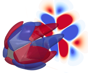
We further investigate the vorticity patterns by rotating an icosahedron around the  $y$-axis by increments of $10^\circ$, capturing the corresponding $\omega _x$ patterns as shown in figure 4(d). Vortices induced by the front face remain on the outer rim of the wake, while the vorticity from the secondary faces stays in the centre. The vorticity pattern changes accordingly to the rotation of the icosahedron. Consequently, the rules (i) and (ii) in § 3.1 allow to determine the vorticity pattern using the information of the particle front surface. The opposite can also be deduced, whereby we can obtain information about the particle front surface, including geometric shape, axis of symmetry and number of edges, from the $\omega _x$ patterns in the wake.
3.4. Stable angular position of a freely settling particle
When an angular particle settles freely in an otherwise quiescent fluid in the steady vertical (SV) regime, it maintains a stable angular position. At higher  $\mathcal {G}a$, the particle exhibits minor tumbling or rotation but still has a preferred angular position in the unsteady vertical (UV), steady/unsteady oblique (O) and the unsteady helical (H) regimes. A comprehensive description of the stable (preferred) angular position for freely settling Platonic polyhedron with increasing $\mathcal {G}a$ is provided in figure 5. We observe the settling particle from the bottom of the computational domain, as depicted in figure 5(f), and project it onto a horizontal plane.
Stable particle angular position of a freely settling particle in the bottom-up view; vorticity patterns for flow past a fixed Platonic polyhedron are illustrated with number of vortex pairs (VP); steady vertical (SV) (blue), unsteady vertical (UV) (yellow), steady oblique (SO) (orange), unsteady oblique (UO) (magenta) and helical (H) (red) regime.

Figure 5(a) shows that the settling tetrahedron maintains only one stable angular position, with its face facing downwards, through three settling regimes (SV, UV and H). The vorticity pattern in the wake region of a moving particle is typically time-dependent and stretched, so we present the vorticity pattern of an ideal case where the flow at the same  ${\mathcal {R}e}$ passes a fixed particle at the stable angular position in figure 5(a). This pattern shows three pairs of vortices created by the TF front surface. Similarly, the settling cube preserves a face facing downwards in the SV and UV regimes in figure 5(b). However, in the helical (H) regime, despite the unsteady path and auto-rotation experienced during settling, a second stable angular position is observed where a cube vertex faces downward. Accordingly, figure 5(b) reveals that the number of vortex pairs decreases from four (CF) to three (CV) from low to high $\mathcal {G}a$. Figures 5(c)–5(e) show the settling behaviour of the octahedron, dodecahedron and icosahedron, respectively. Although the sequence of stable angular positions for each particle is different, it is clear that in all cases the number of vortex pairs decreases as $\mathcal {G}a$ increases.
At low  $\mathcal {G}a$, angular particles tend to have a maximum number of vortex pairs during freely settling. The vorticity pattern comprises equilibrium regions situated between pairs of distinct, stable and opposite-signed vortices. The presence of this equilibrium region reduces the degree of freedom (DOF) of the particle motion. With a maximal number of vortex pairs, the DOF of the particle motion is limited, leading to a steady vertical settling. However, as the relative velocity increases with $\mathcal {G}a$, fluid fluctuations on the particle make it harder to maintain the high number of vortex pairs in the particle wake. Consequently, the particle transitions to a new angular position with fewer but stronger vorticity petals.
4. Conclusions
The present study shows that the generation of the streamwise vorticity in the flow past an angular particle is mainly due to the tilting of the transverse vorticity generated on the particle front surface. The streamwise vorticity pattern in the wake strongly depends on the number of first-inclined faces and can be regarded as an image of the opaque particle front surface. The  $\omega _x$ pattern resembles the far-field diffraction of light passing through a polygonal aperture. The vorticity generation mechanism can be generalized to an arbitrary angular particle, providing a new convenient way to predict a priori the vorticity pairs quantitatively. The vorticity patterns can also be employed to predict the stable angular position of a freely settling angular particle, providing valuable insight into the ability to control fluid flows involving angular rigid bodies. Future work will focus on the effects of inclined face angles, as well as the hydrodynamic forces and torques arising from the vorticity distribution.
Acknowledgements
G.G. expresses his gratitude to the Pacific Institute of Mathematical Sciences for their support via his PIMS-CNRS postdoctoral fellowship. He also thanks Dr D.P. Huet for the insightful conversations.
Funding
The authors greatly appreciate the financial support of the Natural Sciences and Engineering Research Council of Canada (NSERC) via A.W.'s New Frontiers in Research Fund grant NFRFE-2018-01922. This research was enabled by support provided by Compute Canada (http://www.computecanada.ca) through A.W.'s 2022 Computing Resources for Research Groups allocation qpf-764-ac.
Declaration of interests
The authors report no conflict of interest.


 Open access