
 β→∞
β→∞





1. Introduction
The quest for magnetic fusion energy (MFE) has inspired countless magnetic field topologies designed to contain high-temperature plasma. Magnetic confinement devices operate on the principle that a magnetic field constitutes a pressure on charged particles that can insulate them from the vessel walls. However, the particles generate their own pressure, and this complex interaction often results in either macro-instability or catastrophic distortion of the magnetic topology that places strict limits for equilibrium of $\beta \ll 1$
, where
$\beta \ll 1$
, where $\beta$
can be defined locally as the ratio of kinetic plasma pressure to magnetic field pressure. For example, the core
$\beta$
can be defined locally as the ratio of kinetic plasma pressure to magnetic field pressure. For example, the core $\beta$
limit of common tokamak and stellarator topologies is usually less than 0.1 or 10 % (Strait Reference Strait1994).
$\beta$
limit of common tokamak and stellarator topologies is usually less than 0.1 or 10 % (Strait Reference Strait1994).
Topologies that can maintain much higher values of $\beta$
throughout most of the thermonuclear plasma are desirable in MFE for many reasons. In an economic sense, magnetic field energy and the associated current drive represent a large fraction of the cost and complexity of a magnetic confinement device, so they should be minimised for a given plasma energy. The condition
$\beta$
throughout most of the thermonuclear plasma are desirable in MFE for many reasons. In an economic sense, magnetic field energy and the associated current drive represent a large fraction of the cost and complexity of a magnetic confinement device, so they should be minimised for a given plasma energy. The condition $\beta \rightarrow \infty$
also implies that a plasma is highly diamagnetic: it naturally enhances its own external confinement field while depressing the field in its core. This appears an efficient conceptualisation of magnetic confinement: a ‘magnetic wall’.
$\beta \rightarrow \infty$
also implies that a plasma is highly diamagnetic: it naturally enhances its own external confinement field while depressing the field in its core. This appears an efficient conceptualisation of magnetic confinement: a ‘magnetic wall’.
The lack of significant magnetic field pressure within a large volume of laboratory-confined plasma may be advantageous in many contexts inside and outside MFE. For example, fundamental science experiments might be carried out in the highly isotropic core (Forest et al. Reference Forest2015; Patel et al. Reference Patel, Sharma, Ramasubramanian, Ganesh and Chattopadhyay2018). Such plasmas may also find use in large, uniform sources for ion beam extraction (Stirling et al. Reference Stirling, Ryan, Tsai and Leung1979), plasma thrusters (Holste et al. Reference Holste2020; Severn, Baalrud & Foster Reference Severn, Baalrud and Foster2025), materials processing (Machima et al. Reference Machima, Bilek, Monteiro and Brown2000) or antimatter studies (Mohri et al. Reference Mohri, Kanai, Nakai and Yamazaki2005; Ordonez Reference Ordonez2020). The weakly magnetised particle orbits might result in superior stability properties of the configuration (Schmitz et al. Reference Schmitz2016) and good mixing of species for reaction or study. Cyclotron radiation transport from the core might be diminished; although cyclotron-resonant heating possibilities targeting the core may also become restricted.
Superior magneto-hydrodynamic (MHD) stability can be considered another key advantage of certain magnetic topologies that enables them to build up a high-pressure plasma in the first place. Magnetic topologies capable of macro-stability at $\beta \rightarrow \infty$
(without pressure supported by the wall (Fowler et al. Reference Fowler, Hua, Hooper, Moir and Pearlstein1998)) are foremost characterised by lack of helicity: a field-aligned or ‘force-free’ component to the plasma current. Even in ‘minimum energy’ Taylor states (Taylor Reference Taylor1974), this field-aligned current – which can be driven externally or by neoclassical effects – introduces Mercier
$\beta \rightarrow \infty$
(without pressure supported by the wall (Fowler et al. Reference Fowler, Hua, Hooper, Moir and Pearlstein1998)) are foremost characterised by lack of helicity: a field-aligned or ‘force-free’ component to the plasma current. Even in ‘minimum energy’ Taylor states (Taylor Reference Taylor1974), this field-aligned current – which can be driven externally or by neoclassical effects – introduces Mercier $\beta$
limits less than unity (Mercier Reference Mercier1963; Rosenbluth & Bussac Reference Rosenbluth and Bussac1979), provides free energy for micro-instabilities and can beget highly damaging ‘runaway electrons’ during a sudden collapse of plasma pressure known as a disruption.
$\beta$
limits less than unity (Mercier Reference Mercier1963; Rosenbluth & Bussac Reference Rosenbluth and Bussac1979), provides free energy for micro-instabilities and can beget highly damaging ‘runaway electrons’ during a sudden collapse of plasma pressure known as a disruption.
The $\beta \rightarrow \infty$
topologies considered herein generally do not suffer from such issues, and furthermore have the minimum possible magnetic energy that could be deposited to the first wall in the event of a macro-instability. In fact, many topologies do not appear subject to disruptions or macroscopic instabilities at all (Haines Reference Haines1977), which greatly reduces operational risk and simplifies engineering requirements in an experimental program.
$\beta \rightarrow \infty$
topologies considered herein generally do not suffer from such issues, and furthermore have the minimum possible magnetic energy that could be deposited to the first wall in the event of a macro-instability. In fact, many topologies do not appear subject to disruptions or macroscopic instabilities at all (Haines Reference Haines1977), which greatly reduces operational risk and simplifies engineering requirements in an experimental program.
Finally, the possibility of advanced fuel cycles (e.g. D–D, D– $^3$
He and p–
$^3$
He and p– $^{11}$
B) for MFE should be considered an advantage solely of core
$^{11}$
B) for MFE should be considered an advantage solely of core $\beta \gtrsim 50\,\%$
systems. The magnetic field pressure in the plasma implied for a
$\beta \gtrsim 50\,\%$
systems. The magnetic field pressure in the plasma implied for a $\beta \sim 10\,\%$
topology (e.g. traditional tokamak, stellarator) burning these advanced fuels is so large (
$\beta \sim 10\,\%$
topology (e.g. traditional tokamak, stellarator) burning these advanced fuels is so large ( $\gg$
20 T) that such reactors can be considered unfeasible from an engineering standpoint, even with mature high-temperature superconducting technologies. Cyclotron radiation transport might also be more prohibitive for low-
$\gg$
20 T) that such reactors can be considered unfeasible from an engineering standpoint, even with mature high-temperature superconducting technologies. Cyclotron radiation transport might also be more prohibitive for low- $\beta$
systems at the extreme electron temperatures required for advanced fuels.
$\beta$
systems at the extreme electron temperatures required for advanced fuels.
Unfortunately, despite the aforementioned advantages, most topologies capable of core $\beta \gt 1$
are insufficient for MFE due to excessive particle loss along open field lines and/or engineering impossibility. The purpose of this article is to review the many proposed topological options for confinement of plasma at
$\beta \gt 1$
are insufficient for MFE due to excessive particle loss along open field lines and/or engineering impossibility. The purpose of this article is to review the many proposed topological options for confinement of plasma at $\beta \rightarrow \infty$
, where the core of the plasma is sufficiently diamagnetic to exclude the vacuum field and generate a relatively thin ‘scrape-off layer’ (SOL) at the surface. The similar nature of particle losses from topologies with this feature is discussed, leading to conclusions on their viability for scaling to an MFE reactor. Appendix A reviews a relatively unknown and unique topology known as the ‘spherical multipole’ (SM). Appendix B details a generalised model for gas-dynamic particle loss from open systems, and Appendix C comments on the historical use of cusp and mirror topologies for hybrid electromagnetic or ‘magnetic-electrostatic’ confinement efforts.
$\beta \rightarrow \infty$
, where the core of the plasma is sufficiently diamagnetic to exclude the vacuum field and generate a relatively thin ‘scrape-off layer’ (SOL) at the surface. The similar nature of particle losses from topologies with this feature is discussed, leading to conclusions on their viability for scaling to an MFE reactor. Appendix A reviews a relatively unknown and unique topology known as the ‘spherical multipole’ (SM). Appendix B details a generalised model for gas-dynamic particle loss from open systems, and Appendix C comments on the historical use of cusp and mirror topologies for hybrid electromagnetic or ‘magnetic-electrostatic’ confinement efforts.
Some topologies proposed for plasma confinement at $\beta \gtrsim 1$
. Specifically named devices, concepts or companies are starred and referenced in order as Lavrent’ev et al. (Reference Lavrent’ev, Maslov, Nozdracov, Obozny, Golyuk and Krutko2006), Dilkenny, Dangor & Haines (Reference Dilkenny, Dangor and Haines1973), Sadowski (Reference Sadowski1981), Ioffe et al. (Reference Ioffe, Kanaev, Pastukhov, Pitersky and Yushmanov1981), Krall (Reference Krall1992), Forest et al. (Reference Forest2015), McGuire (Reference McGuire2016), Roche et al. (Reference Roche2025) and Scheffel et al. (Reference Scheffel, Jäderberg, Bendtz, Holmberg and Lindvall2025).
$\beta \gtrsim 1$
. Specifically named devices, concepts or companies are starred and referenced in order as Lavrent’ev et al. (Reference Lavrent’ev, Maslov, Nozdracov, Obozny, Golyuk and Krutko2006), Dilkenny, Dangor & Haines (Reference Dilkenny, Dangor and Haines1973), Sadowski (Reference Sadowski1981), Ioffe et al. (Reference Ioffe, Kanaev, Pastukhov, Pitersky and Yushmanov1981), Krall (Reference Krall1992), Forest et al. (Reference Forest2015), McGuire (Reference McGuire2016), Roche et al. (Reference Roche2025) and Scheffel et al. (Reference Scheffel, Jäderberg, Bendtz, Holmberg and Lindvall2025).

2. Topologies proposed for $\beta \rightarrow \infty$
confinement
$\beta \rightarrow \infty$
confinement

One of the fundamental instabilities in magnetised plasmas is the interchange instability (Kruskal, Schwarzschild & Chandrasekhar Reference Kruskal, Schwarzschild and Chandrasekhar1954). Magnetic field pressure must increase in the direction away from the plasma pressure (i.e. towards the wall), otherwise outward plasma displacement represents a release of free energy. Usually, at sufficiently low values of $\beta$
as averaged throughout the plasma, interchange is a global ‘fluting’ mode. In this case, it is possible to make flux tubes stable on average along their full length in the plasma. At higher average
$\beta$
as averaged throughout the plasma, interchange is a global ‘fluting’ mode. In this case, it is possible to make flux tubes stable on average along their full length in the plasma. At higher average $\beta$
, the interchange instability may become localised to regions of unfavourable magnetic pressure gradients and this is known as ‘ballooning’.
$\beta$
, the interchange instability may become localised to regions of unfavourable magnetic pressure gradients and this is known as ‘ballooning’.
As demonstrated by the magnetic topologies empirically capable of $\beta \rightarrow \infty$
confinement, this fundamental instability represents another bane of MFE. It is apparent that a confining equilibrium with plasma pressure exceeding its internal magnetic field pressure can only be achieved in topologies with negligible helicity and the vast majority of the plasma surface stable to interchange/ballooning (the two conditions are related in some ways). Some topologies that have been proposed to satisfy this requirement are shown in figure 1. Note that Z-pinch variants are often not interchange stable, and although they may transiently have core
$\beta \rightarrow \infty$
confinement, this fundamental instability represents another bane of MFE. It is apparent that a confining equilibrium with plasma pressure exceeding its internal magnetic field pressure can only be achieved in topologies with negligible helicity and the vast majority of the plasma surface stable to interchange/ballooning (the two conditions are related in some ways). Some topologies that have been proposed to satisfy this requirement are shown in figure 1. Note that Z-pinch variants are often not interchange stable, and although they may transiently have core $\beta \gtrsim 1$
, are not considered herein due to the inertial nature of their confinement.
$\beta \gtrsim 1$
, are not considered herein due to the inertial nature of their confinement.
The topologies in figure 1 can be organised into three distinct categories. The first is known historically simply as ‘cusp’ topologies, with the most fundamental being the biconic or spindle cusp created by two axisymmetric coils with opposing polarity. ‘Cusp’ topologies are defined herein as intrinsically (i.e. in vacuum with no plasma) containing at least one point or ring of zero magnetic field pressure at the core, such that the plasma’s outer surface can be entirely stable to ballooning (absolute minimum- $B$
). In exchange for total macro-stability, cusps must have open-field topology and include at least one ‘ring’ or ‘line cusp’. Ring/line cusps are to be distinguished from ‘point cusps’ – for example, the biconic cusp topology has two point cusps and one ring cusp. The only peculiar exception to the cusp family is the SM, a family of absolute minimum-
$B$
). In exchange for total macro-stability, cusps must have open-field topology and include at least one ‘ring’ or ‘line cusp’. Ring/line cusps are to be distinguished from ‘point cusps’ – for example, the biconic cusp topology has two point cusps and one ring cusp. The only peculiar exception to the cusp family is the SM, a family of absolute minimum- $B$
topologies that appears to have only point cusps. The SM is detailed further in Appendix A.
$B$
topologies that appears to have only point cusps. The SM is detailed further in Appendix A.
The second category of topologies in figure 1 are referred to in the literature as ‘caulked’, and are mostly ballooning stable. ‘Caulked cusp’ topologies can be thought of as cusp topologies with the ring/line cusp flux tubes linked together by short regions of unfavourable curvature. They can be of open- or closed-field nature. A recent open-field, caulked cusp example is a topology patented by Lockheed Martin Skunk Works and referred to as an ‘encapsulated linear set of ring cusps’ (McGuire Reference McGuire2016). The major limitation with caulked topologies, especially for MFE, is that they require (superconducting) coils to be totally immersed in the plasma, so the coils must be levitated transiently or supported by stalks that intercept some large flux of the ‘recirculating’ plasma. The levitated dipole (Garnier, Kesner & Mauel Reference Garnier, Kesner and Mauel1999) might be considered the most fundamental caulked topology (a ‘caulked solenoid’, if you will), but has a relatively large fraction of the plasma surface area prone to ballooning.
The final category included in figure 1 is the field-reversed and/or high- $\beta$
magnetic mirror. The topology, which is depicted with one but could contain multiple O-points, is somewhat similar to a linear caulked cusp, except that plasma current/diamagnetism is utilised rather than physical, immersed coils. The canonical, axisymmetric mirror system is unstable to interchange, but might still achieve
$\beta$
magnetic mirror. The topology, which is depicted with one but could contain multiple O-points, is somewhat similar to a linear caulked cusp, except that plasma current/diamagnetism is utilised rather than physical, immersed coils. The canonical, axisymmetric mirror system is unstable to interchange, but might still achieve $\beta \rightarrow \infty$
with sufficient input power and stabilisation/suppression efforts (e.g. minimum-
$\beta \rightarrow \infty$
with sufficient input power and stabilisation/suppression efforts (e.g. minimum- $B$
cells and divertors, ‘vortex’ (Beklemishev et al. Reference Beklemishev, Bagryansky, Chaschin and Soldatkina2010) or sheared flow, azimuthal divertors/null rings, ponderomotive forces, etc. (Ryutov et al. Reference Ryutov, Berk, Cohen, Molvik and Simonen2011)). Furthermore, as the plasma pressure approaches the magnetic field pressure in a mirror topology, ion confinement and interchange stability should be enhanced. This theorised positive feedback in a mirror topology, related to the so-called ‘mirror instability’ (Southwood & Kivelson Reference Southwood and Kivelson1993), is due to the significant diamagnetism of the plasma causing an effective increase of the mirror ratio, growth of finite-Larmor-radius effects, and improvement of magnetic pressure gradients in the core.
$B$
cells and divertors, ‘vortex’ (Beklemishev et al. Reference Beklemishev, Bagryansky, Chaschin and Soldatkina2010) or sheared flow, azimuthal divertors/null rings, ponderomotive forces, etc. (Ryutov et al. Reference Ryutov, Berk, Cohen, Molvik and Simonen2011)). Furthermore, as the plasma pressure approaches the magnetic field pressure in a mirror topology, ion confinement and interchange stability should be enhanced. This theorised positive feedback in a mirror topology, related to the so-called ‘mirror instability’ (Southwood & Kivelson Reference Southwood and Kivelson1993), is due to the significant diamagnetism of the plasma causing an effective increase of the mirror ratio, growth of finite-Larmor-radius effects, and improvement of magnetic pressure gradients in the core.
While ballooning-unstable regions must always exist somewhere in an axisymmetric mirror cell, the aforementioned effects may still lead to successful inflation of a ‘diamagnetic bubble’ (Beklemishev Reference Beklemishev2016): a $\beta \gg 1$
, weakly magnetised plasma volume confined within the mirror topology. Any azimuthal current drive by off-axis neutral beam injection (Fisch Reference Fisch1987), preferential momentum loss or other means may contribute to making a diamagnetic bubble look more like a sustained field-reversed configuration (FRC) (Roche et al. Reference Roche2025), with the latter characterised by a significant pressure of reversed magnetic field on-axis. However, unless the current drive is exceptionally strong, the reversed internal field of a ‘sustained FRC’ probably does not provide any additional transport barrier, resulting in similar ion confinement mechanisms to a diamagnetic bubble. The two are not distinguished herein.
$\beta \gg 1$
, weakly magnetised plasma volume confined within the mirror topology. Any azimuthal current drive by off-axis neutral beam injection (Fisch Reference Fisch1987), preferential momentum loss or other means may contribute to making a diamagnetic bubble look more like a sustained field-reversed configuration (FRC) (Roche et al. Reference Roche2025), with the latter characterised by a significant pressure of reversed magnetic field on-axis. However, unless the current drive is exceptionally strong, the reversed internal field of a ‘sustained FRC’ probably does not provide any additional transport barrier, resulting in similar ion confinement mechanisms to a diamagnetic bubble. The two are not distinguished herein.
Cusps and mirrors can also be combined to create confining topologies with ‘X-point’ null rings and private flux regions reminiscent of tokamak divertors. Viewed from the cusp perspective, adding a bias mirror field was referred to in the literature as ‘stuffing’ (Burkhardt, DiMarco & Karr Reference Burkhardt, DiMarco and Karr1969); an example is the toroidal stuffed set of ring cusps or ‘Tormac’ topology (Brown, Kunkel & Levine Reference Brown, Kunkel and Levine1978). Toroidal stuffing requires a rotational transform (poloidal stuffing as well) to prevent drift polarisation. Since stuffed topologies are intended to recover magnetic moment invariance by keeping the plasma core magnetised, they imply $\beta \lesssim 1$
and are therefore out of scope for this work. Inflating the core of a linear stuffed cusp to the
$\beta \lesssim 1$
and are therefore out of scope for this work. Inflating the core of a linear stuffed cusp to the $\beta \rightarrow \infty$
state of interest (if possible) suggests a topology that looks like a field-reversed mirror with azimuthal divertors. Viewed from this high-
$\beta \rightarrow \infty$
state of interest (if possible) suggests a topology that looks like a field-reversed mirror with azimuthal divertors. Viewed from this high- $\beta$
mirror perspective, azimuthal divertors acting as limiters to define the edge of the SOL might contribute to interchange stability (Pastukhov Reference Pastukhov2005). The SM (Appendix A) with its multiple field nulls might be considered a part of this cusp–mirror hybrid family.
$\beta$
mirror perspective, azimuthal divertors acting as limiters to define the edge of the SOL might contribute to interchange stability (Pastukhov Reference Pastukhov2005). The SM (Appendix A) with its multiple field nulls might be considered a part of this cusp–mirror hybrid family.
3. Particle losses from open-field topologies with a thin SOL
With the exception of the caulked toroidal options, confinement of plasma with core $\beta \rightarrow \infty$
requires open-field line topologies relying on magnetic mirroring effects (see figure 1). Since caulking introduces seemingly insurmountable issues related to coil engineering for MFE, only the nature of particle losses from open-field topologies is considered here.
$\beta \rightarrow \infty$
requires open-field line topologies relying on magnetic mirroring effects (see figure 1). Since caulking introduces seemingly insurmountable issues related to coil engineering for MFE, only the nature of particle losses from open-field topologies is considered here.
The ‘ $\beta \rightarrow \infty$
’ plasma state of interest to this work is characterised by an effectively un-magnetised (large ion orbit) core plasma encapsulated by a relatively thin SOL (often called a ‘sheath’ in the cusp literature) that contains most of the diamagnetic current and the transition from kinetic to (equal) magnetic pressure. Of course, with realistic heating methods, many topologies may not exhibit such a state immediately. Low-power cusp experiments are often dominated by a hollow discharge, wherein adiabatic particles far from the null region dominate and can experience anomalous transport towards the null region where they are then lost stochastically. Neutral particle effects may also dominate despite high ionisation fraction in the core (Cooper et al. Reference Cooper, Weisberg, Khalzov, Milhone, Flanagan, Peterson, Wahl and Forest2016). Ostensibly, sufficient confinement and input power is required to burn out neutrals, distend magnetic surfaces and inflate the core to this new state – potentially yielding an enhanced confinement regime characterised by steeper gradients (a kind of ‘H-mode’ for cusps and mirrors). This hysteretic effect on confinement may be what Polywell literature (Bussard & Krall Reference Bussard and Krall1991; Park et al. Reference Park, Krall, Sieck, Offermann, Skillicorn, Sanchez, Davis, Alderson and Lapenta2015) refers to as the ‘wiffleball’.
$\beta \rightarrow \infty$
’ plasma state of interest to this work is characterised by an effectively un-magnetised (large ion orbit) core plasma encapsulated by a relatively thin SOL (often called a ‘sheath’ in the cusp literature) that contains most of the diamagnetic current and the transition from kinetic to (equal) magnetic pressure. Of course, with realistic heating methods, many topologies may not exhibit such a state immediately. Low-power cusp experiments are often dominated by a hollow discharge, wherein adiabatic particles far from the null region dominate and can experience anomalous transport towards the null region where they are then lost stochastically. Neutral particle effects may also dominate despite high ionisation fraction in the core (Cooper et al. Reference Cooper, Weisberg, Khalzov, Milhone, Flanagan, Peterson, Wahl and Forest2016). Ostensibly, sufficient confinement and input power is required to burn out neutrals, distend magnetic surfaces and inflate the core to this new state – potentially yielding an enhanced confinement regime characterised by steeper gradients (a kind of ‘H-mode’ for cusps and mirrors). This hysteretic effect on confinement may be what Polywell literature (Bussard & Krall Reference Bussard and Krall1991; Park et al. Reference Park, Krall, Sieck, Offermann, Skillicorn, Sanchez, Davis, Alderson and Lapenta2015) refers to as the ‘wiffleball’.
In the thin (a few thermal ion gyroradii in the external field or less) SOL considered here, ions in the low- $\beta$
regions that strongly conserve magnetic moment
$\beta$
regions that strongly conserve magnetic moment $\mu$
are of little interest to core confinement. Ions in the core must enter the SOL to be lost along field lines (or, at least, they see an extremely large effective mirror ratio). Therefore, the ion confinement time of the entire plasma might be expressed as
$\mu$
are of little interest to core confinement. Ions in the core must enter the SOL to be lost along field lines (or, at least, they see an extremely large effective mirror ratio). Therefore, the ion confinement time of the entire plasma might be expressed as
 \begin{equation} \tau _{\mathrm{N}} \; \approx \; \tau _\parallel \times \frac {N_{\mathrm{p}}}{N_{\mathrm{SOL}}} \; \approx \; \tau _\parallel \times \frac {R_{\mathrm{p}}}{\eta \times \unicode{x1D6E5}_{\mathrm{SOL}}} , \end{equation}
where $\tau _\parallel$
is the time for loss along open field lines in the SOL,
$\tau _\parallel$
is the time for loss along open field lines in the SOL, ${N_{\mathrm{p}}}/{N_{\mathrm{SOL}}}$
is the ratio of the total number of plasma ions to that of ions in the SOL,
${N_{\mathrm{p}}}/{N_{\mathrm{SOL}}}$
is the ratio of the total number of plasma ions to that of ions in the SOL, $R_{\mathrm{p}} \gg \unicode{x1D6E5}_{\mathrm{SOL}}$
is the plasma major radius and
$R_{\mathrm{p}} \gg \unicode{x1D6E5}_{\mathrm{SOL}}$
is the plasma major radius and $\eta$
is a constant of the order of unity depending on the plasma shape and density profile in the SOL.
$\eta$
is a constant of the order of unity depending on the plasma shape and density profile in the SOL.
The thickness of the SOL at the bulk plasma surface, $\unicode{x1D6E5}_{\mathrm{SOL}}$
, is determined by a balance between the rates of particle diffusion across the magnetic field and loss along the field (Steinhauer, Berk & Team Reference Steinhauer, Berk and Team2018). With subsonic rotation,
$\unicode{x1D6E5}_{\mathrm{SOL}}$
, is determined by a balance between the rates of particle diffusion across the magnetic field and loss along the field (Steinhauer, Berk & Team Reference Steinhauer, Berk and Team2018). With subsonic rotation, $\unicode{x1D6E5}_{\mathrm{SOL}}$
probably cannot be smaller than the ion gyrodiameter
$\unicode{x1D6E5}_{\mathrm{SOL}}$
probably cannot be smaller than the ion gyrodiameter $2 \rho _i$
in the external field
$2 \rho _i$
in the external field $B_{\mathrm{e}}$
 \begin{equation} \unicode{x1D6E5}_{\mathrm{SOL}} \equiv \max { \left ( \sqrt {\chi _\perp \times \tau _\parallel } \; , \; 2 \rho _i \right ) } .\end{equation}
The cross-field diffusivity $\chi _\perp$
and the open-field loss time from the SOL
$\chi _\perp$
and the open-field loss time from the SOL $\tau _\parallel$
might be determined by classical or anomalous processes. Note that, in the
$\tau _\parallel$
might be determined by classical or anomalous processes. Note that, in the $\beta =1$
limit and with
$\beta =1$
limit and with $T_i \approx T_e$
, the ion gyroradius
$T_i \approx T_e$
, the ion gyroradius $\rho _i$
represents the same length scale as the ion skin depth
$\rho _i$
represents the same length scale as the ion skin depth ${c}/{\omega _{pi}}$
 \begin{align} \frac {\rho _i}{{c}/{\omega _{pi}}} = \frac {{m_i v_{i,th}}/{(e B)}}{c \sqrt {{m_i}/({n_i e^2 \varepsilon _0})}} = \frac {v_{i,th}}{v_{\mathrm{A}}} = \sqrt {\beta } \end{align}
where $c$
is the speed of light,
$c$
is the speed of light, $\omega_{pi}$
is the ion plasma frequency,
$\omega_{pi}$
is the ion plasma frequency, $m_i$
is the ion mass,
$m_i$
is the ion mass, $v_{i,th}$
is the ion thermal velocity,
$v_{i,th}$
is the ion thermal velocity, $e$
is the elementary charge,
$e$
is the elementary charge, $B$
is the magnetic field strength,
$B$
is the magnetic field strength, $\epsilon_0$
is the vacuum permittivity,
$\epsilon_0$
is the vacuum permittivity, $v_A$
and is the Alfvén velocity. The only constants of motion for core ions are the total energy
$v_A$
and is the Alfvén velocity. The only constants of motion for core ions are the total energy $H$
(or ‘
$H$
(or ‘ $\varepsilon$
’) and, for axisymmetric topologies, the azimuthal component of the canonical angular momentum
$\varepsilon$
’) and, for axisymmetric topologies, the azimuthal component of the canonical angular momentum $p_\theta$
. Without magnetic moment
$p_\theta$
. Without magnetic moment $\mu$
conservation, either
$\mu$
conservation, either $H$
or
$H$
or $p_\theta$
must provide absolute confinement (i.e. exhibit a ‘loss-cone’-like region in phase space) for ions to stand a chance of exhibiting the ‘adiabatic’ confinement scaling based on the classical ion–ion collision time
$p_\theta$
must provide absolute confinement (i.e. exhibit a ‘loss-cone’-like region in phase space) for ions to stand a chance of exhibiting the ‘adiabatic’ confinement scaling based on the classical ion–ion collision time $\tau _{\parallel \mathrm{ad}} \sim \tau _{ii}$
or better in the collisionless regime. This could be the case with electrostatic confinement by tandem cells (Fowler & Logan Reference Fowler and Logan1977) (via
$\tau _{\parallel \mathrm{ad}} \sim \tau _{ii}$
or better in the collisionless regime. This could be the case with electrostatic confinement by tandem cells (Fowler & Logan Reference Fowler and Logan1977) (via $H$
) or sufficiently negative momentum (via
$H$
) or sufficiently negative momentum (via $p_\theta$
) in certain axisymmetric topologies (e.g. bubble/FRC (Landsman, Cohen & Glasser Reference Landsman, Cohen and Glasser2004; Steinhauer & Nicks Reference Steinhauer and Nicks2025), linear caulked cusp, toroidal set of ring cusps (Dilkenny et al. Reference Dilkenny, Dangor and Haines1973)).
$p_\theta$
) in certain axisymmetric topologies (e.g. bubble/FRC (Landsman, Cohen & Glasser Reference Landsman, Cohen and Glasser2004; Steinhauer & Nicks Reference Steinhauer and Nicks2025), linear caulked cusp, toroidal set of ring cusps (Dilkenny et al. Reference Dilkenny, Dangor and Haines1973)).
Total particle confinement time $\tau _{\mathrm{N}}$
from (3.1) for a field-reversed mirror topology using large D–T reactor parameters:
$\tau _{\mathrm{N}}$
from (3.1) for a field-reversed mirror topology using large D–T reactor parameters: $R_{\mathrm{p}}= 1.5$
m,
$R_{\mathrm{p}}= 1.5$
m, $L=50$
m,
$L=50$
m, $n= 10^{20}$
m
$n= 10^{20}$
m $^{-3}$
,
$^{-3}$
, $\langle m_i \rangle = 4.2 \times10^{-27}$
kg and
$\langle m_i \rangle = 4.2 \times10^{-27}$
kg and $B_{\mathrm{plug}}=20$
T. The adiabatic, gas-dynamic and `enhanced stochastic’ predictions are plotted as a function of ion temperature. An attractive fusion energy gain with D–T fuel in open systems is represented by
$B_{\mathrm{plug}}=20$
T. The adiabatic, gas-dynamic and `enhanced stochastic’ predictions are plotted as a function of ion temperature. An attractive fusion energy gain with D–T fuel in open systems is represented by $n T_i \tau _{\mathrm{N}} \gtrsim 10^{25}\,\mathrm{m^{-3}\,eV\,s}$
.
$n T_i \tau _{\mathrm{N}} \gtrsim 10^{25}\,\mathrm{m^{-3}\,eV\,s}$
.

Preferential loss of the ions with positive momentum contributes to the apparent ‘spin-up’ of axisymmetric mirror plasmas (like FRCs) with lack of sufficient $\mu$
or
$\mu$
or $H$
-based confinement. Maintaining most of the thermalised ion distribution function in negative momentum space (supersonic plasma rotation) could be a basis for ‘centrifugal’ confinement (Lehnert Reference Lehnert1971; Teodorescu et al. Reference Teodorescu, Young, Swan, Ellis, Hassam and Romero-Talamas2010). Rotation of a high-
$H$
-based confinement. Maintaining most of the thermalised ion distribution function in negative momentum space (supersonic plasma rotation) could be a basis for ‘centrifugal’ confinement (Lehnert Reference Lehnert1971; Teodorescu et al. Reference Teodorescu, Young, Swan, Ellis, Hassam and Romero-Talamas2010). Rotation of a high- $\beta$
plasma near or above its sound speed suggests rotational pressure will significantly amplify the external field and may lead to rotational instabilities as seen in many FRC experiments (Steinhauer Reference Steinhauer2011). Supersonic rotation effects on confinement are beyond the scope of this work, in which subsonic rotation is assumed.
$\beta$
plasma near or above its sound speed suggests rotational pressure will significantly amplify the external field and may lead to rotational instabilities as seen in many FRC experiments (Steinhauer Reference Steinhauer2011). Supersonic rotation effects on confinement are beyond the scope of this work, in which subsonic rotation is assumed.
In the simplest picture, $\chi _\perp \sim {\rho _i^2}/{\tau _{ii}}$
and
$\chi _\perp \sim {\rho _i^2}/{\tau _{ii}}$
and $\tau _\parallel \lesssim \tau _{ii}$
such that
$\tau _\parallel \lesssim \tau _{ii}$
such that $\unicode{x1D6E5}_{\mathrm{SOL}} \sim \rho _i$
. In other words, classical scattering events cause ion loss along the field at the same rate as diffusion across it, so the SOL is approximately one ion gyroradius thick. More advanced kinetic theory developed for the diamagnetic bubble suggests a minimum transition layer width
$\unicode{x1D6E5}_{\mathrm{SOL}} \sim \rho _i$
. In other words, classical scattering events cause ion loss along the field at the same rate as diffusion across it, so the SOL is approximately one ion gyroradius thick. More advanced kinetic theory developed for the diamagnetic bubble suggests a minimum transition layer width $\unicode{x1D6E5}_{\mathrm{SOL}} \approx$
6–8
$\unicode{x1D6E5}_{\mathrm{SOL}} \approx$
6–8 $\rho _i$
(Kotelnikov Reference Kotelnikov2020) when
$\rho _i$
(Kotelnikov Reference Kotelnikov2020) when $\rho _i$
is evaluated in the external field
$\rho _i$
is evaluated in the external field $B_e$
.
$B_e$
.
Topologies with ring cusps are an ideal platform to study $\beta \gt 1$
SOL physics, since the thickness of the plasma stream emanating from the ring cusps represents twice the SOL thickness. There is debate in the cusp literature, with many suggesting characteristic SOL thickness much less than the ion gyroradius is possible due to ambipolar (i.e. self-consistent electric field) effects (Haines Reference Haines1977; Park et al. Reference Park, Lapenta, Gonzalez-Herrero and Krall2019). Early sheath theory (e.g. Ferraro Reference Ferraro1952; Rosenbluth Reference Rosenbluth1957; Sestero Reference Sestero1965) can be interpreted (Haines Reference Haines1977) to suggest a scale of the hybrid gyroradius
$\beta \gt 1$
SOL physics, since the thickness of the plasma stream emanating from the ring cusps represents twice the SOL thickness. There is debate in the cusp literature, with many suggesting characteristic SOL thickness much less than the ion gyroradius is possible due to ambipolar (i.e. self-consistent electric field) effects (Haines Reference Haines1977; Park et al. Reference Park, Lapenta, Gonzalez-Herrero and Krall2019). Early sheath theory (e.g. Ferraro Reference Ferraro1952; Rosenbluth Reference Rosenbluth1957; Sestero Reference Sestero1965) can be interpreted (Haines Reference Haines1977) to suggest a scale of the hybrid gyroradius $\unicode{x1D6E5}_{\mathrm{SOL}} \sim \sqrt {\rho _i \rho _e}$
or smaller; actually, quite a few experiments have reported the hybrid gyroradius (Hubble et al. Reference Hubble, Barnat, Weatherford and Foster2014) or even the electron gyroradius (Kitsunezaki, Tanimoto & Sekiguchi Reference Kitsunezaki, Tanimoto and Sekiguchi1974). Could such a thin SOL be achieved at thermonuclear parameters, even the simplest cusp topologies might make attractive reactors. Unfortunately, it appears various micro-instabilities (Yoshino & Sekiguchi Reference Yoshino and Sekiguchi1978; Kozima et al. Reference Kozima, Yamagiwa, Itoh and Sakurai1983; Kozima, Yamagiwa & Kawaguchi Reference Kozima, Yamagiwa and Kawaguchi1984; Pastukhov Reference Pastukhov2021) and neutral gas effects (Bosch & Merlino Reference Bosch and Merlino1986) at a minimum will result in a characteristic
$\unicode{x1D6E5}_{\mathrm{SOL}} \sim \sqrt {\rho _i \rho _e}$
or smaller; actually, quite a few experiments have reported the hybrid gyroradius (Hubble et al. Reference Hubble, Barnat, Weatherford and Foster2014) or even the electron gyroradius (Kitsunezaki, Tanimoto & Sekiguchi Reference Kitsunezaki, Tanimoto and Sekiguchi1974). Could such a thin SOL be achieved at thermonuclear parameters, even the simplest cusp topologies might make attractive reactors. Unfortunately, it appears various micro-instabilities (Yoshino & Sekiguchi Reference Yoshino and Sekiguchi1978; Kozima et al. Reference Kozima, Yamagiwa, Itoh and Sakurai1983; Kozima, Yamagiwa & Kawaguchi Reference Kozima, Yamagiwa and Kawaguchi1984; Pastukhov Reference Pastukhov2021) and neutral gas effects (Bosch & Merlino Reference Bosch and Merlino1986) at a minimum will result in a characteristic $\unicode{x1D6E5}_{\mathrm{SOL}} \gtrsim \rho _i$
. Further investigation on this topic with fusion-relevant plasma pressure is strongly justified.
$\unicode{x1D6E5}_{\mathrm{SOL}} \gtrsim \rho _i$
. Further investigation on this topic with fusion-relevant plasma pressure is strongly justified.
Without absolute confinement by $\mu$
,
$\mu$
, $H$
or
$H$
or $p_\theta$
(or with strong anomalous scattering by mode activity (Tran et al. Reference Tran2025)) the SOL will tend to exhibit losses closer to the gas-dynamic limit:
$p_\theta$
(or with strong anomalous scattering by mode activity (Tran et al. Reference Tran2025)) the SOL will tend to exhibit losses closer to the gas-dynamic limit: $\tau _{\parallel \mathrm{gd}} \equiv ({L \times R_m)}/{v_{i,th}}$
with SOL flux tube length between cusps
$\tau _{\parallel \mathrm{gd}} \equiv ({L \times R_m)}/{v_{i,th}}$
with SOL flux tube length between cusps $L$
, effective mirror ratio
$L$
, effective mirror ratio $R_m \equiv {B_{\mathrm{plug}}}/{B_{\mathrm{e}}}$
and ion thermal velocity (or sound speed)
$R_m \equiv {B_{\mathrm{plug}}}/{B_{\mathrm{e}}}$
and ion thermal velocity (or sound speed) $v_{i,th}$
. The peak field in the cusps from the plug magnets is
$v_{i,th}$
. The peak field in the cusps from the plug magnets is $B_{\mathrm{plug}}$
and
$B_{\mathrm{plug}}$
and $B_e \equiv \sqrt {2 \mu _0 n k_B ( T_i + T_e )}$
is the ‘
$B_e \equiv \sqrt {2 \mu _0 n k_B ( T_i + T_e )}$
is the ‘ $\beta =1$
’ external field assuming negligible pressure from suprathermal particles or plasma rotation. Appendix B shows why
$\beta =1$
’ external field assuming negligible pressure from suprathermal particles or plasma rotation. Appendix B shows why $\tau _{\parallel \mathrm{gd}} \sim {(L \times R_m)}/{v_{i,th}}$
can be used for the gas-dynamic loss time in a mirror configuration (cylinder with two point cusps) and derives similar expressions for some other configurations. As might be expected, the mirror topology has the largest gas-dynamic confinement time for a given SOL volume since it has the fewest loss ‘holes’ (though only by a factor of two compared with the biconic cusp).
$\tau _{\parallel \mathrm{gd}} \sim {(L \times R_m)}/{v_{i,th}}$
can be used for the gas-dynamic loss time in a mirror configuration (cylinder with two point cusps) and derives similar expressions for some other configurations. As might be expected, the mirror topology has the largest gas-dynamic confinement time for a given SOL volume since it has the fewest loss ‘holes’ (though only by a factor of two compared with the biconic cusp).
Figure 2 plots the adiabatic and gas-dynamic particle confinement times from (3.1) for a field-reversed mirror topology using large D–T reactor parameters: $R_{\mathrm{p}}= 1.5$
m,
$R_{\mathrm{p}}= 1.5$
m, $L=50$
m,
$L=50$
m, $n= 10^{20}$
m
$n= 10^{20}$
m $^{-3}$
,
$^{-3}$
, $\langle m_i \rangle = 4.2 \times 10^{-27}$
kg and
$\langle m_i \rangle = 4.2 \times 10^{-27}$
kg and $B_{\mathrm{plug}}=20$
T. It is further assumed that
$B_{\mathrm{plug}}=20$
T. It is further assumed that $\unicode{x1D6E5}_{\mathrm{SOL}} = 2 \rho _i$
,
$\unicode{x1D6E5}_{\mathrm{SOL}} = 2 \rho _i$
, $T_i \approx T_e$
and there are no supersonic rotation effects (
$T_i \approx T_e$
and there are no supersonic rotation effects ( $\langle p_\theta \rangle \sim 0$
). The Coulomb logarithm and hydrogenic ion collision time using the average ion mass
$\langle p_\theta \rangle \sim 0$
). The Coulomb logarithm and hydrogenic ion collision time using the average ion mass $\langle m_i \rangle$
are taken from the NRL formulary (Richardson Reference Richardson2019). Since the actual confinement time cannot be shorter than the gas-dynamic minimum, the adiabatic time can be expressed as a sum of the collisionless adiabatic and gas-dynamic confinement times (Rognlien & Cutler Reference Rognlien and Cutler1980):
$\langle m_i \rangle$
are taken from the NRL formulary (Richardson Reference Richardson2019). Since the actual confinement time cannot be shorter than the gas-dynamic minimum, the adiabatic time can be expressed as a sum of the collisionless adiabatic and gas-dynamic confinement times (Rognlien & Cutler Reference Rognlien and Cutler1980): $\tau _{\parallel \mathrm{ad}} \sim \tau _{ii} + \tau _{\parallel \mathrm{gd}}$
.
$\tau _{\parallel \mathrm{ad}} \sim \tau _{ii} + \tau _{\parallel \mathrm{gd}}$
.
Figure 2 illustrates why gas-dynamic scaling does not yield sufficient confinement time for net fusion energy gain ( $n T_i \tau _{\mathrm{N}} \gtrsim 10^{24}\,\mathrm{m^{-3}\,eV\,s}$
) and further exemplifies how the scaling transition point does not occur (regardless of reactor size) until
$n T_i \tau _{\mathrm{N}} \gtrsim 10^{24}\,\mathrm{m^{-3}\,eV\,s}$
) and further exemplifies how the scaling transition point does not occur (regardless of reactor size) until $T_i \gtrsim 2$
keV. Passing this transition point experimentally represents a significant investment.
$T_i \gtrsim 2$
keV. Passing this transition point experimentally represents a significant investment.
The gas-dynamic scaling applied to (3.1) in the collisionless regime suggests another interpretation of stochastic confinement: that a thermal ion completes on average approximately ${R_{\mathrm{p}}}/{\unicode{x1D6E5}_{\mathrm{SOL}}}$
‘orbits’ or bounces across the topology before loss. This interpretation and scaling likely applies if the ion phase space remains completely isotropic. However, some ‘pseudo-invariants’ might exist (Kotelnikov Reference Kotelnikov2020) that tend to confine certain regions of stochastic phase space much longer than others. The robustness of these pseudo-invariant(s) may be highly dependent on the specific topology and the sharpness of magnetic gradients along field lines.
${R_{\mathrm{p}}}/{\unicode{x1D6E5}_{\mathrm{SOL}}}$
‘orbits’ or bounces across the topology before loss. This interpretation and scaling likely applies if the ion phase space remains completely isotropic. However, some ‘pseudo-invariants’ might exist (Kotelnikov Reference Kotelnikov2020) that tend to confine certain regions of stochastic phase space much longer than others. The robustness of these pseudo-invariant(s) may be highly dependent on the specific topology and the sharpness of magnetic gradients along field lines.
A method to predict the confinement scaling of this pseudo-invariant regime for a given topology might be to find the average number of orbits before loss of a stochastic, collisionless ion (or before degradation of the pseudo-invariant), $\langle N_{\mathrm{orbit}} \rangle$
, which might be independent of temperature if the ratio
$\langle N_{\mathrm{orbit}} \rangle$
, which might be independent of temperature if the ratio ${R_{\mathrm{p}}}/{\rho _i}$
is held constant (i.e. constant size and
${R_{\mathrm{p}}}/{\rho _i}$
is held constant (i.e. constant size and $B_e \propto \sqrt {T_i}$
). The enhancement factor
$B_e \propto \sqrt {T_i}$
). The enhancement factor $\xi$
is also defined as
$\xi$
is also defined as $\langle N_{\mathrm{orbit}} \rangle \equiv ({R_{\mathrm{p}}}/{\unicode{x1D6E5}_{\mathrm{SOL}}}) \: \xi \approx 10 \: \xi$
, such that
$\langle N_{\mathrm{orbit}} \rangle \equiv ({R_{\mathrm{p}}}/{\unicode{x1D6E5}_{\mathrm{SOL}}}) \: \xi \approx 10 \: \xi$
, such that $\xi \gg 1$
would represent a significant improvement over the gas-dynamic confinement prediction. Since the effect only applies in the collisionless regime due to a depletion in phase space, the SOL confinement time of this enhanced stochastic regime might be expressed as
$\xi \gg 1$
would represent a significant improvement over the gas-dynamic confinement prediction. Since the effect only applies in the collisionless regime due to a depletion in phase space, the SOL confinement time of this enhanced stochastic regime might be expressed as
 \begin{equation} \tau _{\parallel \mathrm{es}} \sim \frac { \xi \tau _{\parallel \mathrm{gd}} \times ( \tau _{\parallel \mathrm{gd}}+\tau _{ii} )} {\xi \tau _{\parallel \mathrm{gd}} + \tau _{ii}} .\end{equation}
This definition results in all the expected limits, including $\lim _{\xi \to \infty } \tau _{\parallel \mathrm{es}} = \tau _{\parallel \mathrm{gd}} + \tau _{ii}$
and
$\lim _{\xi \to \infty } \tau _{\parallel \mathrm{es}} = \tau _{\parallel \mathrm{gd}} + \tau _{ii}$
and $\lim _{\tau _{ii} \to \infty } \tau _{\parallel \mathrm{es}}= \xi \: \tau _{\parallel \mathrm{gd}}$
. Equation (3.4) is also plotted in figure 2 for a few values of
$\lim _{\tau _{ii} \to \infty } \tau _{\parallel \mathrm{es}}= \xi \: \tau _{\parallel \mathrm{gd}}$
. Equation (3.4) is also plotted in figure 2 for a few values of $\xi$
. It implies that a stochastic lifetime enhancement factor of
$\xi$
. It implies that a stochastic lifetime enhancement factor of $\xi \gtrsim 10^3$ $( \langle N_{\mathrm{orbit}} \rangle \gtrsim 10^4 )$
would be required to compete with the adiabatic lifetime at reactor parameters (
$( \langle N_{\mathrm{orbit}} \rangle \gtrsim 10^4 )$
would be required to compete with the adiabatic lifetime at reactor parameters ( $n T_i \tau _{\mathrm{N}} \sim 10^{25}\,\mathrm{m^{-3}\,eV\,s}$
).
$n T_i \tau _{\mathrm{N}} \sim 10^{25}\,\mathrm{m^{-3}\,eV\,s}$
).
4. Minimum magnet bore
The ‘limiter’ in a magnetic confinement device is the material (or magnetic separatrix) boundary that defines the outward-most flux surface containing a well-confined plasma. By definition, plasma produced outside of this flux surface is quickly lost along field lines to the limiter.
While the actual limiter might be positioned in any location along field lines, the outward-most possible flux surface containing plasma in an open trap is usually restricted by the bore of the plug magnets. This is because another ostensible advantage of open-field confinement is the natural divertors in the field-flaring region beyond the plug magnets, where the exhausted plasma can be spread over an arbitrarily large material interface or even directly converted to electrical power. This advantage is restricted if the magnet plug bore is too small, such that particles and power impact the limiter in a concentrated fashion rather than passing through the plug bore and spreading out into the divertor.
The required magnet bore to avoid this situation is set by the SOL flux $\varPhi _{\mathrm{SOL}}$
, as defined in Appendix B. The SOL flux radius in a point cusp is
$\varPhi _{\mathrm{SOL}}$
, as defined in Appendix B. The SOL flux radius in a point cusp is $r_{\mathrm{cusp}} \equiv \sqrt {{s_{\mathrm{point}}}/{\pi }} \approx \sqrt {{2 R_{\mathrm{p}} \unicode{x1D6E5}_{\mathrm{SOL}}}/{R_m}}$
. Figure 3 plots the point cusp SOL radius as a function of plasma radius, using the same plasma parameters as in figure 2 and a plugging field of 20 T. It is seen that plug magnets of this strength with warm bores of the order of 1 m would be required for a D–T reactor with ion gyrodiameter scaling of the SOL thickness.
$r_{\mathrm{cusp}} \equiv \sqrt {{s_{\mathrm{point}}}/{\pi }} \approx \sqrt {{2 R_{\mathrm{p}} \unicode{x1D6E5}_{\mathrm{SOL}}}/{R_m}}$
. Figure 3 plots the point cusp SOL radius as a function of plasma radius, using the same plasma parameters as in figure 2 and a plugging field of 20 T. It is seen that plug magnets of this strength with warm bores of the order of 1 m would be required for a D–T reactor with ion gyrodiameter scaling of the SOL thickness.
Radial scale length of the plasma SOL in a point cusp plug magnet as a function of plasma radius for $\unicode{x1D6E5}_{\mathrm{SOL}} = 2 \rho _i$
,
$\unicode{x1D6E5}_{\mathrm{SOL}} = 2 \rho _i$
, $n= 10^{20}$
m
$n= 10^{20}$
m $^{-3}$
,
$^{-3}$
, $\langle m_i \rangle = 4.2 \times 10^{-27}$
kg and
$\langle m_i \rangle = 4.2 \times 10^{-27}$
kg and $B_{\mathrm{plug}}=20$
T. The results are plotted for various ion temperatures
$B_{\mathrm{plug}}=20$
T. The results are plotted for various ion temperatures $T_i$
.
$T_i$
.

5. Conclusions
The magnetic topologies capable of plasma confinement with $\beta \rightarrow \infty$
are reviewed. Such topologies may have conceptual advantages for MFE, but most have critical shortcomings for this application. Nevertheless, many alternative applications of these topologies with lower-temperature plasmas can be found.
$\beta \rightarrow \infty$
are reviewed. Such topologies may have conceptual advantages for MFE, but most have critical shortcomings for this application. Nevertheless, many alternative applications of these topologies with lower-temperature plasmas can be found.
Absolute MHD stability requires open field lines with one or more ring/line cusps, except perhaps in the peculiar SM topology (see Appendix A). Closed-field surfaces can be formed by ‘caulking’ the cusps, but this introduces major engineering issues in supporting and cooling the immersed coils, and the caulked regions may be prone to ballooning as local $\beta \rightarrow 1$
.
$\beta \rightarrow 1$
.
Without absolute confinement criteria from constants of motion such as $H$
,
$H$
, $p_\theta$
or
$p_\theta$
or $\mu$
, plasmas with
$\mu$
, plasmas with $\beta \rightarrow \infty$
can be expected to exhibit particle losses from the SOL near the gas-dynamic rate. Therefore, attractive fusion energy gain based on such topologies might only be possible if (i) the SOL can be made much thinner than one thermal ion gyroradius through ambipolar effects, (ii) sufficient stability exists in the stochastic phase space of certain topologies so as to increase the average number of ion orbits before loss by
$\beta \rightarrow \infty$
can be expected to exhibit particle losses from the SOL near the gas-dynamic rate. Therefore, attractive fusion energy gain based on such topologies might only be possible if (i) the SOL can be made much thinner than one thermal ion gyroradius through ambipolar effects, (ii) sufficient stability exists in the stochastic phase space of certain topologies so as to increase the average number of ion orbits before loss by $\sim$
1000 times over the isotropic prediction or (iii) electrostatic or centrifugal effects are used to recover adiabatic confinement. If one of these cases is realised, an attractive D–T reactor is implied assuming plug magnets capable of
$\sim$
1000 times over the isotropic prediction or (iii) electrostatic or centrifugal effects are used to recover adiabatic confinement. If one of these cases is realised, an attractive D–T reactor is implied assuming plug magnets capable of $\sim$
20 T over a
$\sim$
20 T over a $\sim$
1 m point cusp bore are available. Furthermore, it could enable a path to advanced fuel cycles that will require significantly higher plasma and external magnetic field pressure.
$\sim$
1 m point cusp bore are available. Furthermore, it could enable a path to advanced fuel cycles that will require significantly higher plasma and external magnetic field pressure.
Cusp topologies have also been proposed as a key element to various electromagnetic or ‘magnetic-electrostatic’ approaches to plasma confinement. These attempt to stopper the leakage of plasma through the cusps with applied electric fields. Appendix C comments further on these concepts.
Acknowledgements
The author is grateful for constructive conversations with Dr P. Yushmanov and review of the manuscript by Dr H. Gota.
Editor Cary Forest thanks the referees for their advice in evaluating this article.
Declaration of interests
The author is currently employed by TAE Technologies, a private company developing the field-reversed mirror for fusion applications.
Appendix A. The spherical multipole
The SM family of magnetic topologies (see figures 1 and 4) was first described in a plasma confinement context in Sadowski (Reference Sadowski1967). A series of publications including Sadowski (Reference Sadowski1968) and Sadowski (Reference Sadowski1981) detailed the basic theory of the SM and experimental efforts using the 32-magnet ‘Kaktus’ device. Except for an honourable mention of the device, again by Sadowski (Reference Sadowski2005), in an invited anniversary paper, no other literature on the SM was found by this author. Reference ValfellsValfells (Reference ValfellsU.S. Patent US-4007392-A, Feb. 1977) and Kaldenberg (Reference Kaldenberg1977) describe a tetrahedral minimum- $B$
configuration similar to the SM topology, but distinguished by having line cusps in addition to point cusps.
$B$
configuration similar to the SM topology, but distinguished by having line cusps in addition to point cusps.
The SM topologies are rooted in the Platonic solids, which have high-order symmetry. It allows pseudo-spherical, minimum- $B$
traps to be formed that appear to have only point cusps, and no line cusps. The hairy ball theorem is satisfied by ‘X-points’ (outer field nulls) and ‘internal cusps’ that are formed between the primary cusps. The lowest-order SM useful for plasma confinement is based on the truncated icosahedron and requires 32 magnets forming the point cusps. Lower-order multipoles exist (8- and 14-point), but are trivial for plasma confinement because they have field lines or lines of zero field pressure that connect core to edge.
$B$
traps to be formed that appear to have only point cusps, and no line cusps. The hairy ball theorem is satisfied by ‘X-points’ (outer field nulls) and ‘internal cusps’ that are formed between the primary cusps. The lowest-order SM useful for plasma confinement is based on the truncated icosahedron and requires 32 magnets forming the point cusps. Lower-order multipoles exist (8- and 14-point), but are trivial for plasma confinement because they have field lines or lines of zero field pressure that connect core to edge.
Figure 4 shows a simulation of the magnetic field for a 32-point SM. Two current loops are simulated with the same radial position at each point cusp: a large-diameter shaping coil and small-diameter plug coil. The resulting magnetic pressure surfaces are illustrated.
Analytic simulation showing the structure of magnetic field from 64 current loops arranged in the 32-point SM. The outer coils shape the field between cusps while the inner coils strongly plug the cusps for a total cusp field of about 25 T. All current loop centres are positioned at 5 m radius. Left: magnetic streamlines traced from random points near the trap centre, with different colour in each direction. This illustrates how all field lines exit the trap through the 32 point cusps. Blue and red spheres, with colour indicating polarity, mark the centre of each pair of current loops. Right: isosurfaces of 13 T (yellow) and 0.1 T (purple). The former could represent the surface of the coils, while the latter could be the approximate shape of a low-pressure plasma. High-pressure plasmas would produce significant diamagnetic current that distends the vacuum field.

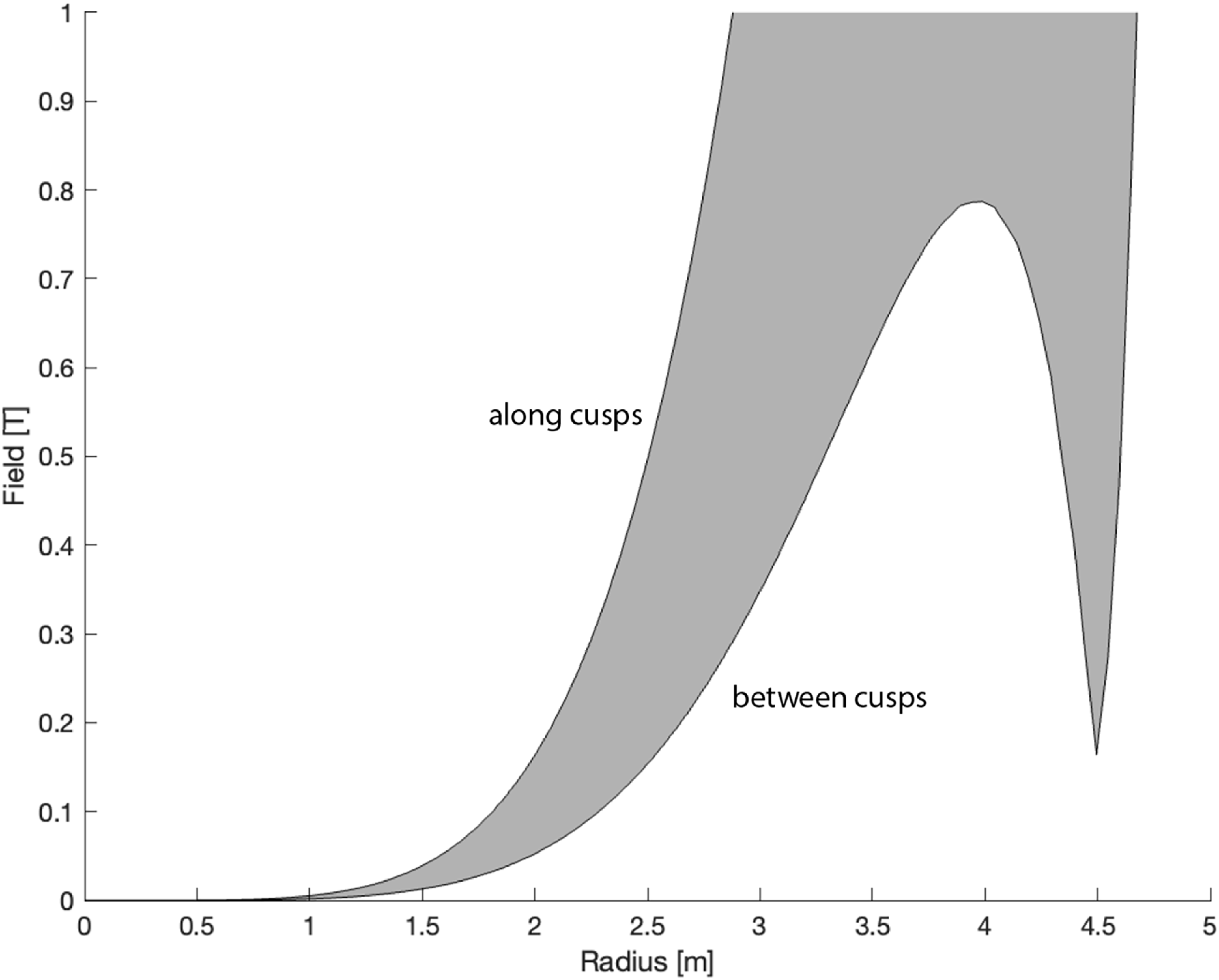
As further evidence that the SM produces a magnetic well, figure 5 displays the vacuum magnetic field strength as a function of radius from the centre of the trap for all possible azimuths and elevations as a shaded region. The upper boundary of this region represents radial paths through the centre of the coils, while the lower boundary represents paths directly between the coils (through the internal cusps and outer field nulls).
Vacuum magnetic field strength as a function of radius from the centre of the 32-point SM of figure 4 for all possible azimuths and elevations. The magnetic well is centred at $r=0$
and coils are at
$r=0$
and coils are at $r=5$
m. An X-point is located at
$r=5$
m. An X-point is located at $r \sim 4.5$
m, outside the internal cusp at
$r \sim 4.5$
m, outside the internal cusp at $r \sim 3.9$
m.
$r \sim 3.9$
m.

The magnetic topology of the SM can also be visualised using figure 6, the top of which depicts half of the SM and field lines traced from only the bore of the top coil. The bottom of figure 6 shows a partial net of the truncated icosahedron, which gives a distorted view of the 32-point SM’s ‘magnetic wall’. The imagined (hand-drawn) trajectory of a particle trapped in this wall under the influence of cross-field drift is sketched in green. In the low- $\beta$
regime, pseudo-adiabatic particles would be expected to bounce back and forth between the cusps while precessing around them, with some passing near the field nulls at the core or X-points (marked with a red ‘S’ in figure 6) that could scramble their magnetic moment to cause stochasticity. Future work might focus on characterising the flux function and low-
$\beta$
regime, pseudo-adiabatic particles would be expected to bounce back and forth between the cusps while precessing around them, with some passing near the field nulls at the core or X-points (marked with a red ‘S’ in figure 6) that could scramble their magnetic moment to cause stochasticity. Future work might focus on characterising the flux function and low- $\beta$
ion orbits in the SM.
$\beta$
ion orbits in the SM.
Left: magnetic field lines traced from the bore of the top coil, showing the high-order symmetry of the field in the 32-point SM. Right: distorted field line structure shown using part of the net of a truncated icosahedron. The imagined characteristic motion of a trapped particle under the influence of strong drift is sketched in green.

Appendix B. Generalised gas-dynamic losses
Gas-dynamic losses can be understood as plasma ions free streaming through the cusps of an open magnetic confinement system in the limit of full collisionality or anomalous scattering in momentum. The effect of a mirror ratio is simply to restrict the plasma flow, much like a nozzle does for neutral gas.
The gas-dynamic confinement time $\tau _{\parallel \mathrm{gd}}$
for the SOL of a
$\tau _{\parallel \mathrm{gd}}$
for the SOL of a $\beta \rightarrow \infty$
configuration can be defined with the rate of its ion inventory loss
$\beta \rightarrow \infty$
configuration can be defined with the rate of its ion inventory loss $\dot {N}_{\mathrm{SOL}}$
as
$\dot {N}_{\mathrm{SOL}}$
as
 \begin{equation} \tau _{\parallel \mathrm{gd}} \; \equiv \; \frac {N_{\mathrm{SOL}} }{\dot {N}_{\mathrm{SOL}} } \; = \; \frac { \tilde {n}_{\mathrm{SOL}} \times A_{\mathrm{p}} \times \unicode{x1D6E5}_{\mathrm{SOL}} } { \tilde {n}_{\mathrm{cusp}} \times S \times v_{i,th} } , \end{equation}
where ${\tilde {n}_{\mathrm{SOL}}}/{\tilde {n}_{\mathrm{cusp}}}$
is the ratio of average density in the SOL at the plasma surface to that in the peak field of the cusp,
${\tilde {n}_{\mathrm{SOL}}}/{\tilde {n}_{\mathrm{cusp}}}$
is the ratio of average density in the SOL at the plasma surface to that in the peak field of the cusp, $A_{\mathrm{p}}$
is the plasma surface area,
$A_{\mathrm{p}}$
is the plasma surface area, $\unicode{x1D6E5}_{\mathrm{SOL}}$
is the SOL thickness,
$\unicode{x1D6E5}_{\mathrm{SOL}}$
is the SOL thickness, $S$
is the total cross-sectional area of SOL flux entering (and exiting) the system through the cusps and
$S$
is the total cross-sectional area of SOL flux entering (and exiting) the system through the cusps and $v_{i,th} = \sqrt {{(2 \times k_B \times T_i)}/{m_i}}$
is the ion thermal velocity (assumed to be similar to the sound speed).
$v_{i,th} = \sqrt {{(2 \times k_B \times T_i)}/{m_i}}$
is the ion thermal velocity (assumed to be similar to the sound speed).
The SOL minimum cross-section in a single point cusp can be expressed as
 \begin{equation} s_{\mathrm{point}}= \frac {\varPhi _{\mathrm{SOL}}}{B_{\mathrm{plug}}} , \end{equation}
where $B_{\mathrm{plug}}$
is the peak applied field in the cusp. The SOL flux can be roughly approximated (within a factor of
$B_{\mathrm{plug}}$
is the peak applied field in the cusp. The SOL flux can be roughly approximated (within a factor of $\sim$
2 for most configurations) as
$\sim$
2 for most configurations) as
 \begin{equation} \varPhi _{\mathrm{SOL}} \sim 2 \: \pi \times R_{\mathrm{p}} \times \unicode{x1D6E5}_{\mathrm{SOL}} \times B_e , \end{equation}
where $R_{\mathrm{p}} \gg \unicode{x1D6E5}_{\mathrm{SOL}}$
is the plasma major radius. The external field
$R_{\mathrm{p}} \gg \unicode{x1D6E5}_{\mathrm{SOL}}$
is the plasma major radius. The external field $B_e \equiv \sqrt {2 \mu _0 n k_B ( T_i + T_e )}$
is assumed to scale with the thermal plasma pressure, although in some cases might be amplified significantly by fast particle pressure (Roche et al. Reference Roche2025).
$B_e \equiv \sqrt {2 \mu _0 n k_B ( T_i + T_e )}$
is assumed to scale with the thermal plasma pressure, although in some cases might be amplified significantly by fast particle pressure (Roche et al. Reference Roche2025).
For a mirror topology with two point cusps, $S_{\mathrm{FRM}}=s_{\mathrm{point}}$
. For the 32-point SM,
$S_{\mathrm{FRM}}=s_{\mathrm{point}}$
. For the 32-point SM, $S_{\mathrm{SM}}=20 \times s_{\mathrm{point}}$
. For the biconic cusp, the flux that enters through the point cusps must exit through the ring cusp. Therefore, the biconic cusp has
$S_{\mathrm{SM}}=20 \times s_{\mathrm{point}}$
. For the biconic cusp, the flux that enters through the point cusps must exit through the ring cusp. Therefore, the biconic cusp has $S_{\mathrm{BC}}=2 \times s_{\mathrm{point}}$
. The cusp-ended mirror has flux from two point cusps plus an additional line cusp, so
$S_{\mathrm{BC}}=2 \times s_{\mathrm{point}}$
. The cusp-ended mirror has flux from two point cusps plus an additional line cusp, so $S_{\mathrm{CEM}}= 3 \times s_{\mathrm{point}}$
. Therefore, the mirror topology can be expected to have the longest gas-dynamic confinement time for a given SOL volume.
$S_{\mathrm{CEM}}= 3 \times s_{\mathrm{point}}$
. Therefore, the mirror topology can be expected to have the longest gas-dynamic confinement time for a given SOL volume.
Finally, the density ratio between the peak cusp field and bulk plasma might be estimated as
 \begin{equation} \frac {\tilde {n}_{\mathrm{cusp}}}{\tilde {n}_{\mathrm{SOL}}} = R_m \times f_{\mathrm{lc}} = R_m \times \left (1 - \sqrt {\frac {R_m-1}{R_m}} \right ) \approx 0.5 , \end{equation}
where the mirror ratio factor $R_m$
is due to compression of the flux tubes entering the cusp and
$R_m$
is due to compression of the flux tubes entering the cusp and $f_{\mathrm{lc}}$
is the fraction of an isotropic particle distribution that is in the magnetic moment (
$f_{\mathrm{lc}}$
is the fraction of an isotropic particle distribution that is in the magnetic moment ( $\mu$
) loss cone. Equation (B4) evaluates to nearly 0.5 for values of
$\mu$
) loss cone. Equation (B4) evaluates to nearly 0.5 for values of $R_m \gg 1$
.
$R_m \gg 1$
.
In the limit $R_{\mathrm{p}} \rightarrow \unicode{x1D6E5}_{\mathrm{SOL}}$
and assuming
$R_{\mathrm{p}} \rightarrow \unicode{x1D6E5}_{\mathrm{SOL}}$
and assuming $A_{\mathrm{p}} \approx 2 \; \pi \times R_{\mathrm{p}} \times L$
for the flux tube length
$A_{\mathrm{p}} \approx 2 \; \pi \times R_{\mathrm{p}} \times L$
for the flux tube length $L$
of cylindrical configurations, (B1) simplifies to the often-cited expression for gas-dynamic confinement time in a low-
$L$
of cylindrical configurations, (B1) simplifies to the often-cited expression for gas-dynamic confinement time in a low- $\beta$
mirror (Ivanov & Prikhodko Reference Ivanov and Prikhodko2013)
$\beta$
mirror (Ivanov & Prikhodko Reference Ivanov and Prikhodko2013)
 \begin{equation} \tau _{\parallel \mathrm{gd}} \approx \frac {L \times R_m}{v_{i,th}} .\end{equation}
Appendix C. Cusp configurations for electromagnetic confinement
Various embodiments of ‘electromagnetic’ or ‘magnetic-electrostatic’ confinement (Dolan Reference Dolan1994) have evolved from the electrostatic plugging of open-ended magnetic systems (Ware & Faulkner Reference Ware and Faulkner1969; Hinrichs, Lichtenberg & Dolan Reference Hinrichs, Lichtenberg and Dolan1977) and the magnetic shielding of electrodes in inertial electrostatic confinement systems (Miley & Murali Reference Miley and Murali2014). In both cases, some sort of high-voltage electrode structure is placed outside of the cusp topology, in what would be the ‘divertors’ of the open-field magnetic trap. Similarly to the practice of end biasing in mirrors (Beklemishev et al. Reference Beklemishev, Bagryansky, Chaschin and Soldatkina2010), rotation control and plasma heating might be expected via crossed-field effects and high-energy particle beam injection.
With electromagnetic confinement concepts, however, it is proposed that additional, self-consistent electrostatic structures can be generated (Krall et al. Reference Krall, Coleman, Maffei, Lovberg, Jacobsen and Bussard1995; Nebel & Barnes Reference Nebel and Barnes1998; Gu & Miley Reference Gu and Miley2000), which enhance the ion confinement or fusion performance beyond the magnetic confinement model presented herein. In other words, both ions and electrons can simultaneously be subject to electrostatic confinement in a single minimum- $B$
cell. Figure 7 shows how such an electrostatic structure is typically envisioned, with magnetic-electrostatic confinement applied to the simple biconic cusp. Similarities to the electrostatic structure of a tandem mirror system might be noted, with the latter produced by the ambipolar effects of multiple confinement cells rather than by electrodes directly.
$B$
cell. Figure 7 shows how such an electrostatic structure is typically envisioned, with magnetic-electrostatic confinement applied to the simple biconic cusp. Similarities to the electrostatic structure of a tandem mirror system might be noted, with the latter produced by the ambipolar effects of multiple confinement cells rather than by electrodes directly.
Axisymmetric topology (top) and on-axis potential (bottom) for `Lavrent’ev-style’ magnetic-electrostatic plasma confinement in a simple biconic cusp. The dashed line is the vacuum potential (voltage) with no plasma present. $\Delta \phi$
is the self-shielding potential due to uncompensated electron space-charge effects,
$\Delta \phi$
is the self-shielding potential due to uncompensated electron space-charge effects, $\phi _i$
is the potential barrier for ions and
$\phi _i$
is the potential barrier for ions and $\phi _e$
is the potential barrier for electrons. The sum of these three potentials is equal to the applied voltage,
$\phi _e$
is the potential barrier for electrons. The sum of these three potentials is equal to the applied voltage, $\phi _a$
. Reprinted with permission from Sporer (Reference Sporer2022).
$\phi _a$
. Reprinted with permission from Sporer (Reference Sporer2022).

The most well-known electromagnetic confinement efforts for fusion energy include those of physicist O. Lavrent’ev at KIPT (Lavrent’ev Reference Lavrent’ev1975; Lavrent’ev et al. Reference Lavrent’ev, Maslov, Krutko and Oboznyj2008), the ATOLL toroidal multipole device at the Kurchatov Institute (Ioffe et al. Reference Ioffe, Kanaev, Pastukhov, Pitersky and Yushmanov1981; Pastukhov Reference Pastukhov2021) and the Polywell concept developed by R. Bussard and the private company EMC2 (Krall Reference Krall1992; Park & KrallReference Park and Krall2018). These concepts use minimum- $B$
topologies and plasmas near thermodynamic equilibrium. Minimum-
$B$
topologies and plasmas near thermodynamic equilibrium. Minimum- $B$
electromagnetic topologies have also been proposed for cold antimatter confinement (Hedlof & Ordonez Reference Hedlof and Ordonez2017). Other mirror-like, ‘centrifugal electromagnetic’ approaches have been proposed as well (e.g. Maglich (Reference Maglich1973) and Affolter et al. (Reference Affolter2024)) – these are essentially ‘beam fusion’ concepts pushing the space-charge limits for useful fusion power density.
$B$
electromagnetic topologies have also been proposed for cold antimatter confinement (Hedlof & Ordonez Reference Hedlof and Ordonez2017). Other mirror-like, ‘centrifugal electromagnetic’ approaches have been proposed as well (e.g. Maglich (Reference Maglich1973) and Affolter et al. (Reference Affolter2024)) – these are essentially ‘beam fusion’ concepts pushing the space-charge limits for useful fusion power density.
The legitimacy of electrostatic confinement methods for MFE can be called into question simply on the basis of the extreme electric field ( $\sim$
MV/cm) required to match MFE-relevant plasma pressure. Furthermore, it might be expected that the plasma must have a Debye length comparable to its dimensions in some regions for external electric fields to have any internal effect on it. Therefore, while complex and intriguing electromagnetic confinement structures resulting in
$\sim$
MV/cm) required to match MFE-relevant plasma pressure. Furthermore, it might be expected that the plasma must have a Debye length comparable to its dimensions in some regions for external electric fields to have any internal effect on it. Therefore, while complex and intriguing electromagnetic confinement structures resulting in $n T_i \tau _{\mathrm{N}} \rightarrow 10^{24}\,\mathrm{m^{-3}\,eV\,s}$
might be produced at low density (
$n T_i \tau _{\mathrm{N}} \rightarrow 10^{24}\,\mathrm{m^{-3}\,eV\,s}$
might be produced at low density ( $n \ll 10^{19}$
m
$n \ll 10^{19}$
m $^{-3}$
) in various concepts, the fusion power density would be impractically low regardless of ion energy distribution (Ordonez & Weathers Reference Ordonez and Weathers2023). Raising the particle and power density to levels useful for energy generation (
$^{-3}$
) in various concepts, the fusion power density would be impractically low regardless of ion energy distribution (Ordonez & Weathers Reference Ordonez and Weathers2023). Raising the particle and power density to levels useful for energy generation ( ${\gg} 1\,{\mathrm{kW}}\,{\mathrm{m}^{-3}}$
) is expected to wash out any clever electrostatic structures except the ambipolar ones that are intrinsic to plasma and magnetic confinement. For example, consider the difficulty in maintaining the ‘thermal barrier’ electrostatic structure in a single cell at high density in tandem mirror systems (Kesner et al. Reference Kesner, Gerver, Lane, Vey, Aamodt, Catto, Dippolito and Myra1983). Furthermore, fusion-relevant density may begin to excite the many micro-instabilities that would be expected of beam-like devices with large ion anisotropy.
${\gg} 1\,{\mathrm{kW}}\,{\mathrm{m}^{-3}}$
) is expected to wash out any clever electrostatic structures except the ambipolar ones that are intrinsic to plasma and magnetic confinement. For example, consider the difficulty in maintaining the ‘thermal barrier’ electrostatic structure in a single cell at high density in tandem mirror systems (Kesner et al. Reference Kesner, Gerver, Lane, Vey, Aamodt, Catto, Dippolito and Myra1983). Furthermore, fusion-relevant density may begin to excite the many micro-instabilities that would be expected of beam-like devices with large ion anisotropy.
‘Lavrent’ev-style’ electromagnetic confinement approaching thermonuclear para- meters might be feasible if the plasma streaming through the ring cusps can be made especially thin and tenuous ( $\unicode{x1D6E5}_{\mathrm{SOL}} \ll \rho _i$
and/or
$\unicode{x1D6E5}_{\mathrm{SOL}} \ll \rho _i$
and/or ${\tilde {n}_{\mathrm{cusp}}}/{\tilde {n}_{\mathrm{SOL}}} \ll 1$
). As such, it is concluded by this author that the efficacy of any electromagnetic confinement methods for fusion energy is closely related to the nature and characteristic thickness of the SOL in high-
${\tilde {n}_{\mathrm{cusp}}}/{\tilde {n}_{\mathrm{SOL}}} \ll 1$
). As such, it is concluded by this author that the efficacy of any electromagnetic confinement methods for fusion energy is closely related to the nature and characteristic thickness of the SOL in high- $\beta$
open systems, which is an important unresolved physics question. It is possible that the achievement of sub-ion scale structure would allow electromagnetic confinement to be extrapolated to some regime of interest for fusion energy (Sporer Reference Sporer2022). Meanwhile, such devices continue to provide interesting alternative applications in plasma science.
$\beta$
open systems, which is an important unresolved physics question. It is possible that the achievement of sub-ion scale structure would allow electromagnetic confinement to be extrapolated to some regime of interest for fusion energy (Sporer Reference Sporer2022). Meanwhile, such devices continue to provide interesting alternative applications in plasma science.


 β≳1
β≳1
 τN
τN Rp=1.5
 L=50
L=50 n=1020
 −3
−3 ⟨mi⟩=4.2×10⁻²⁷
 Bplug=20
 nTiτN≳1025m−3eVs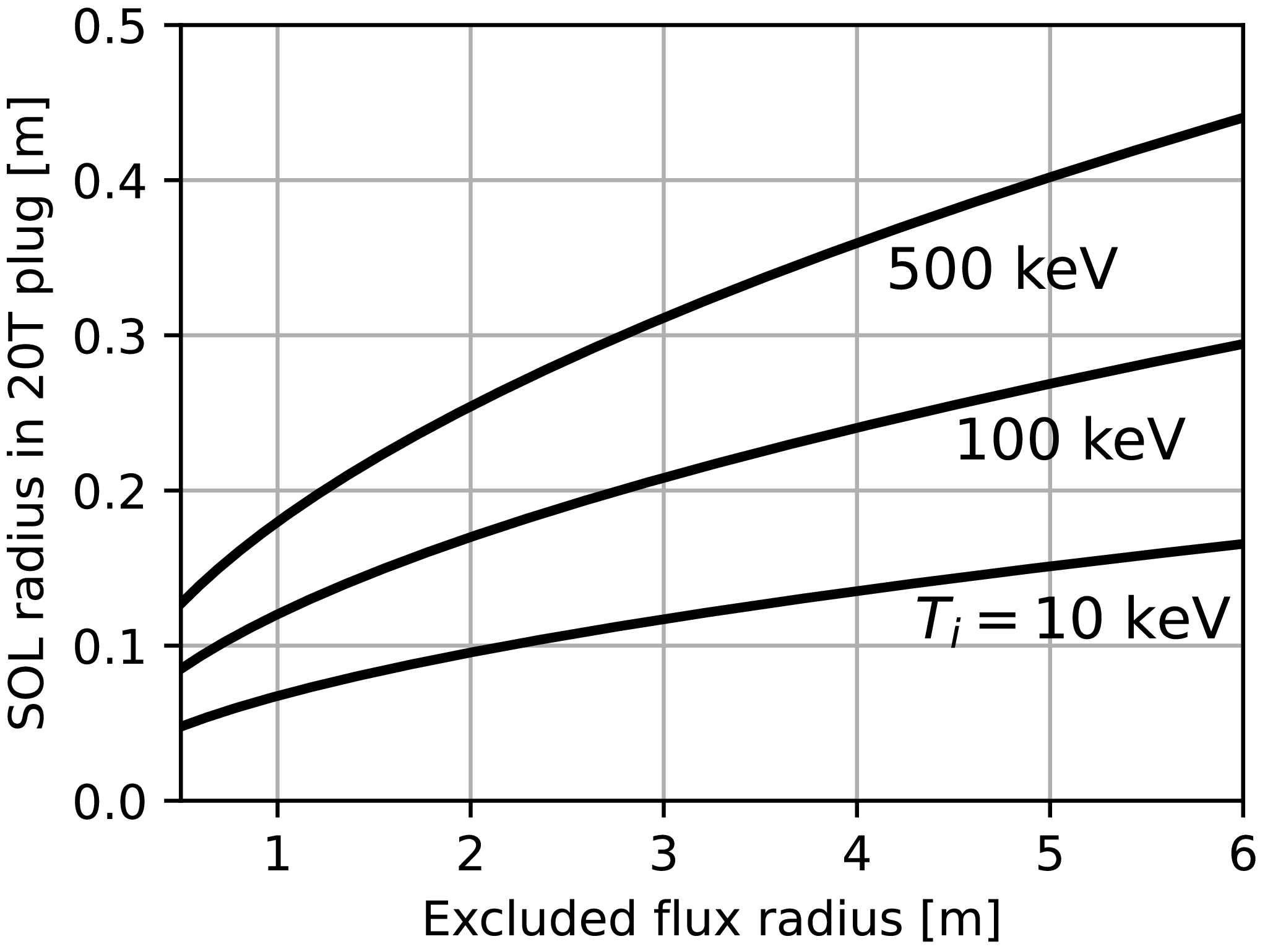
 𝛥SOL=2ρi
 n=1020
 −3
−3 ⟨mi⟩=4.2×10⁻²⁷
 Bplug=20
 Ti
Ti
 r=0
r=0 r=5
r=5 r∼4.5
r∼4.5 r∼3.9
r∼3.9

 Δϕ
Δϕ ϕi
ϕi ϕe
ϕe ϕa
ϕa
 Open access

