





Introduction
An earlier version of this paper was presented at the European Radar Conference (EuRAD) and was published in its Proceedings [Reference Schenkel, Schulz, Baer and Rolfes1]. Plasma is an ionized gas excited by the input of a certain amount of energy. The ignited plasma consists of ions, electrons, and neutral gas particles. The used power source, the applied gas type, and the gas pressures define the final application and its outcome. Plasma processes are among the key technologies for future innovations in research and development, especially in the field of plasma-assisted deposition, cleaning, and etching [Reference Charles2].
The resulting product quality is directly influenced by plasma-dependent process parameters such as plasma electron density, collision frequency, and electron temperature. Consequently, plasma diagnostics are essential for an effective control loop of a process. The great potential of plasma is leading to an increasing focus of research on plasma diagnostics. Due to the wide range of applications, very high demands are placed on suitable plasma diagnostics [3].
Simultaneously, minimally invasive, and contactless diagnostic methods are preferred in industry. It is important that the production processes are not influenced by the diagnostics. For technical and economic reasons, the effort to implement new diagnostics should be low. As a result, measurement concepts are used that monitor external parameters such as generator power, plasma impedance, gas flow, or pressure. Advantageously, these sensors can be usually installed without affecting the process and therefore, do not have to be setup in a complex and expensive procedure. However, it is difficult to make an accurate statement about the plasma state based on these measurements. Nevertheless, the increasing requirements for modern coating processes and applications are leading to an even greater elaborateness of the phenomena that needs to be taken into account [Reference Hopkins and Lawler4].
Thus, the focus of research is shifting to innovative probe concepts that enable direct measurements of internal plasma parameters. A very well established probe concept is the Langmuir probe [Reference Auciello and Flamm5]. It is a widely used diagnostic in research and allows local measurements in the plasma. It enables spatially and time-resolved information. However, the Langmuir probe has a limited validity in dielectric coating processes. If the coating of the probe is not taken into account, large measurement deviations will occur. If the dielectric layer is too thick, the probe will fail completely. In order to be able to measure dielectric coating processes as well, a multipole resonance probe (MRP) was developed [Reference Schulz, Styrnoll, Storch, Awakowicz, Musch and Rolfes6]. Dielectric coatings do not interfere with the MRP measurements. The measurement method itself is relatively straightforward, since the resonance of the electrons is measured and thus, the electron density can be determined. The MRP can also be used to perform spatially resolved measurements. However, the MRP cannot be used in metallic deposition processes, since a too thick metallic layer will lead to a system failure. In general, the two probes are very powerful diagnostic methods. However, in order to offer spatially resolved measurements, they must be placed and moved directly inside the plasma. This is not in the industry's expectations, which means that the probe concepts are not widely used in production. It is becoming apparent that it will be difficult to find a universal diagnostic solution for the wide range of applications. There is a growing demand for less invasive diagnostic methods. Thus, in [Reference Pohle, Schulz, Oberberg, Awakowicz and Rolfes7], the design of the MRP was changed to hide it in the reactor wall and not cause any interference in the plasma. Another established non-invasive diagnostic method is the optical emission spectroscopy [Reference Salimian, Haghpanahan, Hasnath and Upadhyaya8]. Based on precise and complex plasma models chemical species can be detected. Nevertheless, it is challenging to derive the plasma state from the obtained optical spectrum.
Obviously, it is challenging to determine the internal state of the plasma in a contactless and minimally invasive way. In order to be capable of detecting plasma dynamic processes, a fast measurement is required that can resolve the slightest inhomogeneities and fluctuations in the plasma independently of the type of gas composition as well as the excitation method. So, the new approach is to use radar sensors to supervise the plasma. The utilization of radar technology in the field of contactless material characterization has become increasingly important in recent years [Reference Barowski, Zimmermanns and Rolfes9]. In particular, due to the use of millimeter wave radar systems in the automotive sector, knowledge of the material properties at the respective frequency is of great interest. Both the magnitude and the phase of the radar signal are used for evaluation. For precise results, calibration can be advantageous.
Previous work as in [Reference Baer, Jaeschke, Pohl and Musch10] shows monitoring techniques of pressure changes in gas facilities by using radar sensors. This approach takes advantage of the fact that smallest changes in pressure cause a change in relative permittivity. This approach was then extended in [Reference Hattenhorst, Baer and Musch11] by real-time monitoring of turbulent gas flows for flow velocity detection. In [Reference Baer, Gerding, Pohl, Vogt and Musch12], pneumatically conveyed bulk materials were detected based on the measured transit times of a radar signal and the volume density and conveying velocity were investigated.
Based on this previous work, radar-based measurements will be used to monitor the plasma state in this work. Measurements based on high precise phase evaluations of a frequency-modulated continuous wave (FMCW) radar sensor are able to detect small changes of the process state in low-pressure plasmas. In this article, the concept is presented and tested. Measurements are taken at center frequencies of 80 and 140 GHz to highlight the frequency-dependent behavior of the plasma. In order to get an impression of plasma state parameters and the behavior of electromagnetic waves in plasmas, Section “Plasma model” presents the plasma fundamentals. The measurement effect will be very small, so the basics of phase-based distance determination will be discussed in Section “Phase-based distance estimation.” This will enable highly precise measurements to detect even the smallest variations in the plasma state. In Section “Simulation,” the theory is validated with full-wave simulations. Finally, measurement results of capacitively coupled plasma (CCP) in a side-by-side comparison of two frequency ranges are presented in Section “Measurements.”
Plasma model
Henceforth, the plasma is considered from an electromagnetic point of view. It consists of different particle species, which influence the behavior of the plasma with varying intensity. Electrons, ions, radicals, atoms, and molecules are generated in the plasma by collision processes. However, the electrons and ions have the greatest influence on the propagating wave. In a more macroscopic view, the low pressure plasma is electrically neutral or it can be assumed to be quasi-neutral:

Here, n e is the electron density and n i is the ion density, equalized to the charge density n 0. Due to their masses, electrons and ions react differently to an external field. Electrons are significantly faster accelerated by an external electric field than ions. Due to their inertia, they move past the ion and are subsequently attracted again. This oscillating motion can be described by the electron plasma frequency [Reference Bittencourt13]:

with e the elementary charge, $\varepsilon _{0}$ the dielectric constant, and m e the electron mass. The oscillation frequency of the ions can be described by exchanging the mass of the electrons for the mass of the ions. Because of the higher mass of the ions, the ion plasma frequency is significantly lower than from the electrons. The particles can only follow an external field if its frequency is below the plasma frequency of the particles. At frequencies above the plasma frequency, the particles see only a time-averaged field. Due to the different weights of the particles, different frequency regimes result for the plasma. Depending on the frequency range, the plasma can be considered as dielectric or conductive material. First, however, some assumptions must be made in order to reduce the complexity of the problem. According to the application, the plasma is non-magnetized, so that a nearly isotropic plasma can be assumed for the calculation. Additionally, the “cold plasma approximation” is applied, which neglects the thermal velocity of the background plasma [Reference Koskinen17]. Finally, only low-amplitude electromagnetic fields are used to prevent extraordinary degradation of the plasma [Reference Koskinen17]. Whether a plasma can be considered as a dielectric or as a conductor depends on the frequency. For small frequencies (ω ≪ ν m, ω pe,pi) it is advantageous to consider the plasma to be a conductive material, with the conductivity [Reference Lieberman and Lichtenberg24]:

with the collision frequency ν m. For high frequencies (ω ≫ ν m), however, it is advantageous to consider the plasma as a dielectric. The heavy ions can hardly follow the external electric field and a time-varying current occurs in the case of the electrons. The free electrons can collide with the nearly fixed ions. This behavior corresponds to the motion patterns in conductors and is described by the Drude model. Thus, the relative permittivity of the plasma is as follows [Reference Booton14]:


The resulting real and imaginary parts of the relative permittivity are depicted in Fig. 1 for different plasma states. A frequency-dependent behavior can clearly be seen. Thus, the losses of the plasma increase for smaller frequencies, but are still in the range of 10−7. The real part of the permittivity converges with increasing frequency to 1. However, the change in relative permittivity due to a plasma frequency change is much more noticeable at lower frequencies than at higher frequencies.
Real and imaginary parts of the relative permittivity for different electron plasma frequencies.

Thus, it is shown that the propagation constant of the electromagnetic wave in plasmas depends on the plasma frequency [Reference Lieberman and Lichtenberg24]:

Here, k 0 = ω/c is the propagation constant in vacuum. Uniform plasmas without external magnetic fields are considered. With equation (6) it can be clarified that a wave propagating in the plasma undergoes a phase change:

The wave propagates for the calculation in the direction of the x-axis, for a length interval l. On this length the density of the plasma changes slowly in relation to the wavelength. If equation (6) is now substituted into equation (7) and the phase change of the free space is subtracted, Δφ is obtained:

Since the frequency used is significantly greater than the plasma frequency, equation (8) can be simplified to [Reference Lieberman and Lichtenberg24]:

Assuming an isotropic particle density over the plasma, the phase difference can be measured with the radar and consequently the average electron density of the plasma can be calculated.
Phase-based distance estimation
The measurements in this paper are carried out with an FMCW radar. The received signal can be evaluated in two ways. The transmitted signal of the radar is assumed to be a cosine function which frequency changes over time:

with

Wherein A 0 the amplitude of the transmitted signal, ω 0 the circular center frequency, B the bandwidth, T corresponds to the period of transmission ramp, and ϕ 0 is an initial phase. The choice of the algebraic sign follows by the choice of a rising or falling frequency ramp, in the following calculations a rising ramp is assumed. By frequency modulation, a sampling of the impulse response of the transmission path is performed, this becomes evident by a convolution term:

With an ideal interference point, the impulse response can be assumed to be a Dirac impulse:

Furthermore, the variation of the frequency is assumed to be slow so that the system is constantly in settled state. Thus, the angular frequency can be replaced as a time-dependent frequency:


The mixer can be assumed to be ideal, so that for the low-pass filtered mixing product applies:


With A 1 the amplitude of the Dirac impulse and τ the time of flight (TOF). Two options are available for evaluating the position of an object. On the one hand via the intermediate frequency f ZF and on the other hand via the resulting phase ΦZF:


With $\displaystyle \tau = {2R}/{c_{{m}}}$ the distance of an object can be determined. The reason for considering frequency and phase is the limited accuracy of the distance determination by the frequency because the evaluation is limited by the finite system bandwidth. If the evaluation is based purely on the phase, the accuracy of the distance determination can be improved with an increasing start frequency f min. However, considering the unambiguous range of the phase of [0, 2π), the unambiguous range decreases with increasing frequency, making a clear allocation difficult [Reference Piotrowsky, Jaeschke, Kueppers, Siska and Pohl15]. The reason for higher accuracy of the phase evaluation is illustrated by the “Cramer–Rao lower bound” (CRLB). The CRLB represents the lower limit of the variance of a mean-free estimator. The mean value becomes smaller the closer the estimator comes to the CRLB. In this case, a discrete sine wave is estimated as a function of the signal-to-noise ratio ν (SNR). For a simplified view of the CRLB with a single sine wave which is overlaid with white noise, the CRLB is as follows [Reference Scherr, Ayhan, Pauli and Zwick16]:

Here, f s corresponds to the sampling frequency and N to the number of samples. The intermediate frequency can be described as a function of the sampling frequency f s:

The variance of the intermediate frequency depends on the variance of the distance R:

If equation (22) is now substituted into equation (20), it can be shown which parameters the variance of the distance is depending on:

To get accurate values for the distance, the variance of R must be low. This is achieved by increasing the SNR, the number of samples, and the bandwidth. The CRLB for phase is as follows [Reference Scherr, Ayhan, Pauli and Zwick16]:

The variance of the phase can be described as follows:

If equation (25) is now substituted into equation (24), the result for the distance R is:

It is clear that the accuracy of the phase evaluation increases if the initial frequency of the frequency ramp is increased. Increasing this parameter is easier than increasing the bandwidth of the system.
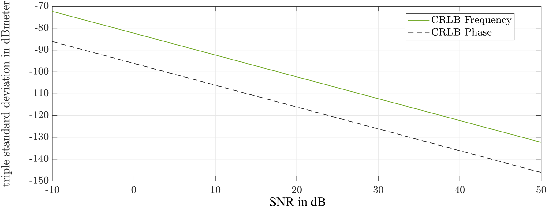
In Fig. 2 the standard deviations of the CRLB for the accuracy determination are shown once for the frequency and for the phase. The typical values for samples, bandwidth, and start frequency of the system were used for the calculations. Only the value for the SNR was varied. The limits of the phase evaluation are up to 15 dB lower than for the frequency evaluation.
Cramer–Rao limits for the accuracy of the estimator.
Simulation
In a next step, the behavior of the electromagnetic wave in a modeled plasma is simulated. As already mentioned, the Drude model is used to describe the motion pattern of electrons and ions in the plasma. The diameter of a reactor can be up to half a meter, which can lead to enormous simulation times at frequencies of 80 or 140 GHz and a wavelength of 3.75 and 2.14 mm, respectively. However, in order to determine the principle effects of the plasma, a simplified approach was pursued. For the first proof of concept, an overmoded waveguide is used in CST Microwave Studio. This waveguide has a width of a = 6 mm and a height of b = 3 mm. The background material is a perfect electrical conductor and the modeled plasma fills the entire waveguide. All boundaries are set to electric walls. Two symmetry planes are considered, and the waveguide is short-circuited at its end. A simulation run requires less than 1 min on a GPU, which allows numerous variations. The phase of the reflection coefficient S 11 is determined for different waveguide lengths and plasma states (Fig. 3).
Simulation results showing the phase of the reflection coefficient S 11 for four different plasma electron frequencies.
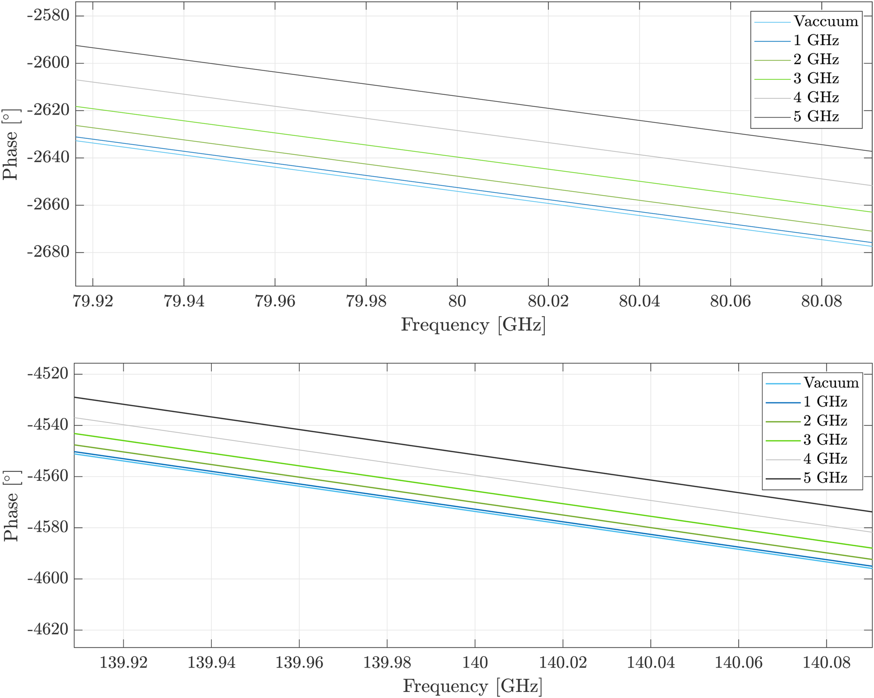
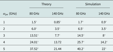
At the frequency range of 80 GHz, the real part of the permittivity will change from 0.9975 to 0.998 for a plasma frequency change from 1 to 5 GHz. This minor change in permittivity results in a minimal change in phase. For example, the phase difference, for a vacuum-filled waveguide and a plasma-filled waveguide with a plasma frequency of 3 GHz, is around 15$^\circ$ at a frequency of 80 GHz with a waveguide length of 100 mm. Using the 140 GHz system, the influence of the permittivity is much lower and the values for the phase difference decrease under unchanged conditions. However, the small wavelengths can be used to characterize small measurement setups. Furthermore at low densities, the phase of the wave is hardly influenced. This leads to the fact that highly precise measuring systems must be used. However, the increase in precision quickly reaches its limits. If the given conditions of the measurement scenario do not allow a greater wavelength, like in the potential monitoring of plasma jets [Reference Schutze, Jeong, Babayan, Park, Selwyn and Hicks18], the measurement effect can be enhanced by extending the measurement distance. For example, the phase difference doubles when the measurement distance is doubled. Table 1 shows the phase differences calculated from theory and from simulation. Equation (9) was used for the calculation of the theoretical values. The values of the theory and the simulation are in good agreement. The slight deviations of the values are due to the finite mantissa length of the numerical calculation. However, measurements in a real reactor will be significantly different from the simulation results because real plasmas are inhomogeneously distributed in reactors. In [Reference Hattenhorst, Pohle, Schulz, Rolfes and Musch19]–[Reference Lafleur, Charles and Boswell21] different plasmas in various reactors were measured with the MRP and the Langmuir probe. Thereby it became clear that the distribution strongly depends on the geometry of the reactor. However, it can be concluded that the electron density and thus, the plasma frequency of the plasma decrease toward the edges of the bulk.
Phase difference between a vacuum-filled waveguide and a plasma-filled waveguide
Measurements
Measurement setup
Figure 4 presents a possible radar-based measurement scenario in a CCP reactor. The basic setup of a CCP reactor consists of two electrodes placed on opposite sides. Usually one electrode is powered, while the second is connected to ground. Generally, a CCP is suitable for direct current (DC) as well as for radio frequency (RF) excitation. In this setup an excitation frequency of f = 13.56 MHz is applied with input power in the range of 10 up to 120 W. Two pumps behind a valve evacuate the reactor for operations in high vacuum with pressures typically ranging between 0.01 and 100 Pa. Finally, various gases can be inserted into the reactor to achieve different plasma behavior. The radar is mounted outside the reactor and a dielectric window is used to enable measurements of the plasma.
Schematic structure of the measurement setup.

In Fig. 5, the reactor provided for the measurements consists of a stainless steel ConFlat (CF) flange double crosspiece, which is used as a vacuum chamber. A vacuum pump is installed on the left side of the chamber via stainless steel connectors (c). A manual sliding valve can completely close the pumping branch. Furthermore, it is used to adjust the working range of the chamber pressure control. A TURBOVAC SL80 turbomolecular pump from Oerlikon Leybold Vacuum is used for the high vacuum. In order to be able to use this pump, a pre-vacuum must first be set, which is achieved by a DUO 016B rotary vane pump from Pfeiffer Balzer. For the measurements, pressures in the range of 3–7 Pa are applied. On the right-hand side of the double crosspiece, the flange has been fitted with an adjustable gas supply (d). The flow can be adjusted by means of a voltage-controlled inflow valve; this is approximately 330 sccm for this work. Two gases are available for the excitation of a plasma, first argon plasma with an optical emission at a range of 380–420 nm (violet) and oxygen plasma with an optical emission at a range of 575–585 nm (yellow). The upper flange was installed with the driven electrode ((b)+(e)) and the grounded electrode (f) protrudes from the lower flange. The rear flange is equipped with a metallic reflector (h). Opposite of the reflector, the flange has been equipped with a CF quick-closing door with an inspection glass. All reactor components are suitable for vacuum operation and are supplied by VACOM. The power is provided by the CESAR RF power generator of ADVANCED ENERGY, which has an integrated matching network, which matches the complex impedance of the plasma, including the feed line, to the 50 Ω internal resistance of the generator. It consists of an LC series resonant circuit between input and ground and a second LC series resonant circuit to the load. Both capacitances are individually adjustable in order to minimize the reflected power. In this work the feeded power of the generator is varied from 20 W to a maximum 120 W. The power below 20 W is not considered, because the plasma is not dense enough or might not ignite at all. Powers above 120 W lead to strong discharges that could damage the setup.
Measurement setup: (a) setup for reflector movement, (b) driven electrode, (c) connection to vacuum pump, (d) gas supply, (e) driven electrode, (f) grounded electrode, (g) dielectric window, (h) reflector, and (i) radar antenna.

Radar system
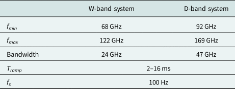
The radars used are based on a monolithic microwave integrated circuit in silicon germanium (SiGe) technology. In this work two radar sensors operating in different frequency ranges are applied. The frequency ramp of the first radar is in the range of 68–92 GHz and thus, has a bandwidth of 24 GHz. This system is further referred to as “W-band system” [Reference Pohl, Jaeschke, Scherr, Ayhan, Pauli, Zick and Musch22]. The second system has a bandwidth of 47 GHz and operates in the range from 122 to 169 GHz (Table 2). In this work, it is called “D-band system” [Reference Jaeschke, Bredendiek, Küppers and Pohl23]. Both modules have an integrated high frequency VCO, stabilized by a high precision external crystal reference source with a high precision phase locked loop. In both systems, the signal is fed to a microstrip line via bonding wires, then a coupling through the substrate passes the signal into a waveguide. Due to the large frequency difference between the two radars, the waveguide sizes for signal transmission differ. Furthermore, the D-band system has an integrated frequency doubler. To avoid overdriving of the system, variable amplifiers are used for both modules. The received intermediate frequency signal is then digitized and can be processed further. The modules are controlled, configured and supplied with power via USB interface.
Characteristics of the radar systems
Next, the phase noise of the two radar systems is compared with each other. Since they operate in different frequency ranges, the accuracy of the radars also changes. According to the CRLB, the D-band radar is slightly better in accuracy. To be able to prove this in the real setup, 1000 measurements were made on a constant target and evaluated. A standard deviation of 0.163$^\circ$ was obtained for the W-band system at 1000 measurements. For the D-band radar a standard deviation of 0.0442$^\circ$
 was calculated. The measurements of the 140 GHz system are better than those of the W-band system by a factor of 4, but both are perfectly suitable for the considered measurement scenario.
Results
Fixed target measurements can be performed with the setup used. Referring to Section “Plasma model” a plasma can be described as a frequency-dependent dielectric material. Consequently its effect on the speed of propagation and so on the TOF measurement can be detected, and the effect on the phase ϕ of the transceived electromagnetic signal can be evaluated:

with center frequency f c, vacuum speed of light c 0, relative effective permittivity $\varepsilon _{{r, eff}}$ , propagation length l, and additional propagation phase $\Phi _0$
 . The latter can be eliminated by reference measurements. To get an idea of the chemical impact of various gases on the plasma state, the measurements were taken in argon and oxygen plasmas. First of all, a variation of the input power is presented. Figures 6(a) and 6(b) present the results of a power variation in argon and oxygen plasmas for the W-band. For this purpose, 50 measurements were taken at each input power. Figure 7 presents the same measurement scenario monitored with the D-band system. The measurements in argon plasma were taken with an input power from 20 to 100 W. The measurements in an oxygen plasma also were taken in the same power range, but from a power of 100 W discharges appear at the driven electrode. To prevent further damages the measurement series with the D-band system has to be interrupted at the power input of 90 W. In both plasmas a recognizable change of the measured phase difference can be detected. Hence, a change of phase corresponds to a change in electron density of the plasma. Equation (28) shows the relation between input power and electron density in the plasma bulk:

with V being the volume of the chamber, E i the energy of the ions, K i an ionization constant. Thus, as the number of measurements increased, the input power was increased, leading to an increase in electron density. The change of the electron density leads to a change of the measured phase, clearly illustrated by a constant decrease of the measured phase in Figs 6 and 7.
Measured phase for different input powers (20–100 W) in argon (a) and oxygen (b) plasma with W-band system (50 measurements for one power level).
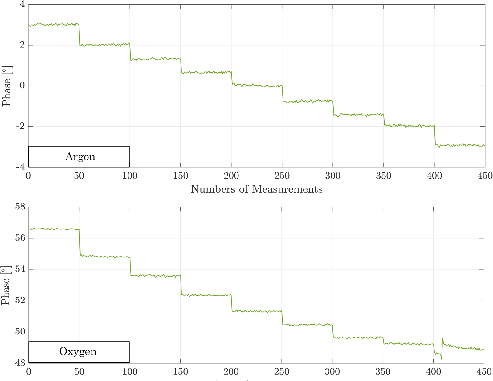
Measured phase for different input powers (20–100 W) in argon (a) and oxygen (b) plasma with D-band system (50 measurements for one power level).

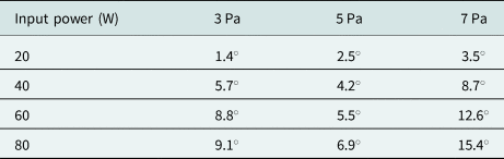
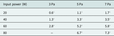
Furthermore, a change in pressure has an effect on the measured phase. Enlarging the pressure increase the electron density in the plasma bulk, which corresponds with a change of measured phase difference (Tables 3 and 4). Here, the phase differences for the D-band system are smaller than for the W-band system. Thus, the phase response behaves as described in the theory.
Phase difference for different pressures in argon plasma measured with the W-band system
Phase difference for different pressures in argon plasma measured with the D-band system
In Fig. 8, the activation process and thus, the associated transient and matching processes have been visualized. The first phase jump is due to switching on of the generator. The resulting plasma increases the phase velocity of the electromagnetic wave and a phase change occurs. While the plasma is not yet in equilibrium, the phase decreases. After a short time, the pressure of the chamber was increased from 2 to 4 Pa, a sharp increase in the phase is observable. After reaching 4 Pa, and the reflected power has to be adjusted with the matching network, this can be seen in the various peaks in the plot. Due to the pressure change, the plasma is out of equilibrium again. The settling process leads to the fact that the matching has to be readjusted.
Phase response in the switching-on process.

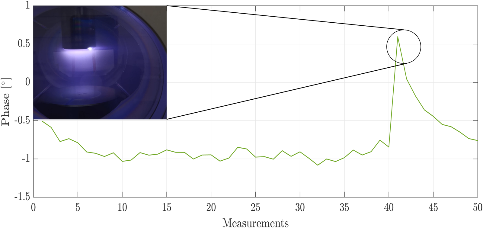
The last point to be considered is discharges at the electrode. If the feeding power is high, electrons will accumulate on the electrode over time. At a certain point, the electrodes discharge via a flash into the plasma bulk, recombining with the ions. Thus, the plasma becomes less dense, and the plasma frequency decreases, resulting in a deflection in the phase response. After the discharge, the recombination of ions and electrons stops, the external field accelerates free electrons, which generate new ions and electrons through collision processes until an equilibrium is reached. The whole process takes place in a very short time. Thanks to the high measuring rate of the sensors, this process can be displayed (Fig. 9).
Left: Phase response during a discharge. Right: Discharge at the driven electrode.
Conclusion
For the first time, plasma monitoring was performed and compared with an 80 and 140 GHz system. High-precision phase evaluation of the FMCW signal was used to enable industry-compatible monitoring of the plasma state. Depending on the TOF inside the plasma, a change of the effective relative permittivity can be supervised and detected. The relation between the TOF and the plasma density according to the Drude model is presented. The frequency behavior of the Drude model was confirmed using two frequency bands. Measurements in an argon and oxygen plasma demonstrate the applicability of this new approach. Special attention was paid to the possibility of controlling plasma processes. The potential of detection of smallest changes in the plasma state and the quasi-real-time measurements with high time resolution are features of this diagnostic method that makes it suitable for industry.
Acknowledgments
This work was supported by the Deutsche Forschungsgemeinschaft (DFG, German Research Foundation) under Project MARIE (287022738-TRR 196).
Conflict of interest
The authors declare none.
 Francesca Schenkel earned an M.Sc. in electrical engineering from the Ruhr-University Bochum, Bochum, Germany in 2020, where she is currently pursuing Ph.D. in electrical engineering at the Institute of Microwave Systems. Since 2020, she has been a research assistant with the Institute of Microwave Systems, Ruhr University Bochum. Her current research interests include radar systems, material characterizations, antenna design, and high temperature measurements.
 Christoph Baer earned the Dipl.-Ing. and Dr.-Ing. in electrical engineering from Ruhr University Bochum, Bochum, Germany, in 2009 and 2015, respectively. From 2006 to 2015, he was an RF research engineer with the Krohne Group. In 2016 he became academic councilor and lecturer and since 2022, he is academic senior councilor with the Institute of Electronic Circuits, Ruhr University Bochum. Dr. Baer has authored or co-authored more than 100 scientific papers and holds several patents. His current fields of research concern radar components and systems, humanitarian technology, antenna design, and microwave material characterization and synthesis. Dr. Baer is Vice-Chair of the IEEE Germany Section (2021–2022) and founder of the IEEE SIGHT Germany Section.
 Ilona Rolfes earned the Dipl.Ing. and Dr.Ing. in electrical engineering from Ruhr University Bochum, Bochum, Germany, in 1997 and 2002, respectively. From 1997 to 2005, she was with the High Frequency Measurements Research Group, Ruhr University Bochum, as a research assistant. From 2005 to 2009, she was a junior professor with the Department of Electrical Engineering, Leibniz University Hannover, Hannover, Germany, where she became the head of the Institute of Radio frequency and Microwave Engineering in 2006. Since 2010, she has been leading the Institute of Microwave Systems, Ruhr University Bochum. Her fields of research concern high-frequency measurement methods for vector network analysis, material characterization, noise characterization of microwave devices, and sensor principles for radar systems. Dr. Rolfes is a member of the Executive Committee of the IEEE MTT-S International Microwave Workshop Series on Advanced Materials and Processes. She is also a Board Member of the German IEEE MTT-AP Chapter and the German Commission for Electromagnetic Metrology of U.R.S.I. (International Union of Radio Science).
 Christian Schulz earned the Dipl.Ing. and Dr.Ing. in electrical engineering from Ruhr University Bochum, Bochum, Germany, in 2009 and 2016, respectively. From 2010 to 2016, he was a research assistant with the Institute of Microwave Systems, Ruhr University Bochum, where he has been a post-doctoral researcher since 2016. His current fields of research are concerned with 3-D electromagnetic field simulations, plasma diagnostics, radar systems, and antenna design. Dr. Schulz was a recipient of the IEEE Antennas and Propagation Society Doctoral Research Award in 2014 and the IEEE Microwave Theory and Techniques Society (IEEE MTT-S) Graduate Fellowship Award in 2015. In 2017, he received the Gert Massenberg Award for his doctoral thesis.


 Open access

