





1. Introduction
During severe weather conditions in the ocean, it is possible that water can overtop onto the deck of a vessel, travel across it and ultimately collide with equipment including prismatic structures. This impact may result in damage and/or operational problems. Consequently, there has been extensive research conducted to investigate the forces exerted by overtopping water (commonly referred to as green water) on topside structures. Most of this research has focused on vertical walls because some structures that may experience green water loading, such as bulwarks or elements of offshore platforms, have surfaces that can be approximated as vertical walls. For these structures, green water loads have been widely reported, including the ‘two-peak’ load time history and the influence of the location of the wall and the properties of the green water flow on the load impact and impulse (Barcellona et al. Reference Barcellona, Landrini, Greco and Faltinsen2003; Greco, Faltinsen & Landrini Reference Greco, Faltinsen and Landrini2005; Lu, Yang & Löhner Reference Lu, Yang and Löhner2012; Qin et al. Reference Qin, Tang, Xue, Hu and Guo2017).
Despite the focus on walls, topside structures can exhibit a wide variety of geometry and this has been shown to influence green water loads, albeit through a much smaller body of research. For instance, Buchner (Reference Buchner2002) carried out a series of model tests involving six distinct structures, each with the same impact area but a different geometry: a vertical wall (serving as a reference structure), a tilted wall, triangular structures with various semi-angles, a cylindrical structure and a square structure supported by triangular elements. The results indicated that the loads on these structures were significantly lower than the reference case of the vertical wall due to less momentum transfer and deflection away from the incident flow direction. Lee et al. (Reference Lee, Jeon, Nguyen and Yoon2016) also investigated the impact of green water on differently shaped structure protectors (rectangular, trapezoidal and cylindrical) through experimental analysis. By measuring the pressure on the deck and front faces of the structures, they discovered that the trapezoidal and cylindrical shapes experienced lower loads compared with the rectangular protector. In addition, the maximum pressure on the cylindrical protector was just below half that of the rectangular protector, thus indicating the importance of structural geometry on the maximum load.
Insight into how structural geometry influences load can also be gained from studies simulating dam break flow incident on a structure, which is an analogous problem to green water impacts on topside structures (Buchner Reference Buchner1995; Fekken, Veldman & Buchner Reference Fekken, Veldman and Buchner2000; Ryu, Chang & Mercier Reference Ryu, Chang and Mercier2007). Following this line of reasoning, several studies have compared dam break impacts on circular and square columns. Arnason, Petroff & Yeh (Reference Arnason, Petroff and Yeh2009), for example, measured the hydrodynamic forces resulting from a tsunami-like bore impact on vertical columns, finding that the force on a square column was nearly double that on the circular column of equal projected area. This result demonstrated the significant impact of column shape on the interaction between the bore and the structure and is broadly consistent with the findings of Lee et al. (Reference Lee, Jeon, Nguyen and Yoon2016). Wei et al. (Reference Wei, Dalrymple, Hérault, Bilotta, Rustico and Yeh2015) numerically replicated the experiments conducted by Arnason et al. (Reference Arnason, Petroff and Yeh2009) using smoothed particle hydrodynamics and, in addition to analysing the free surface and force on the cylinder, examined particle trajectories during the initial bore impingement on circular and square columns. Upon encountering the circular cylinder, particles approach and pass the structure smoothly, rising due to flow blockage and then falling due to flow expansion. Conversely, when interacting with the square column, particle trajectories are more varied, with some rising to high elevations and others moving toward the bottom or upstream, indicating the formation of a turbulent eddy due to flow–structure interaction. Mohd et al. (Reference Mohd, Kamra, Sueyoshi and Hu2017) also carried out a numerical investigation of dam break impacts on cylinders with square and circular cross-sections, and emphasized that the cross-sectional shape of the cylinder significantly influences the impact phenomena. More recently, Kamra et al. (Reference Kamra, Al Salami, Sueyoshi and Hu2019) conducted an experimental study assessing the dam break impact on a vertical cylinder placed on a dry bed in front of a downstream wall. Pressure measurements on the downstream wall indicated that a square cylinder removed streamwise momentum more effectively than the circular case, demonstrating again that the cross-sectional shape significantly influenced the nature of the impact.
To further explore the influence of geometry on loads, square cylinders have been rotated diagonally around their vertical axis relative to the incoming flow direction. Arnason et al. (Reference Arnason, Petroff and Yeh2009) conducted an experimental study of tsunami bore interactions with structures, finding that the force on a rotated square column did not exhibit spikes during the initial impact. This observation was confirmed by Wei et al. (Reference Wei, Dalrymple, Hérault, Bilotta, Rustico and Yeh2015) corresponding numerical simulation. When the square column was oriented diagonally, the run-up on its front side was smaller and the dynamic interaction between the bore and the square column was less intense. Shafiei, Melville & Shamseldin (Reference Shafiei, Melville and Shamseldin2016) explored tsunami bore impacts on a square cylinder with varying orientations relative to the flow direction. The study found that the streamwise bore impact force was slightly higher for the 0 $^\circ$ case, decreasing with increased orientation and reaching its lowest at force 45 $^\circ$. However, the quasi-steady flow hydrodynamic force after the initial impact peaked for the 30 $^\circ$ cases. Chuang et al. (Reference Chuang, Chang, Kaihatu, Cienfuegos and Mokrani2020) conducted an experimental investigation of the hydrodynamic force on a rectangular structure with different headings under tsunami bore impact. Contrary to Shafiei et al. (Reference Shafiei, Melville and Shamseldin2016) findings, the peak horizontal force was lowest at a 30 $^\circ$ heading rather than 45 $^\circ$. Wang et al. (Reference Wang, Santo, Taylor, Dai and Chan2023) explored the wave-in-deck loads on a solid cuboid deck model subjected to oblique transient focused wave groups at four distinct incident angles: 0 $^\circ$, 22.5 $^\circ$, 45 $^\circ$ and 67.5 $^\circ$. The study revealed that variations in the global longitudinal and transverse forces with changing incident wave angles are influenced by wave momentum destruction and impact area. Additionally, it was observed that larger relative incident wave angles lead to a reduction in maximum local longitudinal force, while simultaneously increasing both the maximum local transverse force and the maximum downward vertical force. Evidently, there are still ambiguities regarding the effects of structure orientation and further research is necessary.
The size of a structure relative to the depth of the incident bore can also influence the load it experiences. Arnason et al. (Reference Arnason, Petroff and Yeh2009) studied this effect, examining the influence of structure width relative to the incident water depth by simulating incoming bores with varying depth interacting with the same cylinder. They discovered that smaller bores had higher initial forces, while larger bores had greater overall impulse, concluding that the effect of the initial impingement by the bore front is at a maximum when the bore is small and the column is square. It is of interest to know if this same finding holds for other structure geometries.
Efforts to develop simplified methods to predict the force exerted on structures due to incident bore-like flows have been extensive. Cross (Reference Cross1967) studied the force on a vertical wall caused by a tsunami bore, estimating the force by considering only hydrodynamic forces and neglecting hydrostatic forces. Shafiei et al. (Reference Shafiei, Melville and Shamseldin2016) investigated the force on square cylinders with various orientations, estimating the force as a combination of hydrodynamic and hydrostatic forces. They established an empirical force coefficient for different scenarios. Wüthrich et al. (Reference Wüthrich, Pfister, Nistor and Schleiss2018) analysed the load on a square cylinder due to a tsunami bore, estimating the force as a hydrodynamic force with an appropriate resistance coefficient and flow properties obtained from undisturbed flow. Harish et al. (Reference Harish, Sriram, Schüttrumpf and Sannasiraj2021) estimated the load on a square cylinder by assuming the force took the form of a hydrostatic force, dependent on the hydrostatic pressure on both upstream and downstream sides of the cylinder. The predicted force aligned well with the measured force. Yu & Chu (Reference Yu and Chu2023) investigated the force resulting from roll waves impacting structures of different shape and orientation using two-dimensional (2-D) shallow water simulations. They demonstrate that the load on blunt objects (square and circular prism) is larger than pointed objects (triangular prism or rotated square) and indicate that the force coefficient reduces as the diameter of the object increases (relative to undisturbed flow depth). Collectively, these studies demonstrate that various methods have been developed for estimating the force on structures due to shallow water bore impacts. However, uncertainties still exist in these empirical predictive methods, as illustrated by the lack of a standard form to express the force. Further investigations are necessary to address these uncertainties and improve the understanding of this phenomenon.
Although quite a lot of studies have been conducted surrounding the effects of structure shape and orientation on shallow water bore impact, further investigations are necessary to gain a clearer understanding of the underlying physics. In this work, green water loads on structures with different shape, orientation angle and size are examined. To account for the complexity of fluid–structure interactions in the problem, both physical experiments and computational fluid dynamics (CFD) numerical models will be employed, utilizing the strengths of each method and compensating for any weaknesses. The remainder of this paper is organized as follows. First, the problem set-up, including the structure geometry, orientation, size and modelling methods are introduced. Next, the basic flow features observed in the experiments and simulations are described, with a focus on how these vary across different structural geometry and how they influence load. Finally, a simple theoretical model based on Newtonian flow theory is adopted to predict the force on structures and is compared with published and current results. The paper concludes with a summary of findings.
2. Methodology
2.1. Problem definition
A simplified arrangement is adopted to simulate green water and investigate its interaction with topside structures. The arrangement consists of a rigidly supported rectangular box (or hull) that is representative of a cross-section of a moored vessel or offshore structure (see figure 1a). Although this set-up does not capture vessel motions, it is similar to that adopted by Greco et al. (Reference Greco, Faltinsen and Landrini2005) and does allow for a realistic overtopping event to be generated. The box dimensions are based on a 1 : 64 scale model of a section of a floating production storage and offloading (FPSO) vessel, with a length of 1 m in the wave propagation direction, a width of 1.5 m (i.e. the full width of the flume) and a height of 0.476 m. The draft of the box is set to 0.426 m; this is larger than the instantaneous draft expected in actual conditions, but is convenient for simulating overtopping onto the vessel due to a reduced freeboard.
Definition sketch of green water interaction with on-deck structures, including structural shapes considered. An enlarged view of the on-deck area (indicated by the red dash box) is shown in lower part.

A crest focused wave group is used to overtop the box and generate the green water event. A focused wave group is an efficient way to model an extreme wave event in an irregular sea state (Jonathan & Taylor Reference Jonathan and Taylor1997; Zang et al. Reference Zang, Gibson, Taylor, Eatock Taylor and Swan2006). The underlying spectrum is JONSWAP with  $\gamma =3.3$ and the focus location for the group is set at the position of the leading edge of the box. Hence, this is the same focused wave group as that adopted in Gao et al. (Reference Gao, Draper, McCauley, Chen, Zhang, Wolgamot, Taylor and Cheng2023), with a linear amplitude of 0.12 m (in the absence of the box) and a peak period of 1.5 s. Figure 3 illustrates the surface elevation time history at the front of the box due to the incident wave group. It can be seen that the group results in five overtopping events, with the largest freeboard exceedance measuring just over 0.2 m. The base case green water flow is associated with this largest exceedance event. The water depth is set to 0.86 m, i.e. transitional water depth based on the peak wavenumber ( $k_pd = 0.459$). Although not representative of deep water, this water depth could be simulated in the flume and is sufficient to generate a repeatable wave crest and green water event.
A cube of side length 0.1 m is used as the base case topside structural shape. As highlighted in Krekel & Kaminski (Reference Krekel and Kaminski2002), FPSO modules exhibit geometric variability due to varying design objectives, but they often assume a cuboidal form. Additionally, cuboidal structures are a fundamental shape employed across numerous fluid–structure interaction problems, including previous studies relevant to green water flow (Buchner Reference Buchner2002; Lee et al. Reference Lee, Jeon, Nguyen and Yoon2016).
To investigate the effect of orientation, the centre of the obstacle is placed close to the centre of the rectangular box, so the front face of the obstacle is  $\sim$0.4 m from the front edge of the box (hull), with orientations of 0 $^\circ$, 15 $^\circ$, 30 $^\circ$ and 45 $^\circ$ (see figure 1b). The influence of structural shape is investigated through comparison to the circular 0.1 m diameter cylinder modelled in Gao et al. (Reference Gao, Draper, McCauley, Chen, Zhang, Wolgamot, Taylor and Cheng2023), and two additional circular cylinders with one half and one quarter of the diameter, respectively; this results in a range of relative structure sizes $D/\bar {h}$, where $\bar {h}$ is the time-average water depth during the overtopping event evaluated at the location of the structure (e.g. $\bar {h} = \overline {h(4H,t)}$; in figure 1).
2.2. Modelling methods
Since the interaction between green water events and topside structures is complex, both physical experiments and CFD models were adopted to model the scenario outlined in § 2.1.
The experiments were conducted in the 54 m long wave flume at the Coastal and Offshore Research Laboratory at The University of Western Australia. The wave flume is 1.5 m wide, 1.6 m tall and is equipped with a hinged flap paddle that is synchronized with the data acquisition system. A passive porous beach was placed at the other end of the flume to absorb transmitted waves. Figure 2 shows a sketch of the experimental set-up, which is identical to that used in Gao et al. (Reference Gao, Draper, McCauley, Chen, Zhang, Wolgamot, Taylor and Cheng2023). The rectangular box (or hull) was made of plywood and fixed to a steel frame attached to the flume floor to achieve a 0.05 m freeboard. The cube representing the base case topside structure was three-dimensionally printed from polylactic acid material with a mounting plate that allowed it to be rotated to achieve different orientations with a load cell fixed in place. Three additional circular cylinders were also printed and used. To measure the loads on the structures, a three-axis load cell (Forsentek F3G 100 N model) was placed at the base of the structure following a similar approach to that used in Gao et al. (Reference Gao, Draper, McCauley, Chen, Zhang, Wolgamot, Taylor and Cheng2023). Here the streamwise force  $F_x$ is along the wave propagation direction and the lateral force $F_y$ is perpendicular to $F_x$ in the horizontal plane, $F_z$ being the vertical force (not reported here). The dominant natural frequency of the combined structure-load cell system was found (by performing ‘hammer’ tests) to be 30 Hz in air and 20 Hz when the cube was submerged with water on the deck to a depth of 0.05 m.
Side view sketch of the overall deployment, including the location of the box and wave gauges (WGs) in the UWA flume. Dimensions are in metres. Not to scale. The details of the load cell mounting is shown in an exploded view for clarity.

To measure the incident wave group and the green water flow, respectively, three wave gauges were placed at distances of 3 m, 1 m, 0.01 m upwave of the front of the box, and four wave gauges were placed on top of the box at downwave distances of 0.1 m, 0.3 m, 0.6 m, 0.8 m away from the leading edge of the box. All wave gauges were located along the centreline of the wave flume.
To model the problem numerically, a fully nonlinear three-dimensional (3-D) wave tank was set up using OpenFOAM with the toolbox ‘waves2Foam’ to replicate the experimental set-up, again in a similar manner to that reported previously in Gao et al. (Reference Gao, Draper, McCauley, Chen, Zhang, Wolgamot, Taylor and Cheng2023). The incompressible Navier–Stokes equations are solved using a finite volume method without turbulence models and the volume-of-fluid method is used to capture the interface between air and water. The length of the numerical model domain is reduced to save computational cost, while the width and depth are kept the same as the experiment. The total length of the numerical wave tank (NWT) is  ${\sim }2.5\lambda _{p}$, while the distance between the wave inlet boundary and the leading edge of the box is ${\sim }1.5\lambda _{p}$. The peak wavelength $\lambda _{p}$ is 3.27 m. A wave relaxation zone is placed at both the inlet and outlet to avoid wave reflection. The set-up of the box and cylinder model, and the relative location of wave gauges, are kept the same as in the experiment. For the boundary conditions, the wave is generated at the left inlet vertical boundary by prescribing the wave velocity at the inlet boundary faces. The impermeable structures including the box and cylinder, the bottom, two sides and the right of the domain are modelled as no-slip walls, i.e. the velocity components normal and tangential to the surface are both set to zero. The top of the domain is modelled using a free atmosphere condition within OpenFOAM, allowing air to flow in and out freely and the water to flow out only.
The computational domain is divided into several regions and vertical layers. The domain is discretized on a structured mesh within each region and the mesh size is determined by convergence tests. The mesh in the wave propagation area, and the area around the structure, should be treated carefully. As the computational domain is very similar to that in Gao et al. (Reference Gao, Draper, McCauley, Chen, Zhang, Wolgamot, Taylor and Cheng2023), the mesh sizes in most of the domain are those used in that study, which were selected following the convergence test results reported there. For the mesh around the cube, the mesh topology around the structure has been altered. A mesh dependence study for this new topology has been undertaken, with details presented in the Appendix. The mesh adopted based on this study has 80 cells per side length around the cube.
In the numerical model, the experimental incident wave signal was recreated using an iterative method to account for the different upstream length of the NWT (following a similar approach to that outlined in Gao et al. Reference Gao, Draper, McCauley, Chen, Zhang, Wolgamot, Taylor and Cheng2023). The surface elevation at the front edge of the box recreated in CFD compared favourably to that measured in the experiments, shown in figure 3. Time  $t=0$ s corresponds to the instant when the incoming peak crest of the main wave group exceeds the deck level at the front edge of the box.
Comparison of surface elevation at the front edge of the box, measured with the box in place, between CFD and experiment. The blue dashed line indicates the deck level.

3. Green water impacting the structures
3.1. Example interaction: cube at 0 $^\circ$ heading

The results of green water impacting the 0 $^\circ$ heading cube are presented first to demonstrate the key flow features and how these related to the measured load. Supplementary movies are available at https://doi.org/10.1017/jfm.2024.1217 (1–4) for cubes with different orientations and show similar evolution of the flow during the green water event. The free surface evolution from the side and top, respectively, are shown in figures 4 and 5 for the cube with 0 $^\circ$ heading. Overall, it can be seen that both the CFD and experiments indicate a similar interaction. Starting at 0.25 s, it can be seen in both models that the overtopping flow plunges onto the deck, entrapping an air pocket. A bore then forms and travels across the deck, reaching the front of the cube at 0.37 s. This bore appears turbulent and unsteady in the experiment but exhibits a smoother, more uniform characteristic in the CFD simulation. The flow ultimately collides with the cube at around 0.4 s, and runs up the front face, creating a vertical sheet. This sheet collapses at $\sim$0.75 s, resulting in the formation of a reflected wave upstream of the cube. During the interaction, the wake flow is complex and characterized by a wake tail and locally dry deck downstream (see 0.75 s and 1.05 s in figure 5).


The flow features during the interaction are also illustrated using a vertical cross-section through the centre of the cube in figure 6. Upon the flow hitting the cube, the incoming flow can be seen to divert in two directions. The top layer of incident flow is diverted upwards, forming a vertical sheet (see 0.4 s, 0.45 s, 0.5 s in figure 6) within 0.1 s. This upward vertical sheet reaches its maximum height at around 0.6 s and then falls back due to gravity and mixes with the incoming flow, resulting in a complicated flow in front of the cube (see 0.75 s in figure 4). As the overtopping flow develops, the Froude number decreases to around 1, and approaches a subcritical flow. After this time, the reflected wave due to collapse of the vertical sheet travels upstream (see 0.85 s, 0.95 s, 1.05 s in figure 6). The lower layer of the incident flow is diverted downward, mixing with the entrapped air bubbles and forming a spinning vortex at the bottom of the cube (see 0.5 s, 0.55 s, 0.6 s, 0.65 s in figure 6). With reference to figure 11(a,e), this vortex then splits and diverts to the sides of the cube. Collectively, the diverted flow around the cube converges downstream of the cube, resulting in an oscillating ‘rooster tail’ wake with a localized dry deck immediately behind the cube.


The corresponding streamwise force on the cube is shown in figure 7, with the undisturbed flow information (water depth on deck, depth-averaged velocity and Froude number  $Fr=u/\sqrt {gh}$) at the front face shown in figure 8. The force has been low-pass filtered at 15 Hz to remove force oscillations in the experimental signal due to impact induced vibration of the structure-load cell system, and the CFD results have been similarly treated. The time history of the force on the cube is strongly related to the flow features described above. When the bore touches the front face of the cube at 0.37 s (e.g. figure 6), the streamwise force $F_x$ on the cube starts to increase. Since most of the incoming flow is diverted upwards, the incident momentum applies a significant horizontal load on the cube, which results in the force rising rapidly. After this initial interaction, the force keeps increasing due to continued flow diversion until it reaches a maximum at around 0.45 s in both the CFD and experiments. After that, it reduces gradually as the momentum in the incoming flow drops as the velocity, water depth and Froude number decrease. Collapse of the vertical jet results in a small secondary increase in the force, manifesting as a bump in the force time history at around 0.75 s–0.85 s. This is associated with the second peak in the ‘two-peak’ feature of green water load on structures (Barcellona et al. Reference Barcellona, Landrini, Greco and Faltinsen2003; Chen et al. Reference Chen, Taylor, Draper and Wolgamot2019). The force on the cube eventually drops back to zero as the overtopping is close to complete and the Froude number becomes subcritical. Aside from the collapsing jet, the gradual change in the force with the flow properties implies a quasi-steady process, in which the instantaneous force depends to first approximation on the instantaneous velocity and water depth measured at the location of the structure.


The (a) water depth  $h$, (b) depth-averaged velocity $u$ and (c) Froude number $Fr$ at the location of the upstream face of a 0 $^\circ$ cube without the cube present.

To further investigate the characteristics of the force, the impulse, computed as the force integrated over time (between 0.35 s and 0.65 s), and the maximum force (which is the largest streamwise force in time) are extracted in both CFD and experimental results and summarized in table 1. It can be seen that the average of the CFD predictions of the impulse on the cube are 12 % below the measured values whilst for the peak force, the CFD predictions are only 6 % lower than the measurements on the cube. Given the complexity of the impacting flows, this level of agreement is judged to be adequate. The force results for other structure configurations are reported in subsequent sections.
Summary of the impulse and maximum  $F_x$ for the cube and circular cylinder cases.

3.2. Influence of structure orientation
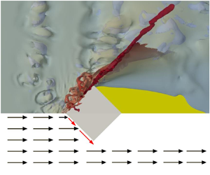
In the case of the cube with varying angles relative to the flow, figures 9 and 10 present the free surface profile at 0.55 s, the instant when the vertical sheet is close to the highest point, from CFD and experiment. These figures are complemented by streak lines of the flow interacting with the cube in figure 11 for four different orientations. The streak lines are generated from source points located at two different depths in the flow. Across these set of figures, it is evident that the incoming flow is split by the front edge facing the flow, with the deflected flow being the strongest at the 0 $^\circ$ heading. When the bore impacts the two inclined front faces of the oriented cube, a vertical sheet still forms on both faces, but the flow within the sheet is now diagonal across the inclined face rather than vertical for normal incidence. The run-up height decreases as the heading angle increases, resulting in reflected waves travelling upstream with different wavefront shapes depending on the orientation of the cube (see supplementary movies). As observed above for the cube at the 0 $^\circ$ heading, figure 11 shows that the flow in the upper layer is diverted up and the flow in the lower layer is diverted downward and away from the cube before mixing with the incoming flow and diverting around the two sides of the cube. Shortly thereafter, the dry deck downstream of the cube is covered by the colliding flow from both sides. The dry deck area varies for the different orientation scenarios. Overall, these findings demonstrate that the orientation of the cube significantly influences the green water flow dynamics and its interaction with the structure.
Snapshot of the flow around 0.55 s for the cube with four heading angles, from CFD. This is the instant when the vertical sheet is close to the peak height. Although the time taken for the vertical sheet to reach the peak height is not identical for different heading cubes, the current chosen instant comprises of four scenarios and can provide a direct comparison.

Photos of the flow around 0.55 s for the cube with four heading angles from experiment.

Streak lines around the cube at four different heading angles from the oblique view (a–d) and top view (e–h). Streak lines generated from the seed at  $0.3H$ height are shown at the left (a–d) and top (e–h) of the figure, while streak lines generated from the seed at $0.1H$ height are shown at the right/bottom, respectively.

The streamwise forces  $F_x$ on the cube with different headings are shown in figure 12 from both experiments and CFD. The 0 $^\circ$ heading cube experiences the largest force most of the time, but the force magnitudes among the other three headings are quite similar. The impulse decreases monotonically with increasing heading angle.
Time series of filtered streamwise force  $F_x$ and streamwise force divided by projected width $F_x/D'$ on the cube with different heading angles from CFD (a,c) and experiment (b,d).

As reported by Chuang et al. (Reference Chuang, Chang, Kaihatu, Cienfuegos and Mokrani2020), the structure becomes more streamlined as the angle increases and the force, normalized by the incoming momentum incident on the cube, decreases. However, the non-aligned cube has a larger projected width than the 0 $^\circ$ case. Considering the combination of these effects, the total streamwise force on cubes at different angles is not easily distinguishable, especially for non-zero headings. In contrast, the force $F_x$ divided by the projected width $D'$ illustrated in figure 12(c,d) shows a clear difference between various orientation cases, with this distinction being more evident in CFD results than experimental results. A comparison with the theoretical model in § 4 provides further insight into how these results align with the expected flow behaviour on the structure.
Regarding the force time history, the non-aligned cases do not exhibit a clear, sharp increase during the interaction. This is associated with the longer rise time for cases with larger rotation angles and occurs because when the bore hits the non-aligned cube, it first contacts the front edge and gradually moves along the face until reaching full contact. There is therefore a time delay between the flow reaching the front and back edges. Similar reductions in force for oriented cubes have also been observed by Arnason et al. (Reference Arnason, Petroff and Yeh2009) and Shafiei et al. (Reference Shafiei, Melville and Shamseldin2016).
Asymmetric orientation of the cube with respect to the incident flow will lead to asymmetrical flow distribution on the upstream faces of the cube, resulting in a lateral force,  $F_{y}$, on the cube. Figure 13 presents the time series of lateral force on the cube for various heading angles. It can be seen that there is negligible force for 0 $^\circ$ and 45 $^\circ$ orientations whilst the cubes oriented at 15 $^\circ$ and 30 $^\circ$ exhibit a lateral force of approximately 20 % of the streamwise force.
Time series of filtered lateral force  $F_y$ on the cube with different heading angles from (a) CFD and (b) experiment.

3.3. Influence of structure shape
Some typical flow features observed during green water flow interaction with the 0 $^\circ$ cube and circular cylinder are shown in figure 14. When the flow encounters the structure, a vertical sheet forms in both scenarios. However, the run-up of the vertical sheet is considerably higher in the case of the cube, as seen in the free surface profile in figure 14(a,b). With respect to the wake behind the structure, the cube produces a larger dry deck area and a more pronounced ‘rooster tail’, shown in figure 14(c,d). Subsequently to the collapse of the jet, a reflected wave travels upstream in both cases, yet they exhibit different wavefront shapes – with more curvature present in the circular cylinder case, as depicted in figure 14(e,f). Overall, the dynamic interaction between green water flow and the structure is less violent for the circular cylinder when compared with the cube of the same projected frontal area.
Typical flow features during green water flow interacting with the circular cylinder (a,c,e) and the cube (b,d,f); (a,b) run-up flow, (c,d) downstream wake, (e,f) upstream reflected wave. Time instants of these features are cross-referenced in figure 15.

Figure 15 illustrates the time history of the streamwise force  $F_x$ on both the cube and the circular cylinder, as obtained from CFD and experiment. It is evident that the overall force evolution is similar for the two configurations. Both exhibit a sharp force increase during the initial stage, followed by force undulations and a gradual decrease in the later stage. The magnitude of the force (in terms of the impulse and maximum force) on the circular cylinder is approximately half of that on the cube, which holds true for both CFD and experimental results. This observation is in line with the findings of force on circular and square columns, as reported by Arnason et al. (Reference Arnason, Petroff and Yeh2009) and Lee et al. (Reference Lee, Jeon, Nguyen and Yoon2016). It is worth noting that the difference in total streamwise force on the cube with varying heading angles is smaller than the difference when changing from a circular to a square shape.
Time series of filtered streamwise force  $F_x$ on the circular cylinder and the cube from CFD and experiment. Cross-markers indicate the time instants of typical flow features in figure 14.

The load reduction on the circular cylinder compared with the cube can be easily explained by the flow patterns shown in figure 14 (circular) and figure 4 (square). The flat upstream face of the cube deflects most of the incoming flow upwards with a greater change in the momentum. Similarly, the maximum force occurs after the initial impact during the increase stage for cubes, while it takes place at the initial impact for circular cylinders. These observations clearly demonstrate the importance of structure cross-section shape on the flow around and the force exerted on the structure.
3.4. Influence of structure size
For the circular cylinder, three different diameters have been investigated, with the cylinder height  $h$ remaining unchanged. Flow features at key time instants are shown in figure 16. It can be seen that as the relative size ( $D/\bar {h}$) decreases, the structure causes different disturbances to the flow, with the vertical sheet becoming smaller and reducing in peak height (noting that the overtopping event is identical for each cylinder). Following this, the reflected waves diminish in size, and the wake behind the cylinder becomes less prominent as the relative size reduces. These observations align with findings reported by Arnason et al. (Reference Arnason, Petroff and Yeh2009), supporting the relationship between relative cylinder diameter and the dynamics of green water flow interactions with the structure.
Snapshot of the flow at 0.55 s for the circular cylinder with three different sizes: (a,b)  $D/\bar {h}=4$, (c,d) $D/\bar {h}=2$, (e,f) $D/\bar {h}=1$, from CFD (a,c,e) and experiment (b,d,f).

To explore this relationship further, figure 17 displays the force on circular cylinders with different relative sizes from both the experiment and CFD. As expected, the smaller cylinder experiences smaller forces, and the same applies for the impulse. Interestingly, however, when the force is normalized by the projected width, which is  $D$ for a circular cylinder, all three cases are similar though not identical, as illustrated in figure 17(c,d), and this observation holds true for both the experimental and CFD results. Hence, the relative force is also influenced by the relative structure size.
Time series of filtered streamwise force  $F_x$ and normalized streamwise force $F_x/D$ on circular cylinders of different sizes from CFD (a,c) and experiment (b,d).

The circular cylinder with a smaller diameter exhibits a shorter rise time, and the interaction becomes less violent when the circular cylinder is smaller. Furthermore, the time at which the force first increases is different owing to the slightly different times when the bore hits the front face of the different diameter cylinders. The maximum force happens after the initial interaction in all cases, whilst the ‘second peak’ is only evident (at  $\sim$0.85 s) for the largest cylinder.
4. Predicting green water load
As discussed in the introduction, several models have been reported in the literature to predict the force on surface mounted cylindrical structures resulting from interaction with a bore. Most of these models, summarized in table 2, adopt one of the following three functional forms:
 \begin{gather} F_x=\tfrac{1}{2} \rho g D ( h^{2}_{f} - h^{2}_{r}), \end{gather}
 \begin{gather}F_x= C_{i} \rho u^{2} h D, \end{gather}
 \begin{gather}F_x = F_{hs} + F_{hd} =\tfrac{1}{2} \rho g D ( h^{2}_{f} - h^{2}_{r}) + \tfrac{1}{2} C_{D} \rho u^{2} h D. \end{gather}
Here  $\rho$ is fluid density, $g$ is gravitational acceleration, $D$ is the structure width, $u$ and $h$ are, respectively, the flow velocity and water height at the location of the structure measured without the structure present, $h_{f}$ and $h_{r}$ are, respectively, the water depth at the front and rear of the structure with structure present, $C_{D}$ is a drag coefficient and $C_{i}$ is a coefficient that some studies refer to as $C_{F}$ (force coefficient) while other studies write as $C_{R}$ (resistance coefficient). Equation (4.1) here represents a net hydrostatic force on the structure, (4.2) represents a hydrodynamic force and (4.3) is a combination of (4.1) and (4.2).
Published force formulations to predict forces on a structure in a shallow flow.

For the hydrostatic force formulation, the quasi-steady force acting on the structure can be estimated if the water height at the front and back sides of the structure are known (Sakakiyama, Matsuura & Matsuyama Reference Sakakiyama, Matsuura and Matsuyama2009; Ikeya, Akiyama & Iwamae Reference Ikeya, Akiyama and Iwamae2013; Qi, Eames & Johnson Reference Qi, Eames and Johnson2014; Ikeya et al. Reference Ikeya, Iwata, Okuda, Kikitsu, Ishihara, Hasegawa, Hashimoto and Obata2017; Harish et al. Reference Harish, Sriram, Schüttrumpf and Sannasiraj2021). Ikeya et al. (Reference Ikeya, Akiyama and Iwamae2013, Reference Ikeya, Suenaga, Fukuyama, Akiyama, Suzuki and Tateno2015) developed an analytical equation based on conservation of mass and momentum to estimate this height assuming either partial or complete reflection of the bore. Harish et al. (Reference Harish, Sriram, Schüttrumpf and Sannasiraj2021) provided a semi-analytical method to obtain  $h_{f}$ and $h_{r}$ for the incoming flow parameters ( $u$ and $h$) for certain Froude numbers and channel blocking ratios based on experimental results.
For the hydrodynamic force formulation, Cumberbatch (Reference Cumberbatch1960) assumed the force on the structure is proportional to the momentum per unit width in the incoming flow, such that the normalized force coefficient  $C_{F}$ is defined as the ratio of the force on the structure and the momentum flux. In that work $C_{F}$ is estimated as 2.1 and 1.4 for the 45 $^\circ$ and 22.2 $^\circ$semi-angle wedges, respectively. However, in most recent studies, the force on the structure is assumed to be of drag force form, expressed in terms of a resistance coefficient $C_{R}$, the effective frontal area $Dh$ and the dynamic pressure $1/2 \rho u^{2}$. The resistance coefficient $C_{R}$, similar to the classical drag coefficient $C_{D}$, was introduced to take account of the total streamwise force on the structure. Arnason et al. (Reference Arnason, Petroff and Yeh2009) studied the interaction of dam breaks with cylindrical and square structures, approximating the force on the structure as a hydrodynamic force with $C_{R} = 2$ for square structures and 1 to 2 for circular structures. Similar results have been reported by Cuomo et al. (Reference Cuomo, Shams, Jonkman and van Gelder2009), Nouri et al. (Reference Nouri, Nistor, Palermo and Cornett2010), Al-Faesly et al. (Reference Al-Faesly, Palermo, Nistor and Cornett2012), Wüthrich et al. (Reference Wüthrich, Pfister, Nistor and Schleiss2018).
For the combined formulation, Cross (Reference Cross1967) estimated the impact force on a vertical wall due to a tsunami bore using a force coefficient estimated based on the wedge angle of the incoming bore and a hydrostatic contribution based on the water depth in front of the wall. Shafiei et al. (Reference Shafiei, Melville and Shamseldin2016) estimated the force on a cube due to a tsunami bore using a drag coefficient in the hydrodynamic term dependent on the incident flow direction.
It is evident that all three formulations rely on empirical coefficients (e.g.  $C_{F}, C_{R}, C_{D}$ and/or some empirical representation of the elevation difference either side of the structure) to obtain accurate estimates of the load. Because of this, extrapolation of these models to different structural shapes or flow conditions is difficult. In the following a theoretical approach is taken to estimate the impact force that does not necessarily require empirical coefficients.
4.1. Newtonian flow theory
Newtonian flow theory is a well-known approach used for hypersonic flow problems to estimate the forces on a craft at hypersonic speeds (Anderson Reference Anderson2006). Newton theorized that the force on a surface due to a uniform stream of particles arises from the loss of momentum of the particles normal to the surface. For example, if a stream of particles with velocity  $V_{\infty }$ strike a flat surface inclined at an angle $\theta$, as illustrated in figure 18, Newton assumed that the normal momentum of the particles is transferred to the surface. Consequently, after colliding with the surface, the particles move along the surface, as depicted in figure 18(a), and the change in velocity component normal to the surface is equal to $V_{\infty } \cos \theta$. Flow–structure interactions of this type occur when the flow is hypersonic and produce a shock wave that is close to parallel to the plate (such that the deflected flow occupies a thin layer in front of the structure). In hypersonic flows this is most closely achieved at a large Mach number for a fluid with a ratio of heat capacities equal to unity, though Newtonian flow theory provides useful estimates outside these limits (Anderson Reference Anderson2006). The high-Froude-number flows occurring in green water may behave similarly – the upstream flow cannot adjust to the presence of a structure and the vertical projection of a fluid sheet upon impact plays the role of the shock, allowing the (incompressible) fluid to travel across the impacted surface in a thin layer.
Schematic of Newtonian flow theory.

Adopting Newton's assumptions, the mass flux of particles impacting a surface with area  $A$ can be estimated simply as $\rho V_{\infty } A \cos \theta$ (figure 18b). Thus, the time rate of change of momentum of this mass flux in the direction normal to the surface, which equals the normal force exerted on the surface, can be determined as the product of the mass flux and the change in normal velocity (e.g. Anderson Reference Anderson2006):
 \begin{equation} F_n= \rho V_{\infty} A \cos\theta \times V_{\infty}\cos\theta =\rho V_{\infty}^2 A \cos^{2}\theta. \end{equation}
Resolving this force in the incident flow direction then results in the predicted streamwise force on the structure:
 \begin{equation} F_x= \rho V_{\infty}^2 A \cos^{3}\theta. \end{equation}
Similarly, resolving this force perpendicular to the incident flow direction results in an estimate for the lateral force on the structure ( $F_y = \rho V_{\infty }^2 A \cos ^{2}\theta \sin \theta$ ).
Taking inspiration from this hypersonic theory, a model is developed to predict the force due to the supercritical green water flow incident on surface mounted structures. Considering first a cube oriented normal to the flow, figure 19 presents a vertical cross-section through the centre of the cube that is parallel to the incident flow. As seen in § 3, the incident flow in this plane is diverted upwards or downwards when it impacts the front face of this cube, resulting in almost complete loss of streamwise momentum. Furthermore, the tangential momentum of the fluid was seen to be small (especially near the centre of the cube) both before and after impact. Making use of these observations, the entire incident momentum flux is assumed to be converted into a streamwise force  $\rho u^{2} h$ per unit width, where the depth-averaged velocity and water depth are evaluated upstream of the cube just outside of the region where the vertical up flow is established (e.g. at a location $l< D$, as shown in figure 19). Hence, the initial part of the impact process, as the fluid sheet is projected upwards away from the impact region, is consistent with (4.5), taking $\theta = 0^\circ$. The subsequent downflow and the collapse of the fluid sheet are ignored.
Schematic of a vertical cross-section through the centre of the 0 $^\circ$ cube.

Fluid on both the upstream and downstream side of the structure may contribute additional hydrostatic force. In general,  $h_f$ and $h_r$ will differ from the undisturbed water depth, but the hydrostatic force per unit width will be of the order of $1/2 \rho g h^{2}$ or some fraction of this amount. The ratio of incident momentum flux to this hydrostatic force is therefore proportional to the square of the Froude number, implying that, for $Fr \gg 1$, the hydrostatic force is negligible. This is indeed the case for the flows and structures analysed in this work, for which the hydrostatic force impulse is at most 10 % of the total impulse across all experiments. Therefore, the hydrostatic force is ignored herein. Integrating the flux across the width of the 0 $^\circ$ cube structure (assuming a locally 2-D interaction across the entire width) leads to the force
 \begin{equation} F_x (t)= \rho u^{2} h D. \end{equation}
This force can vary in time due to changes in  $u(t)$ and $h(t)$; in this way, the force captures the quasi-static characteristics observed in § 3. This result is similar to the hydrodynamic model formulation presented in (4.2). However, a key difference here is that there is no empirical coefficient; the result is equal to the streamwise momentum loss rather than a form drag with an empirical drag or resistance coefficient. The forces on the structure in this scenario are dominated by inertial effects, originating in the loss of momentum from the flow upon impact. This differs fundamentally from drag-dominated scenarios, where forces arise from boundary layer dynamics and vortex shedding around the structure. It is reasonable to consider a drag model when the impacted body is fully immersed with water both in front and behind, so that a low pressure fluid wake is established. For most of the duration of the flow impacts considered here, there is either no water or at least an insignificant depth behind the body (see figures 4, 5 and 14). Hence, we consider that a momentum flux model is a more realistic description of the imposed force than Morison drag. However, there are fast flow problems where drag is important, such as a person standing in a fast shallow field (Cao et al. Reference Cao, Yuan, Chen, Zhao and Liu2021; Chen et al. Reference Chen, Yuan, Cao and Liu2021).
4.2. Rotated cubes and circular cylinders
The result given in (4.6) is now extended to cubes with different orientation angles  $\theta$. It is assumed again that flow incident on the cube is diverted along the two front faces (denoted $a$ and $b$ in figure 20) and contributes a force equal to the change in the normal component of the momentum flux. Resolving this force in the streamwise direction for both faces results in
 \begin{equation} F_{a, x} (t)+F_{b,x} (t) = \rho u^{2} h D \sin^{3}\theta + \rho u^{2} h D \cos^{3}\theta. \end{equation}
As expected, this result is entirely consistent with (4.6) when  $\theta = 0^\circ$. It is important to note in (4.7) that for non-normal orientations, the flow will not impact the entire front face simultaneously. Instead, the effective wetted length along each face will increase until the flow has reached all points on the upstream faces. Accounting for this transient leads to
 \begin{equation} F_{a, x} (t)+F_{b, x} (t) = \rho u^{2} h D D_{aw} \sin^{3}\theta + \rho u^{2} h D D_{bw} \cos^{3}\theta, \end{equation}
where
 \begin{equation} D_{aw}= \begin{cases} \dfrac{u_f t}{D \cos\theta}, & t< \dfrac{D \cos\theta}{u_f}, \\ 1, & t \ge \dfrac{D \cos\theta}{u_f}, \end{cases} \end{equation}
and
 \begin{equation} D_{bw}= \begin{cases} \dfrac{u_f t}{D \sin\theta}, & t< \dfrac{D \sin\theta}{u_f}, \\ 1, & t \ge \dfrac{D \sin\theta}{u_f}, \end{cases} \end{equation}
with  $u_f$ equal to the front velocity of the incident shallow flow (which may to first approximation be taken as $u$).
$u$).
A sketch of uniform flow impacting a cube with heading angle  $\theta$.

Using a similar procedure, it is also possible to calculate the force on a circular cylinder of radius  $R=D/2$. Discretizing the upstream half of the cylinder into small segments, and adopting Newtonian flow theory for each segment (shown in figure 21) leads to a streamwise contribution on each segment equal to
 \begin{equation} \text{d} F_x= \rho u^2 h R \,\text{d} \theta \cos^3\theta. \end{equation}
Sketch of uniform flow interacting with the circular cylinder.

Because the circular cylinder has a curved surface, when the flow strikes this surface and is assumed to remain in contact with it, the fluid element is also experiencing centripetal acceleration in the radial direction. To balance this centripetal acceleration and keep the fluid element moving along the surface, there must be a positive pressure gradient on the fluid element in the radial direction, which will contribute to the overall force on the structure. To estimate this force, the radial pressure gradient at a location around the cylinder (i.e. point  $A$ in figure 22) can be written as
 \begin{equation} \frac{\text{d}p}{\text{d}n} = \frac{\rho V^2}{R}, \end{equation}
where  $V$ is the local tangential velocity, $R=D/2$ is the radius of the cylinder and $n$ is a radial coordinate. Integrating both sides of this equation over the width of the fluid flow layer passing around the cylinder at point $A, \Delta n$ then gives
 \begin{equation} p_{2}-p_{s} = \int_{0}^{\Delta n} \frac{\rho V^2}{R} \, \text{d}n, \end{equation}
where  $p_{2}$ is the pressure just outside the flow layer (and equivalent to the pressure if centripetal flow was ignored) and $p_s$ is the pressure on the surface of the cylinder. Now, it follows that $\rho u \,\text {d} y = \rho V\, \text {d} n$ , so that the flow incident on the structure passes around the structure without loss of mass (see figure 22). Introducing this into (4.13) and noting that the tangential velocity at point $A$ must be $V=u\sin \theta$ to satisfy Newton's theory, results in
 \begin{equation} p_{2}-p_{s} = \int_{0}^{y+\Delta n \sin \theta} 2 \frac{\rho u^2}{D} \sin \theta \, \text{d}y. \end{equation}
Depth-integrated representation of high-Froude-number shallow flow interacting with a circular cylinder to illustrate the origin of the centripetal acceleration term.

As noted earlier, in hypersonic flow theory, the shock is assumed to coincide with the boundary of the structure (i.e.  $\Delta n \rightarrow 0$) so that all of the incident flow across the region $y$ must pass point $A$. Hence, the pressure on the surface of the cylinder can be written as
 \begin{equation} p_{s} = p_{2} - \int_{0}^{y+\Delta n \sin \theta} 2 \frac{\rho u^2}{D} \sin \theta \, \text{d}y = p_2 - \rho u^2 \int_{0}^{\theta} \sin\theta \cos\theta \, \text{d}\theta, \end{equation}
where the right-hand side follows from the fact that  $y=(D/2)\sin \theta$, so that $\text {d}y=(D/2)\cos \theta \,\text {d}\theta$. Evaluating the integral now gives
 \begin{equation} p_{s} (\theta) = p_{2}(\theta) - \tfrac{1}{2}\rho u^2 \sin^2\theta. \end{equation}
Noting that the incremental force in (4.11) is equivalent to  $p_2 R \text {d} \theta \cos \theta$ finally leads to a total force on each segment of the cylinder surface equal to
 \begin{equation} \text{d} F_x= \rho u^2 h R \, \text{d} \theta \cos\theta (\cos^2\theta- \tfrac{1}{2}\sin^2\theta), \end{equation}
where the first term results from the time rate of change in momentum and the second term originates from the centripetal acceleration (further discussion on this acceleration can be found in Anderson Reference Anderson2006, Chapter 3).
Integrating (4.17) over the upstream half of the cylinder then gives
 \begin{equation} F_x (t) = (\tfrac{2}{3}-\tfrac{1}{6})\rho u^2 h D= \tfrac{1}{2}\rho u^2 h D. \end{equation}
This is exactly half of the force on a cube of the same width oriented normal to the flow (4.6), which roughly matches the results obtained from CFD and experiment (shown in figure 15). Although some previous studies (i.e. Arnason et al. Reference Arnason, Petroff and Yeh2009; Lee et al. Reference Lee, Jeon, Nguyen and Yoon2016) also note that the force on a circular shape structure is nearly half of that on a square one, it is worth noting that the factor of one half here is not only because of the structural geometry change but also due to the centripetal acceleration of the fluid.
Finally, accounting for the transient increase in the wetted perimeter of the cylinder at the start of the impact, (4.18) can be generalized to
 \begin{equation} F_x (t) = \rho u^2 h R \int_{-\theta (t)}^{\theta (t)} (\cos^3 \theta - \frac{1}{2} \sin^2 \theta \cos \theta) \, \text{d} \theta, \end{equation}
where  $\theta (t)$ is the angle from the horizontal axis to the location where the flow front contacts the cylinder. It is estimated as
 \begin{equation} \theta (t)= \begin{cases} \arccos\left(1-\dfrac{2u_ft}{D}\right), & t<\dfrac{D}{2u_f}, \\ \dfrac{\rm \pi}{2}, & t \geqslant \dfrac{D}{2u_f}. \end{cases} \end{equation}
In the following section each of these theoretical results are compared with the numerical results.
4.3. Comparison to numerical results
4.3.1. Cubes
To enable a comparison between the theory and the numerical simulations, the undisturbed on-deck flow information at the location where the upstream face of the structure is placed is used to represent  $u$ and $h$ (i.e. $u = u (4H,t)$ and $h = h(4H,t)$). Using these time series, the comparison between the CFD simulated forces and Newtonian flow theory predicted forces are presented in figure 23 for the cubes with four different orientation angles.
The CFD simulated and Newtonian flow theory predicted time series of streamwise force  $F_x$ on the cube with different heading angles.

Overall, the force predictions based on Newtonian flow theory demonstrate good agreement with the CFD simulated forces. The rise in force during the initial stage is well represented and at later times (>0.45 s) agreement is also good, despite a continuously changing (but supercritical) Froude number. The predictions do not capture the small increase in force observed at approximately 0.85 s, because no account is made for the collapse of the vertical sheet, but otherwise they match the reduction in force reasonably well as the overtopping event ends. To compare the predicted and simulated impulse, table 3 presents these results integrated over the time between 0.35 s and 0.65 s. In all cases agreement is within 16 %, with the accuracy decreasing for larger orientation angles.
The CFD simulated and Newtonian flow theory predicted impulse in the flow direction integrated between 0.35 s and 0.65 s for the cube with different heading angles.

The agreement obtained in table 3 is despite the observation of 3-D characteristics in some of the interaction presented in § 3. For example, when the incoming flow encounters the structure, some flow near both edges of the front face is diverted away from the structure without impacting the front face. Consequently, some incident momentum flux is not transferred into a streamwise load, which is contrary to the assumptions in the Newtonian flow model. To investigate this aspect further, figure 24 presents pressure contours on the upstream face of the cube with different heading angles. For the cube oriented normal to the flow, the pressure distribution is close to uniform across the width of the structure, but there is a slightly higher pressure in the central region and a lower pressure towards the edges of the front face. This reduction in pressure at the edges is consistent with the observation of upstream flow diversion around the edges, resulting in a reduced momentum loss on the cylinder at these locations. There are also variations in pressure with height above the bed; this is consistent with the flow snapshot shown in figure 6 indicating voids and, hence, variable density with depth. It is useful to note that a large pressure region that is close to uniform across the front face of the structure is observed by Wang et al. (Reference Wang, Santo, Taylor, Dai and Chan2023) in their study of wave-in-deck loads on a solid cuboid deck model. Figure 25 illustrates the streamwise force per unit width obtained from the CFD and predicted by the Newtonian flow theory. Consistent with the observation in the pressure contour, the force per unit width calculated by the CFD method is largest near the middle and gradually diminishes towards the sides of the front edge, whereas the predicted force is constant. Despite this difference in shape, the agreement between the CFD and theory is otherwise impressive over the time interval shown.
Pressure on the upstream face(s) of the cube oriented at 0 $^\circ$, 15 $^\circ$, 30 $^\circ$ and 45 $^\circ$ (top to bottom row) from 0.36 s to 0.4 s.

The CFD simulated and Newtonian flow theory predicted streamwise force per unit length along the edge on cubes oriented at 0 $^\circ$, 15 $^\circ$, 30 $^\circ$ and 45 $^\circ$ (top to bottom row) from 0.36 s to 0.4 s. Horizontal axis represents the distance $s$ to the upstream edge normalized by the cube side length $D$. The vertical axis represents streamwise force per unit length along the edge. The total streamwise force on the cube can be reconstructed by integrating over the side length on the upstream face(s). Here $F_x = \int _{-1}^{1} F_{x}^{'}D \, \text {d}(s/D)$.

The pressure and streamwise force per unit width on the upstream face of cubes oriented at 15 $^\circ$, 30 $^\circ$ and 45 $^\circ$ have similar patterns, with some distinct variations, also demonstrated in figures 24 and 25. The pressure is largest on the most upstream faces for the 15 $^\circ$ and 30 $^\circ$ heading cases, whilst nearly identical on both faces for the 45 $^\circ$ heading case. In the initial moments, high pressure is focused in the small area where the bore contacts the cube. After that, the flow moves along the face until making full contact with the face in later time instants. This process is well captured for the 30 $^\circ$ and 45 $^\circ$ heading cases. After the flow fully contacts the cube faces, the pressure is mostly uniform across the width for all three heading cases. Similar phenomena were observed by Wang et al. (Reference Wang, Santo, Taylor, Dai and Chan2023) in the study of wave-in-deck loads on an oblique deck (45 $^\circ$ to the wave direction). In that case, the upstream corner of the deck redirects the flow to move tangentially along both faces of the deck, and positive pressure regions are concentrated primarily near the bottom of the deck. Regarding the force per unit width, the force is slightly overpredicted by the theory at most time instants for all three angled cases, and a pattern of higher force near the upstream end of the face and diminishing towards the downstream end is also observed. This phenomenon can also be attributed to side edge effects.
4.3.2. Circular cylinders
Figure 26 displays the comparison between the predicted force and CFD simulated force for the three different diameter cylinders. For all cases, the predicted force is slightly larger than the CFD simulated force. The smaller the cylinder, the more pronounced the overestimation. This trend is also observed in the impulse, as shown in table 4, with the overestimation being 14 %, 33 % and 52 % for the  $D/\bar {h} = 4$, 2 and 1 cylinder cases, respectively. It is worth mentioning that the centripetal correction in Newtonian flow theory is important for curved faces, such as the circular cylinder here. The predicted force without centrifugal correction would be up to 120 % overestimated for the smaller cylinder (e.g. $D/\bar {h}=1$).
The CFD simulated and Newtonian theory predicted time series of the streamwise force  $F_x$ on the circular cylinder with different sizes: (a) $D/\bar {h}=4$, (b) $D/\bar {h}=2$ and (c) $D/\bar {h}=1$.

The CFD simulated and Newtonian flow theory predicted impulse between 0.36 s and 0.65 s on the circular cylinder with different sizes.

As with the rotated cubes, the CFD simulated force per unit width on the circular cylinder was extracted across the width of the cylinder and compared with the Newtonian force per unit width. This comparison is illustrated in figure 28. It is evident that the force per unit width is largest in the middle section and gradually decreases towards the sides of the cylinder. Simultaneously, the force per unit width on the cylinder aligns better with that in the middle section, with the discrepancy increasing as it moves towards the sides. This observation holds true for most time steps shown here, indicating that the cylinder captures less momentum from the incoming flow as the observation point moves towards the sides and explains the overprediction of force by the Newtonian flow theory. There is a mismatch in the initial impact time in the CFD and Newtonian flow theory results, which arises from the different numerical set-ups: the CFD simulation is a fully 3-D case that includes the structure, while the case used to extract undisturbed on-deck flow information for the Newtonian flow theory force prediction is a 2-D simulation without the structure. However, as the total force time history, shown in figure 26(a), demonstrates good overall agreement between the two cases, the discrepancy in the initial impact time is of minimal practical significance. For the moment of initial impact in CFD, 0.37 s, the force per unit width is almost uniform across most of the width. This is believed to be due to the instantaneous large impact pressure. This can be further confirmed by the pressure contour on the cylinder, shown in figure 27, which exhibits a uniform pressure distribution across a small width with localized high-pressure areas. Afterwards, the pressure on the cylinder essentially presents a high-pressure pattern in the middle section at a certain level above the deck, gradually decreasing towards the sides. Near the edge, there is even negative pressure, resulting in a clear boundary line on the front face between the impact pressure and negative pressure areas. The importance of the centripetal acceleration in the prediction is shown by the mismatch of the predicted force per unit width without centripetal acceleration correction at 0.4 s (shown in blue in the last frame in figure 28).
Pressure on the upstream half-circumference face of the circular cylinder ( $D/\bar {h}=4$) from 0.36 s to 0.4 s.

The CFD simulated and Newtonian flow theory predicted force per unit circumference acting on the upstream half-circumference face of the circular cylinder. The total streamwise force can be reconstructed by integrating over the upstream half-circumference  $F_x= \int _{-{\rm \pi} /2}^{{\rm \pi} /2} F_{x}^{'} R\, \text {d} \theta$. The blue line in the 0.4 s plot shows the predicted force per unit width without the consideration of centripetal acceleration.

In addition to the current method for predicting the force on a structure, it is worth examining the applicability of some previously reported methods listed at the start of § 4 for the force estimation in the present flow–structure interaction case. Force formulations from Harish et al. (Reference Harish, Sriram, Schüttrumpf and Sannasiraj2021), Wüthrich et al. (Reference Wüthrich, Pfister, Nistor and Schleiss2018) and Shafiei et al. (Reference Shafiei, Melville and Shamseldin2016) were selected as representatives of each force form to estimate the force on a cube with a 0 $^\circ$ angle in the current case. For the force formulation from Harish et al. (Reference Harish, Sriram, Schüttrumpf and Sannasiraj2021), the empirical equations for estimating $h_f$ and $h_r$ were not directly applicable to the current case because the channel blockage ratio falls outside their range. However, since no water was observed behind the structure in the previous section, $h_r$ is assumed to be zero and $h_f$ is assumed to be the same as the water height from the undisturbed flow. For the force formulation from Wüthrich et al. (Reference Wüthrich, Pfister, Nistor and Schleiss2018), $C_R$ is set to 2 and the momentum flux per unit width in the undisturbed flow is utilized. Finally, to adopt the force formulation from Shafiei et al. (Reference Shafiei, Melville and Shamseldin2016), $h_r$ is set to 0 as no water was observed behind the structure, and $C_D$ is set to 1.65 based on their results. Here $h_f$ is determined using the water depth in the undisturbed flow.
The force on the 0 $^\circ$ angle cube can be estimated using the inputs from each method, as shown in figure 29, alongside CFD simulated and present Newtonian flow theory predicted results. It is evident that the hydrodynamic force form from Wüthrich et al. (Reference Wüthrich, Pfister, Nistor and Schleiss2018) shows identical results to the Newtonian model discussed here. In comparison, the combined form from Shafiei et al. (Reference Shafiei, Melville and Shamseldin2016) underpredicts by around 50 %, while the hydrostatic form from Harish et al. (Reference Harish, Sriram, Schüttrumpf and Sannasiraj2021) underpredicts by 90 %. Upon examining the flow conditions in each study, the Froude numbers of the flows are found to be 1.1, 1.7 and 2.7 in Harish et al. (Reference Harish, Sriram, Schüttrumpf and Sannasiraj2021), Shafiei et al. (Reference Shafiei, Melville and Shamseldin2016) and Wüthrich et al. (Reference Wüthrich, Pfister, Nistor and Schleiss2018), respectively, while it is above 2 most of the time in the current green water simulation. This difference is consistent with the hydrodynamic force of Wüthrich et al. (Reference Wüthrich, Pfister, Nistor and Schleiss2018) providing a good prediction while the other two methods that incorporate hydrostatic corrections, do not agree as well.
Streamwise force  $F_x$ on the 0 $^\circ$ cube obtained from CFD simulation and different prediction methods.

4.4. Variations in structure size and limitations of Newtonian flow theory
The inline force on a structure of given shape and orientation depend generally on the following parameters:
 \begin{equation} F_x= f(\rho, \nu, g, D, u, h, H). \end{equation}
Or, in terms of non-dimensional quantities
 \begin{equation} \frac{F_x}{\rho D u^2 h} = f\left(\frac{uD}{\nu}, \frac{u}{\sqrt{gh}}, \frac{D}{h}, \frac{H}{h}\right). \end{equation}
 The Newtonian flow theory presented in this section assumes that the first two dimensionless numbers in (4.22) (i.e. the  $uD/\nu$ and $u/\sqrt {gh}$ respectively) are sufficiently high that the flow is supercritical and behaves in the manner similar to that assumed in the Newtonian flow model. Across the range of CFD cases considered, this assumption appears to be reasonable, with good agreement between the theory and the numerical results at most times during the impulse, particularly within the observed range of Froude numbers, which typically exceed 2 and can reach as high as 9. Additionally, the Reynolds numbers in these simulations fall within the range of 50 000 to 200 000, so we assume that the results at practical scales are independent of Reynolds number. For more detailed information, please refer to figure 8. The last two dimensionless ratios $D/h$ and $H/h$ are not considered explicitly in the Newtonian flow theory, and are therefore explored further in this section using additional CFD simulations. As the water depth $h$ is time varying, the time-average water depth $\bar {h}$ during the overtopping event at the front face of the structure is used to calculate the relative structure size, $D/\bar {h}, H/\bar {h}$.
Firstly, the effect of  $D/\bar {h}$ was examined by simulating three additional cases for structures with different relative widths ( $D/\bar {h} =2$, 6, 8); the base case structure has $D/\bar {h} =4$. The Newtonian force on the structure was compared with the simulated force from CFD and is shown in figure 30. It is evident that the Newtonian theory predicted force has a significant deviation from the CFD simulated force for the narrowest structure case ( $D/\bar {h} =2$), whilst the agreement between the predicted force and CFD simulated force for the other three wider structures is relatively good. Similar conclusions can be drawn from the impulse results, as shown in table 5. The prediction ratio (Newtonian impulse/CFD impulse) is also presented. Overall, the comparisons between the theory and CFD are not unexpected, as the theoretical model assumes that the incoming flow is diverted uniformly along the face, and the flow streaming around the two sides is not accounted for by the narrow structure, leading to an overprediction of the force. As the $D/\bar {h}$ ratio increases, edge effects become less significant and the predicted force becomes closer to the simulated force. The results of the circular cylinders with three different diameters are given in figure 26 and table 4, respectively. In a similar fashion to the square cylinders, it is evident that the accuracy of the prediction increases with larger $D/\bar {h}$ when the width of the structure is relatively larger. This observation is consistent with the findings for the cube cases. The side effect and the loss of momentum are reduced with reductions in the local water depth. Based on the results presented here, the force prediction error is within 10 % when $D/\bar {h}$ exceeds 4, indicating that for relatively larger structures or shallower flows, the force on the structure is independent of this parameter.
The CFD simulated and Newtonian flow theory predicted streamwise force  $F_x$ on the structure with different widths: (a) $D/\bar {h} =2$, (b) $D/\bar {h} =4$, (c) $D/\bar {h} =6$ and (d) $D/\bar {h} =8$.

The impulse between 0.35 s and 0.65 s for the structure with different widths  $D/\bar {h}$ from CFD simulation and Newtonian flow theory prediction.

Regarding the effect of relative height  $H/\bar {h}$, it is expected that when the structure is tall enough, there will be no flow over the structure. Consequently, in the Newtonian model, potentially all the incident normal momentum should be transferred into a force on the structure. As the structure becomes shorter, flow over the top of the structure can occur, leading to the loss of some momentum in the incoming flow and an overprediction of force. To explore this trend, three additional cases with different $H/\bar {h}$ ratios have been simulated in CFD. The Newtonian force was compared with the CFD simulated force for different $H/\bar {h}$ scenarios, as shown in figure 31. Generally, all three cases exhibit good agreement between prediction and CFD results. The impulse between 0.35 s and 0.65 s, shown in table 6, reveals the level of agreement. When $H/\bar {h}$ exceeds 4, the error is within 10 %, suggesting that as the structure becomes taller, the force on the structure becomes relatively independent of this parameter, and the overprediction of force by the Newtonian method decreases.
The CFD simulated and Newtonian flow theory predicted streamwise force  $F_x$ on the structure with different heights $H/\bar {h}$: (a) $H/\bar {h} =2$, (b) $H/\bar {h} =4$, (c) $H/\bar {h} =6$ and (d) $H/\bar {h} =8$.

The impulse calculated between 0.35 s and 0.65 s for the structure with different heights  $H/\bar {h}$ from CFD simulation and Newtonian flow theory prediction.

5. Conclusions
Plunging-type green water events with air entrapment interacting with on-deck cylindrical structures of different shape configurations have been investigated using experiments and CFD simulations. A focused wave group was used to overtop the simplified vessel and generate the green water event, whilst detailed flow features and streamwise force on the structure were obtained from both methods, and good agreement between them was achieved. The characteristics of the flow features and force on the structure could be analysed in detail using simulated and experimental results. The strong agreement between the results indicates that CFD modelling is an effective tool for investigating the physics of green water events interacting with on-deck structures.
Consistent flow features were observed across all cases and structures, with some variations due to different structural configurations. When the green water flow encountered an on-deck structure, due to the supercritical nature of the flow, there was little apparent upstream influence from the presence of the obstacle. Upon contact with the structure, the flow divided into two layers. The upper layer was diverted upwards along the front face of the structure and formed a vertical sheet before collapsing downward. This indicates loss of the momentum in the incoming flow, which transfers into the force on the structure. The lower part of the flow, mixing with the collapsed flow, forms a vortex at the bottom, diverting to both sides of the structure and meeting at the back to create a complex wake. When the shape of the obstacle is changed from a square to a circular shape, the run-up height of the diverted upward flow is reduced, and the deflected flow on the front face is lessened due to the more streamlined shape. If the cube's orientation angle is altered to be non-aligned with the incoming flow, the flow is split by the front edge onto two faces, with the diverted flow travelling diagonally upward along the face. A spinning vortex still forms at the bottom of each face. For circular cylinders with different diameters, smaller cylinders cause relatively less disturbance to the flow.
The green water loads on structures appear to be amenable to quasi-static analysis despite the complex fluid–structure interaction features observed. Similar to the flow features, the time histories of the force on different structures exhibit similar patterns for various configuration scenarios, where there is an increase of force initially, before the force drops gradually over time. The force on the cube is approximately twice that of the circular cylinder with the same projected frontal area. For cubes with different orientation angles, the non-aligned cube deflects the flow less as the angle increases. Simultaneously, the projected width also increases. As a result, the cube with a larger rotation angle experiences a slightly smaller load, but this reduction is less significant than that caused by changes in the cross-section. For the cube in a non-symmetric orientation, significant sideways force is produced. For circular cylinders with different diameters, the force on the cylinder changes linearly with the structure size.
Due to the supercritical nature of the on-deck green water flow, a theoretical model based on the conservation of momentum was proposed to predict the force on the structure. This is based on the classical Newtonian approximation for hypersonic flow, here hypersonic is replaced by supercritical  $Fr \gg 1$. Analytical equations for the force on structures with different angles and sizes have been derived. The importance of the centripetal acceleration for the force on circular cylinders has been emphasized. Owing to the assumptions made in the model, the predicted force provides reasonable agreement with simulated results obtained via CFD despite the slight mismatch in initial impact timing. The accuracy of the proposed theoretical model was discussed concerning the relative structure width ( $D/\bar {h}$) and height ( $H/\bar {h}$). The predicted force is more accurate when the flow is supercritical (large $Fr$) and shallow (small $\bar {h}/D$), and the structure is taller (large $H/\bar {h}$). Despite its limitations, the model can provide an efficient prediction of the force on structures without the need for any empirical coefficients for practical use in early stage design.
In practice, the proposed theoretical model may serve as an effective early stage tool for predicting the force on topside structures in offshore facilities. For force estimation on various structures, only one CFD simulation of the green water overtopping event is required to gather on-deck flow information, such as velocity  $u$ and height $h$, at specific locations. This approach is far more efficient than repeating CFD simulations individually for different topside structures. Furthermore, since the model is simply based on momentum conservation, it is likely that it can be adopted for a wider variety of structural shapes than considered herein, as well as for groups of structures. Further research to investigate these scenarios would be worthwhile. Additional research has been undertaken to confirm the model's efficacy for structures in different locations (including different elevations above deck) and for different types of green water events (Gao Reference Gao2023).
Supplementary movies
Supplementary movies are available at https://doi.org/10.1017/jfm.2024.1217.
Funding
This work was supported by the ARC Industrial Transformation Research Hub for Offshore Floating Facilities that is funded by the Australian Research Council, Woodside Energy, Shell, Bureau Veritas and Lloyds Register (grant no. IH140100012). The support in resources provided by the Pawsey Supercomputing Center with funding from the Australian Government and the Government of Western Australia is acknowledged. L.C. also thanks the support by NSFC (grant no. 52001053) and the Natural Science Foundation of Liaoning Province (grant no. 2021-KF-16-03). H.A.W. acknowledges support from an Australian Research Council (ARC) Early Career Fellowship (DE200101478) and Shell Australia.
Declaration of interests
The authors report no conflict of interest.
Appendix. Mesh convergence study
Since the cube has sharp edges at the corners, the mesh topology used for a circular cylinder in Gao et al. (Reference Gao, Draper, McCauley, Chen, Zhang, Wolgamot, Taylor and Cheng2023) is not generally suitable. In order to achieve accurate results, another mesh independence study was conducted for the cube. The mesh upstream and around the structure is the most important area. The same upstream mesh as that used in Gao et al. (Reference Gao, Draper, McCauley, Chen, Zhang, Wolgamot, Taylor and Cheng2023) was adopted, whilst the mesh topology was altered and the mesh size near to the structure was varied to give different numbers of cells along one side of the cube. In total, five sets of mesh were adopted as listed in table 7, and used to simulate the green water impact on a cube rotated to have a 15 $^\circ$ heading. To indicate the topology, the coarsest, medium and finest mesh are illustrated in figure 32. The resulting simulated force on the cube is compared in figure 33. It can be seen that meshes 3, 4 and 5 show similar force time histories while meshes 1 and 2 show a clear spike in the initial time history. The impulse between 0.35 s and 0.65 s is also shown in table 7. The impulse is similar in meshes 3 to 5, which indicates some level of convergence, although it is not monotonic. Given the complexity of the fluid–structure interaction investigated here, the smallest mesh size (mesh 5) has been used for the study.
The impulse between 0.35 s and 0.65 s on the cube by using different meshes.

The mesh topology used for a 15 $^\circ$ heading cube. Coarsest (mesh 1), medium (mesh 3) and finest (mesh 5) mesh from left to right.

Time series of the streamwise force on the cube by using different meshes.


 Open access

