





1. Introduction
The rupture of freely suspended liquid films has been extensively researched, with various studies focusing on different aspects of the process. While many studies investigate the mechanisms preceding the rupture (Thoroddsen, Etoh & Takehara Reference Thoroddsen, Etoh and Takehara2006; Vernay, Ramos & Ligoure Reference Vernay, Ramos and Ligoure2015; Lo, Liu & Xu Reference Lo, Liu and Xu2017; Duchemin & Josserand Reference Duchemin and Josserand2020 Oratis et al. Reference Oratis, Bush, Stone and Bird2020; Poulain & Carlson Reference Poulain and Carlson2022; Sprittles et al. Reference Sprittles, Liu, Lockerby and Grafke2023), others focus on the mechanisms following it – notably, the rupture of a liquid film produces a large number of droplets, which can be detrimental or beneficial depending on their application (Debrégeas et al. Reference Debrégeas, Martin and Brochard-Wyart1995; Villermaux Reference Villermaux2007; Lhuissier & Villermaux Reference Lhuissier and Villermaux2009; Bird et al. Reference Bird, De Ruiter, Courbin and Stone2010; Feng et al. Reference Feng, Roché, Vigolo, Arnaudov, Stoyanov, Gurkov, Tsutsumanova and Stone2014; Villermaux Reference Villermaux2020; Jiang et al. Reference Jiang, Rotily, Villermaux and Wang2022, Reference Jiang, Rotily, Villermaux and Wang2024). This is crucial in various fields, including disease transmission, aerosol formation, spray drying nanodrugs, oil dispersal, inkjet printing and spray coating, which in turn affect health, climate and many industrial applications.
Film rupture can be classified into two categories: single-hole rupture and multiple-hole rupture. In a single-hole rupture, only one hole forms within the time scale of the film’s complete collapse (Debrégeas et al. Reference Debrégeas, Martin and Brochard-Wyart1995; Bird et al. Reference Bird, De Ruiter, Courbin and Stone2010; Feng et al. Reference Feng, Roché, Vigolo, Arnaudov, Stoyanov, Gurkov, Tsutsumanova and Stone2014; Jiang et al. Reference Jiang, Rotily, Villermaux and Wang2022). This scenario is often observed when an external object punctures the film, such as bursting a bubble with a needle. In contrast, multiple-hole rupture involves the formation of several holes either simultaneously or in close succession. This typically occurs in thin, unstable films, where holes nucleate spontaneously at different points. Multiple-hole rupture is likely when the liquid contains a dispersed phase, such as emulsions, air bubbles or solid suspensions. It is also likely to occur when the liquid film is expanding and thus thinning rapidly. Examples include bag breakup of a falling raindrop (Villermaux & Bossa Reference Villermaux and Bossa2009), rapid expansion of a bubble (Vledouts et al. Reference Vledouts, Quinard, Vandenberghe and Villermaux2016), bursting of a surface bubble (Qian et al. Reference Qian, Yang, Zhang, Feng and Li2023), corona splash (Thoroddsen et al. Reference Thoroddsen, Etoh and Takehara2006; Aljedaani et al. Reference Aljedaani, Wang, Jetly and Thoroddsen2018), fan spray nozzle (Dombrowski & Fraser Reference Dombrowski and Fraser1954; Lhuissier & Villermaux Reference Lhuissier and Villermaux2013), drop impact on a small surface (Vernay et al. Reference Vernay, Ramos and Ligoure2015), drop impact on a superhydrophobic substrate (Kim et al. Reference Kim, Wu, Esmaili, Dombroskie and Jung2020), and the trapped air film of drop impact onto a pool (Thoroddsen et al. Reference Thoroddsen, Thoraval, Takehara and Etoh2012) or solid surfaces (Li, Vakarelski & Thoroddsen Reference Li, Vakarelski and Thoroddsen2015; Langley et al. Reference Langley, Li, Vakarelski and Thoroddsen2018).
The multiple-hole rupture cannot be explained simply as a superposition of single-hole ruptures, because the holes interact with one another. Building on earlier studies (Dombrowski & Fraser Reference Dombrowski and Fraser1954; Lhuissier & Villermaux Reference Lhuissier and Villermaux2013), significant progress has been made recently in understanding hole–hole interactions on planar films (Néel et al. Reference Néel, Lhuissier and Villermaux2020; Agbaglah Reference Agbaglah2021; Tang, Adcock & Mostert Reference Tang, Adcock and Mostert2024). When two holes collide at high Weber number, a transverse lamellar sheet emerges and breaks into smaller droplets in a process known as rim splashing (Néel et al. Reference Néel, Lhuissier and Villermaux2020; Tang et al. Reference Tang, Adcock and Mostert2024). The droplet formation is closely related to the ligament growth, which has been studied in detail recently on expanding liquid sheets (Wang et al. Reference Wang, Dandekar, Bustos, Poulain and Bourouiba2018; Wang & Bourouiba Reference Wang and Bourouiba2021).
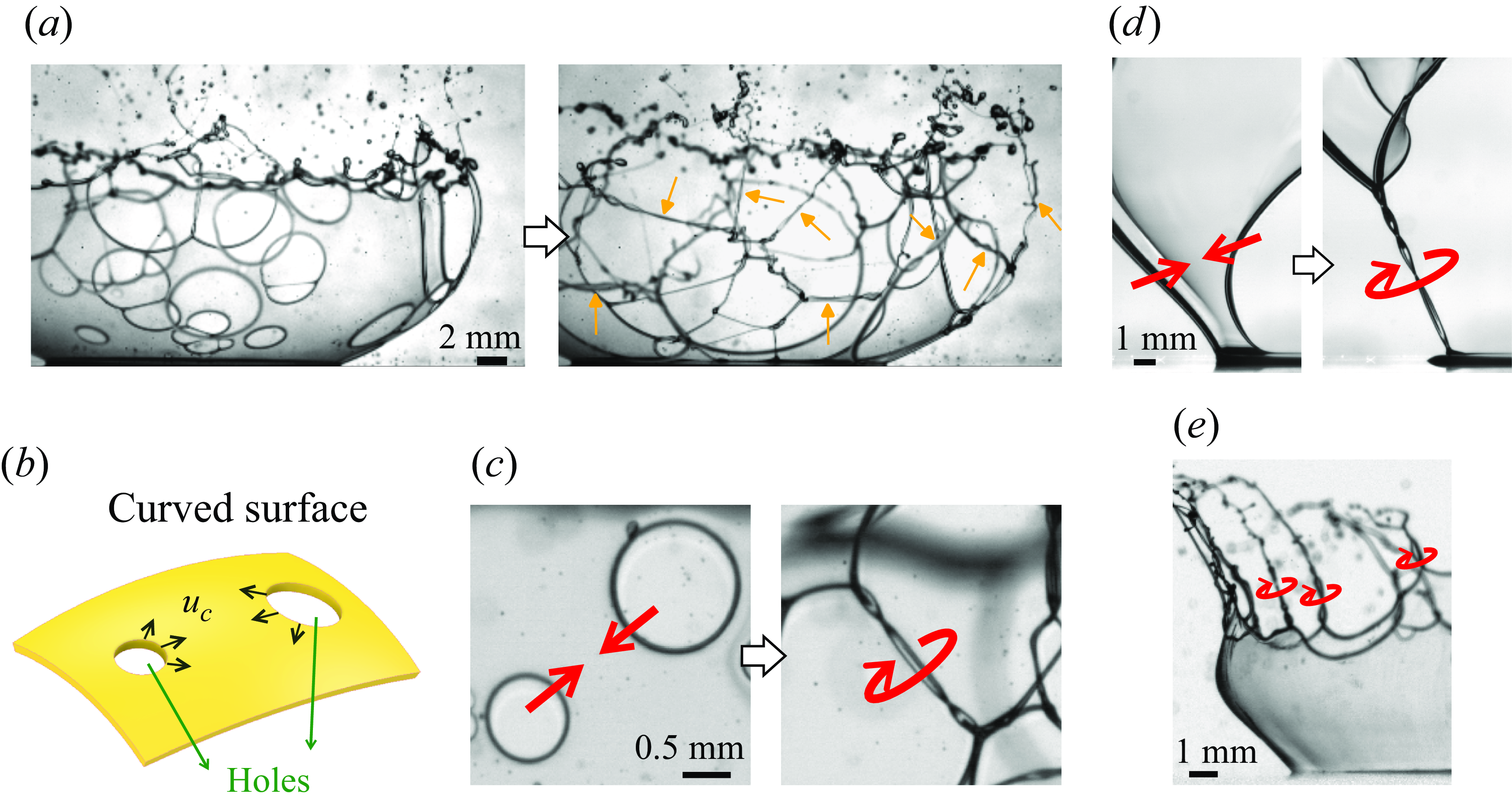
Examples of spinning twisted ribbons appearing on rupturing curved liquid sheets under various scenarios: (a–c) meeting of two expanding holes, (d) meeting of two edges, (e) spikes of the crown splash. See supplementary movies 1–4. (b,c) A drawing and magnified view for the case of (a) showing two holes expanding at a constant speed $u_{c}$
. In (d) and supplementary movie 3, the highest observed spinning frequency is 5200 Hz.
$u_{c}$
. In (d) and supplementary movie 3, the highest observed spinning frequency is 5200 Hz.
While the mechanism that triggers the film rupture is not the focus of this study, it is an interesting topic that remains under active research and is likely to vary depending on specific circumstances. Possible explanations include, but are not limited to, the Rayleigh–Taylor instability, turbulence within the film, presence of tiny air bubbles trapped inside, and collisions with surrounding fine droplets of lower surface tension (Thoroddsen et al. Reference Thoroddsen, Etoh and Takehara2006; Vledouts et al. Reference Vledouts, Quinard, Vandenberghe and Villermaux2016; Aljedaani et al. Reference Aljedaani, Wang, Jetly and Thoroddsen2018; Bang et al. Reference Bang, Ahn, Yoon and Yarin2023; Stumpf et al. Reference Stumpf, Roisman, Yarin and Tropea2023). The probability of hole formation in turbulence-triggered rupture has been previously derived (Bang et al. Reference Bang, Ahn, Yoon and Yarin2023; Stumpf et al. Reference Stumpf, Roisman, Yarin and Tropea2023).
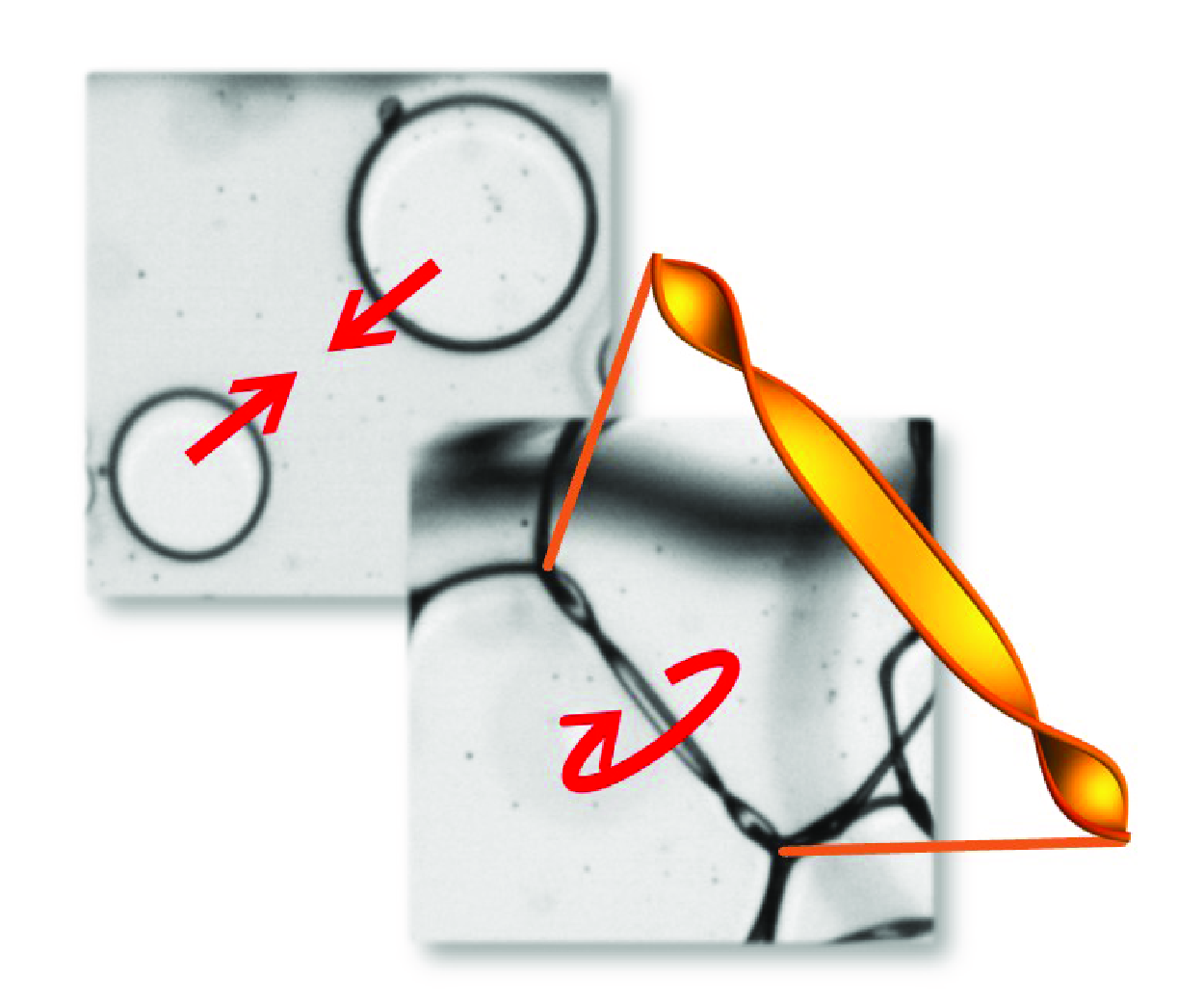
In this study, we reveal a phenomenon that is unique to curved films: when two holes meet, the liquid film evolves into a spinning twisted ribbon, as shown in figure 1(a–c) and supplementary movies 1 and 2 available at https://doi.org/10.1017/jfm.2025.10299, and then droplets are ejected due to the spinning. The ribbon is a tiny helicoid-like structure ( $\sim$
100
$\sim$
100 $\unicode{x03BC}$
m wide) that spins at a high speed (
$\unicode{x03BC}$
m wide) that spins at a high speed ( $\sim$
5000 Hz). It can, therefore, be easily overlooked without careful inspection. Nevertheless, this phenomenon may have been observed as early as 1954 by Dombrowski & Fraser (Reference Dombrowski and Fraser1954), who wrote that ‘At the instant before coalescence of the two rims, the ribbon of liquid between them may twist’. To the best of our knowledge, however, the twisted ribbon has not been studied until now. Besides the meeting of two holes, the twisted ribbon is a general feature that also emerges in various similar systems, such as the meeting of two edges (figure 1
d and supplementary movie 3) and the spikes in corona splash (figure 1
e and supplementary movie 4). The analysis is based on experiments of multiple-hole rupture in corona splash; we explain the formation and evolution of spinning twisted ribbons. The underlying principles are likely applicable to other systems where twisted ribbons appear.
$\sim$
5000 Hz). It can, therefore, be easily overlooked without careful inspection. Nevertheless, this phenomenon may have been observed as early as 1954 by Dombrowski & Fraser (Reference Dombrowski and Fraser1954), who wrote that ‘At the instant before coalescence of the two rims, the ribbon of liquid between them may twist’. To the best of our knowledge, however, the twisted ribbon has not been studied until now. Besides the meeting of two holes, the twisted ribbon is a general feature that also emerges in various similar systems, such as the meeting of two edges (figure 1
d and supplementary movie 3) and the spikes in corona splash (figure 1
e and supplementary movie 4). The analysis is based on experiments of multiple-hole rupture in corona splash; we explain the formation and evolution of spinning twisted ribbons. The underlying principles are likely applicable to other systems where twisted ribbons appear.
2. Experimental methods
We observe the ruptures appearing in the corona splash, induced by the high-speed impact of viscous drops on glass slides coated with a thin lower-viscosity liquid film. In corona splash, the spreading liquid sheet lifts upwards away from the substrate to form a ‘crown’, which is essentially a curved thin film, as shown in figure 1(a) and supplementary movie 1. We focus only on the film ruptures, rather than on the splashing as a whole, which is a complex phenomenon still under active research (Thoroddsen et al. Reference Thoroddsen, Etoh and Takehara2006; Yarin Reference Yarin2006; Aljedaani et al. Reference Aljedaani, Wang, Jetly and Thoroddsen2018; Sanjay et al. Reference Sanjay, Lakshman, Chantelot, Snoeijer and Lohse2023; Sykes et al. Reference Sykes, Cimpeanu, Fudge, Castrejón-Pita and Castrejón-Pita2023; Khan, Jin & Yang Reference Khan, Jin and Yang2024; Tian et al. Reference Tian, Aljedaani, Alghamdi and Thoroddsen2024).
The drop shape is flattened due to aerodynamics stress at high falling speeds. The drops impact at speeds $U$
= 6.4–8.1 m s−1, with vertical diameters
$U$
= 6.4–8.1 m s−1, with vertical diameters $D_V$
= 2.3–3.7 mm and horizontal diameters
$D_V$
= 2.3–3.7 mm and horizontal diameters $D_H$
= 3.5–4.8 mm. The drops are prepared using either silicon oil or glycerol–water mixtures, with viscosities of 30–50 cSt and surface tensions of 21 or 65 mN m−1. The corresponding ranges of the drop-impact Weber, Reynolds and Ohnesorge numbers are
$D_H$
= 3.5–4.8 mm. The drops are prepared using either silicon oil or glycerol–water mixtures, with viscosities of 30–50 cSt and surface tensions of 21 or 65 mN m−1. The corresponding ranges of the drop-impact Weber, Reynolds and Ohnesorge numbers are $We=\rho D U^2/\gamma = 5170{-}12\,000$
,
$We=\rho D U^2/\gamma = 5170{-}12\,000$
, $\textit{Re}=\rho D U / \mu = 400{-}1200$
and
$\textit{Re}=\rho D U / \mu = 400{-}1200$
and $Oh= \mu / \sqrt {\rho D \gamma } = 0.09{-}0.19$
, respectively, where
$Oh= \mu / \sqrt {\rho D \gamma } = 0.09{-}0.19$
, respectively, where $\rho$
,
$\rho$
, $\gamma$
,
$\gamma$
, $\mu$
and D are the density, surface tension, viscosity and volume-equivalent diameter of the drop.
$\mu$
and D are the density, surface tension, viscosity and volume-equivalent diameter of the drop.
The coated liquid film on the glass slide consists of either 1.5 cSt silicon oil with a thickness of 53 µm or ethanol with a thickness of 35 µm. The thickness is calculated from the volume of the deposited liquid and the area of the substrate. As the film coated on the solid substrate is very thin, following the original spray, the crown of the corona splash (i.e. the curved film) originates from the liquid in the drop, rather than from the liquid film coated on the glass slide (Thoroddsen et al. Reference Thoroddsen, Etoh and Takehara2006). This is verified in our experiments by dying the drop, as presented in Appendix A. Therefore, the liquid properties of the substrate-coated film do not affect the ruptures directly.
The crown of the corona splash is a curved liquid thin film. The film thickness $\delta$
is deduced from the measured speed by inverting the Taylor–Culick relation. The film thickness varies slightly across different samples as the crown expands and thins over time, with a mean of
$\delta$
is deduced from the measured speed by inverting the Taylor–Culick relation. The film thickness varies slightly across different samples as the crown expands and thins over time, with a mean of $7.8 \pm 1.3$ $\unicode{x03BC}$
m for the silicone oil and a range of 10–40
$\unicode{x03BC}$
m for the silicone oil and a range of 10–40 $\unicode{x03BC}$
m for the glycerol–water mixture.
$\unicode{x03BC}$
m for the glycerol–water mixture.
We record the impact processes using one or two high-speed cameras, with a frame rate of 31 000 frames per second and a resolution of 14.5 µm pixel−1. On a curved surface, the plane of ruptures may not be parallel to the image plane of the camera, leading to parallax errors in length (Stumpf et al. Reference Stumpf, Roisman, Yarin and Tropea2023). We correct the parallax error on the curved surface by using the method outlined in Appendix B. To focus on the dynamics of the ruptures, we present the data in a moving inertial frame that offsets the linear motion of the liquid film.
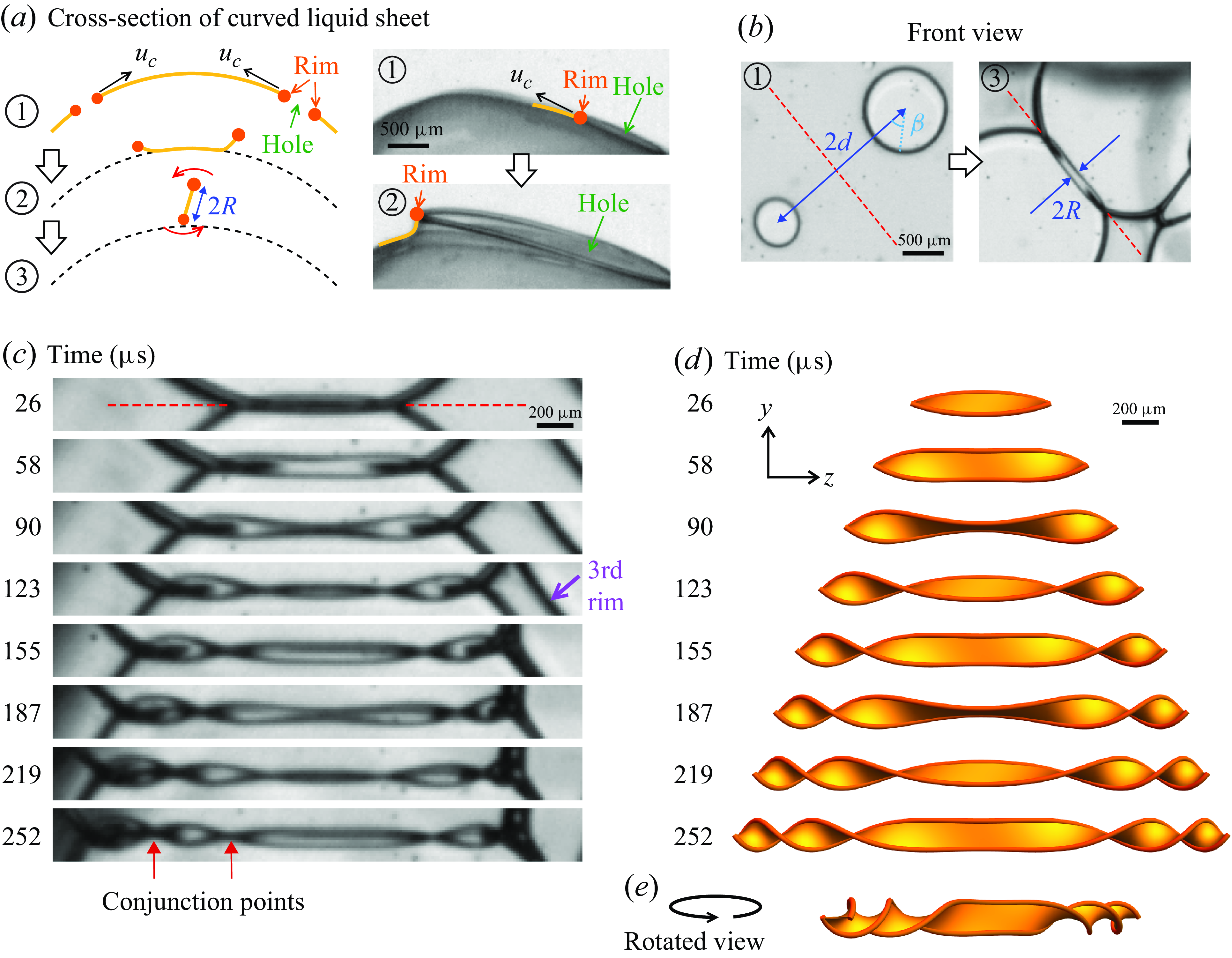
The formation mechanism of the spinning twisted ribbon. (a) Considering a curved liquid sheet with two holes that have punctured at slightly different times. Their rims expand at the Taylor-Culick velocity $u_c$
, as indicated by the arrows. The trajectories of the rims deviate from the initial curved surface because the centripetal force is insufficient to keep the rims on track. The circled numbers indicate the sequence of events. A single-hole example is given here and in supplementary movie 5. (b) Consequently, the rims cross each other laterally and begin spinning. See also supplementary movie 2. The distance between the two rupture centres is
$u_c$
, as indicated by the arrows. The trajectories of the rims deviate from the initial curved surface because the centripetal force is insufficient to keep the rims on track. The circled numbers indicate the sequence of events. A single-hole example is given here and in supplementary movie 5. (b) Consequently, the rims cross each other laterally and begin spinning. See also supplementary movie 2. The distance between the two rupture centres is $2d$
. The rotation radius is
$2d$
. The rotation radius is $R$
. The azimuthal angle
$R$
. The azimuthal angle $\beta$
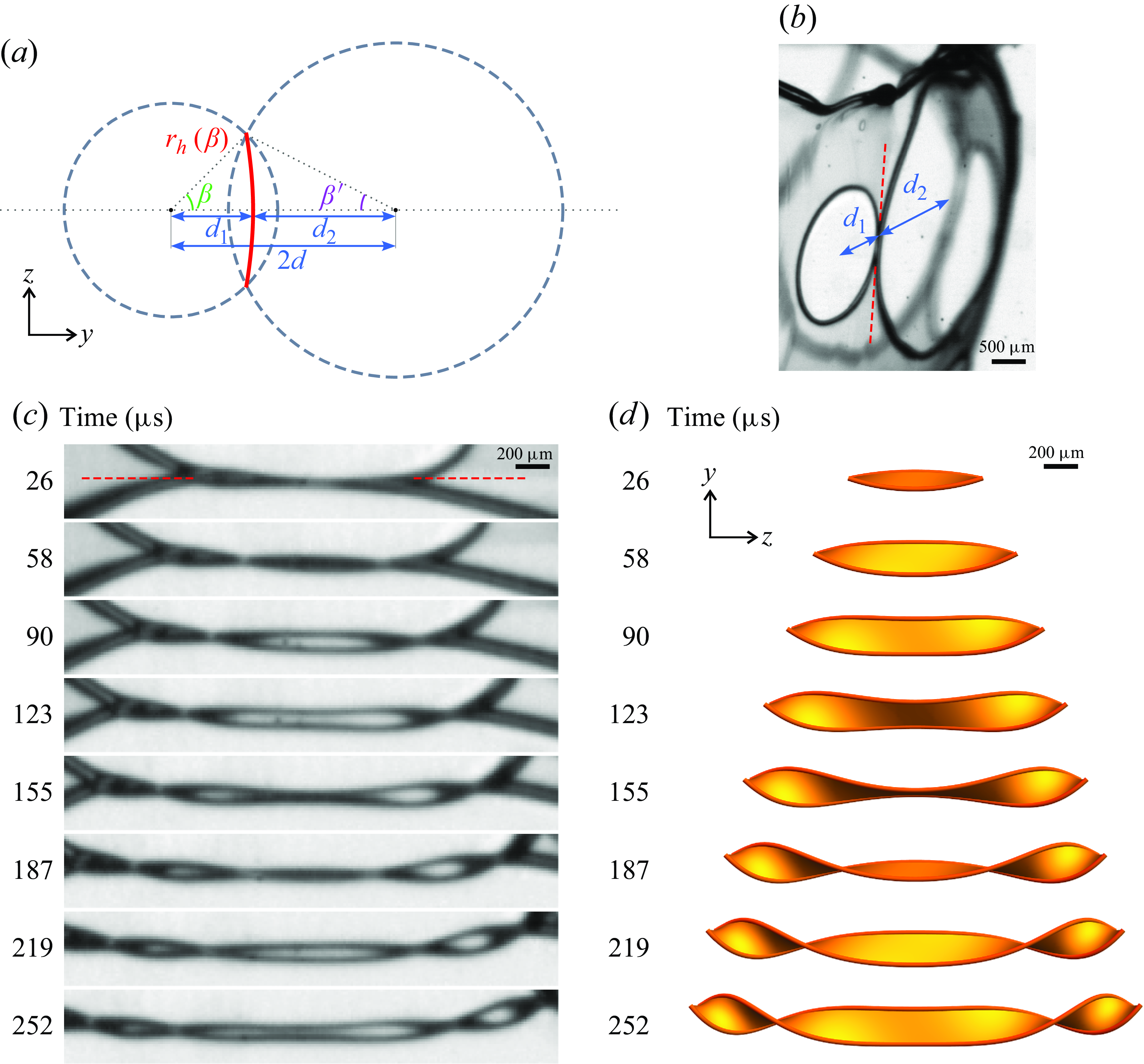
is measured from the centre of the hole. The rotation axis is denoted by the red dashed line. (c, d) Magnified video frames of the spinning twisted ribbon and the corresponding calculated surfaces, showing the region of interest along the rotation axis (red dashed line in (b)). The surfaces are plotted by the model (3.2), using the measured parameters
$\beta$
is measured from the centre of the hole. The rotation axis is denoted by the red dashed line. (c, d) Magnified video frames of the spinning twisted ribbon and the corresponding calculated surfaces, showing the region of interest along the rotation axis (red dashed line in (b)). The surfaces are plotted by the model (3.2), using the measured parameters $u_c$
= 2.69 m s−1,
$u_c$
= 2.69 m s−1, $d$
= 1.08 mm,
$d$
= 1.08 mm, $\omega _0=32\,500$
s
$\omega _0=32\,500$
s $^{-1}$
or 5170 Hz. No fitting parameters are involved. See also supplementary movie 6. (e) Rotated view of the last plotted ribbon surface in (d).
$^{-1}$
or 5170 Hz. No fitting parameters are involved. See also supplementary movie 6. (e) Rotated view of the last plotted ribbon surface in (d).
3. Spinning twisted ribbons
3.1. Phenomenology
To describe how spinning twisted ribbons are formed, we begin by considering a curved liquid sheet that has developed two holes, as illustrated in figure 2(a). It is well known that the holes expand at a constant speed, known as the Taylor–Culick velocity, given by $u_c=\sqrt{2\gamma / (\rho \delta) }$
, where
$u_c=\sqrt{2\gamma / (\rho \delta) }$
, where $\gamma$
is the surface tension,
$\gamma$
is the surface tension, $\rho$
is the density of the liquid, and
$\rho$
is the density of the liquid, and $\delta$
is the thickness of the sheet. Because the radius of curvature of the crown film,
$\delta$
is the thickness of the sheet. Because the radius of curvature of the crown film, $R_f$
, is much larger than the travelled distance of the rim,
$R_f$
, is much larger than the travelled distance of the rim, $d$
, it has negligible impact on the measured Taylor–Culick velocity
$d$
, it has negligible impact on the measured Taylor–Culick velocity $u_c$
. Specifically, in our experiments,
$u_c$
. Specifically, in our experiments, $d/R_f\lt 0.1$
, so that the projection factor
$d/R_f\lt 0.1$
, so that the projection factor $\cos \theta _p \approx 1-((d/R_f)^2/2) \approx 1$
, where
$\cos \theta _p \approx 1-((d/R_f)^2/2) \approx 1$
, where $\theta _p$
is the angle between the image plane and the tangential plane at the hole. As a hole expands, the displaced fluid accumulates at the circular rim of the liquid sheet, while the thickness of the rest of the sheet remains constant (Savva & Bush Reference Savva and Bush2009).
$\theta _p$
is the angle between the image plane and the tangential plane at the hole. As a hole expands, the displaced fluid accumulates at the circular rim of the liquid sheet, while the thickness of the rest of the sheet remains constant (Savva & Bush Reference Savva and Bush2009).
As the two holes expand, their edges will eventually ‘meet’, while the subsequent development depends on whether the liquid sheet is planar or curved. On a planar liquid sheet, it has been shown that the rims will collide head-on, producing lamella and ejecta when the collision Weber number is sufficiently high (Néel et al. Reference Néel, Lhuissier and Villermaux2020; Tang et al. Reference Tang, Adcock and Mostert2024). On a curved liquid sheet, in contrast, the rims cross each other laterally, as demonstrated in supplementary movie 2 and figure 2(a,b). This occurs because the trajectories of the rims deviate from the initial curved surface: since surface tension acts tangentially, initially, there is no centripetal force to maintain the rims on a curved path, as illustrated in figure 2(a) and supplementary movie 5. Note that at later times, as the rims deviate from the initial surface, the liquid film bends outwards, and surface tension provides centripetal acceleration for curvilinear motions. In the case of a single-hole rupture on a bubble, it has been observed that the centripetal acceleration destabilises the rim via Rayleigh–Taylor instability (Lhuissier & Villermaux Reference Lhuissier and Villermaux2012; Jiang et al. Reference Jiang, Rotily, Villermaux and Wang2022). However, in the current case of multiple-hole ruptures, the rims meet one another ( $\sim$
0.3 ms) before the instability becomes prominent (
$\sim$
0.3 ms) before the instability becomes prominent ( $\sim$
50 ms) (figure 19 of Lhuissier & Villermaux Reference Lhuissier and Villermaux2012).
$\sim$
50 ms) (figure 19 of Lhuissier & Villermaux Reference Lhuissier and Villermaux2012).
The spinning twisted ribbon is formed after the rims cross laterally. Due to the attractive surface tension of the connecting liquid sheet, the rims rotate around the axis where they cross laterally, indicated by the dashed red line in figure 2(b,c), forming the spinning twisted ribbon, as shown in supplementary movie 2 and figure 2(c). We define $t = 0$
as the moment that the rims cross laterally for the first time.
$t = 0$
as the moment that the rims cross laterally for the first time.
Note that not every pair of neighbouring holes produces a twisted ribbon. We find that the average number of ribbons per hole is $0.8 \pm 0.1$
, based on a total count of 198 holes across 21 drop-impact experiments. Qualitatively, even on a curved film, head-on collisions between rims can occur in the following scenarios, preventing the ribbon formation. First, when the two holes are very close to each other, the effect of curvature is insignificant. Second, the two holes rupture simultaneously, resulting in a mirror symmetric system. This symmetry leads to an angled head-on collision.
$0.8 \pm 0.1$
, based on a total count of 198 holes across 21 drop-impact experiments. Qualitatively, even on a curved film, head-on collisions between rims can occur in the following scenarios, preventing the ribbon formation. First, when the two holes are very close to each other, the effect of curvature is insignificant. Second, the two holes rupture simultaneously, resulting in a mirror symmetric system. This symmetry leads to an angled head-on collision.
We identify several key features of the twisted ribbon from the video images. The ribbon looks similar to a helicoid, but strictly speaking it is not. The ribbon exhibits mirror symmetry with respect to the central point. There are several points of conjunction (red arrows in figure 2 c), where the two rims align along the same line of sight, visually overlapping but not physically touching. The number of conjunction points increases over time, indicating more twisting of the sheet, with the points moving outwards along the axis.
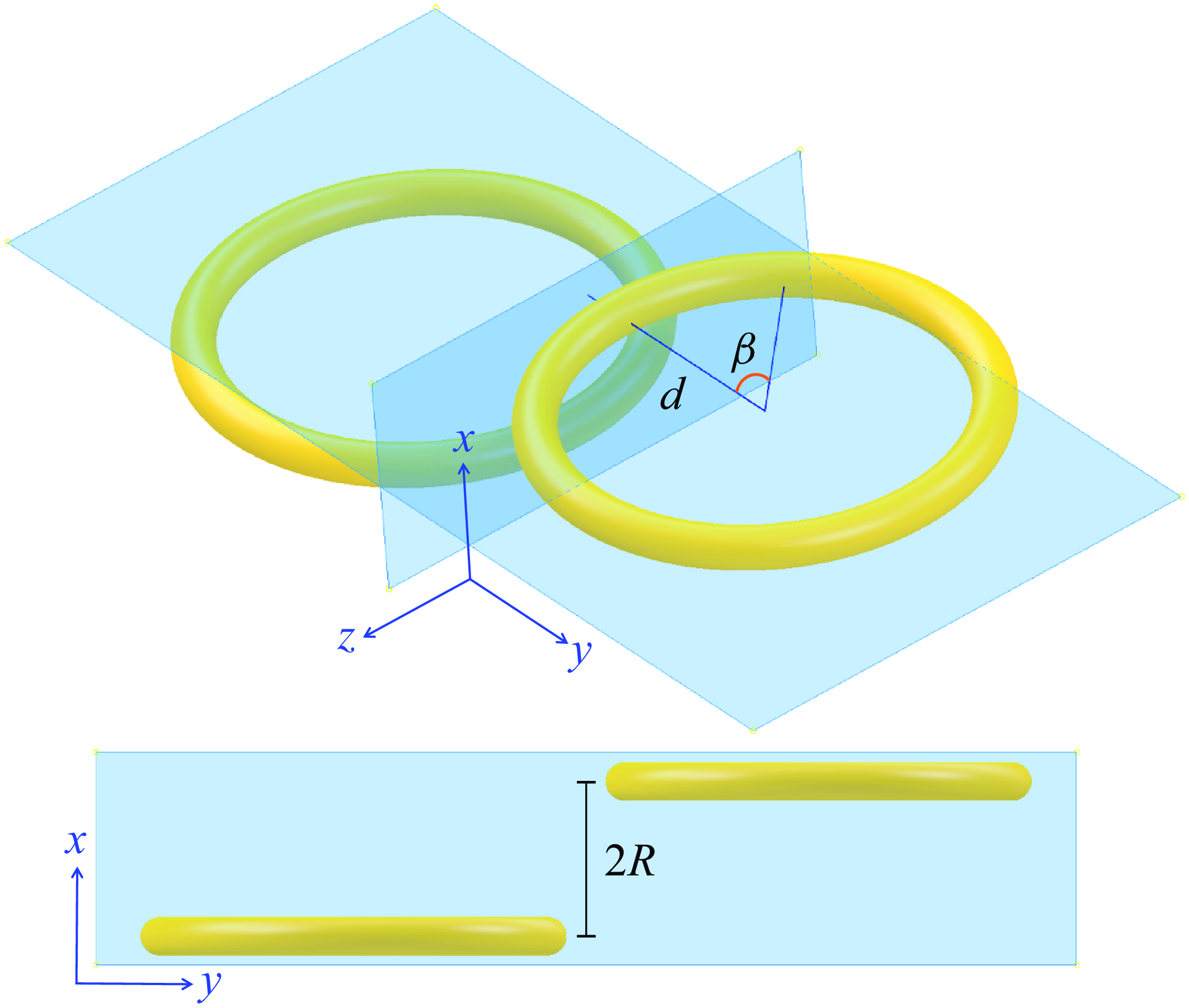
Schematic drawings for the derivation of (3.2).
3.2. Kinematic model
To explain the key features of the spinning twisted ribbon, we propose a kinematic model with several idealised assumptions. The predicted structures from the model are shown in figure 2(d) and supplementary movie 6, and compared with the data in figure 2(c). The parameters involved are defined in figure 2(a,b) and elaborated by the schematic drawings in figure 3.
In this kinematic model, we consider two horizontal circular holes of equal size. Let the origin of our coordinate system be the midpoint between the rupture points (centres) of the two holes. The rims of the holes expand horizontally at speed $u_{c}$
from their rupture points along two planes parallel to the
$u_{c}$
from their rupture points along two planes parallel to the $yz$
-plane and separated by a distance
$yz$
-plane and separated by a distance $2R$
. The distance between the
$2R$
. The distance between the $xz$
-plane and rupture points is
$xz$
-plane and rupture points is $d$
. At time
$d$
. At time $t=0$
, the rims reach the
$t=0$
, the rims reach the $xz$
-plane and conjunct (relative to an observer at
$xz$
-plane and conjunct (relative to an observer at $x\rightarrow \infty )$
for the first time. Thus we call the
$x\rightarrow \infty )$
for the first time. Thus we call the $xz$
-plane the conjunction plane.
$xz$
-plane the conjunction plane.
Next, we consider an arbitrary segment of the rim, represented by an azimuthal angle $\beta$
, as shown in figure 3. It reaches the conjunction plane at time
$\beta$
, as shown in figure 3. It reaches the conjunction plane at time $\tau = d/(u_c \cos \beta )- d/u_c$
and at
$\tau = d/(u_c \cos \beta )- d/u_c$
and at $z$
-position
$z$
-position $z_0=d \tan \beta =(u_c\tau +d)\sin \beta$
. After reaching the conjunction plane, it rotates around a rotation axis (
$z_0=d \tan \beta =(u_c\tau +d)\sin \beta$
. After reaching the conjunction plane, it rotates around a rotation axis ( $z$
-axis) with rotation radius
$z$
-axis) with rotation radius $R$
, angular speed
$R$
, angular speed $\omega = u_c \cos \beta /R$
and axial speed
$\omega = u_c \cos \beta /R$
and axial speed $u_z= u_c \sin \beta$
. For simplicity, here we take the rotation radius
$u_z= u_c \sin \beta$
. For simplicity, here we take the rotation radius $R$
as a constant, implying a circular closed orbit. The actual non-circular open orbit is presented later with the central force model. Therefore, the motion of a segment of the rim is described by
$R$
as a constant, implying a circular closed orbit. The actual non-circular open orbit is presented later with the central force model. Therefore, the motion of a segment of the rim is described by
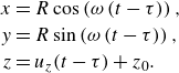 \begin{align} x &= R \cos \left (\omega \left ( t-\tau \right )\right ),\nonumber\\ y &= R \sin \left (\omega \left ( t-\tau \right )\right ),\nonumber\\ z &= u_z(t-\tau ) +z_0. \end{align}
Recall that $\omega ,\tau ,u_z,z_0$
can be expressed in terms of the variable
$\omega ,\tau ,u_z,z_0$
can be expressed in terms of the variable $\beta$
and constants
$\beta$
and constants $u_c,R,d$
.
$u_c,R,d$
.
Finally, we assume that the ribbon surface is a ruled surface formed by connecting two rims by introducing a parameter $\alpha$
, and each rim is a collection of rim segments described by (3.1) with parameter
$\alpha$
, and each rim is a collection of rim segments described by (3.1) with parameter $\beta$
and constants
$\beta$
and constants $u_c,R,d$
. The surface of the twisted ribbon is described by the parametric equations
$u_c,R,d$
. The surface of the twisted ribbon is described by the parametric equations
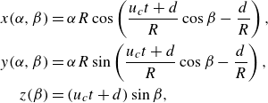 \begin{align} x(\alpha ,\beta )&=\alpha R \cos \left ( \frac {u_c t+d}{R}\cos \beta - \frac {d}{R} \right ),\nonumber\\ y(\alpha , \beta )&=\alpha R \sin \left ( \frac {u_c t+d}{R}\cos \beta - \frac {d}{R} \right ),\nonumber\\ z(\beta )&=(u_c t+d)\sin \beta, \end{align}
where $-1 \leqslant \alpha \leqslant 1$
,
$-1 \leqslant \alpha \leqslant 1$
, $-\beta _0 \leqslant \beta \leqslant \beta _0$
. Here the range of
$-\beta _0 \leqslant \beta \leqslant \beta _0$
. Here the range of $\beta$
is bounded by
$\beta$
is bounded by $\beta _0$
that satisfy
$\beta _0$
that satisfy $t\geqslant \tau$
in (3.1), given by
$t\geqslant \tau$
in (3.1), given by $\cos \beta _0= d/(u_c t+d)$
.
$\cos \beta _0= d/(u_c t+d)$
.
This surface is plotted in figure 2(d) using measured parameters $u_c$
= 2.69 m s−1,
$u_c$
= 2.69 m s−1, $d$
= 1.08 mm and
$d$
= 1.08 mm and $R=82.8$ $\unicode{x03BC}$
m, obtained from the video frames in figure 2(c). The velocity
$\unicode{x03BC}$
m, obtained from the video frames in figure 2(c). The velocity $u_c$
and distance
$u_c$
and distance $d$
are measured with correction for parallax error, as described in Appendix B. The radius
$d$
are measured with correction for parallax error, as described in Appendix B. The radius $R$
is obtained by measuring the central angular frequency
$R$
is obtained by measuring the central angular frequency $\omega _0\equiv u_c/R=32\,500$
s
$\omega _0\equiv u_c/R=32\,500$
s $^{-1}$
or 5170 Hz. The calculated surfaces resemble the ribbons observed in the experiment, reproducing the key features discussed earlier. No fitting parameters are involved. Note that the rims’ surfaces are not included in the equations, and only added in figure 2(d,e) for the sake of clarity. The model only considers two holes, while in the experiments more than two holes frequently occur, affecting the shape of the twisted ribbon. For example, see the third rim on the right-hand side in figure 2(c).
$^{-1}$
or 5170 Hz. The calculated surfaces resemble the ribbons observed in the experiment, reproducing the key features discussed earlier. No fitting parameters are involved. Note that the rims’ surfaces are not included in the equations, and only added in figure 2(d,e) for the sake of clarity. The model only considers two holes, while in the experiments more than two holes frequently occur, affecting the shape of the twisted ribbon. For example, see the third rim on the right-hand side in figure 2(c).
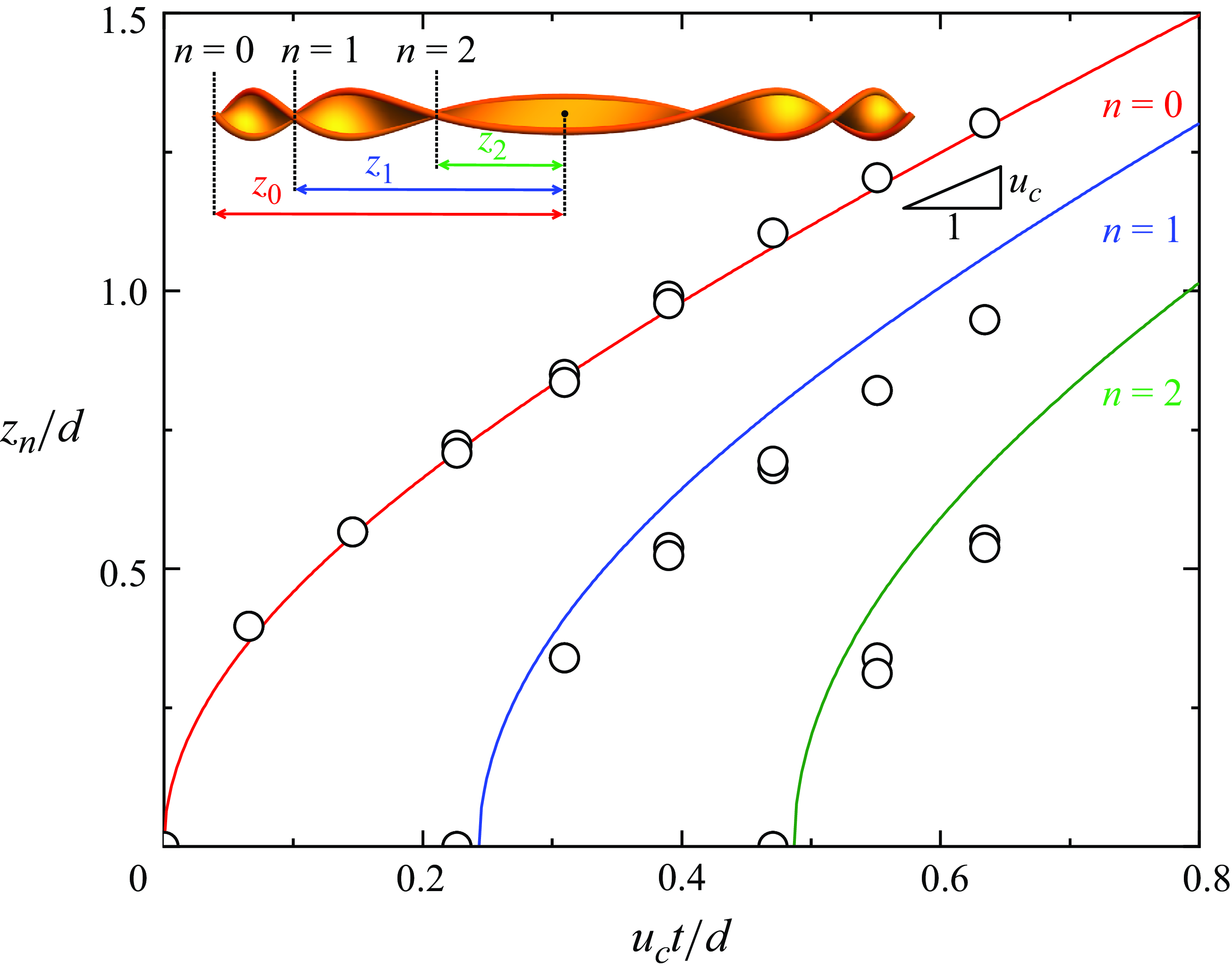
Furthermore, to verify the kinematic model, we compare the positions of the measured and calculated conjunction points at different times in figure 4. By (3.1) and (3.2), the $z$
-position of conjunction points are given by
$z$
-position of conjunction points are given by $z_n=(u_c t+d)\sin \beta _n$
, where the angles
$z_n=(u_c t+d)\sin \beta _n$
, where the angles $\beta _n$
have to satisfy the condition
$\beta _n$
have to satisfy the condition $\omega (t-\tau )=n\pi$
with
$\omega (t-\tau )=n\pi$
with $n=0,1,2,\dots$
. Simplifying, the
$n=0,1,2,\dots$
. Simplifying, the $z$
-positions of conjunction points are
$z$
-positions of conjunction points are
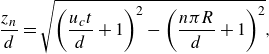 \begin{equation} \frac {z_n}{d}=\sqrt {\left (\frac {u_c t}{d}+1\right )^2-\left (\frac {n \pi R}{d}+1\right )^2}, \end{equation}
for $t \geqslant n\pi R/u_c$
and
$t \geqslant n\pi R/u_c$
and $n=0,1,2,\dots$
. They are plotted in figure 4 using the same values of
$n=0,1,2,\dots$
. They are plotted in figure 4 using the same values of $d$
and
$d$
and $R$
employed in plotting figure 2(d). The measured data and calculated results show reasonably good agreement.
$R$
employed in plotting figure 2(d). The measured data and calculated results show reasonably good agreement.
New conjunction points emerge at regular time intervals of $\pi R/u_c$
. By (3.3), the speeds of conjunction points are
$\pi R/u_c$
. By (3.3), the speeds of conjunction points are
 \begin{equation} \frac {1}{u_c}\frac {\mathrm{d}z_n}{\mathrm{d}t} \approx 1+\frac {1}{2}\left (\frac {n\pi R/d+1}{u_c t/d+1}\right )^2+\cdots . \end{equation}
At large time, their speed approaches a constant value $u_c$
, which is the Taylor–Culick speed in our case.
$u_c$
, which is the Taylor–Culick speed in our case.
Positions of conjunction points at different times. The measured data (dots) agree well with the calculation results (curved lines) predicted by the kinematic model and (3.3). Some data points overlap due to the mirror symmetry with respect to the $xy$
-plane.
$xy$
-plane.
Next, we calculate the mean curvature of the ribbon by
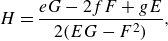 \begin{equation} H=\frac {eG-2fF+gE}{2(EG-F^{2})} , \end{equation}
where $H$
is the mean curvature,
$H$
is the mean curvature, $\{E, F, G\}$
and
$\{E, F, G\}$
and $\{e, f, g\}$
are the coefficients of the first and second fundamental form of the surface described by (3.2). We get
$\{e, f, g\}$
are the coefficients of the first and second fundamental form of the surface described by (3.2). We get
 \begin{equation} H(\alpha ,\beta )=\left (\frac {1}{u_{c}t+d}\right )\left ( \frac {\alpha }{2\left (\cos ^{2}\beta + \alpha ^2\sin ^{2}\beta \right )^{3/2}}\right ) . \end{equation}
Numerically, in the range of interest $|\beta |\lt \pi /4$
and
$|\beta |\lt \pi /4$
and $|\alpha |\leqslant 1$
,
$|\alpha |\leqslant 1$
,
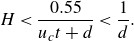 \begin{equation} H\lt \frac {0.55}{u_c t+d}\lt \frac {1}{d} . \end{equation}
This means the upper bound is $1/d$
. Typically, the hole–axis distance
$1/d$
. Typically, the hole–axis distance $d$
(
$d$
( $\sim$
1 mm) is much larger than the rotation radius
$\sim$
1 mm) is much larger than the rotation radius $R$
(
$R$
( $\sim$
0.1 mm), which represents the size of the ribbon. Therefore, the calculated mean curvature of the ribbon is small.
$\sim$
0.1 mm), which represents the size of the ribbon. Therefore, the calculated mean curvature of the ribbon is small.
The small mean curvature obtained agrees with our expectations. First, physically, it suggests a pressure equilibrium across the film, which is known to be established rapidly after film rupture (Bird et al. Reference Bird, De Ruiter, Courbin and Stone2010). Second, geometrically, it aligns with the visual similarity between the twisted ribbon and the helicoid, which is a minimal surface.
3.3. Asymmetric kinematic model
We extend the kinematic model to account for asymmetric cases where the sizes of the two holes are different. This scenario happens when a larger hole, which is formed earlier, interacts with a smaller hole. When the holes are the same size, it is obvious that their rims meet along a straight line at the midpoint. When the hole sizes are different, their rims meet along a hyperbola, as illustrated in figure 5. This is because the difference in radius between the two expanding holes is a constant. This is analogous to the interference of two circular waves (Pain Reference Pain2005, p. 356). The hyperbola is described by the equation in polar coordinate as
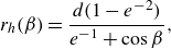 \begin{equation} r_{h} (\beta ) = \frac {d(1 - e^{-2})}{e^{-1} + \cos \beta } , \end{equation}
where $e= ({d_1+d_2})/({d_2-d_1})$
is the eccentricity,
$e= ({d_1+d_2})/({d_2-d_1})$
is the eccentricity, $2d=d_1+d_2$
is the distance between the centres of the two holes,
$2d=d_1+d_2$
is the distance between the centres of the two holes, $d_{1,2}$
are the shortest distances from the centres of the holes to the ribbon and
$d_{1,2}$
are the shortest distances from the centres of the holes to the ribbon and $d_1\lt d_2$
, as defined in figure 5(a). If the system is symmetric,
$d_1\lt d_2$
, as defined in figure 5(a). If the system is symmetric, $e^{-1}=0$
and thus
$e^{-1}=0$
and thus $r_h=d/\cos \beta$
becomes a straight line as expected.
$r_h=d/\cos \beta$
becomes a straight line as expected.
The asymmetric model. (a) Schematic diagram consisting of two holes of different sizes (dotted circles), with their rims meeting along a hyperbola (red) and forming a ribbon. (b) Snapshot of a small hole (left) interacting with a large hole (right). (c,d) Magnified video frames and the corresponding predicted surfaces of the spinning twisted ribbon formed by a small hole (top) and a large hole (bottom). The surfaces are plotted by (3.14), using the measured parameters $u_c$
= 2.17 m s−1,
$u_c$
= 2.17 m s−1, $d_1$
= 1.19 mm,
$d_1$
= 1.19 mm, $d_2$
= 1.92 mm,
$d_2$
= 1.92 mm, $\omega _0=19\,500$
s
$\omega _0=19\,500$
s $^{-1}$
or 3100 Hz.
$^{-1}$
or 3100 Hz.
In the asymmetric case, the momenta of the two rims are also different. The rim of the larger hole is thicker due to the larger hole size and volume conservation, as the rim collects the film liquid during its motion. Its normal component of the velocity is also larger because $\beta ' \lt \beta$
, as shown in figure 5(a). Therefore, the rim of the larger hole should have a larger momentum than that of the smaller hole, driving the ribbons to drift in one direction. Nevertheless, in our experiments, the liquid sheet itself is also moving, making it difficult to measure this momentum mismatch directly.
$\beta ' \lt \beta$
, as shown in figure 5(a). Therefore, the rim of the larger hole should have a larger momentum than that of the smaller hole, driving the ribbons to drift in one direction. Nevertheless, in our experiments, the liquid sheet itself is also moving, making it difficult to measure this momentum mismatch directly.
We now express the ribbon surface for the asymmetric case in a form similar to the symmetric case given in (3.2). For simplicity, we assume that their rim thicknesses are the same, so that
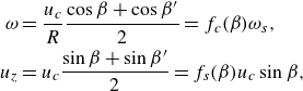 \begin{align} \omega &= \frac {u_c}{R}\frac {\cos \beta + \cos \beta '}{2} =f_c(\beta ) \omega _s,\nonumber\\ u_z &= u_c\frac {\sin \beta + \sin \beta '}{2} =f_s(\beta ) u_c \sin \beta , \end{align}
where $\omega _s= u_c \cos \beta /R$
is the angular speed for the symmetric case,
$\omega _s= u_c \cos \beta /R$
is the angular speed for the symmetric case, $f_c(\beta )$
and
$f_c(\beta )$
and $f_s(\beta )$
are geometric factors that account for the asymmetry, given by
$f_s(\beta )$
are geometric factors that account for the asymmetry, given by
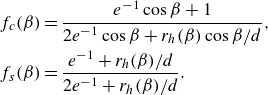 \begin{align} f_c(\beta ) &= \frac {e^{-1}\cos \beta +1}{2e^{-1}\cos \beta +r_h(\beta )\cos \beta /d},\nonumber\\ f_s(\beta ) &= \frac {e^{-1}+r_h(\beta )/d}{2e^{-1}+r_h(\beta )/d}. \end{align}
If the configuration is symmetric ( $e^{-1}=0$
),
$e^{-1}=0$
), $f_c(\beta )=f_s(\beta )=1$
as expected. The phase lag
$f_c(\beta )=f_s(\beta )=1$
as expected. The phase lag $\tau$
for the asymmetric case is
$\tau$
for the asymmetric case is
 \begin{align} \tau &= \frac {r_h (\beta )}{u_c}-\frac {r_h (0)}{u_c} =g(\beta ) \tau _s , \end{align}
where $\tau _s= d/(u_c \cos \beta )- d/u_c$
is the phase lag of the symmetric case, the geometric factor
$\tau _s= d/(u_c \cos \beta )- d/u_c$
is the phase lag of the symmetric case, the geometric factor $g(\beta )$
is given by
$g(\beta )$
is given by
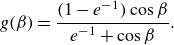 \begin{align} g(\beta ) &= \frac {(1-e^{-1})\cos \beta }{e^{-1}+\cos \beta }. \end{align}
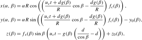
Therefore, similar to (3.2), the parametric equations are
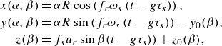 \begin{align} x(\alpha ,\beta )&=\alpha R \cos \left (f_c \omega _s \left ( t-g\tau _s \right ) \right ),\nonumber\\ y(\alpha , \beta )&=\alpha R \sin \left (f_c \omega _s \left ( t-g\tau _s \right ) \right )-y_0(\beta ),\nonumber\\ z(\beta )&= f_s u_c \sin \beta (t-g\tau _s))+z_0(\beta ), \end{align}
or, equivalently,
 \begin{align} x(\alpha ,\beta )&=\alpha R \cos \left ( \left ( \frac {u_c t+d g(\beta )}{R}\cos \beta - \frac {d g(\beta )}{R} \right ) f_c(\beta ) \right ),\nonumber\\ y(\alpha , \beta )&=\alpha R \sin \left ( \left ( \frac {u_c t+d g(\beta )}{R}\cos \beta - \frac {d g(\beta )}{R} \right ) f_c(\beta ) \right )-y_0(\beta ),\nonumber\\ z(\beta )&= f_s(\beta ) \sin \beta \left (u_c t - g(\beta ) \left (\frac {d}{\cos \beta }-d\right )\right )+z_0(\beta ), \end{align}
where $y_0(\beta )=r_{h}(\beta ) \cos \beta -r_{h}(0)$
and
$y_0(\beta )=r_{h}(\beta ) \cos \beta -r_{h}(0)$
and $z_0(\beta )=r_{h} (\beta ) \sin \beta$
. An example involving two holes of different sizes is shown in figure 5(b,c). The predicted ribbon surface is plotted in figure 5(d) using measured parameters
$z_0(\beta )=r_{h} (\beta ) \sin \beta$
. An example involving two holes of different sizes is shown in figure 5(b,c). The predicted ribbon surface is plotted in figure 5(d) using measured parameters $u_c$
= 2.17 m s−1,
$u_c$
= 2.17 m s−1, $d_1$
= 1.19 mm,
$d_1$
= 1.19 mm, $d_2$
= 1.92 mm and
$d_2$
= 1.92 mm and $R=111$ $\unicode{x03BC}$
m. From
$\unicode{x03BC}$
m. From $d_1$
and
$d_1$
and $d_2$
, we get
$d_2$
, we get $d$
= 1.55 mm and eccentricity
$d$
= 1.55 mm and eccentricity $e$
= 4.24. The calculated surfaces resemble the ribbons observed in the experiment.
$e$
= 4.24. The calculated surfaces resemble the ribbons observed in the experiment.
In this case, $d_2/d_1=1.62$
. For comparison, the earlier case presented in figure 2 has
$d_2/d_1=1.62$
. For comparison, the earlier case presented in figure 2 has $d_2/d_1=1.07$
, and its slight asymmetry can therefore be neglected.
$d_2/d_1=1.07$
, and its slight asymmetry can therefore be neglected.
3.4. Dynamics: two-body central force model
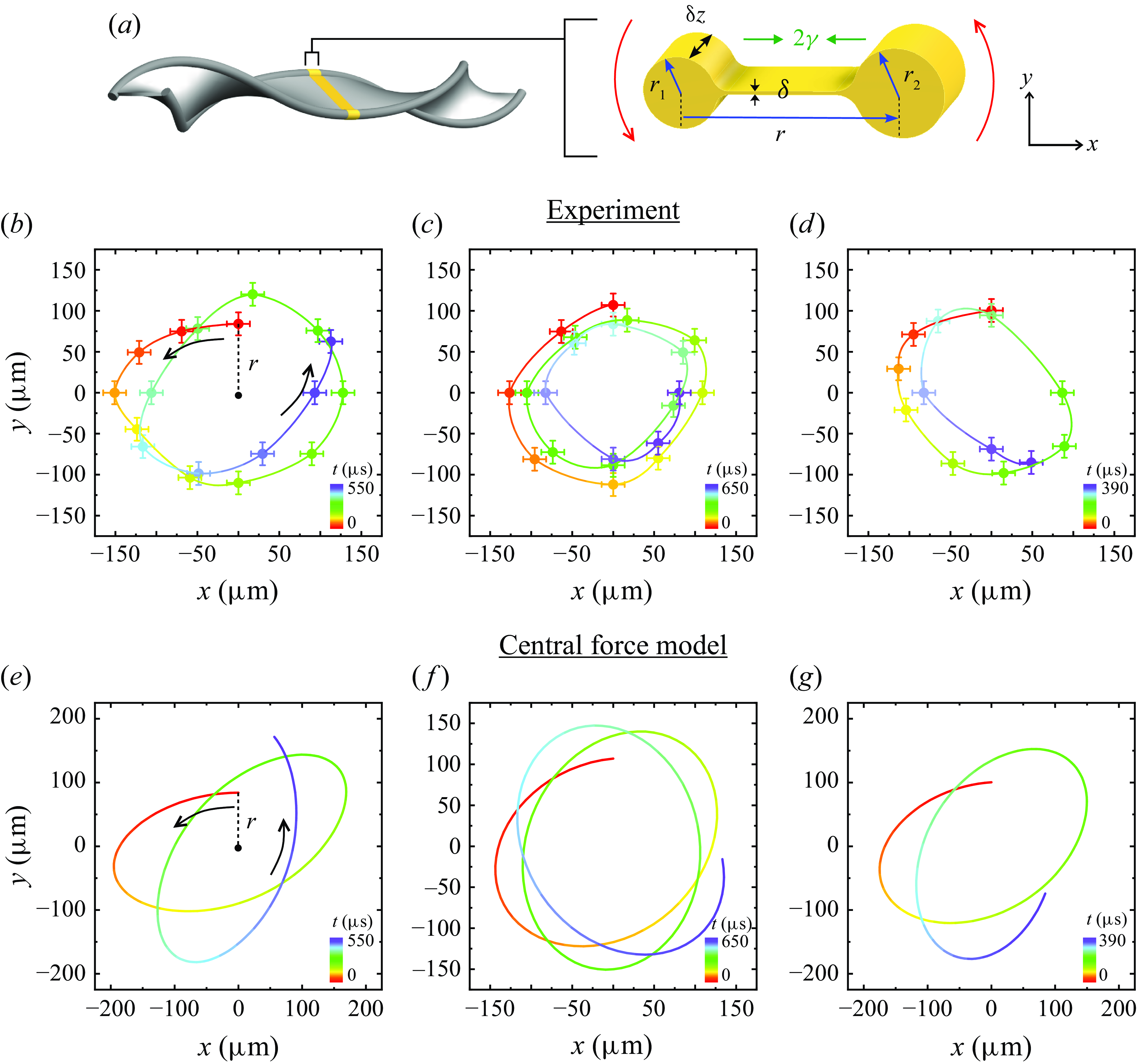
We elucidate the ‘orbit’ of the rims of the spinning ribbon by using the classical two-body central force model and direct measurements (Goldstein, Poole & Safko Reference Goldstein, Poole and Safko2001). We assumed a circular orbit in the last section, but in fact it is open and non-circular. Consider a thin strip of the ribbon with a dumbbell-shaped cross-section, as shown in figure 6(a), where two circular rims are connected by a thin liquid string. The surface tension on the liquid string exerts an attractive central force between the two circular rims. For simplicity, we consider a thin strip at the centre plane ( $z=0$
).
$z=0$
).
Explanation of the ribbon’s orbit by the two-body central force model. (a) Sketch of a thin strip of the ribbon with a dumbbell-shaped cross-section. Two circular rims are connected by a thin liquid string, which exerts an attractive central force. (b–d) Measured orbits, showing the data (dots) and interpolation (line). The colours indicate time progression, ranging from red ( $t=0$
) to purple (
$t=0$
) to purple ( $t=550$
, 650 and 390
$t=550$
, 650 and 390 $\unicode{x03BC}$
s). (e–g) The corresponding orbits calculated by solving (3.15) with liquid properties
$\unicode{x03BC}$
s). (e–g) The corresponding orbits calculated by solving (3.15) with liquid properties $\gamma = 20.8$
mN m−1,
$\gamma = 20.8$
mN m−1, $\rho = 960$
kg m−
$\rho = 960$
kg m− $^3$
, and initial conditions approximated from measurements: (e)
$^3$
, and initial conditions approximated from measurements: (e) $r(0)= 841$ $\unicode{x03BC}$
m,
$\unicode{x03BC}$
m, $v_{\theta }(0)=4.45$
m s−1,
$v_{\theta }(0)=4.45$
m s−1, $v_{r}(0)= 0$
,
$v_{r}(0)= 0$
, $m_{\mu }= 586$ $\unicode{x03BC}$
g m−1; (f)
$\unicode{x03BC}$
g m−1; (f) $r(0)= 1071$ $\unicode{x03BC}$
m,
$\unicode{x03BC}$
m, $v_{\theta }(0)= 4.01$
m s−1,
$v_{\theta }(0)= 4.01$
m s−1, $v_{r}(0)=$ $-0.40$
m s−1,
$-0.40$
m s−1, $m_{\mu } = 449$ $\unicode{x03BC}$
g m−1; (g)
$\unicode{x03BC}$
g m−1; (g) $r(0) = 1003$ $\unicode{x03BC}$
m,
$\unicode{x03BC}$
m, $v_{\theta }(0) = 4.94$
m s−1,
$v_{\theta }(0) = 4.94$
m s−1, $v_{r}(0)=$ $-0.33$
m s−1,
$-0.33$
m s−1, $m_{\mu } = 397$ $\unicode{x03BC}$
g m−1. The data agree with the model semi-quantitatively.
$\unicode{x03BC}$
g m−1. The data agree with the model semi-quantitatively.
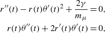
Following the classical treatment, the two-body system is reduced to a one-body system with a relative position $\textbf {r}(t)$
and a reduced mass per length
$\textbf {r}(t)$
and a reduced mass per length $m_{\mu }=\rho \pi r_{1}^2 r_{2}^2/(r_{1}^2+r_{2}^2)$
, where
$m_{\mu }=\rho \pi r_{1}^2 r_{2}^2/(r_{1}^2+r_{2}^2)$
, where $\rho$
is the density of the liquid sheet,
$\rho$
is the density of the liquid sheet, $r_{1,2}$
are the radii of the rims. The magnitude of the central force per length is twice the surface tension
$r_{1,2}$
are the radii of the rims. The magnitude of the central force per length is twice the surface tension $\gamma$
, accounting for both the upper and lower surfaces of the liquid string. The orbit is obtained by solving the following differential equations numerically by Mathematica (Taborek Reference Taborek2010),
$\gamma$
, accounting for both the upper and lower surfaces of the liquid string. The orbit is obtained by solving the following differential equations numerically by Mathematica (Taborek Reference Taborek2010),
 \begin{align} r''(t)-r(t)\theta '(t)^2+\frac {2 \gamma }{m_{\mu} }=0, \nonumber\\ r(t)\theta ''(t)+2 r'(t)\theta '(t)=0, \end{align}
where $r(t)$
and
$r(t)$
and $\theta (t)$
are the relative distance and angle at time
$\theta (t)$
are the relative distance and angle at time $t$
in the polar coordinate system. The initial conditions,
$t$
in the polar coordinate system. The initial conditions, $v_r(t)\equiv r'(t)$
and
$v_r(t)\equiv r'(t)$
and $v_\theta (t)\equiv r(t)\theta '(t)$
, are measured from experiments. The value of
$v_\theta (t)\equiv r(t)\theta '(t)$
, are measured from experiments. The value of $v_\theta (0)$
is the measured Taylor–Culick speed, i.e. the constant film retraction speed before spinning. Open non-circular orbits are obtained as expected, according to Bertrand’s theorem.
$v_\theta (0)$
is the measured Taylor–Culick speed, i.e. the constant film retraction speed before spinning. Open non-circular orbits are obtained as expected, according to Bertrand’s theorem.
We experimentally measure the orbits using two high-speed cameras positioned at orthogonal angles, and then compare them with the theoretical orbits. The measured orbits are shown in figure 6(b–d). The dots with error bars represent measured data, and the line shows an interpolated orbit. The colours indicate time progression, ranging from red ( $t=0$
) to purple (
$t=0$
) to purple ( $t=550$
, 650 and 390
$t=550$
, 650 and 390 $\unicode{x03BC}$
s). We calculate the orbits, as shown in figure 6(e–g), by solving (3.15) numerically with real liquid properties and measured initial conditions (see figure captions). The experiments agree with numerical calculations semiquantitatively, revealing similar non-circular open orbits.
$\unicode{x03BC}$
s). We calculate the orbits, as shown in figure 6(e–g), by solving (3.15) numerically with real liquid properties and measured initial conditions (see figure captions). The experiments agree with numerical calculations semiquantitatively, revealing similar non-circular open orbits.
We compare the measured and predicted orbits by their periods, as shown in figure 7(a). Although bounded open orbits cannot be characterised by rotation period, they can instead be characterised by the angular period $T_\theta$
and the radial period
$T_\theta$
and the radial period $T_r$
. We calculate the angular period by
$T_r$
. We calculate the angular period by $T_\theta =\Delta t_\theta 2\pi / \Delta \theta$
, where
$T_\theta =\Delta t_\theta 2\pi / \Delta \theta$
, where $\Delta \theta$
is the angular distance travelled during a time interval
$\Delta \theta$
is the angular distance travelled during a time interval $\Delta t_\theta$
. The radial period is calculated by
$\Delta t_\theta$
. The radial period is calculated by $T_r=\Delta t_r/N_{cc}$
, where
$T_r=\Delta t_r/N_{cc}$
, where $N_{cc}$
is the number of crest-to-crest cycles observed in the plot of
$N_{cc}$
is the number of crest-to-crest cycles observed in the plot of $r(t)$
over a time interval
$r(t)$
over a time interval $\Delta t_r$
(Arya Reference Arya1997, p. 258). The measured and predicted periods of three different experiments are shown in figure 7(a), which shows reasonably good agreement.
$\Delta t_r$
(Arya Reference Arya1997, p. 258). The measured and predicted periods of three different experiments are shown in figure 7(a), which shows reasonably good agreement.
Comparison of the periods and radii between the central force model and the experimental results. (a) The angular period (red) and radial period (blue) from three different experiments are shown. The measured periods agree with the predicted periods. (b) The plots of $r(t)$
of the orbits in figures 6(b) and 6(e) are shown. The measured orbit is shrinking over time.
$r(t)$
of the orbits in figures 6(b) and 6(e) are shown. The measured orbit is shrinking over time.
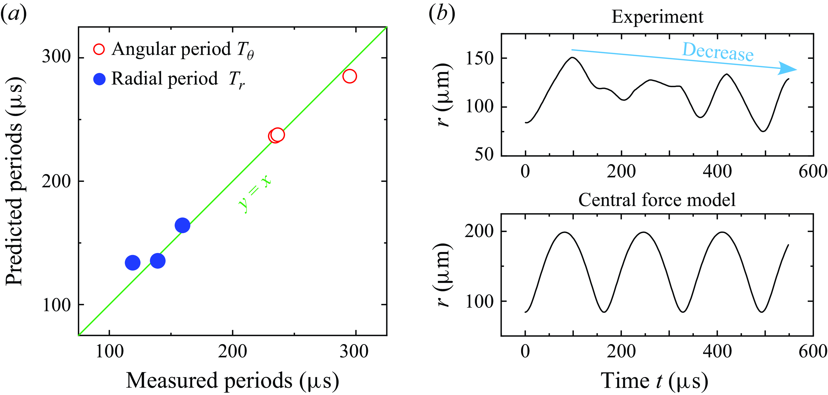
The main discrepancy is that the size of the measured orbit is smaller and shrinks over time, as highlighted by the downward trend of $r(t)$
in figure 7(b), which is inconsistent with the model. We believe the shrinking of the orbit is due to the air resistance and the variation in mass of the rims over time, which in turn results from the instabilities and the axial flow that will be discussed in the next section. Further studies on the internal fluid flow could improve the model’s accuracy.
$r(t)$
in figure 7(b), which is inconsistent with the model. We believe the shrinking of the orbit is due to the air resistance and the variation in mass of the rims over time, which in turn results from the instabilities and the axial flow that will be discussed in the next section. Further studies on the internal fluid flow could improve the model’s accuracy.
Although the analysis considers only the centre plane ( $z=0$
, or equivalently,
$z=0$
, or equivalently, $\beta =0$
), the central force model should remain applicable to off-centre planes by recognising that the corresponding initial velocity is
$\beta =0$
), the central force model should remain applicable to off-centre planes by recognising that the corresponding initial velocity is $v_\theta (0)=u_c \cos \beta$
. Recall that the kinematic model in (3.2) and figure 2 has already assumed the ribbon is a ruled surface by connecting two rims, with a satisfactory result. However, it is challenging to compare with experimental results because the orbits in off-centre planes drift outward along the axial direction, which will be discussed in the next section.
$v_\theta (0)=u_c \cos \beta$
. Recall that the kinematic model in (3.2) and figure 2 has already assumed the ribbon is a ruled surface by connecting two rims, with a satisfactory result. However, it is challenging to compare with experimental results because the orbits in off-centre planes drift outward along the axial direction, which will be discussed in the next section.
This system presents an unusual scenario that the central force is distance-independent (potential is linear), in contrast to the typical celestial orbits (inverse-square law) and harmonic oscillators (Hooke’s law). Other examples of systems with linear potential include the triangular quantum well in high-electron-mobility transistors (Harrison & Valavanis Reference Harrison and Valavanis2016, p. 116) and the quark confinement in mesons (Griffiths Reference Griffiths2020, p. 173).
4. Corrugations and ligaments
4.1. Phenomenology
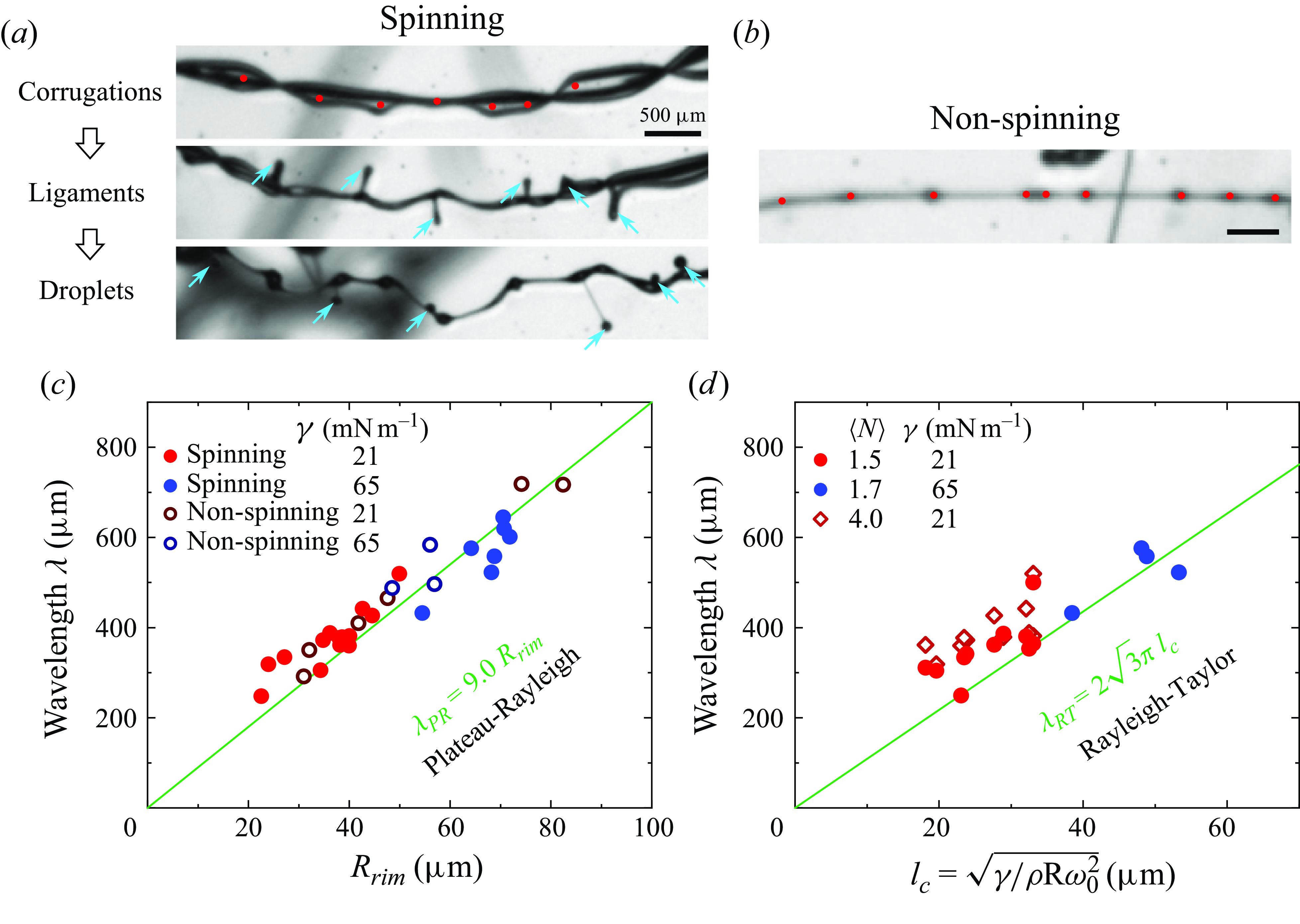
We observe that the rims become unstable during spinning at later times, forming corrugations along their lengths that grow into ligaments, which pinch off and eject secondary droplets, as shown in supplementary movie 7 and figure 8(a). The corrugations are marked by red dots. The ligaments are marked by cyan arrows. The instability is not uniquely associated with spinning, as similar corrugations are also observed without spinning. However, in the latter case, they do not grow into ligaments, as shown in figure 8(b).
We can distinguish this phenomenon from the previously discovered rim-splashing phenomenon by inspecting supplementary movie 7 and figure 8(a), even though they appear similar in still images (Néel et al. Reference Néel, Lhuissier and Villermaux2020; Tang et al. Reference Tang, Adcock and Mostert2024). First, unlike in rim splashing, the two rims of the ribbon have not coalesced when the ligaments develop. Second, in rim splashing, the ligaments are straight and perpendicular to the film. For the spinning ribbon, in contrast, the ligaments are rotating with the ribbon. For example, the centre ligament in supplementary movie 7 has been rotated by $\sim$
180
$\sim$
180 $^\circ$
. Third, under spinning conditions, ligaments that break up into droplets are observed at a Weber number lower than that in rim splashing on a planar surface. For comparison, under the current spinning conditions, the local Weber number is
$^\circ$
. Third, under spinning conditions, ligaments that break up into droplets are observed at a Weber number lower than that in rim splashing on a planar surface. For comparison, under the current spinning conditions, the local Weber number is $We_{loc}=\rho (2 u_c)^2 (2 R_{rim})/\gamma \sim 58$
, where
$We_{loc}=\rho (2 u_c)^2 (2 R_{rim})/\gamma \sim 58$
, where $R_{rim}$
is the rim radius. In rim splashing, ligaments that break up into droplets are observed at
$R_{rim}$
is the rim radius. In rim splashing, ligaments that break up into droplets are observed at $We_{loc}\gt 120$
(Néel et al. Reference Néel, Lhuissier and Villermaux2020; Tang et al. Reference Tang, Adcock and Mostert2024). Although we have not yet explored the threshold Weber number, the data suggest that ligaments and droplets can be produced at a lower Weber number in this rim-spinning case compared with the rim-splashing case.
$We_{loc}\gt 120$
(Néel et al. Reference Néel, Lhuissier and Villermaux2020; Tang et al. Reference Tang, Adcock and Mostert2024). Although we have not yet explored the threshold Weber number, the data suggest that ligaments and droplets can be produced at a lower Weber number in this rim-spinning case compared with the rim-splashing case.
Corrugations and ligaments. (a) The corrugations on the rims are marked by the red dots. The ligaments are marked by the cyan arrows. Corrugations grow into ligaments, pinch off and then eject secondary droplets due to the spinning. (b) For the non-spinning case, the corrugations do not grow into ligaments. (c) The measured average wavelength $\lambda$
agrees with the Plateau–Rayleigh instability (solid line) for both spinning (solid dots) and non-spinning (open dots) conditions at different rim radius
$\lambda$
agrees with the Plateau–Rayleigh instability (solid line) for both spinning (solid dots) and non-spinning (open dots) conditions at different rim radius $R_{rim}$
and surface tensions
$R_{rim}$
and surface tensions $\gamma$
. (d) The measured average wavelength
$\gamma$
. (d) The measured average wavelength $\lambda$
agrees with the Rayleigh–Taylor instability (solid line) at different capillary length
$\lambda$
agrees with the Rayleigh–Taylor instability (solid line) at different capillary length $l_c$
and surface tensions
$l_c$
and surface tensions $\gamma$
. The number of segments used in the averaging is denoted by
$\gamma$
. The number of segments used in the averaging is denoted by $N$
. Because
$N$
. Because $l_c$
is calculated based on the centre rotational speed
$l_c$
is calculated based on the centre rotational speed $\omega _0$
, the average wavelength based on fewer segments is more reliable.
$\omega _0$
, the average wavelength based on fewer segments is more reliable.
4.2. Plateau–Rayleigh and Rayleigh–Taylor instabilities
We plot the wavelength of the instability, $\lambda$
, against the rim radius,
$\lambda$
, against the rim radius, $R_{rim}$
, as shown in figure 8(c). The plot includes data for both spinning and non-spinning conditions for two different surface tensions. The average wavelength
$R_{rim}$
, as shown in figure 8(c). The plot includes data for both spinning and non-spinning conditions for two different surface tensions. The average wavelength $\lambda$
is calculated by dividing the length of a segment by the number of corrugations
$\lambda$
is calculated by dividing the length of a segment by the number of corrugations $N$
it contains. The rim radii are measured either just before spinning begins or, for the non-spinning case, just after the two rims coalesce. For all conditions studied here, the data agree with the Plateau–Rayleigh instability that
$N$
it contains. The rim radii are measured either just before spinning begins or, for the non-spinning case, just after the two rims coalesce. For all conditions studied here, the data agree with the Plateau–Rayleigh instability that $\lambda_{\textit{PR}} =9.0 R_{rim}$
(Rayleigh Reference Rayleigh1878; Wang et al. Reference Wang, Dandekar, Bustos, Poulain and Bourouiba2018). Therefore, it is very likely that the Plateau–Rayleigh instability leads to the corrugations, while the spinning motion is also essential for the formation of ligaments that pinch off into droplets.
$\lambda_{\textit{PR}} =9.0 R_{rim}$
(Rayleigh Reference Rayleigh1878; Wang et al. Reference Wang, Dandekar, Bustos, Poulain and Bourouiba2018). Therefore, it is very likely that the Plateau–Rayleigh instability leads to the corrugations, while the spinning motion is also essential for the formation of ligaments that pinch off into droplets.
On the other hand, the corrugation may also be induced by Rayleigh–Taylor instability under the centripetal acceleration caused by spinning (Eisenklam Reference Eisenklam1964). The wavelength of Rayleigh–Taylor instability is $\lambda _{RT} = 2\sqrt {3}\pi l_{c}$
, where
$\lambda _{RT} = 2\sqrt {3}\pi l_{c}$
, where $l_{c}=\sqrt {{\gamma }/(\rho a)}$
is the capillary length,
$l_{c}=\sqrt {{\gamma }/(\rho a)}$
is the capillary length, $\gamma$
is the surface tension,
$\gamma$
is the surface tension, $\rho$
is the liquid density,
$\rho$
is the liquid density, $a=R \omega ^2$
is the centripetal acceleration,
$a=R \omega ^2$
is the centripetal acceleration, $R$
is the rotation radius,
$R$
is the rotation radius, $\omega$
is the rotational speed.
$\omega$
is the rotational speed.
However, the rotational speed, and thus the centripetal acceleration, is not a constant but position dependent, along $z$
. It is highest at the centre plane (
$z$
. It is highest at the centre plane ( $z=0$
) and decreases towards the two ends. Focusing on the region near the centre plane, we take
$z=0$
) and decreases towards the two ends. Focusing on the region near the centre plane, we take $\omega \rightarrow \omega _0$
as the angular speed at
$\omega \rightarrow \omega _0$
as the angular speed at $z=0$
measured before the corrugations are observed. Correspondingly, the measured wavelengths are calculated using one or two segments nearest to the centre. The plot of the measured wavelengths versus the capillary length
$z=0$
measured before the corrugations are observed. Correspondingly, the measured wavelengths are calculated using one or two segments nearest to the centre. The plot of the measured wavelengths versus the capillary length $l_{c}=\sqrt {{\gamma }/(\rho R \omega _0^2)}$
is shown in figure 8(d) and is compared with the theoretical expression (solid line). The experimental data is close to the expected values for the Rayleigh–Taylor instability.
$l_{c}=\sqrt {{\gamma }/(\rho R \omega _0^2)}$
is shown in figure 8(d) and is compared with the theoretical expression (solid line). The experimental data is close to the expected values for the Rayleigh–Taylor instability.
In addition, we calculate another set of average wavelengths that includes more segments that are farther from the centre plane, as shown in figure 8(d) (open symbols). The average number of segments used is $\langle N \rangle =4.0$
. Nearly all of the obtained wavelengths increase. This agrees with the model that the rotational speed of the ribbon is highest at the centre plane and decreases towards the two ends, given that
$\langle N \rangle =4.0$
. Nearly all of the obtained wavelengths increase. This agrees with the model that the rotational speed of the ribbon is highest at the centre plane and decreases towards the two ends, given that $\lambda _{RT}\sim 1/\omega$
.
$\lambda _{RT}\sim 1/\omega$
.
We have shown that the measured wavelengths agree with both the Plateau–Rayleigh and Rayleigh–Taylor instabilities. Comparing the wavelengths of Plateau–Rayleigh and Rayleigh–Taylor instabilities, one can show that $\lambda _{RT} / \lambda _{PR}=1.2/\sqrt {\textit {Bo}}$
where
$\lambda _{RT} / \lambda _{PR}=1.2/\sqrt {\textit {Bo}}$
where $\textit {Bo}={\rho a R^2_{rim}}/{\gamma }$
is the local rim Bond number, in which the rim radius
$\textit {Bo}={\rho a R^2_{rim}}/{\gamma }$
is the local rim Bond number, in which the rim radius $R_{rim}$
is taken as the characteristic length, and
$R_{rim}$
is taken as the characteristic length, and $a$
is the acceleration. It is commonly found that
$a$
is the acceleration. It is commonly found that $\textit {Bo}\sim O(1)$
in different breakup scenarios (Wang et al. Reference Wang, Dandekar, Bustos, Poulain and Bourouiba2018), so that
$\textit {Bo}\sim O(1)$
in different breakup scenarios (Wang et al. Reference Wang, Dandekar, Bustos, Poulain and Bourouiba2018), so that $\lambda _{RT} \sim \lambda _{PR}$
. In our experiments, calculated from the rotational speed at the centre plane,
$\lambda _{RT} \sim \lambda _{PR}$
. In our experiments, calculated from the rotational speed at the centre plane, $Bo$
ranges from 1.5 to 4.6 so that the ratio
$Bo$
ranges from 1.5 to 4.6 so that the ratio $\lambda _{RT} / \lambda _{PR}$
ranges from 0.6 to 1.0. Therefore, the wavelengths of Plateau–Rayleigh and Rayleigh–Taylor instabilities are similar in magnitude under current experimental conditions.
$\lambda _{RT} / \lambda _{PR}$
ranges from 0.6 to 1.0. Therefore, the wavelengths of Plateau–Rayleigh and Rayleigh–Taylor instabilities are similar in magnitude under current experimental conditions.
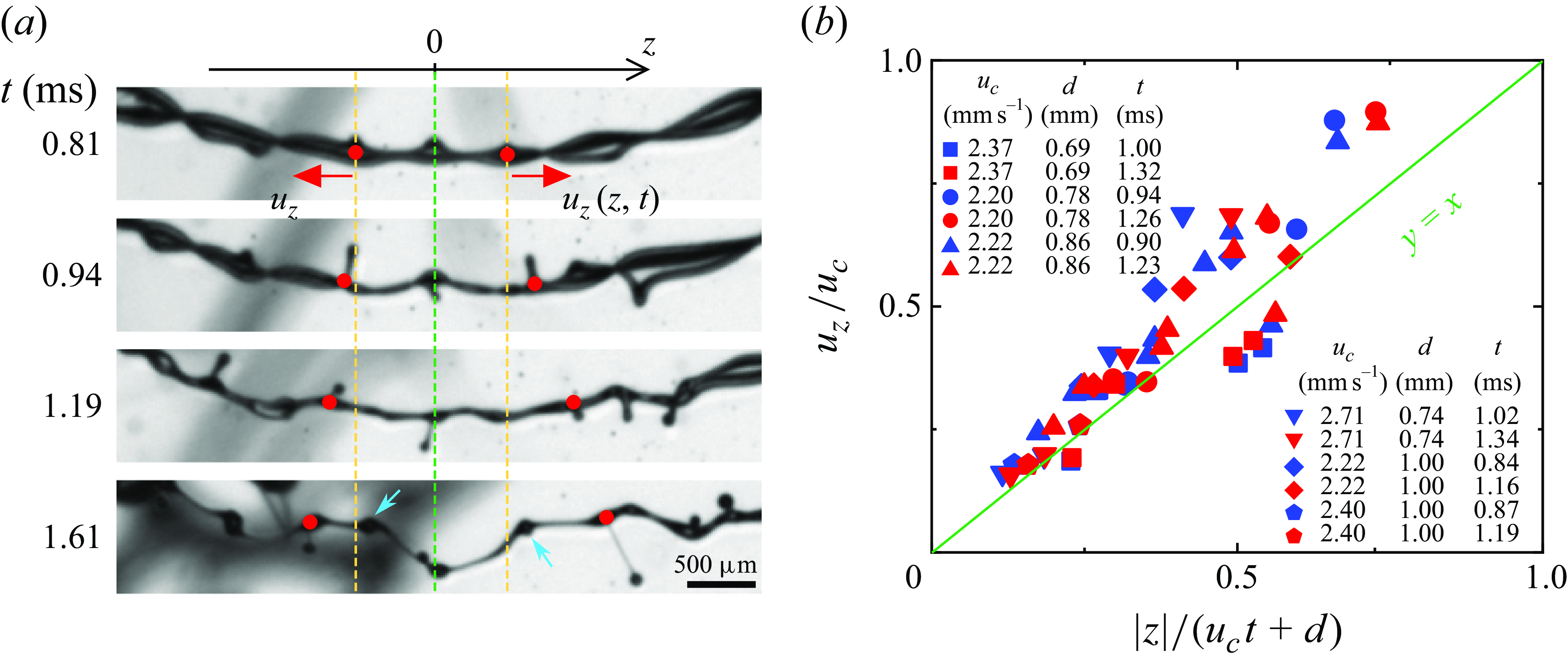
Outward axial flow. (a) Snapshots of the twisted ribbon at different times. The corrugations and ligaments (red dots) are moving outward with speed $u_z$
relative to the centre (
$u_z$
relative to the centre ( $z=0$
) of the twisted ribbon, confirming the existence of the outward axial flow. The blue arrows highlight the newly emerged corrugations at later times. (b) The speed of the outward axial flow
$z=0$
) of the twisted ribbon, confirming the existence of the outward axial flow. The blue arrows highlight the newly emerged corrugations at later times. (b) The speed of the outward axial flow $u_z$
measured at different conditions as shown in the legend. See also supplementary movie 7.
$u_z$
measured at different conditions as shown in the legend. See also supplementary movie 7.
4.3. Axial flow
The corrugations and ligaments are moving outward with speed $u_z$
relative to the centre (
$u_z$
relative to the centre ( $z=0$
) of the twisted ribbon, as indicated in figure 9(a), confirming the existence of the outward axial flow. It originates from the rims’ non-zero velocity component parallel to the rotation axis, as the rims move radially from the points of rupture before reaching the rotation axis. By (3.2), the axial flow speed
$z=0$
) of the twisted ribbon, as indicated in figure 9(a), confirming the existence of the outward axial flow. It originates from the rims’ non-zero velocity component parallel to the rotation axis, as the rims move radially from the points of rupture before reaching the rotation axis. By (3.2), the axial flow speed $u_z$
is given by
$u_z$
is given by
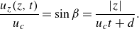 \begin{equation} \frac {u_z (z, t)}{u_c} = \sin \beta = \frac {|z|}{u_c t+d} . \end{equation}
This relation agrees with experimental data as shown in figure 9(b). Experimentally, $u_z$
is measured by tracking the positions of corrugations over time, and
$u_z$
is measured by tracking the positions of corrugations over time, and $d$
is measured as the distance between the ribbon and the smaller hole without considering the asymmetry.
$d$
is measured as the distance between the ribbon and the smaller hole without considering the asymmetry.
It is interesting that, by volume conservation, the outward flow would reduce the thickness of the sheet and the rim, adding complexity to the understanding of the rims’ orbit. Unfortunately, the resolution in our experiments is insufficient to quantify this change in thickness directly.
The axial flow also causes the emergence of new corrugations over time, as shown in the last row of figure 9(a) and supplementary movie 7. Due to the axial flow, the spacing between neighbouring corrugations or ligaments increases over time. When the spacing becomes sufficiently large relative to the wavelength of the instability, new corrugations begin to emerge. Such self-sustained population of corrugations has been studied previously in the rim of an expanding liquid sheet (Gordillo, Lhuissier & Villermaux Reference Gordillo, Lhuissier and Villermaux2014).
5. Conclusions
To conclude, we have explained the formation and evolution of spinning twisted ribbons. The ribbon forms when the rim deviates from the original curved surface due to insufficient centripetal force. This phenomenon is unique to curved films and does not occur in planar films. The geometry and motion of the ribbons are described by the kinematic model, the asymmetric kinematic model and the central force model. The calculated surfaces resemble the ribbons observed in the experiment. The positions of the conjunction points are accurately predicted. The mean curvature of the surface is small. The orbit of the rim is open and non-circular. Due to the spinning, corrugations along the rims grow into ligaments that eventually pinch off, ejecting secondary droplets. These corrugations very likely arise from the Plateau–Rayleigh and/or Rayleigh–Taylor instabilities, as the measured wavelengths agree with both models. This rim-spinning phenomenon is distinctly different from the rim splashing observed in previous studies, including its facilitation of droplet formation at lower Weber numbers. The ribbon contains an intrinsic outward axial flow, which leads to the emergence of new corrugations and variations in rim thickness. While this study focuses on experiments of multiple-hole rupture in corona splash, the underlying principles are likely applicable to other systems where twisted ribbons emerge.
Supplementary movies
Supplementary movies are available at https://doi.org/10.1017/jfm.2025.10299.
Acknowledgements
We acknowledge V. Mugundhan, A. Aguirre-Pablo, K. Dharmarajan, M. Lin, Z. Yang, A. Alhareth, F. Kamoliddinov and M. Kattoah for their help in experiments and fruitful discussions. We thank the referees for their thoughtful comments and valuable suggestions.
Funding
This work is financially supported by King Abdullah University of Science and Technology (KAUST) under grant numbers URF/1/2621-01-01 and BAS/1/1352-01-01.
Declaration of interests
The authors report no conflict of interest.
Data availability statement
All data is included in the manuscript and supplementary movies.
Author contributions
S.T.T. conceived the project; T.A., J.H.Y.L. and Y.L. built the experimental set-up; J.H.Y.L., Y.L. and S.T.T. performed the experiments; J.H.Y.L., Y.L. and S.T.T. analysed the data; J.H.Y.L. and Y.L. constructed the models; J.H.Y.L. and M.F.A. performed the numerical simulations; J.H.Y.L, Y.L. and S.T.T. wrote the manuscript.
Appendix A. Crown sheet composition
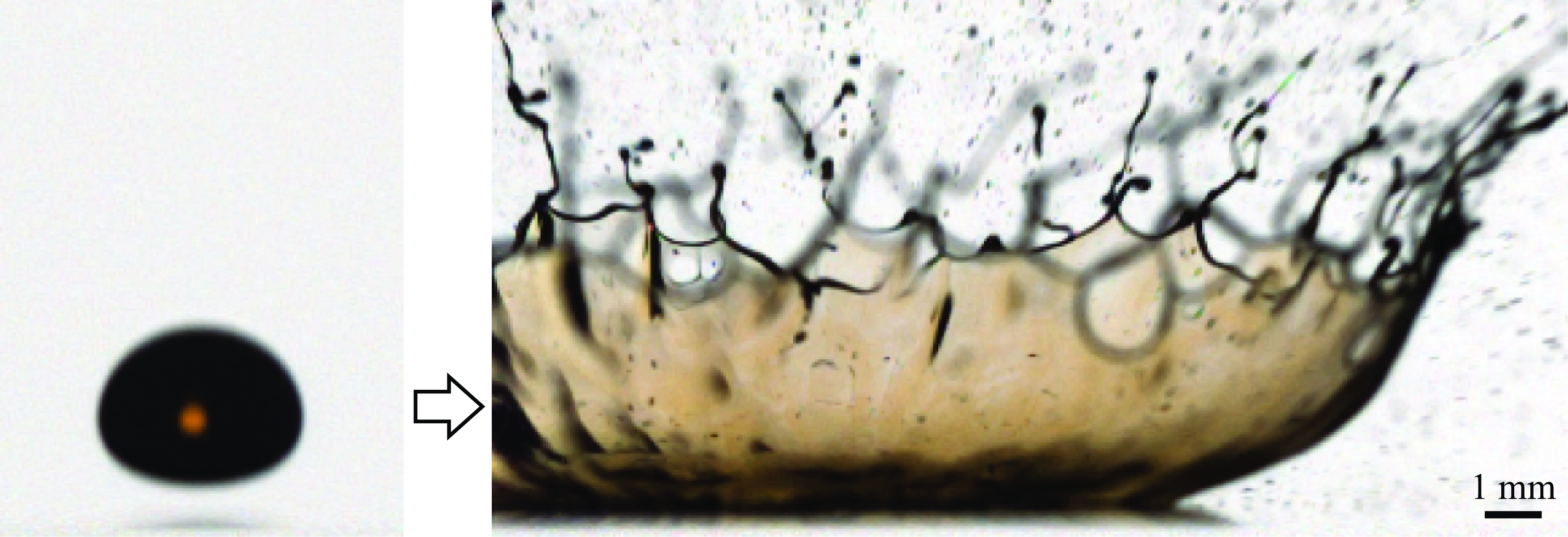
To confirm that the crown of the corona splash (i.e. the curved film) originates from the liquid in the drop, under our experimental conditions, rather than from the liquid film coating the glass slides, we conduct dyed-drop experiments, as shown in figure 10. The drop is a glycerol–water mixture dyed yellow with fluorescein (0.01wt $\%$
). From figure 10, we can see that the crown shows the same yellow colour as the drop.
$\%$
). From figure 10, we can see that the crown shows the same yellow colour as the drop.
Dyed-drop experiment indicates that the crown sheet originates from the liquid in the drop.
Appendix B. Correction of parallax error
On a curved surface, the plane of ruptures may not be parallel to the image plane of the camera, inducing errors in length measurements. We correct these parallax errors by the following method.
First, we use the side-view image to measure the local rotation angles (Euler angles) $\theta$
and
$\theta$
and $\phi$
, as shown in figure 11. The angle
$\phi$
, as shown in figure 11. The angle $\phi$
is read from the image directly, while the angle
$\phi$
is read from the image directly, while the angle $\theta$
is obtained, assuming axisymmetry, from the equation
$\theta$
is obtained, assuming axisymmetry, from the equation $\sin \theta =s/R_h$
, where
$\sin \theta =s/R_h$
, where $R_h$
is the horizontal radius of the crown,
$R_h$
is the horizontal radius of the crown, $s$
is the distance of the plane from the centre. A top-view drawing is provided in figure 11 for clarity.
$s$
is the distance of the plane from the centre. A top-view drawing is provided in figure 11 for clarity.
Next, we derive the formula to correct for the parallax errors in length measurements. The rotation matrix is
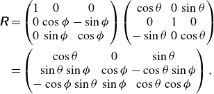 \begin{align} \unicode{x1D64D}&= \begin{pmatrix} 1 & 0 & 0\\ 0 & \cos \phi & -\sin \phi \\ 0 & \sin \phi & \cos \phi \\ \end{pmatrix} \begin{pmatrix} \cos \theta & 0 & \sin \theta \\ 0 & 1 & 0\\ -\sin \theta & 0 & \cos \theta \\ \end{pmatrix}\nonumber\\ &= \begin{pmatrix} \cos \theta & 0 & \sin \theta \\ \sin \theta \sin \phi & \cos \phi & -\cos \theta \sin \phi \\ -\cos \phi \sin \theta & \sin \phi & \cos \theta \cos \phi \\ \end{pmatrix}, \end{align}
while the projection matrix is
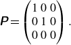 \begin{equation} \unicode{x1D64B}=\begin{pmatrix} 1 & 0 & 0\\ 0 & 1 & 0\\ 0 & 0 & 0\\ \end{pmatrix}. \end{equation}
Let $\boldsymbol {d} \equiv \begin{pmatrix} d_x\\d_y\\0\\ \end{pmatrix}$
be an arbitrary unit line on a plane, then
$\boldsymbol {d} \equiv \begin{pmatrix} d_x\\d_y\\0\\ \end{pmatrix}$
be an arbitrary unit line on a plane, then ${\boldsymbol {d}}' \equiv d'\begin{pmatrix} \cos \psi \\\sin \psi \\0\\ \end{pmatrix}$
is the rotated and projected line from
${\boldsymbol {d}}' \equiv d'\begin{pmatrix} \cos \psi \\\sin \psi \\0\\ \end{pmatrix}$
is the rotated and projected line from ${\boldsymbol d}'=\unicode{x1D64B}\unicode{x1D64D}{\boldsymbol d}$
, where the angle
${\boldsymbol d}'=\unicode{x1D64B}\unicode{x1D64D}{\boldsymbol d}$
, where the angle $\psi$
is measured from the x-axis. We then get
$\psi$
is measured from the x-axis. We then get
 \begin{align} d_{x} &= d'\cos \psi \sec \theta, \nonumber\\ d_{y} &= d' \left ( \sin \psi \sec \phi - \cos \psi \tan \theta \tan \phi \right ). \end{align}
Therefore, the ratio of the length before and after this transformation is
 \begin{equation} \Psi (\psi )=\frac {|\boldsymbol {d}|}{|\boldsymbol {d}'|}=\frac {d_x^2+d_y^2}{d'}=\sqrt {\left (\frac {\cos \psi }{\cos \theta }\right )^{2}+\left (\frac {\sin \psi }{\cos \phi }-\cos \psi \tan \theta \tan \phi \right )^{2}}, \end{equation}
where $\Psi$
is the ratio between the real length,
$\Psi$
is the ratio between the real length, $d$
, and the apparent length,
$d$
, and the apparent length, $d'$
. In other words, we can deduce the real length from the apparent length by
$d'$
. In other words, we can deduce the real length from the apparent length by $d=\Psi d'$
.
$d=\Psi d'$
.
Side and top views for parallax corrections.
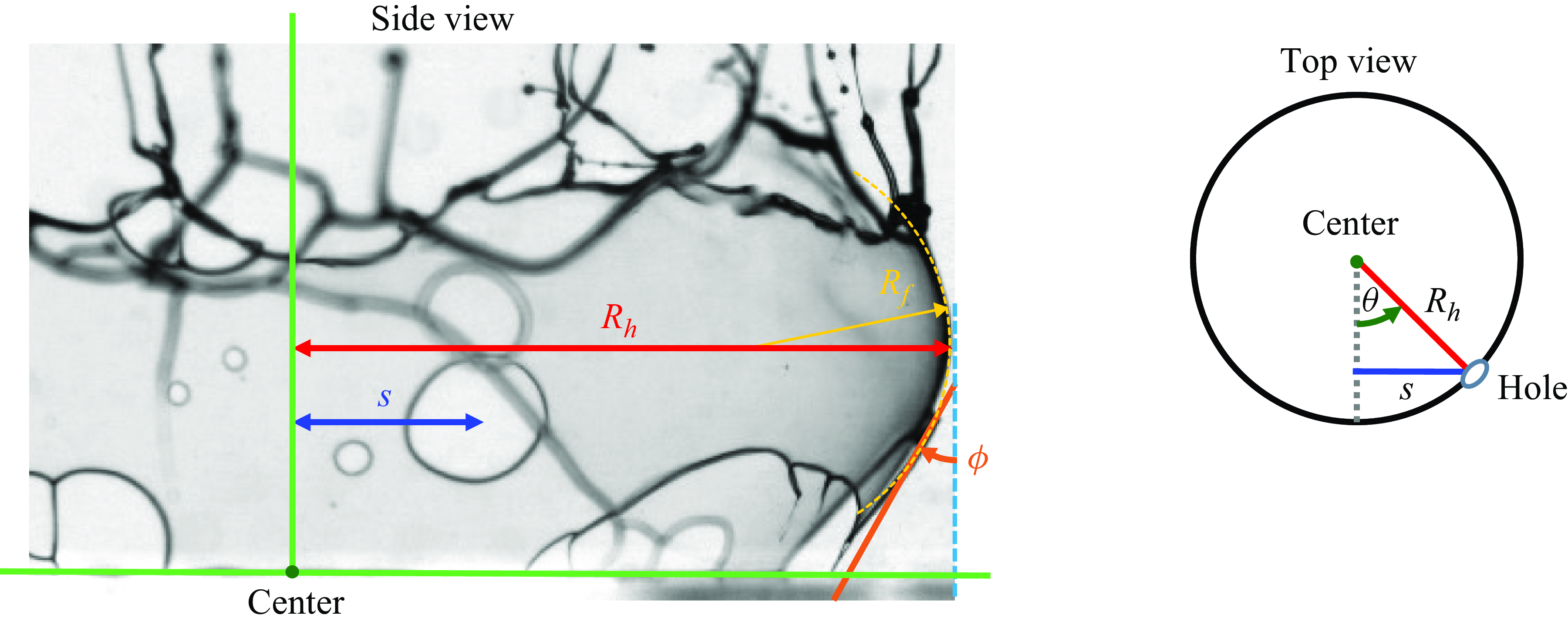
Image used to verify the parallax correction and (B4).
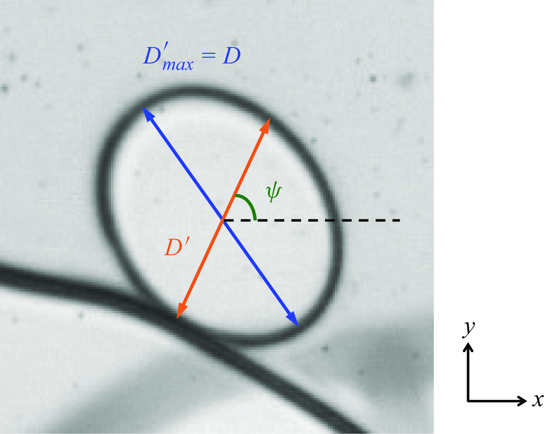
To verify (B4), we test it on the diameter of a hole. We make use of the facts that (i) physically, the capillary-driven hole is circular, and (ii) the apparent length of the longest axis of the transformed hole, $D'_{max}$
, is the real diameter of the hole,
$D'_{max}$
, is the real diameter of the hole, $D$
. Experimentally, we measure
$D$
. Experimentally, we measure $D'_{max}=D$
and the width of the hole along an arbitrary axis,
$D'_{max}=D$
and the width of the hole along an arbitrary axis, $D'$
, as shown in figure 12. We calculate the ratio
$D'$
, as shown in figure 12. We calculate the ratio $D/D'$
and compare it with the ratio
$D/D'$
and compare it with the ratio $\Psi$
deduced by (B4). In the example in figure 12, for
$\Psi$
deduced by (B4). In the example in figure 12, for $\psi =59.5^{\circ }$
,
$\psi =59.5^{\circ }$
, $\theta =-33.6^{\circ }$
,
$\theta =-33.6^{\circ }$
, $\phi =27.5^{\circ }$
, we get
$\phi =27.5^{\circ }$
, we get $D/D'=1.256$
and
$D/D'=1.256$
and $\Psi = 1.259$
. The measured ratio and the calculated ratio are very close, verifying that (B4) is correct.
$\Psi = 1.259$
. The measured ratio and the calculated ratio are very close, verifying that (B4) is correct.


 Open access

