


1 Introduction
Particle damping provides a promising method to reduce vibration amplitudes. Especially for lightweight design, damping technologies are very important. A minimized weight, which usually causes stiffness and reduction in strength, often results in an increase in vibration amplitudes. Here, particle damping poses a good opportunity to reduce vibrations of lightweight structures, as only little weight needs to be added to reduce vibration amplitudes (Panossian Reference Panossian2006). Particle damping is a passive damping technology using granular material within small cavities in the vibrating structure or within enclosures as attachment. Energy is dissipated by inelastic particle-to-wall and particle-to-particle collisions and friction. Though the technique seems simple and promising with applications to be found in the literature, it is difficult to predict the damping properties. So far, all modelling approaches as design methods for engineering decision-making have been limited by technical restrictions. First, due to the naturally occurring nonlinear particle behaviour, numerical predictions are either approximations to equivalent models or have limited applicability. Additionally, a large amount of experimental testing is necessary to derive equivalent models. Second, when detailed physical models at the particle level are used, the numerical prediction is highly time-consuming, requiring a high computational effort. This inhibits the accomplishment of many design iterations.
The underlying problem designing particle damping is described by Pourtavakoli et al. (Reference Pourtavakoli, Parteli and Pöschel2016). They state that the dissipative properties of granular materials are still poorly understood because the physical mechanisms occur at a very small scale. The result of this is that trial and error is still frequently employed to design damping properties. Additionally, the large number of design parameters increases the effort required to determine an optimum configuration. This adds to the difficulty of applying particle damping to industrial applications.
For these reasons and because of its ability to improve lightweight design, there is an industrial need for validated design approaches on the use of damping as an additional design parameter within structural optimization. Methodical approaches for the product development process that consider experimental and numerical steps need to be researched in order to make the design more efficient. This is not only true for the design of particle damping but also for other damping technologies.
In this paper, a new approach using frequency based substructuring (FBS) by Klerk et al. (Reference Klerk, Rixen and Jong2006) is used to predict particle damping. The FBS approach allows fast calculation and leads to design optimization, with its many design iterations becoming feasible. Furthermore, FBS reduces the effort to model nonlinear particle behaviour since experimentally characterized substructure models can be incorporated into the full system model. Thus, by separating the particle system from the rest of the system, it is possible to combine an experimental model with simulation data in a so-called hybrid frequency based assembly (FBA). The first results were published in a previous paper (Oltmann et al. Reference Oltmann, Hartwich, Krause, Sas, Moens and van de Walle2018). For the research outlined in this paper, the previous work is improved in some points. Besides, tests with new particle dampers and investigations on different excitation levels are added.
Above all, this study focuses on the presentation of an optimization framework using FBS for the design optimization of particle damping and weight of lightweight structures subjected to stationary dynamic loads. Not only the particle damping configuration is investigated but also whether added particle mass can be compensated by material savings or whether the increased damping would even allow a weight reduction of the total system. This is an essential part of the research since varying the structural properties may cause different damping behaviours and vice versa. The underlying research question investigated is whether the linear FBS coupling is appropriate to predict the dynamic behaviour sufficiently. Furthermore, sweep vibration tests using particle damping to reduce the vibration amplification of a honeycomb sandwich structure are carried out. Different particle enclosures are printed by additive manufacturing and are attached to the structure. Based on the numerical and experimental results, the application of the FBS approach is discussed with respect to engineering design.
1.1 Particle damping
Particle dampers (PD) are cavities partially filled with small particles of variable material. The particles are either directly inserted into existing enclosures (non-obstructive particle damping) of the primary structure or they can be attached to a vibrating structure at a location with high displacement amplitudes (Michon et al. Reference Michon, Almajid and Aridon2013, p. 536). For particle damping, a few damping mechanisms are relevant to describe the overall dissipation. First, there are non-elastic particle–particle and particle–wall collisions that induce damping, as indicated in Figure 1. Furthermore, friction between particles and particle–wall friction add additional dissipation.
Particle damping – working principle. Adapted from (Oltmann et al. Reference Oltmann, Hartwich, Krause, Sas, Moens and van de Walle2018).

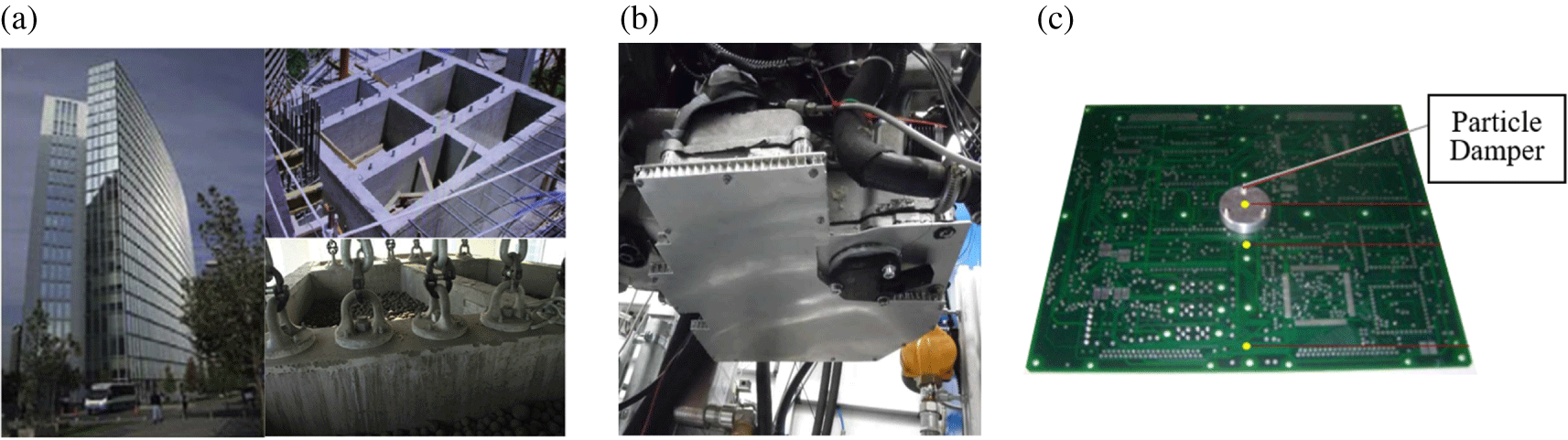
The past 50 years have seen the introduction of the application of impact masses as an absorbing source of vibration of structures, machines, and multi-storey buildings (Ibrahim Reference Ibrahim2009). The applications differ from a very large to a small scale. This shows the exceptional capabilities of this simple but effective technology. Three examples from different applications of entirely different sizes are shown in Figure 2.
Application of particle damping technology in industry. (a) Parque Arauco building in Chile (Lu et al. Reference Lu, Lu, Lu and Masri2012). (b) Oil pan bottom of a combustion engine (Koch et al. Reference Koch, Duvigneau, Orszulik, Gabbert and Woschke2017). (c) Capsule on a circuit board (Veeramuthuvel et al. Reference Veeramuthuvel, Sairajan and Shankar2016).
Regarding the properties of particle damping, the literature states a number of qualitative findings. First, the damping behaviour of granular materials is highly nonlinear due to impacts and sliding between the particles (Duvigneau et al. Reference Duvigneau, Koch, Woschke and Gabbert2016; Fowler et al. Reference Fowler, Flint and Olson2001, p. 1). In most publications, the nonlinearity is indicated as being dependent on the excitation amplitude. This closely correlates with the free space the particles have within an enclosure. However, this is rather a macroscopic effect since the different dissipation effects occur at the micro- (particle) level. There are only a few sources that have investigated this in more detail (Wong et al. Reference Wong, Daniel and Rongong2009; Zhao et al. Reference Zhao, Zhong, He and Schlaberg2014; Pourtavakoli et al. Reference Pourtavakoli, Parteli and Pöschel2016). A problem is that there are no standard micro-level measurement guidelines or standardized test set-ups, which would certainly improve research collaboration.
Another property of particle damping is found to be a broadband damping technique (Lui Reference Lui2011; Michon et al. Reference Michon, Almajid and Aridon2013). Furthermore, a few research papers state that for typical particles (e.g. metal and sand), the damping performance is independent of environmental conditions such as temperature or moisture. In comparison to viscoelastic dampers, this can be an advantage in many applications (Yokomichi et al. Reference Yokomichi, Araki, Jinnouchi and Inoue1996; Michon et al. Reference Michon, Almajid and Aridon2013).
1.1.1 Modelling and Design of Particle Dampers
Generally, numerical modelling of particle damping is difficult (Wong et al. Reference Wong, Daniel and Rongong2009; Lui Reference Lui2011). Different modelling approaches can be found within current research. Many studies focus on analytical models to predict the damping behaviour, such as equivalent models with a single degree of freedom (S-DoF). Such approaches have continuously been investigated to the present day (Yokomichi et al. Reference Yokomichi, Araki, Jinnouchi and Inoue1996; Friend & Kinra Reference Friend and Kinra2000; Michon et al. Reference Michon, Almajid and Aridon2013). For simplified parametric models, the problem so far is the high number of design parameters for particle damping compared to the number of variables existing for this type of modelling approach (Wong et al. Reference Wong, Daniel and Rongong2009). Thus, the models are only valid within their investigated operating range. However, they do allow fast calculations of a system response and are therefore still a part of many investigations.
Another approach to predict particle damping follows a hydrodynamic approach based on the similarities of molecular or gas liquid behaviour to particle movement. This approach is used especially when the number of particles is high. Despite some promising examples of the modelling of nonlinear particle behaviour, the approach remains at a fundamental research level. Previously, the approach has varied greatly in the choice of the identification system (box division) used to estimate the flow field values. It is therefore still a highly uncertain approach (Wong et al. Reference Wong, Daniel and Rongong2009).
At present, the discrete element method (DEM) is used by many researchers to exactly model particle behaviour. In comparison to other approaches, this is the most general method for predicting particle damping, as it consists of modelling the particles itself. Many studies could have involved the successful application of the DEM (Wong et al. Reference Wong, Daniel and Rongong2009; Lu et al. Reference Lu, Lu, Lu and Masri2012; Saeki et al. Reference Saeki, Mizoguchi and Bitoh2018). However, the method is limited by, for example, the number of particles due to a high amount of information required for computation (Saeki et al. Reference Saeki, Mizoguchi and Bitoh2018). It is not yet an efficient tool for vibrational problems, and especially problematic for design optimization, since it requires multiple runs of different PD configurations. The method also has other drawbacks such as the requirement of various assumptions and detailed material (Veeramuthuvel et al. Reference Veeramuthuvel, Sairajan and Shankar2016) properties.
A novel approach has been developed by Veeramuthuvel et al. (Reference Veeramuthuvel, Sairajan and Shankar2016). In considering the complexities of the problem, it has been proposed that an artificial neural network be used for the correlation between design parameters and damping performance, based on an experimental database. Recently, Wang et al. (Reference Wang, Liu, Tian, Wei and Jiang2019) proposed a semi-empirical method and compared this to DEM modelling. In this study, the experimentally driven semi-empirical approach revealed better performance in predicting particle damping than the DEM approach.
Generally, few numerical studies exist to predict particle damping, and all approaches still struggle to predict nonlinear particle damping, requiring high computational power or intense experimental testing for application as a design method for engineering decision-making. Consequently, simple trial-and-error approaches to optimize particle damping design are still very common (Lui Reference Lui2011; Sánchez et al. Reference Sánchez, Rosenthal and Pugnaloni2012; Michon et al. Reference Michon, Almajid and Aridon2013). A qualitative design approach based on a ‘rule of thumb’ for various parameters is presented by Fowler et al. (Reference Fowler, Flint and Olson2001). Recently, Koch et al. (Reference Koch, Duvigneau, Orszulik, Gabbert and Woschke2017) proved the potential of the defined partial filling with granular materials of a honeycomb structure within the oil pan bottom of an engine in order to reduce sound emissions. They also used an experimental approach to optimize placing particle dampers. However, another main issue for the design of particle dampers is the high number of design parameters, including the geometry of the container, material properties like stiffness or surface roughness, the shape or the filling ratio and so on (Wong et al. Reference Wong, Daniel and Rongong2009).
The number of possible design parameters and the problem of modelling nonlinear damping effects are the main reasons why the capabilities of particle damping have not been systematically proved and why experimental testing is by now the most reliable design approach. For these reasons, there is a need for design methods in order to make particle damping design more efficient and thus applicable to a broader field of applications. To reduce the amount of testing, especially large-scale testing, and to reduce computation time, an FBS approach can be utilized. In this way, design optimization becomes feasible. Therefore, an FBS-optimization approach for particle damping design is presented and discussed.
1.2 Frequency based substructuring
In product development, complex structures can be divided into different smaller subsystems or substructures to facilitate design processes. In this paper, using FBS, a nonlinear mechanical structure shall be partitioned into smaller substructures to facilitate design optimization. The underlying theory for FBS is based on the analysis of the linear structural dynamic behaviour in the frequency domain and was published earlier (Jetmundsen et al. Reference Jetmundsen, Bielawa and Flannelly1988). In the frequency domain, a system is described by frequency response functions (FRFs) for a chosen set of DoFs. The objective of FBS is to predict the dynamic behaviour of a system made of subparts on the basis of FRFs of the uncoupled substructures (Klerk et al. Reference Klerk, Rixen and Jong2006). In 2008, De Klerk et al. published a general framework for dynamic substructuring. They introduced the so-called dual assembly, which facilitates the way for synthesizing the overall FRF matrix. Accordingly, taking a DoF vector  $\mathbf{u}$, the general equation of motion in the frequency domain is
 $$\begin{eqnarray}\displaystyle \mathbf{Z}(\unicode[STIX]{x1D714})\mathbf{u}(\unicode[STIX]{x1D714}) & = & \displaystyle \mathbf{f}(\unicode[STIX]{x1D714})+\mathbf{g}(\unicode[STIX]{x1D714})\end{eqnarray}$$
 $$\begin{eqnarray}\displaystyle \mathbf{Bu}(\unicode[STIX]{x1D714}) & = & \displaystyle \mathbf{0}\end{eqnarray}$$
 $$\begin{eqnarray}\displaystyle \mathbf{L}^{\mathbf{T}}(\unicode[STIX]{x1D714}) & = & \displaystyle \mathbf{0},\end{eqnarray}$$
 where  $\mathbf{Z}$ consists of the dynamic stiffness matrices of the different substructures; $\mathbf{f}$ is the global vector of external forces; B and L are Boolean matrices; $\mathbf{B}$ is defined as the interface compatibility of connecting DoFs; and $\mathbf{L}$ is the equilibrium of connection forces $\mathbf{g}$ (Klerk et al. Reference Klerk, Rixen and Jong2006). Introducing the Lagrange multiplier $\boldsymbol{\unicode[STIX]{x1D706}}$ such that $\mathbf{g}=-\mathbf{B}^{T}\boldsymbol{\unicode[STIX]{x1D706}}$, the so-called dual assembly in matrix form is obtained as follows:

The Lagrange multiplier  $\text{\unicode[STIX]{x1D706}}$ represents the internal connection forces. Solving the equation in the first row for u with $\mathbf{Z}^{-1}=\mathbf{Y}$ yields

where  $\mathbf{Y}$ is the uncoupled receptance matrix of the whole mechanical system in block diagonal form, e.g., for two subsystems A and B:

Inserting  $\mathbf{u}$ (
) into the second row of (
4), one finds
 $$\begin{eqnarray}\displaystyle \mathbf{B}(\mathbf{Yf}-\mathbf{Y}\mathbf{B}^{T}\boldsymbol{\unicode[STIX]{x1D706}}) & = & \displaystyle \mathbf{0}\end{eqnarray}$$
 $$\begin{eqnarray}\displaystyle \Rightarrow \boldsymbol{\unicode[STIX]{x1D706}} & = & \displaystyle (\mathbf{BY}\mathbf{B}^{T})^{\text{-1}}\mathbf{BYf}.\end{eqnarray}$$
Inserting (8) into (
5) leads to the coupled transfer function matrix  $\mathbf{Y}_{\mathbf{C}}(\unicode[STIX]{x1D714})$
 $$\begin{eqnarray}\displaystyle \mathbf{u} & = & \displaystyle \underbrace{(\mathbf{Y}-\mathbf{Y}\mathbf{B}^{T}(\mathbf{BY}\mathbf{B}^{T})^{\text{-1}}\mathbf{BY})}_{}\mathbf{f}\end{eqnarray}$$
 $$\begin{eqnarray}\displaystyle \mathbf{u} & = & \displaystyle \mathbf{Y}_{\mathbf{C}}(\unicode[STIX]{x1D714})\mathbf{f}.\end{eqnarray}$$
The application of the FBS approach as well as a framework for particle damping optimization is presented in the following.
2 FBS coupling of particle damper unit cells
The concept behind the FBS approach in this study is to separate the linear and nonlinear parts of the full system. The mechanical system under investigation is divided into the primary structure and the particle system. Both subsystems can be further separated into a number of substructures. When coupling particle systems, the advantage of the FBS is that it allows the determination of FRFs through both simulation and experimental testing, which can then be used for an assembly of the full system model. In this way, a consideration of particle damping can be made without detailed modelling of the real physics (nonlinearity and frequency dependency), given that experimental tests can be employed to determine the input and the output of the system.
The FBS coupling is explained in detail by the attachment of a particle damper to a lightweight honeycomb sandwich panel. The substructure definition is given in Figure 3.
Investigated mechanical system (Oltmann et al. Reference Oltmann, Hartwich, Krause, Sas, Moens and van de Walle2018).

The honeycomb sandwich panel, plus its fixture, serves as the primary structure to be damped. The honeycomb panel is clamped at one end and is subjected to base point excitation. The particle dampers consist of the panel cavity with the particle filling constituting the second substructure. The FRF of the particle damper is determined experimentally, and the FRF of the honeycomb panel is estimated by FE-simulation. Finally, with the so-called hybrid FBA, using test (particle cavity) and simulation (lightweight structure) results, the dynamic behaviour of the full system can be determined.
Generally, the new approach for particle damping predictions is based on the consideration of the particle system as a so-called black box. The describing function is the receptance FRF of the particle damper (see Figure 4(a)). Thus, for design purposes, different particle units can, for example, be coupled at different locations of the primary structure to investigate, among other things, the optimum area of application or the number of particles units to be used.
Black box approach for particle damping and definition of system boundary of a particle damper for the frequency based assembly.

The required substructure definition is achieved, as indicated, for a simple particle system in Figure 4(b). The obvious requirement is that there is an enclosure – the particle cavity – that particles collide with. In this way, the mechanical energy is transferred to the surrounding structure. For all applications, a boundary definition as indicated is required, which is also the case under circumstances in which particles are incorporated into hollow structures without extra cavities attached. For the FBS coupling, as input and output quantities, the displacements and forces on either side are required in order to determine its receptances (alternatively, mobility or accelerance).
2.1 FBS coupling of particle damper unit cell
For the damping of the sandwich panel, different PDs comprising the cavity and the particles are used. Each PD can be regarded as a unit cell damper that can be used at different locations along the panel. Furthermore, to find out the optimum area of application, several PDs can be distributed and attached to the panel at different points.
The full system is modelled using the four DoFs 1–4 as indicated in Figure 5. At each DoF, information regarding force and acceleration is required. For the coupling of the PD to the panel, a rigid multipoint connection is used, via interpolation constraint elements (RBE2) in the FE-model. The interface definition between the PD and the sandwich panel is shown in Figure 5. In this way, each PD unit cell is linked to the FE-model at a single node.
As indicated in the figure, the coupling of the PD to the primary structure is reduced to a single DoF #3. The damper is only described by one FRF at the interface to the primary structure since there are no further relevant internal DoFs in the particle system. It is further surmised that the PD can be represented through a 1D frequency response  $\text{Y}_{\text{PD}}$ in the direction of the main particle movement. For the design optimization, the interface DoF 3 and its corresponding rigid elements are positioned dependent on the position of the particle damper to be applied.
With the chosen set of DoFs (Figure 5) for the substructure, the FRF of the PD follows:
 $$\begin{eqnarray}\text{Y}_{\text{PD}}=\text{Y}_{44}\end{eqnarray}$$
and for the FRF matrix of the sandwich panel:

Consequently, the uncoupled FRF matrices Y can be written as

Coupling the displacements at DoFs 3 and 4 leads to
 $$\begin{eqnarray}0=u_{3}-u_{4}.\end{eqnarray}$$
Based on (2), the Boolean matrix B is set to

The coupled FRF matrix  $\text{Y}_{C}$ can be calculated using (10):
 $$\begin{eqnarray}\text{Y}_{C}=\text{Y-Y}\text{B}^{T}(\text{BY}\text{B}^{T})^{\text{-1}}\text{BY}.\end{eqnarray}$$
Inserting (
13) and (
15) leads to

In the frequency domain, the receptances can be distinguished from the mobility or accelerance by multiplication of  $\text{Y}$ with $j\unicode[STIX]{x1D714}$ or $-\unicode[STIX]{x1D714}^{2}$, respectively. Thus, the mobility and the accelerance can also be used.
Definition of system degree of freedoms 1–4 and FE coupling point for a particle damper via rigid link (RBE2) elements. Adapted from (Oltmann et al. Reference Oltmann, Hartwich, Krause, Sas, Moens and van de Walle2018).

Through the use of this equation, the maximum vibration amplitude at the fixed DoF #2 can be calculated. For the following experimental validation, the acceleration amplification (transmissibility T) from DoF #1 to DoF #2 is compared to the test results.
2.2 Experimental analysis of coupled system
In this section, the experimental characterization of single substructures as well as of the coupled system is presented. For the experimental investigations, a sandwich panel (see Figure 6(a)) is clamped at one end and excited with classical base point excitation at different excitation levels. It is the same system as investigated in (Oltmann et al. Reference Oltmann, Seemann and Krause2015). The sandwich panel is a typical aircraft interior sandwich panel used for lightweight structures such as lavatories, galleys and lining component. The panel consists of glass fibre fabric reinforced phenolic resin prepreg face sheets (PHG600-68-50/44) and a Nomex honeycomb core (cell size 3.2 mm, density 48 kg/m3).
(a) Test set-up for sine-sweep testing of honeycomb sandwich panel. (b) The three different sizes of particle cavities.

The test set-up is shown in Figure 6(a). For the vibration tests, a frequency sweep at a constant amplitude of 0.35 g (3,43 m/s2) within a frequency range of 5–25 Hz is carried out using a hydraulic shaker. The sweep velocity is 0.5 octave/min. The panel is clamped with an aluminium fixture at one end (clamping area = 70×190 mm), and it freely vibrates at the top. To determine the FRFs of the clamped sandwich panel, the acceleration is measured on the fixture at the bottom and the top of the panel. The acceleration is measured as input and output signals by PCB-356A02 triaxial 500g ICP acceleration sensors (<1% linearity up to 400 g). Furthermore, a 5 kN 6D load cell (ME-K6D68) is used to measure the load of the input excitation. All measurements are done at a sampling rate of 600 Hz, and for the data acquisition, a universal HBM QuantumX amplifier system is used. For test evaluation, the FRF in the out-of-plane direction of the panel is determined dividing the Fast Fourier Transform (FFT) from the output and the input acceleration signal without further postprocessing. Structural damping for the FE-simulation of the panel without PD is determined via the half-power-bandwidth method.
For the study, different PDs are attached to the honeycomb sandwich panels using petro wax (PCB Synotech), which is also used to attach acceleration sensors. Compared to liquid bonding adhesive, no differences in the dynamic behaviour could be seen. Overall, three sizes of PDs are used – small, medium and large size cavities with 4 mm drill holes are distributed equally in the direction of excitation (see Figure 6(b)). The precise dimensions are given in Table 1. The size of the particle cavity and the number of holes double with increasing dimensions. The cavities are 3D-printed with ABS material. The particle material used is commercial quartz sand with a defined particle size of 0.1–0.4 mm. Filling ratios  $\unicode[STIX]{x1D717}$ of 25%, 50% and 75% are realized for every PD. The PDs are closed with a top plate, also made from ABS material, and an adhesive tape from the outside to prevent sand particles from getting out.
Dimensions of the particle damper including the filling ratio and the associated mass

For the evaluation of the measurement results, the magnitude of the transmissibility, the amplification, is shown in Figure 7 for some PDs compared to the panel without damping treatment. As reference, the mass of the honeycomb sandwich with two layers is 709 g. The FRFs shown are not filtered, and the corresponding FFTs of the input and output signals are calculated with the maximum frequency resolution. In this case, it is typical to have some noise especially for increasing frequency (Pintelon & Schoukens Reference Pintelon and Schoukens2012). Furthermore, during the experiments, the coherence was constantly checked, and strong deviations from 1.0 (indicating, e.g., a large amount of noise or nonlinearities) were not found.
Test results for particle damping at panel top with 50% filling ratio.

In all FRFs, a large decrease in amplification of up to 30% of the reference tests can be seen. The frequency shift, mainly due to the mass increase towards a lower resonance frequency, is about 6 Hz from 17 Hz to a minimum of 11 Hz. One of the main reasons for the large frequency shift is the amount of mass that is simply added by the particle cavity. However, the mass of the cavity alone does not overly lower the amplification. A fixed mass of 400 grams leads to a frequency shift but only to a slight reduction of amplification from 62 to 57 (see Figure 7). Therefore, the particle damping can account for the damping effect. Generally, the results show that with increasing particle mass, the amplification can be further reduced, as is already stated in the literature. However, this demonstrates the capability of particle damping to reduce the amplification of the investigated structure.
Studying the filling ratio of the small PD revealed some typical nonlinear behaviour. In Figure 8, the maximum amplification within in the excitation range from 5 to 25 Hz is shown for different excitation levels and positions on the panel. As expected, the amplification decreases from the top position (1) to the middle (5) of the panel. For a filling ratio of 25% at the mid-position (5), there is no damping and the panel without PD is even slightly below the one with the damper. However, this is within 2% percent measurement deviation. Therefore this is simply seen to be without a damping effect. But, over all tests, the PDs may reduce the amplification up to 30% of the reference.
Maximum amplification vs. excitation level for the small PD with different filling ratios at 5 positions (from top to the middle, 1–5) of the sandwich panel.

However, for an increasing excitation level, the reduction of the maximum amplification by PD decreases with respect to the vibration amplitude of panels without PD. This is due to an increase in the overall structural damping – mainly interface and material damping, because with increasing excitation level, the maximum amplification of the panels without PD decreases as well. In contrast, the amplitude reduction due to PD does not increase to the same amount or for some cases even decreases.
For PDs with 25% and 50% particles, the amplitude decreases or is nearly constant with increasing excitation level. However, the PD filled with 75% shows a different behaviour. The PD has the best performance at lower excitation levels in contrast to the others. This can be explained by the small clearance gap within the PD holes. With increasing excitation level, the particles move in phase with the excitation and the impact acceleration decreases.
2.2.1 Determination of substructure FRFs
In this part, it is shown how the two substructures used for the FBS coupling are derived. For the honeycomb panel, an FE-model is implemented in order to calculate all FRFs according to (11). Moreover, the experimental tests to determine the PD-FRF are shown. Based on these results, the coupled FRF matrix  $\text{Y}_{C}$ is calculated. Finally, in Section 2.3, the results are compared to experimental tests.
2.2.2 Numerical substructure characterization of sandwich panel
For the numerical model of the sandwich panel, a simple FE-model (see Figure 3) is used to determine the FRF matrix  $\text{Y}_{\text{Panel}}$ (12). A harmonic excitation is implemented with the large mass method in order to apply a constant base point acceleration. For the FE-simulation, shell elements are used to model the sandwich panel, including glass fibre face sheets and the honeycomb core. In order to have realistic dynamic behaviour rather than having a free–free boundary, the fixture is included in the model. To determine the dynamic behaviour for the panels without PD, a damping value is evaluated experimentally for each excitation level and implemented in the FE-model as a structural damping coefficient. The material properties of the honeycomb core and the damping properties for different excitations have been derived in previous studies (Oltmann et al. Reference Oltmann, Seemann and Krause2015; Oltmann et al. Reference Oltmann, Hartwich, Krause, Sas, Moens and van de Walle2018). For the calculation of modal frequency response, MSC.Nastran Sol 111 is used as a solver.
2.2.3 Experimental substructure characterization of particle damper
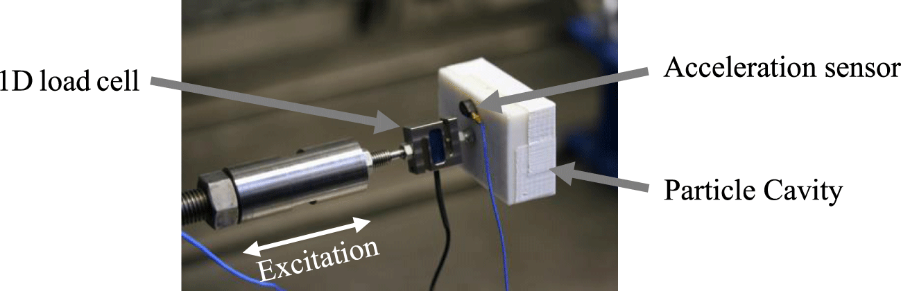
To determine the FRF of the PD, tests on a hydraulic shaker are carried out. These are especially appropriate for low frequency excitation. In Figure 9, the test set-up on the hydraulic shaker is shown in detail. As for the sandwich panel, the FRF shall be determined using a frequency sweep at a constant amplitude and a sweep rate of 0.5 octaves/minute. For the test, a constant acceleration of 1 g ( $=$ 9.81 m/s2) is chosen in order to have sufficient particle movement. The interface load is measured by a 1D-100N load cell (ME-KD24s) and the acceleration is measured with a lightweight (0.8 g) 50g-ICP acceleration sensor (PCB-352A24). The measured time signals are transformed into the frequency domain. The detailed process can be found in Oltmann et al. (Reference Oltmann, Hartwich, Krause, Sas, Moens and van de Walle2018).
Test set-up for experimental substructure characterization of the particle damper. Adapted from (Oltmann et al. Reference Oltmann, Hartwich, Krause, Sas, Moens and van de Walle2018).
The results for the small PD for different filling ratios are shown in Figure 10 compared to a fixed mass  $s$ with equivalent weight ( $=$ 90 g) to the filling ratio of 75%. As expected, the accelerance magnitude of the PDs decreases with increasing particle mass. The phase remains similar for all filling ratios and seems to be independent of the filling mass since there are no obvious differences between the three filling ratios. The shown FRFs derived from testing can be directly coupled to the panel FRF for the full system analysis. Compared to a fixed equivalent mass, increasing particle collision as well as a phase lag contributes to the damping of the honeycomb panels. The small phase lag of the fixed mass is regarded as compliance of the test set-up, e.g., the bolted screw (∼6 gram). But since the predictions of the coupled system do not differ much from experiments as shown here and in Oltmann et al. (Reference Oltmann, Hartwich, Krause, Sas, Moens and van de Walle2018), the existing phase lag has been neglected so far.
Experimentally determined substructure FRFs (accelerance) for small PD with different filling ratios  $\unicode[STIX]{x1D717}$.

2.3 Comparison of coupling results with experiments
As shown in (17), the FRFs of the FE-simulation and the experimentally derived FRF can be synthesized to describe the dynamic behaviour of the coupled system. In Figure 11, the results of the coupled system are shown as an amplification from the sweep excitation to the top of the panel. This is shown for the small, medium and large particle cavities with a filling ratio of 50% at the mid-position and the top position of the panel. For the top position, the amplification is predicted at a 3% deviation at the maximum. There is a small frequency shift to higher frequencies, but it is 9% at the maximum, which is considered tolerable. For the mid-position, the influence of the PD decreases. This can also be accurately predicted with the FBS approach having deviations below 5%. The result indicates that, for the point of operation, the position of the PD can be varied independent of the total particle mass. Furthermore, the position of the PD can be varied across the panel without strong deviations although the vibration amplitude – hence the excitation amplitude of the PD – becomes smaller if the PD is mounted closer to the panel fixture.
Coupling results for particle dampers attached to panel with 2 layers at top position and mid-position with 50% filling ratio (Oltmann et al. Reference Oltmann, Hartwich, Krause, Sas, Moens and van de Walle2018).

However, for the investigated PDs, the influence of the filling ratio on the maximum amplification within 5–25 Hz for increasing base point excitation is shown in Figure 12. Here the excitation is given as constant acceleration with respect to the gravitation constant g. With the FBS approach, filling ratios up to 50 % can be predicted only with a small deviation. However, for PDs with a 75% filling ratio, there is strong nonlinear system behaviour. At around 0.35 g, the damping decreases so that it becomes smaller than that with a 50% filling ratio. It is not possible to predict the nonlinear behaviour of the PD with a 75% filling ratio with identified experimental FRFs. However, with a different sweep excitation in the experimental PD identification, a prediction may be possible.
Influence of the excitation on the amplification for different filling ratios  $\unicode[STIX]{x1D717}$ in simulation and testing at the top position of the sandwich panel.

In the case of the following design optimization, the 75 % filling ratio can only be considered for small excitation levels up to 0.35 g. It is also worth noting that, for increasing excitation, the damping efficiency of the PD generally decreases. This is because the natural damping of the honeycomb panel increases. The trend of the PD cannot be entirely predicted by the FBS approach. However, the relative accuracy, with respect to the displacement reduction of the structure without PD, is within an acceptable level independent of the filling ratio. Consequently, the following optimization procedure is only valid for small excitation of the sandwich panel.
A similar design problem is discussed in the design of rubber isolators (Häußler et al. Reference Häußler, Klaasen and Rixen2020). There, a linear FBS approach is used based on the identification of different FRFs dependent on excitation and moreover on temperature, the limitation being that, general validity is only given for small excitation levels. However, in both cases, the knowledge of the dynamic behaviour enables the assembly of larger systems coupled to the experimental FRF-models with the same range of excitations.
A further detailed investigation is available in a previous study undertaken by the author (Oltmann et al. Reference Oltmann, Hartwich, Krause, Sas, Moens and van de Walle2018). In this paper testing uncertainties, different particle cavities and panels are investigated in order to further analyse the accuracy and validity of the linear FBS approach for PD.
3 Optimization of particle damping and lightweight properties
3.1 FBS-optimization
A new optimization procedure using the FBS approach is proposed in this paper. The core novelty is to incorporate experimental data into a structural optimization using a hybrid experimental/numerical approach. On the one hand, this requires a certain amount of experimental data being available before the optimization. On the other hand, modelling nonlinear particle friction and impact behaviour is not necessary. In this way, the design of PDs can be facilitated because a reduced number and smaller-scale tests are needed to determine a damper design. Apart from the presented fundamental study in this paper, particle damping can also be applied to larger structures, where trial-and-error testing is not possible or is too expensive. This increases the design possibilities and yields more detailed optimization for the application of particle damping in addition to those presented in Section 1.1.
In summary, despite the linearity of the approach, the FBS has a number of advantages:
(1) The PD can be easily varied to predict the FRF for different damper configurations.
(2) Identification of modelling parameters for the particle damping itself is not necessary plus consideration of nonlinear effects of particle physics without detailed modelling is possible.
(3) Faster calculation than alternative approaches can be employed, which makes optimization runs feasible.
(4) Small and simple tests can be carried out to evaluate PD designs, and the number of full-scale tests necessary is reduced.
(5) Substructure FRFs can be coupled to different structures and with the increasing number of particle systems considered, the database for future optimizations becomes larger.
The underlying research question is whether a combined structural and damping optimization leads to reliable optimization results, despite the linear modelling approach using the FBS. Generally, structural modifications change the excitation of the particle damper. Due to the damper’s strong dependency on the excitation amplitude, the question arises as to which extent structural modifications are acceptable in order to still accurately predict the dynamic behaviour. So far in research, only PD optimization has been investigated while structural modifications did not form a part of the research.
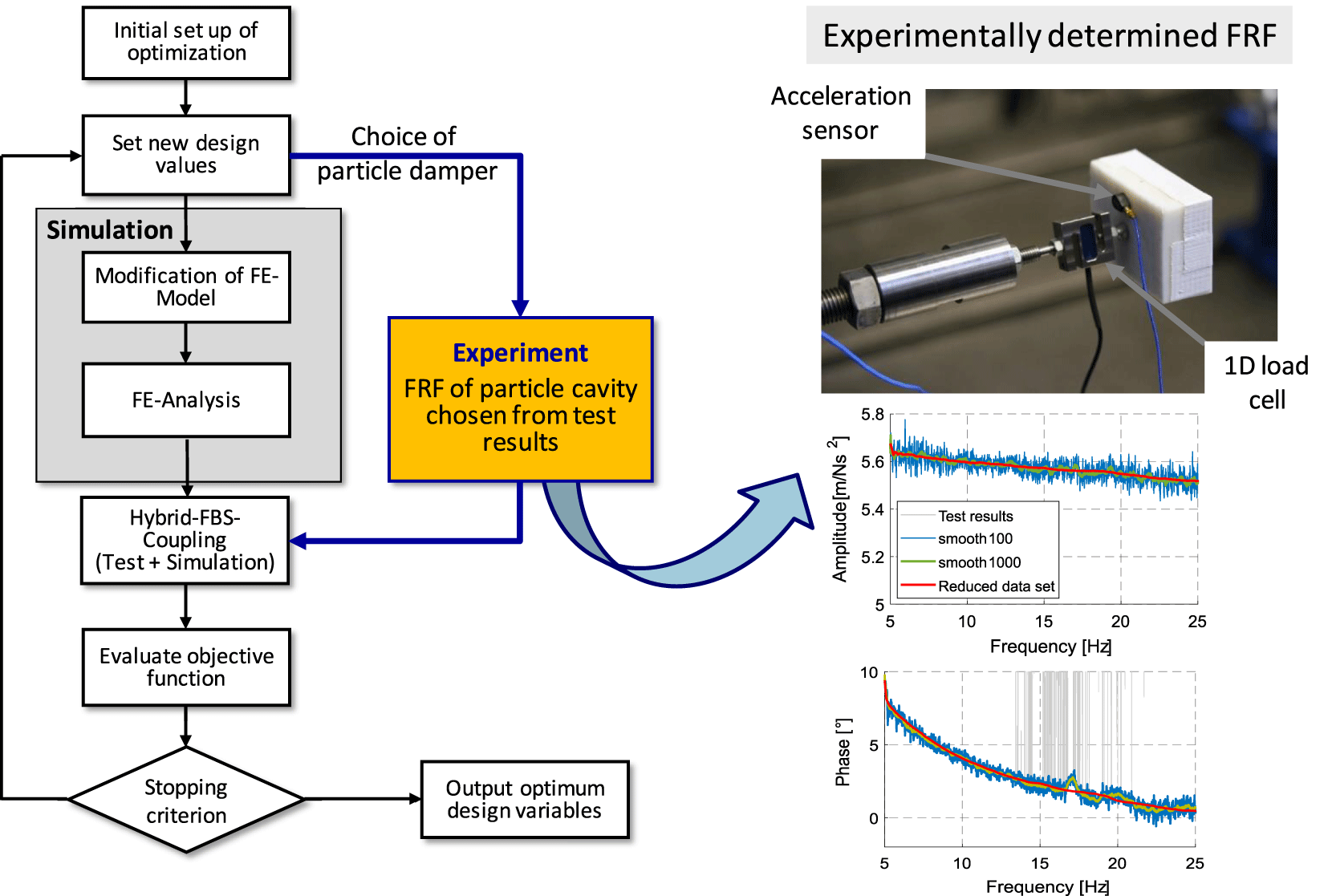
The FBS-optimization framework is shown in Figure 13. The single steps are explained in detail in the following. The FBS approach described in Section 3 is used for the coupled optimization of damping and weight for the honeycomb sandwich panel. To present the FBS-optimization, the introduced sandwich panel combined with the attached particle cavities (see Table 2) is used.
Optimization procedure for particle damping using frequency based substructuring.
The optimization is carried out with the genetic algorithm supplied by Matlab® since there is little knowledge regarding the objective function. Further, a deterministic solver, such as a gradient based optimization, is not chosen since no analytical gradient information can be calculated. This is due to the discontinuous, nondifferentiable objective function using the FBS approach. A finite difference approximation is inefficient as it requires many more calls of objective functions. Furthermore, with a generic algorithm, it is easier to find a global optimum for a function about which there is little knowledge and that cannot be differentiated in contrast to standard gradient based algorithms. The genetic algorithm selects so-called individuals as design values based on biological evolution via crossover methods and mutation of the current population and random numbers. Iterating over generations, the population approximates a numerically optimal solution.
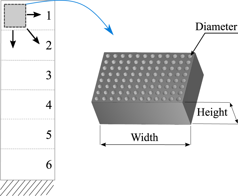
Design variables – The particle damping itself may increase the weight of the panel structure with respect to its best damping performance. Considering lightweight design and vibration comfort simultaneously, a compromise must be found. As it exhibits lightweight properties, the composite layer thickness  $t$ of the sandwich face sheets is chosen as a design variable for the weight optimization (Figure 14(a)). For the damping optimization, the choice of the size of particle cavity, the number of cavities, the position of the cavity and the filling ratio is used.
Constraints – Apart from the previous assumption acting as a constraint, the composite layer thickness is restricted with lower and upper bounds between 0.19 and 2 mm, as well as the position of the particle cavity, so as to avoid placements at the edge of the structure and overlapping of two or more cavities. For the latter, coupling is only allowed at defined nodes of the FE-model dependent on the size of the cavity.
Fitness function – As explained in Section 3, a genetic algorithm from Matlab was used. The investigation includes multiobjective optimization as well as the optimization of a scalar fitness (SF) function. The reason for this is that, for design purposes, a compromise between weight and vibration performance can more easily be argued with the help of a Pareto front when discussing more than one possible solution. An SF function, however, only leads to one numerically optimal solution. Both techniques are carried out and compared.
Design parameters for the optimization of the particle cavity and the composite layer thickness t (areas 1–6).
As multiobjective fitness (MF) values, the mass of the panel plus the PD and the maximum amplification  $\text{T}$ is calculated using the FBS approach. A two-dimensional Pareto front is therefore derived, enabling the best results to be chosen. The scalar optimization carried out uses the following SF function:
 $$\begin{eqnarray}SF=a\biggl(\frac{\text{m}_{\text{opt}}}{\text{m}_{\text{ref}}}\biggr)+b\biggl(\frac{\text{T}_{\text{opt}}}{\text{T}_{\text{ref}}}\biggr).\end{eqnarray}$$
 Here  $\text{T}_{\text{opt}}$ refers to the current maximum vibration amplitude of the transmissibility function from the bottom to the top of the panel with PD. In contrast, $\text{T}_{\text{ref}}$ is the reference maximum transmissibility from the sandwich panel without damping treatment (Figure 7). $\text{m}_{\text{opt}}$ and $\text{m}_{\text{ref}}$ refer to the total masses of the systems, respectively. $a$ and $b$ are the weighting factors for each term. The third objective function used is a simple mass minimization (MM) with a nonlinear constraint of the maximum amplification. The disadvantage here is that the amplification cannot be controlled. The advantage is that the MM is focused for lightweight design and a maximum tolerable amplification can be constrained, which facilitates the fitness evaluation. For each optimization run, a population of 40 individuals is set and, because of the stochastic nature of genetic algorithms, every optimization is carried out 5 times to increase the probability of finding a global optimum. The optimization results are presented in the following. For all fitness functions, the relative change of the best fitness value over 20 generations is used as the stopping criterion. If the relative change is smaller than 0.001, the optimizations stop.
3.2 Results
In Figure 15(a), the Pareto front of the optimization minimizing mass and amplifications is shown for two different lower thickness bounds (lb).  $\text{lb}_{2}=0.28~\text{mm}$ is a standard layer thickness available for the honeycomb sandwich in cabin interiors used for components without structural relevance. $\text{lb}_{1}=0.19~\text{mm}$ is the theoretically minimum thickness as the same prepreg layer thickness material is available on the market. Generally, there are two main Pareto solutions (MF1 and MF2; see Table 2) that allow a weight reduction in this simple vibration example. Both reduce the layer thickness to the minimum bound of 0.19 mm. The first, around an amplification of 35, is coupled with a small PD with a 25% filling ratio. The other result is also a small PD but with a 50% filling ratio. Experimental results from sandwich panels with 1 and 2 layers and no damping treatment are displayed in red as reference values. Design engineers have to decide which solution to choose. Therefore, in Figure 15(b), a weight specific damping $\unicode[STIX]{x1D6FF}^{\ast }$
 $$\begin{eqnarray}\unicode[STIX]{x1D6FF}^{\ast }=\frac{\text{T}_{\text{opt}}}{\text{ m}_{\text{opt}}}\end{eqnarray}$$
 is shown with the maximum amplification  $T$ (transmissibility) and the mass $m$ of the panel and the PD. Following these results, the PD with a 50% filling ratio should be chosen since the acquired amplitude reduction per weight is the best. However, different design constraints may lead to other decisions.
Results of genetic optimization for the composite layer, particle cavity and its position with a lower bound of lb = 0.19 mm

(a) Pareto optimal results of the multiobjective optimization. (b) Weight specific damping of Pareto results.

In considering the layer thickness, the two 1D scalar optimizations with SF and MM lead to similar results. It is close to 0.19 mm. With SF as fitness, a PD with a 50% filling ratio (SF1), and with MM as fitness, a 25% filling ratio is proposed (see Table 2). Due to the nature of the fitness functions, for MM, the lighter solutions are preferred and, with the combined fitness function SF dependent on the weighting factors (here, a = b = 1), different solutions can be more suitable. Therefore, functions can be chosen dependent on the design objective fitness.
To extend the optimization to the choice of more than one PD, the optimization was augmented with automatic meshing of RBE2 interfaces at the chosen coupling points. The mesh is set so as to have 10 distinct coupling points on the panel where PD can be applied. Thus, the optimization is carried out allowing one to choose the number of PDs. However, MF Pareto results, coupled with all or only one PD, as well as all other solutions are dominated by these two factors. This is similarly the case with MM results in the coupling of only one small PD. In the case of the optimization with the SF function, the attachment of two small PDs with a 50 % filling ratio is proposed (SF2). This suggests that the relation of the two terms in the fitness function (18) is chosen and weighted appropriately so as to allow a compromise between the lightest weight and the largest vibration reduction. A further optimization using SF with a constraint on the frequency shift (SF3) to be between 12 Hz and 16 Hz was carried out in order to show that different design solutions dependent on the constraints can be also achieved. This resulted in a design with increasing layer thickness from the top of the panel to the fixture at the bottom.
In Table 2, all numerical results are summarized including the optimized composite layer thickness  $t$ (see Figure 14). From the multiobjective optimizations, the two lighter alternatives are chosen in comparison to the two reference panels. All optimization runs are carried out constraining both lower bounds lb1 and lb2. Since they qualitatively revealed similar results, only the results for lb1 are shown.
Overall, lightweight potential for design of the panel is only realized by reducing the laminate thickness of the face sheets. The weight of a standard sandwich panel with two layers can be reduced from 709 g to less than 500 g in order to minimize vibrations. The assessment, with respect to the standard lay-up (537 g), also allows a minimal mass decrease to a theoretical minimum layer thickness. Furthermore, and more importantly, for the defined operating point, it is generally possible to find the minimum particle mass to be added for vibration suppression as well as to conduct a structural assessment of how much the weight can be reduced.
In Figure 16, the optimization results are compared to experimental data. First, it can be seen that simply increasing the laminate thickness from  $t=0.28~\text{mm}$ to 0.38 mm does not shift the resonance frequency out of range and, moreover, increases the weight by more than 50% (1 layer $\stackrel{\wedge }{=}238~\text{g}$). Furthermore, a test result with the fixed mass ( $=$ 400 grams) is shown to prove that there is only a slight influence on the damping properties due to the pure weight increase. Mainly, this only leads to a frequency shift.
Results of the genetic optimization.

The results of the optimization with the MF, SF and MM fitness functions demonstrate agreement with experimental tests. The test results are displayed with dashed lines and optimization results with continuous lines. The expected optimum solution at the top of the panel is confirmed for all results. The slight differences between the composite lay-ups in test and experiment do not play a large role such that the validation can, in this way, be taken as sufficient. The result of the two small PDs is compared to the test with one medium PD because moving from the small to medium PDs, the PD size is exactly doubled. The only difference is that with two small PDs, there are more particles near the top of the panel. This seems to reduce the amplification slightly more than with one medium PD. For all results, the differences for resonance frequency and amplification are within a 10% bound. The optimization using SF3 leads to the heaviest design. However, this shows that it is possible to reduce the weight and the amplification, while maintaining the stiffness of the panel at a higher level than that for the design solution for SF2.
3.3 Discussion of design approach
The application of the FBS within an optimization framework for particle damping and lightweight optimization is shown in a simple beam example. With the dynamic substructuring approach, the nonlinear particle behaviour due to inelastic impacts and friction itself is not modelled. Instead, experimental results of the uncoupled PD can be used for a hybrid FBS using simulation and experimental models for a full system analysis.
Compared to the state of the art, this approach offers certain advantages. First, the approach allows easier exploitation of the large design space and parameters for particle damping. Furthermore, a weight optimization of the damper as well as the primary structure can be considered based on the repetitive use of damper unit cells. The identification of modelling parameters for the particle damping itself is not necessary. Once identified, results can be reused for different structures. Smaller tests, on the PDs only, can be carried out and coupled to large full-scale structures in a bottom-up procedure.
However, there are still some drawbacks and limitations in order to successfully apply the approach presented. First of all, it is taken as given that, for the particle cavities, the damping behaviour can be approximated by the linear FBS approach and, within a defined point of operation, by the particle damper. The validity for the point of operation has to be determined before optimization, either from experimental tests or engineering experience.
For the example shown here, the variation of the filling ratio at higher excitation amplitudes above 0.35 g leads to nonlinear behaviour. This cannot be predicted by the FBS approach. However, the relative prediction error, with respect to the overall vibration reduction, is small. Moreover, the PD efficiency decreases if there is an increase in excitation for the honeycomb panel. The PD is less efficient relative to the amplification of the primary structure without PD because, at the same time, other damping effects (e.g., interface damping at the fixture) increase disproportionately. The current experimental evaluations show that, for lightweight structures where no strong mass increase is desirable, the approximation by the linear FBS approach can be remarkably accurate if the excitation levels are small. This can be attributed to the fact that the added particle mass is much smaller than the mass of the primary structure and does not produce strong changes in the dynamic behaviour. For larger and heavier structures, it is expected to be observably more realistic since the relative mass gain can be even smaller.
As a final requirement, for the PD design, there must be a certain number of particle systems available to choose from. This means necessary FRFs have to be derived in experimental tests in advance. However, the identified damper FRFs can be used for full-scale system predictions. In this way, only small tests and fewer large and expensive full-scale tests have to be carried out. Furthermore, with an increasing database of PDs, there may be a decrease in testing efforts due to the flexible coupling of unit cells to different structures.
4 Conclusion and outlook
Particle damping is a promising damping technology for the vibration reduction of lightweight structures. As a passive damping technology, it offers the possibility of increasing the damping capacity of a structure with only a small weight gain. Combined with the opportunity of adjusting structural parameters, such as the composite lay-up, there are further opportunities to compensate or even reduce the overall weight. In the dynamic domain, however, the structural design and the design of the damping properties are closely related and very sensitive to each other, especially if interface damping is included as necessary for a realistic design study.
Due to the difficulty in predicting damping parameters for particle damping, trial-and-error testing is still a common procedure for design optimization. In order to keep the number of large full-scale tests to a minimum and to exploit lightweight potential, a new approach to predict the particle damping for harmonic excitation using hybrid FBS is proposed. Due to the fast calculation time in the frequency domain and repetitive use of PD unit cells, damping and structural optimization become feasible simultaneously and thus enable fast design iterations in case the validity for the investigated point of operation is given.
In this paper, the design of PDs is demonstrated on a honeycomb panel with base point excitation. The reason for the choice of a simple beam system is to make the suggested optimization framework easy to understand and reproducible, as explained in Section 3. The design optimization was implemented with a genetic algorithm in order to automatically and quickly determine design possibilities. Different objective functions were used, and the results are discussed with respect to the multiobjective design goal. Compared to experimental tests, the results show good agreement at small excitation levels. With increasing excitation levels, the investigated system shows a very strong nonlinear behaviour, which cannot be predicted yet. However, a combined lightweight and damping optimization for particle damping may possibly allow the comparison of dampers and structural modifications.
The objective for further development is to apply and validate the proposed experimental and numerical optimization framework to components of an aircraft cabin and to enhance the framework towards higher driving frequencies as well as several mode shapes with different displacement amplitudes. PD-FRFs are intended to be evaluated at different excitation levels and coupled to the primary structure dependent on the excitation at the point of application.
Compared to other modelling approaches, the FBS approach can also serve as an addition for studies to find, for example, suitable materials or certain geometries for particle cavities in order to decrease the design space for further simulations. That is, if the computational effort of detailed models like DEM reaches an affordable limit.
Generally, designing damping technologies using the FBS approach can be a simple procedure. Here, with the help of a numerical and experimental method, a complex nonlinear problem can be managed and even applied to an optimization framework. In the future, this can be transferred to other damping technologies, and therefore methodical research should be intensified in order to make design processes for the development of industrial applications more efficient.


 Open access