





Introduction
Multi-way power dividers are key components in many microwave applications such as power and low-noise amplifiers as well as phased antenna arrays [Reference Kumar, Ali, Kumar, Kumar and Anguera1–Reference Kumar, Kumar, Ali, Kumar and Subhash3]. In recent years, there has been an increasing demand for low-cost, compact, and miniaturized power dividers for various microwave and mm-wave applications. For this purpose, Wilkinson-type [Reference Choe and Jeong4] and Gysel-type dividers [Reference Wu, Wu, Yang, Wang and Kishk5] are widely used. Generally, an n-way Wilkinson divider is nonplanar for n ≥ 3 because the 3D floating common node makes its planar implementation difficult. Although several planar structures have been proposed, they are rather complicated since they employ multi-section lines [Reference Zhou, Morris and Lancaster6], p-i-n diodes [Reference Fan, Liang, Geng, Liu and Jin7], a multilayer structure [Reference Abbosh8], and coupled lines [Reference Chiu, Lin and Wang9, Reference Kim, Jeon and Jeong10]. Miniaturized planar structures have also been proposed, but they are also complicated because they either employ cascaded Lange couplers [Reference Hayashi11] or multi-section lines [Reference Zhang, Che and Chen12]. Recently, high-isolation planar dividers based on a recombinant structure and multi-section impedance transformers have been presented [Reference Abdullah, Farooq, Zakir and Cheema13, Reference Abdullah, Zakir and Cheema14]. In [Reference Tsitsos, Anastassiu and Papatsoris15], a very simple wideband planar structure with good return loss and isolation characteristics was proposed. However, this structure was analyzed using only λ/4 lines, resulting in a 3λ/4-long structure. More recent planar structures have been reported, but they are rather complicated since they employ composite right- and left-handed transmission lines with lumped capacitors [Reference Song, Zhao, Chen and Patience16] or provide only two-way power division [Reference Tadayon, Ardakani, Karimian, Ahmadi and Zaghloul17].
In this work, we extend the work presented in [Reference Tsitsos, Anastassiu and Papatsoris15] by investigating the design of a simple, wideband, and compact planar power divider with an arbitrary line length. It is demonstrated that the proposed structure can sufficiently operate using λ/8 lines, resulting in an overall length of 3λ/8, which is half of that reported in [Reference Tsitsos, Anastassiu and Papatsoris15]. The proposed design achieves a wideband operation (1.6–3.3 GHz) and can be expanded to an n-way structure. It also uses practical characteristic impedance values (thus providing easy implementation) and offers design flexibility. The proposed planar divider is first theoretically analyzed using transmission line theory and then fabricated on a microstrip substrate. Finally, experimental measurements are performed to validate the theoretically predicted results.
Circuit analysis
The proposed three-way planar power divider is presented in Fig. 1. It features a main block (shown as BLOCK), which consists of three transmission lines (each with characteristic impedance Z 1). All lines have an arbitrary electrical length θ (0° ≤ θ ≤ 90°) at the midpoint frequency of operation. The divider also employs two isolation resistors (each with value R) placed between ports 2 and 3 and between ports 3 and 4, respectively.
The proposed three-way wideband planar power divider employing transmission lines of arbitrary length θ.
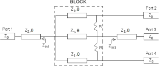
The extra transmission lines with characteristic impedances Z 2 and Z 3 and length θ at the input (port 1) and output (port 3), respectively, achieve the wideband characteristics of the proposed power divider. In this work, we set θ = 45° to achieve a compact design. If we increase θ το 90°, the bandwidth will be increased but not significantly. However, this increase in θ leads to an increase in the total length of the divider, as reported in [Reference Tsitsos, Anastassiu and Papatsoris15]. On the other hand, if we make θ < 45° to achieve a more compact design, the bandwidth will be decreased to some extent and the lines will become very short, leading to coupling effects and difficulties in implementation.
Equal power splitting is achieved by employing transmission lines with the same characteristic impedance Z 1 inside the BLOCK (Fig. 1). The input and output lines with characteristic impedances Z 2 and Z 3, respectively, also achieve impedance matching. The derived equations for the input impedances Z inC and Z′inC (see Fig. 1) are set equal to Z 0 and Z in3, respectively, by imposing the matching condition at ports 2 and 3, as shown in equations (9) and (16).
The input impedances Z in1 and Z in3 are given as follows:
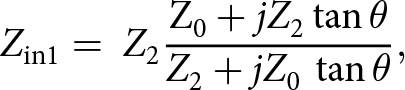 \begin{equation}{Z_{\rm{in1}}} = {\ }{Z_2}{{{{\rm Z}_0} + j{Z_2}\tan {{\theta }}} \over {{Z_2} + j{Z_0}\,\tan {{\theta }}}},\end{equation}
 \begin{equation}{Z_{{\rm{in}}3}} = {Z_3}{{{Z_0} + j{Z_3}\,\tan \theta } \over {{Z_3} + j{Z_0}\,\tan \theta }}.\end{equation}
Considering the components contained in the BLOCK (see Fig. 1), we initially apply a voltage source to port 2. Assuming ideal isolation at the remaining output ports, the voltages at ports 3 and 4 must be zero (i.e., V 3 = V 4 = 0). Therefore, from the BLOCK shown in Fig. 1, the circuit shown in Fig. 2 can be derived.
The circuit derived from the BLOCK (shown in Figure 1) by applying a voltage at port 2.
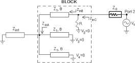
Based on Fig. 2, Z inA can be calculated as follows:
 \begin{equation*}{1 \over {{Z_{{\rm{in}}A}}}} = {1 \over {{Z_{{\rm{in}}1}}}} + {1 \over {j{Z_1}\,\tan \theta }} + {1 \over {j{Z_1}\,\tan \theta }},\end{equation*}
which results in the following equation:
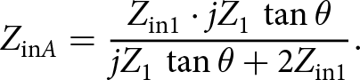 \begin{equation}{Z_{{\rm{in}}A}} = {{{Z_{{\rm{in}}1}} \cdot j{Z_1}\,\tan \theta } \over {j{Z_1}\,\tan \theta + 2{Z_{{\rm{in1}}}}}}.\end{equation}
In equation (3), by substituting Z in1 from equation (1), the following equation can be obtained:
 \begin{equation}{Z_{{\rm{in}}A}} = {{j{Z_0}{Z_1}{Z_2}\,\tan \theta - {Z_{\rm{1}}}{Z_2}^2\,{\rm{ta}}{{\rm{n}}^{\rm{2}}}\theta } \over {j{Z_1}{Z_2}\,\tan \theta - {Z_{\rm{0}}}{Z_1}\,{{\tan }^2}\theta + 2{Z_0}{Z_2} + j2{Z_2}^2\,\tan \theta }}.\end{equation}
Also, based on Fig. 2, the input impedance Z inB can be written as follows:
 \begin{equation}{Z_{{\rm{in}}B}} = {Z_1}{{{Z_{{\rm{in}}A}} + j{Z_1}\,\tan \theta } \over {{Z_1} + j{Z_{{\rm{in}}A}}\,\tan \theta }}.\end{equation}
In equation (5), by substituting Z inA from equation (4), the following equation can be obtained:
 \begin{equation}{Z_{{\rm{in}}B}} = {{j{Z_{{\rm{in}}1}}{Z_1}\,\tan \theta - {Z_1}^2\,{{\tan }^2}\theta + j2{Z_1}{Z_{{\rm{in}}1}}\,\tan \theta } \over {j{Z_1}\,\tan \theta + 2{Z_{{\rm{in1}}}} - {Z_{{\rm{in}}1}}\,{{\tan }^2}\theta }}.\end{equation}
Furthermore, based on Fig. 2, the input impedance Z inC can be written as follows:
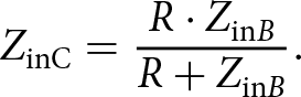 \begin{equation}{Z_{{\textrm{inC}}}} = {{R \cdot {Z_{{\textrm{in}}B}}} \over {R + {Z_{{\textrm{in}}B}}}}.\end{equation}
In equation (7), by substituting Z inB from equation (6), the following equation can be obtained:
 \begin{equation}{Z_{inC}} = {{R\left[ {j3{Z_1}{Z_2}\tan \theta \cdot {{{Z_0} + j{Z_2}\tan {{\theta }}} \over {{{Z}_2} + j{Z_0}\tan {{\theta }}}} - {Z}_{\textrm{1}}^{\textrm{2}}\ {{\tan }^2}\theta } \right]{\ }} \over {\begin{array}{c} R\left[ {j{Z_1}\tan {{\theta }} + {{\text{Z}}_{\textrm{2}}}{{{Z_0} + j{Z_2}\tan \theta } \over {{{\textrm Z}_2} + j{Z_0}\tan {{\theta }}}} \cdot (2 - {{\tan }^2}{{\theta )}}} \right] \\ + \left[ {j3{Z_1}{Z_2}\tan {{\theta }}{{{Z_0} + j{Z_2}\tan {{\theta }}} \over {{Z_2} + j{Z_0}\tan {{\theta }}}} - {Z}_1^2{\ {\tan }^2}\theta } \right]\end{array}}}.\end{equation}
The above equation can also be derived if a voltage source is applied to port 4 because the divider of Fig. 1 is symmetric along its central axis.
The matching condition at port 2 requires
 \begin{equation}{Z_{{\textrm{in}}C}} = {Z_0}.\end{equation}
Next, we apply a voltage source to port 3. Assuming ideal isolation at the remaining output ports, the voltages at ports 2 and 4 must be zero (i.e., V 2 = V 4 = 0). Therefore, from the BLOCK shown in Fig. 1, the circuit shown in Fig. 3 can be derived.
Circuit derived from the BLOCK (shown in Figure 1) when applying a voltage at port 3.

Based on Fig. 3, Z′ inA can be calculated as follows:
 \begin{equation*}{1 \over {{{Z'}_{{\rm{in}}A}}}} = {1 \over {{Z_{{\rm{in}}1}}}} + {1 \over {j{Z_1}\,\tan \theta }} + {1 \over {j{Z_1}\,\tan \theta }},\end{equation*}
which results in the following equation:
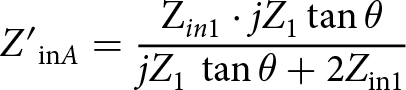 \begin{equation}{{{Z'}_{{\rm{in}}A}}} = {{{{\rm Z}_{in1}} \cdot j{Z_1}\tan {{\theta }}} \over {j{Z_1}\,\tan {{\theta }} + {\rm{2}}{{{{Z}}}_{{\rm{in1}}}}}}\end{equation}
In equation (10), by substituting Z in1 from equation (1), the following equation can be obtained:
 \begin{equation}{Z'_{{\rm{in}}A}} = {{j{Z_1}{Z_2}\,\tan \theta \cdot \left( {{Z_0} + j{Z_2}\,\tan \theta } \right)} \over {j{Z_1}\,\tan \theta \cdot \left( {{Z_2} + j{Z_0}\,\tan \theta } \right) + 2{Z_2} \cdot \left( {{Z_0} + j{Z_2}\,\tan \theta } \right)}}.\end{equation}
Also, based on Fig. 3, the input impedance Z′ inB can be written as follows:
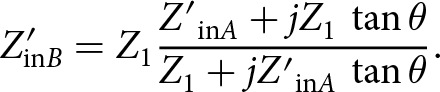 \begin{equation}{Z'_{{\rm{in}}B}} = {Z_1}{{{{Z'}_{{\rm{in}}A}} + j{Z_1}\,\tan \theta } \over {{Z_1} + j{{Z'}_{{\rm{in}}A}}\,\tan \theta }}.\end{equation}
In equation (12), by substituting Z′ inA from equation (10), the following equation can be obtained:
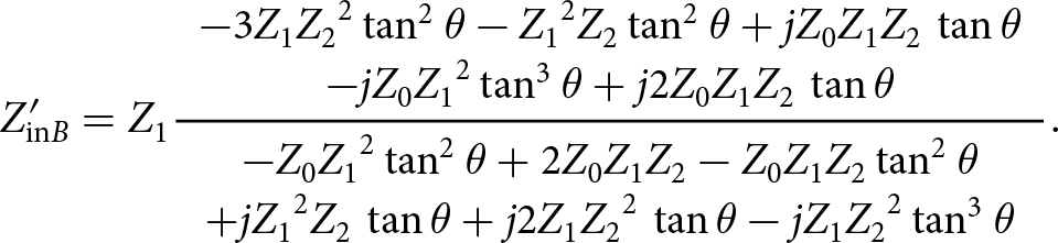 \begin{equation}{Z'_{{\rm{in}}B}} = {Z_1}{{{\begin{array}{c} - 3{Z_1}{Z_2}^2\,{{\tan }^2}\ \theta - {Z_1}^2{Z_2}\,{{\tan }^2}\ \theta + j{Z_0}{Z_1}{Z_2}\,\tan \theta \\ - j{Z_0}{Z_1}^2\,{{\tan }^3}\ \theta + j2{Z_0}{Z_1}{Z_2}\,\tan \theta \end{array}}} \over {{\begin{array}{c} - {Z_0}{Z_1}^2\,{{\tan }^2}\ \theta + 2{Z_0}{Z_1}{Z_2} - {Z_0}{Z_1}{Z_2}\,{{\tan }^2}\ \theta \\ + j{Z_1}^2{Z_2}\,\tan \theta + j2{Z_1}{Z_2}^2\,\tan \theta - j{Z_1}{Z_2}^2\,{{\tan }^3}\ \theta \end{array}}}}.\end{equation}
Furthermore, based on Fig. 3, the input impedance Z′ inC can be written as follows:
 \begin{equation}{Z'_{{\textrm{in}}C}} = {{R{{Z'}_{{\textrm{in}}B}}} \over {R + 2{{Z'}_{{\textrm{in}}B}}}}.\end{equation}
In equation (14), by substituting Z′ inB from equation (12), the following equation can be obtained:
 \begin{align} {{Z{^{\prime}}}_{{\rm{in}}C}} & = {{\begin{array}{c}R{Z_1}\left( - 3{Z_1}{Z_2}^2\,{{\tan }^2}\ \theta - {Z_1}^2{Z_2}\,{{\tan }^2}\ \theta + j{Z_0}{Z_1}{Z_2}\,\tan \theta \right.\\ \left. - j{Z_0}{Z_1}^2\,{{\tan }^3}\ \theta + j2{Z_0}{Z_1}{Z_2}\,\tan \theta \right)\end{array}} \over {\begin{array}{c} R\left( - {Z_0}{Z_1}^2\,{{\tan }^2}\ \theta + 2{Z_0}{Z_1}{Z_2} - {Z_0}{Z_1}{Z_2}\,{{\tan }^2}\ \theta \right.\\ \left.+ j{Z_1}^2{Z_2}\,\tan \theta + j2{Z_1}{Z_2}^2\,\tan \theta - j{Z_1}{Z_2}^2\,{{\tan }^3}\ \theta \right)\end{array}}} \\ &\qquad+ 2{Z_1}\left( - 3{Z_1}{Z_2}^2\,{{\tan }^2}\ \theta - {Z_1}^2{Z_2}\,{{\tan }^2}\ \theta + j{Z_0}{Z_1}{Z_2}\,\tan \theta \right.\\ &\qquad\quad\left.- j{Z_0}{Z_1}^2\,{{\tan }^3}\ \theta + j2{Z_0}{Z_1}{Z_2}\,\tan \theta \right). \end{align}
The matching condition at port 2 requires
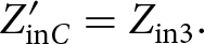 \begin{equation}{Z'_{{\textrm{in}}C}} = {Z_{{\textrm{in}}3}}.\end{equation}
Implementation, results, and discussion
Equations (8), (9) and (15), (16) can be used as the design equations of the proposed power divider. These equations are satisfied for a number of solutions. Thus, the variety of parameter values provides design flexibility. To achieve a compact design, θ = 45° was selected at a midpoint frequency of 3 GHz. Also, by selecting Z 0 = 50 Ohm, R = 100 Ohm, and Z 1 = 90 Ohm, equations (8), (9) and (15), (16) yield practically realizable impedance values (Z 2 = 23.23 Ohm and Z 3 = 47.91 Ohm). These parameter values are summarized in Table 1.
Electrical parameter values for the proposed power divider in Figure 1

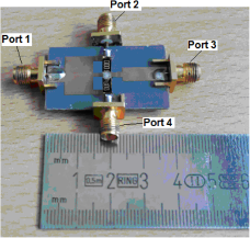
The proposed three-way wideband planar power divider shown in Fig. 1 was fabricated on a printed circuit board (PCB) using a TACONIC substrate with a typical dielectric constant of 2.2 (Fig. 4). The layout of the proposed power divider was produced using the Advanced Design System simulation software. Then, we placed a mask of the layout on the top copper surface of the TACONIC substrate and immersed it into a solution of sodium hydroxide to remove the unwanted copper. Thus, the upper conductors of the microstrip lines with the desired dimensions were fabricated. Commercial 100-Ohm resistors were used to achieve the necessary isolation between the output ports. These resistors could, in principle, cause some parasitic effects. However, in the operating frequency range of the divider, these effects are negligible. We employed an Agilent E5071C vector network analyzer to measure the scattering parameters (amplitude and phase) of the fabricated PCB over the frequency range 1–5 GHz. Before conducting measurements, we performed the standard transmission–line–through calibration procedure. The graphs in Fig. 5 show the simulated and experimental responses of the proposed divider. Good agreement can be observed. The discrepancies are mainly due to the limited accuracy of the etching process and the effect of the connectors, which were not included in the simulation. Due to our limited lab resources, we could not perform any calibration or correction procedures to address the discrepancies caused by the etching process and connectors during the measurement process. It is evident that in the frequency range 1.6–3.3 GHz (a fractional bandwidth of  ${{3.3 - 1.6} \over {2.45}} \cong $ 69.4%), the proposed divider achieves equal power split (∼32%, −4.9 ± 0.4 dB insertion loss) between the input and each output port and good matching and isolation characteristics. The measured return loss is better than −10 dB at all ports, and the measured maximum isolation is close to −30 dB. The maximum measured amplitude imbalance is ∼0.8 dB. The maximum measured phase imbalance between ports 2 and 4 is ∼8 degrees, whereas that between ports 2 and 3 (or 4 and 3) is ∼51 degrees. This is due to the extra length θ of the line with characteristic impedance Z 3 shown in Fig. 1.
Fabricated PCB of the proposed power divider.
Measured results for (a) input return loss, (b) output return loss, (c) insertion loss, (d) port isolation, (e) amplitude imbalance, and (f) phase imbalance of the proposed three-way planar divider shown in Figure 1

Generally, the phase imbalances measured are not significant in applications requiring an accurate splitting ratio. However, the phase imbalances measured between certain ports, although acceptable, may have an impact in phase array applications. In cases requiring very small phase imbalances, an appropriate phase shifter could be used.
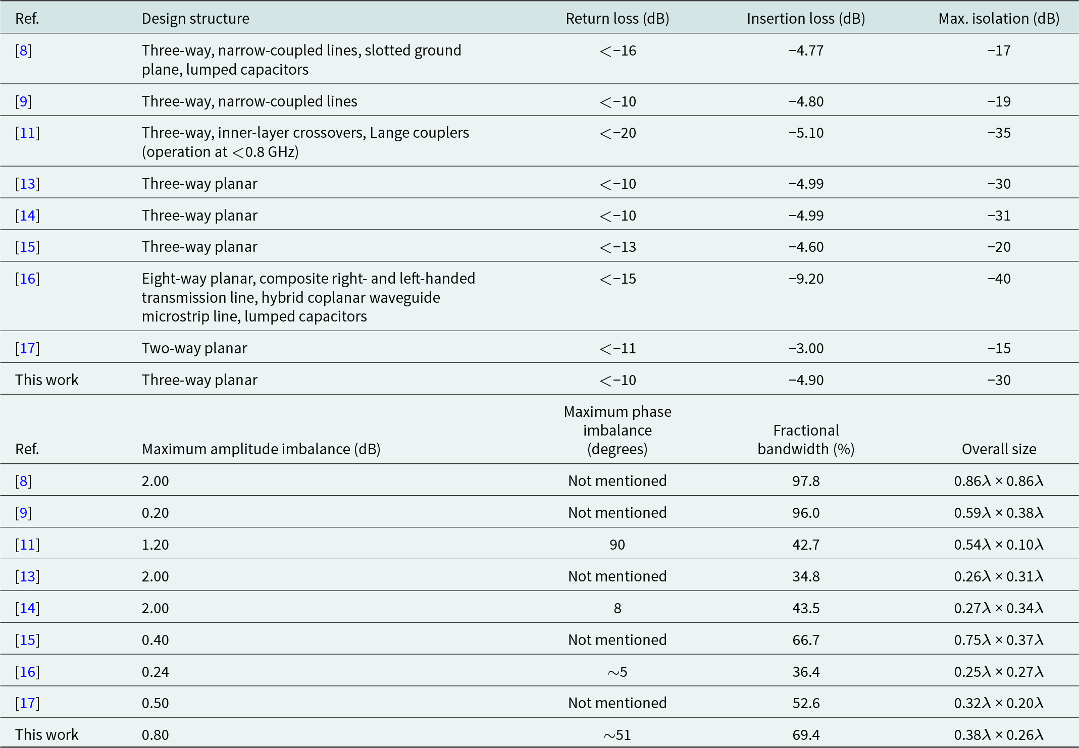
A performance comparison of the proposed planar power divider with the performance of previously published designs is shown in Table 2. It is evident that the performance of the proposed design is better than the performance of most other designs in terms of insertion loss, isolation, bandwidth, and size but falls short in terms of return loss. However, its design flexibility, easy implementation, and expansion to an n-way structure make it an attractive proposition.
Performance comparison of the proposed structure with the performance of previously published works
Conclusion
In this work, a planar three-way wideband power divider that avoids the floating common node of the isolation resistors was designed, simulated, fabricated, and tested. The mathematical analysis and extraction of design equations were based on the transmission line theory. The divider was fabricated on a microstrip substrate. Measured results showed a good agreement with the predicted data. It was also demonstrated that despite its very simple noncomplicated structure, the proposed design achieves similar performance and size compared with other more complicated structures. Furthermore, it provides design flexibility, can be easily implemented, and can be expanded to an n-way structure.
Competing interests
The authors declare no conflict of interests.

Stelios Tsitsos was born in Greece. He was awarded the Diploma in Electrical and Computer Engineering from the Democritus University of Thrace, Greece, and the M.Sc. in Communication Engineering and Digital Electronics from the Department of Electrical and Electronics Engineering, UMIST, UK. He was also awarded the Ph.D. Degree in Microwave Engineering from the same Department, where he also worked as a Research Assistant and then as a Research Associate. Afterwards, he joined the Greek Telecoms Organisation as a Senior Telecommunications Engineer. He is currently a Professor in the Department of Information, Computer and Telecommunications Engineering, International Hellenic University, Serres Campus, Greece. His research interests include the design and characterization of microwave components and sub-systems for various telecommunication applications.

Ioannis Giannenas was born in Greece. He was awarded the B.Sc. Degree in Information and Communications Engineering from Epirus Technological and Educational Institute, Greece, and the M.Sc. in Telecommunications from the Department of Information, Computer and Telecommunications Engineering, International Hellenic University, Serres Campus, Greece. He is currently teaching courses in Informatics and Communications to high-school students in Greece.


 Open access

