


1. Introduction
As an essential component of radar antenna, the antenna pedestal is a crucial infrastructure to bear static, dynamic and vibration loads. Traditional antenna pedestal is mainly in series structure, often with bulky structure, severe joint error accumulation and high power consumption [Reference Xu, Xue and Duan1, Reference Shufei, Duan and Duan2]. The parallel mechanism consists of two or more moving chains connected to the end-effector. It has good mechanical and structural performance when considering acceleration, accuracy, stiffness and the ability to carry heavy loads. In recent years, parallel mechanisms have been widely used in different fields, such as motion simulation, high-precision docking, MEMS mechanisms and active vibration isolation systems, and more and more scholars have applied parallel robots to antenna pedestals, such as the 500 m aperture spherical radio telescope FAST in Guizhou, China [Reference Duan, Mi and Zhao3] and the AMiBA radio telescope in Hawaii, USA [Reference Koch, Kesteven, Nishioka, Jiang, Lin, Umetsu, Huang, Raffin, Chen, Ibañez-Romano, Chereau, Huang, Chen, Ho, Pausch, Willmeroth, Altamirano, Chang, Chang, Chang, Han, Kubo, Li, Liao, Liu, Martin-Cocher, Oshiro, Wang, Wei, Wu, Birkinshaw, Chiueh, Lancaster, Lo, Martin, Molnar, Patt and Romeo4].
The antenna pedestal control system is a multi-variable complex system, which has been used to track electromagnetic signals. The signal strength mainly depends on the real-time position of the antenna, but the position changes continuously due to some interference [Reference Ahlawat, Prasad M.P. and Chauhan5]. Consequently, researchers have designed a series of controllers for tackling with the problem. Romsai uses the LFICus algorithm to tune the parameters of PID position controller of antenna pedestal, compared with PID controller with Ziegler-Nichols tuning, ROMSAI has better control effect [Reference Romsai, Nawikavatan, Lurang and Puangdownreong6]. Nupoor uses PID and LQG control algorithms to analyze the performance of the antenna position control system [Reference Patil and Behere7], and Ahlawat designs the controller based on MPC algorithm [Reference Ahlawat, Prasad M.P. and Chauhan5]. Hancioglu uses the FLC controller to control the antenna azimuth movement, and compared with PID controller, the control effect has improved. The FLC controller is designed based on experience without optimization [Reference Okumus, Sahin and Akyazi8]. According to the above papers, the controller based on modern control theory and intelligent control is often better than the traditional PID control effect for the current antenna seat control.
In this paper, a parallel robotic antenna pedestal is presented. The active joints of the mechanism are two servo-driven sliders on a static circular track. The synchronous and asynchronous motions of the two sliders result in azimuth and pitch rotation of the rotatable platform carrying the antenna, respectively [Reference Xue9]. This antenna pedestal control system is a multi-input, multi-output nonlinear system. The traditional PID control algorithm can no longer meet the control requirements of this kind of parallel mechanism. Therefore, researchers try to improve the actual control effect by changing the structure and parameters. Based on the essential idea of the fuzzy neural network algorithm, the functional relationship between the control error and the approach degree is established by Wang. Combining with the feedforward control algorithm, the adaptive adjustment of PID parameters is realized and the accuracy of the tracking algorithm is improved [Reference Wang, Zhu, Qi, Zheng and Li10]. For a novel Stewart-type offshore parallel antenna pedestal, he adopts a mobile sliding membrane control method to realize trajectory tracking [Reference He, Wu and Li11]. Al-Mayyahi proposed the FOPID controller for trajectory tracking of a 3-RRR planer parallel robot [Reference Al-Mayyahi, Aldair and Chatwin12]. Shang applied a new robust nonlinear controller to a 2-dof (degree-of-freedom) parallel mechanism [Reference Shang and Cong13]. Lu proposed a fuzzy logic controller and tuning procedure for tracking control of delta parallel robot [Reference Lu, Liu and Liu14]. Fuzzy control for nonlinear factors can significantly improve the control quality [Reference Shuang and Xianrong15]. It does not require an exact mathematical model and can be used for systems with delay and nonlinearity, as well as making the design process simpler and obtaining good robustness. In practice, it is more likely to handle uncertain disturbances. However, the traditional fuzzy controller cannot get satisfactory results, such as the existence of steady-state errors. Therefore, combining fuzzy controller with PI controller is one of the effective methods [Reference Wen, Zheng, Jia, Ji, Hao and Lam16].
The remaining of this paper is organized as follows. The structure of the parallel robotic antenna pedestal is described in Section 2. And in Section 3, the kinematic model is established. In Section 4, a fuzzy PI control system (FPI) is designed for closed-loop control of the position of the driving slider. A parameter coding method of fuzzy controller is introduced and improved. In Section 5, the parameters of the FPI controller are adjusted by the performance index of the integral of the time-weighted absolute value of the error (ITAE) to achieve the trajectory tracking of the specified position of the antenna. The Simulink simulation model is used for trajectory tracking experiments to verify the advantages over the traditional PI control. And the parallel robotic antenna pedestal prototype is introduced, and the algorithm is verified by experiments. Some meaningful conclusions are drawn in Section 6.
2. System description of the parallel robotic antenna pedestal
As shown in Fig. 1, the 2-dof parallel robotic antenna pedestal structure includes a rotatable platform (7), which is connected to the intermediate column (8) through a rotating pair (5). There is a revolute joint between the intermediate column and the base for turnover movement. Two symmetrically arranged rods (6) are connected to the platform through a Hook hinge (4) at the upper end, and the lower end of the rod is connected to the drive slider (2) through a 3-dof composite ball hinge (3). The drive slider engages with the circular track (1) of the antenna base through the gear pair.
Schematic of 2-dof parallel robotic antenna pedestal.
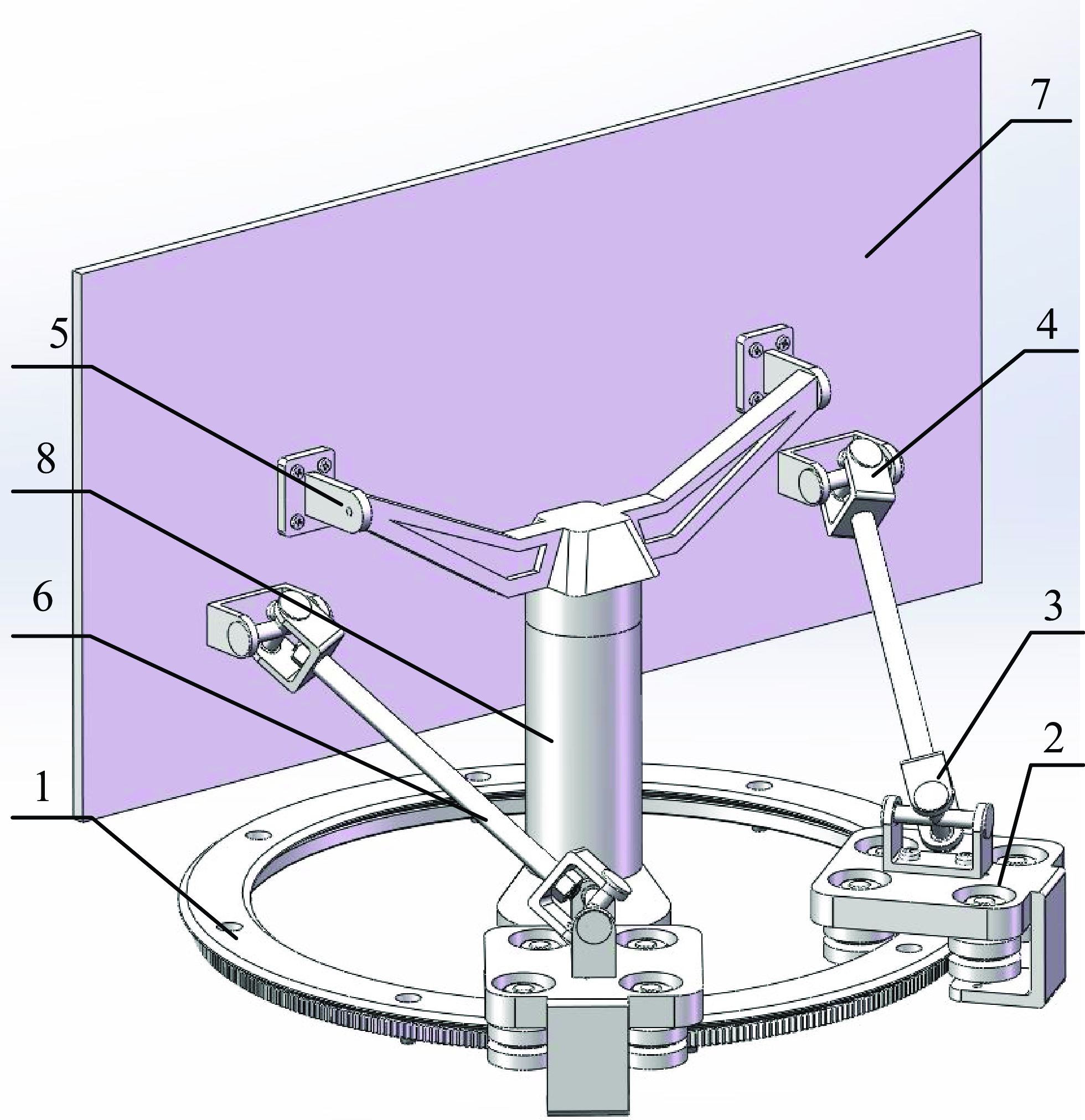
When the two drive sliders move in the same direction, the platform performs azimuthal motion, and when the sliders move in the opposite direction, the platform performs pitching motion. The composite motion of the azimuth and pitch of the antenna platform is realized by controlling the direction and speed of the two drive sliders according to its kinematic model.
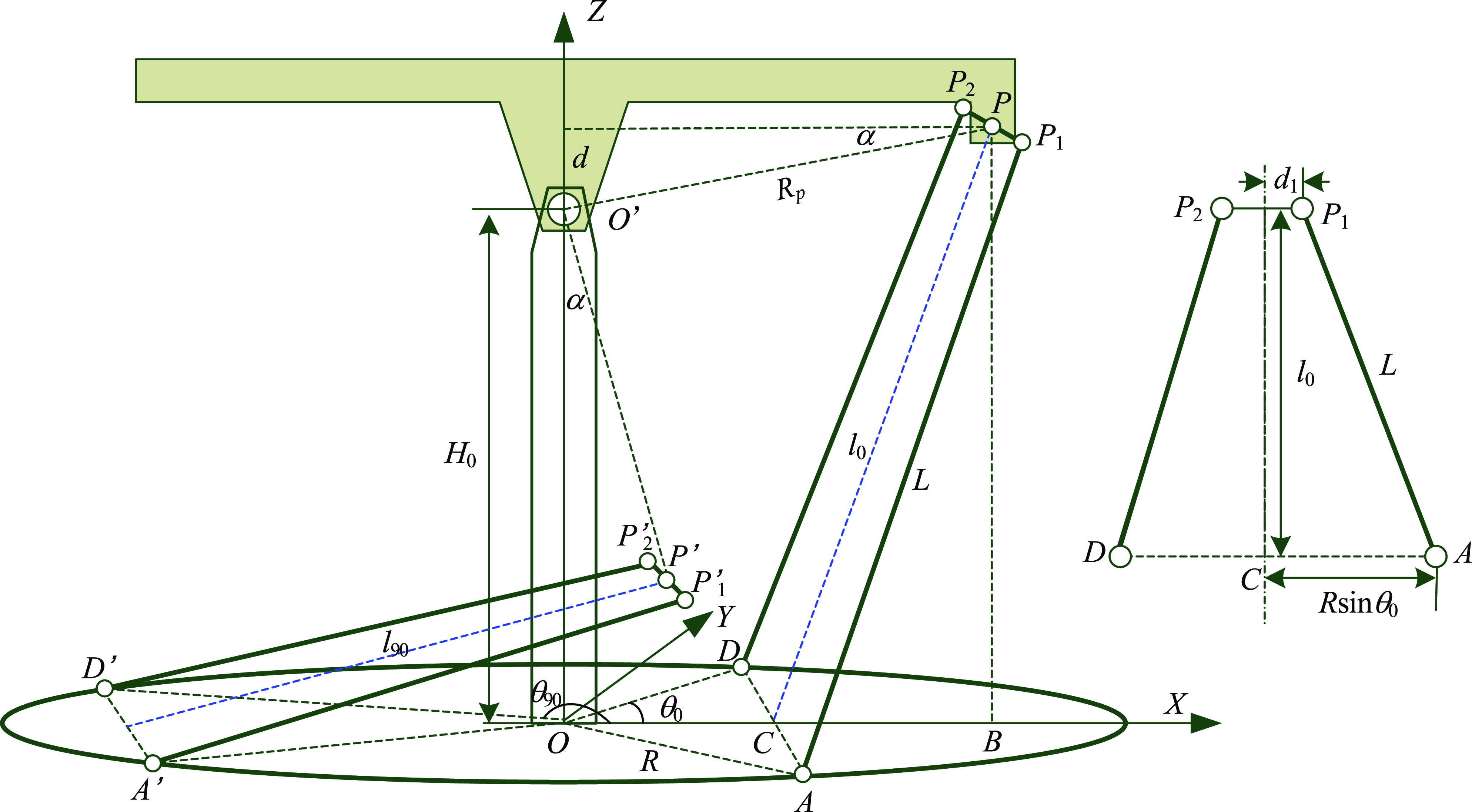
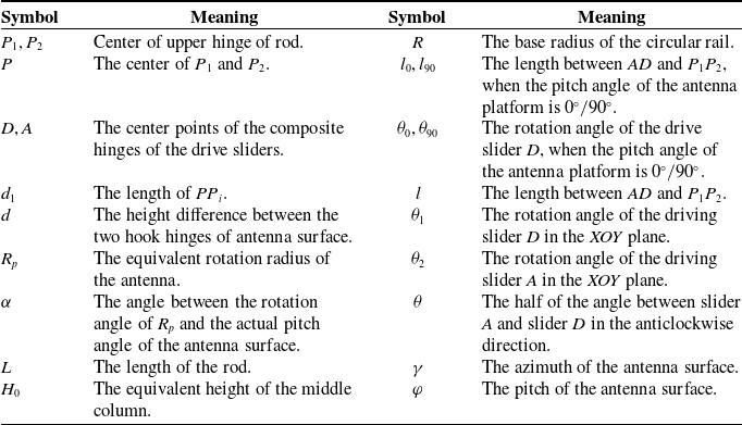
The sketch of the antenna pedestal mechanism is shown in Fig. 2. For ease of understanding and reading, the nomenclature list of the antenna pedestal (Table I) is added to the paper. The fixed coordinate system is established with the antenna pedestal orbit plane XOY. The length of the rods $P_{1}A$
and
$P_{1}A$
and $P_{2}D$
is L, and the base radius is R. The center points of the composite hinges of the drive sliders are A and D, respectively. The height between the axis
$P_{2}D$
is L, and the base radius is R. The center points of the composite hinges of the drive sliders are A and D, respectively. The height between the axis $P_{1}P_{2}$
and the coupling axis of the middle column is d.
$P_{1}P_{2}$
and the coupling axis of the middle column is d.
Sketch of the antenna pedestal mechanism.
Nomenclature list of the antenna pedestal.
Assume that the azimuth and pitch angle of the antenna shown in Fig. 2 is $0^{\circ }$
, and the azimuth angle of both the hinge center points A and D is
$0^{\circ }$
, and the azimuth angle of both the hinge center points A and D is $\theta _{0}$
. According to the trilateral relationship, one can conclude that
$\theta _{0}$
. According to the trilateral relationship, one can conclude that $AC=R\sin \theta _{0}$
, and then, the isosceles trapezoid P
1
P
2
DA satisfies the following constraint during the antenna motion.
$AC=R\sin \theta _{0}$
, and then, the isosceles trapezoid P
1
P
2
DA satisfies the following constraint during the antenna motion.
 \begin{equation} L^{2}=\left(R\sin \theta _{0}-d_{1}\right)^{2}+{l_{0}}^{2} \end{equation}
where L is the length of the rod, d
1 is half the length of $P_{1}P_{2}$
, and l
0 is the length between the lines AD and
$P_{1}P_{2}$
, and l
0 is the length between the lines AD and $P_{1}P_{2}$
when the azimuth and pitch angle of the antenna is
$P_{1}P_{2}$
when the azimuth and pitch angle of the antenna is $0^{\circ }$
.
$0^{\circ }$
.
As shown in Fig. 2, the height of the midpoint of $P_{1}P_{2}$
from the XOY plane is
$P_{1}P_{2}$
from the XOY plane is $H_{0}+d$
, and the distance of the point from the Z axis is
$H_{0}+d$
, and the distance of the point from the Z axis is $R_{P}\cos \alpha$
. The x coordinate value of point C is
$R_{P}\cos \alpha$
. The x coordinate value of point C is $R\cos \theta _{0}$
. Under the condition that the pitch angle of the platform takes
$R\cos \theta _{0}$
. Under the condition that the pitch angle of the platform takes $0^{\circ }$
and
$0^{\circ }$
and $90^{\circ }$
, respectively, the relationship between
$90^{\circ }$
, respectively, the relationship between $l_{0},l_{90},\theta _{0}$
and
$l_{0},l_{90},\theta _{0}$
and $\theta _{90}$
is as follows.
$\theta _{90}$
is as follows.
 \begin{equation} l_{0}^{2}=\left(H_{0}+d\right)^{2}+\left(R_{P}\cos \alpha -R\cos \theta _{0}\right)^{2} \end{equation}
 \begin{equation} l_{90}^{2}=\left(H_{0}-R_{P}\cos \alpha \right)^{2}+\left(d+R\cos \theta _{90}\right)^{2} \end{equation}
where $\alpha =\arcsin (d/R_{p})$
, d is the height difference between the two Hook hinges,
$\alpha =\arcsin (d/R_{p})$
, d is the height difference between the two Hook hinges, $R_{P}$
is the equivalent rotation radius of the antenna surface, and H
0 indicates the equivalent height of the middle column.
$R_{P}$
is the equivalent rotation radius of the antenna surface, and H
0 indicates the equivalent height of the middle column.
Substituting Eqs. (2) and (3) into Eq. (1), the radius of the circular rail R is calculated as follows [Reference Ahlawat, Prasad M.P. and Chauhan5].
 \begin{equation} R=\frac{H_{0}\!\left(R_{P}\cos \alpha +d\right)}{d_{1}\!\left(\sin \theta _{0}-\sin \theta _{90}\right)+d\cos \theta _{90}+R_{p}\cos \alpha \cos \theta _{0}} \end{equation}
3. Kinematic model
In order to accurately control the attitude of the antenna pedestal, it is necessary to analyze the positional relationship of the 2-dof parallel robotic antenna pedestal, that is, to solve the relationship between the antenna pedestal platform attitude and the motion of the drive sliders, including inverse and forward kinematics analysis.
3.1. Inverse kinematics
As shown in Fig. 3, assume that the azimuth angle $\gamma ({-}180^{\circ }\leq \gamma \leq 180^{\circ })$
of the antenna platform is
$\gamma ({-}180^{\circ }\leq \gamma \leq 180^{\circ })$
of the antenna platform is $0^{\circ }$
and the pitch angle is
$0^{\circ }$
and the pitch angle is $\varphi (0^{\circ }\leq \varphi \leq 90^{\circ })$
. Meanwhile, the circular angles of the center point
$\varphi (0^{\circ }\leq \varphi \leq 90^{\circ })$
. Meanwhile, the circular angles of the center point $A$
and
$A$
and $D$
of the drive sliders are
$D$
of the drive sliders are $\theta$
. So inverse kinematic solution is to solve the relationship between
$\theta$
. So inverse kinematic solution is to solve the relationship between $\gamma, \varphi$
, and
$\gamma, \varphi$
, and $\theta$
.
$\theta$
.
Mechanism sketch.
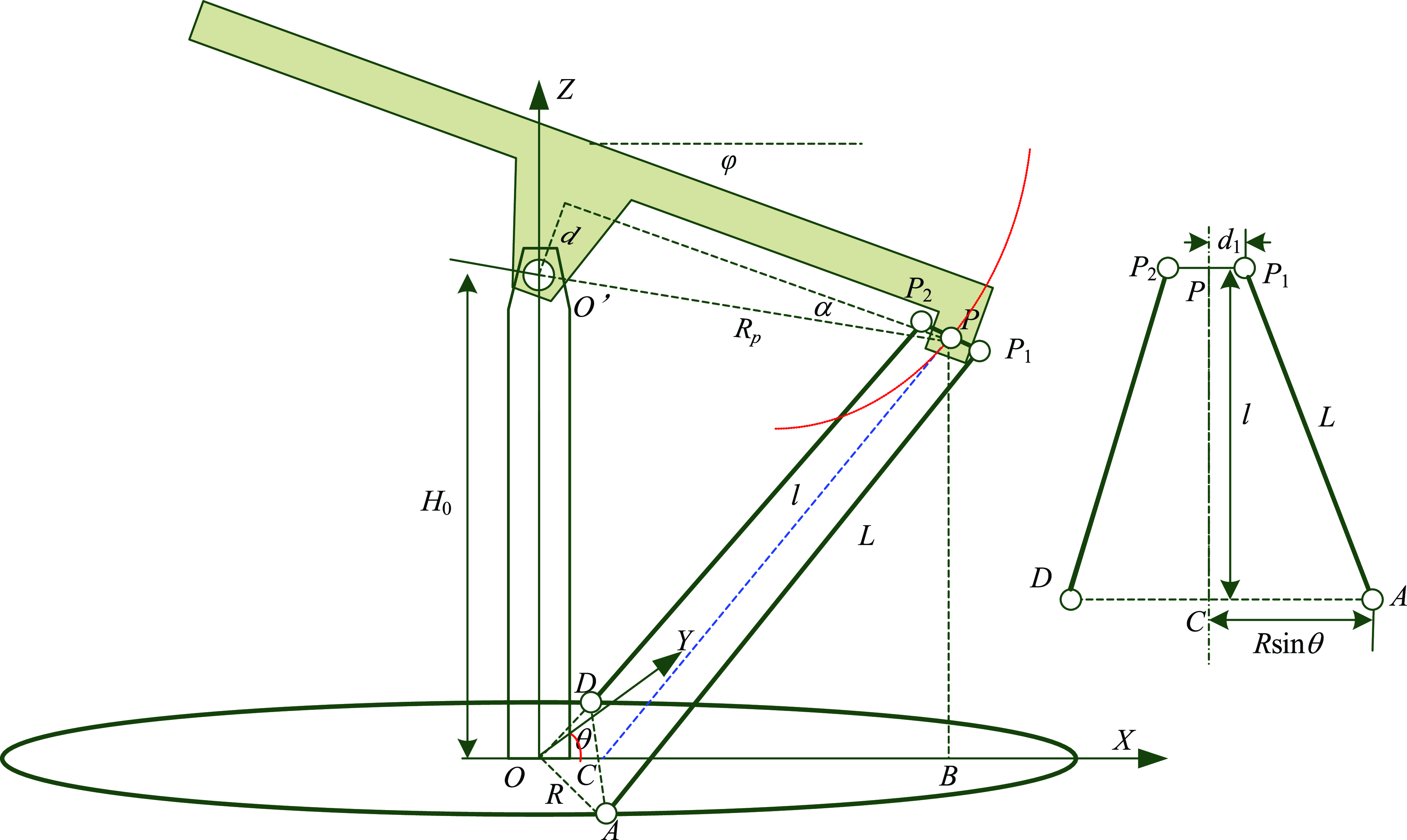
From Fig. 3, one can notice that the length of the rod L is a constant value. The movement of the antenna platform will cause the height $l$
and the bottom edge
$l$
and the bottom edge $AC$
of trapezoid
$AC$
of trapezoid $PP_{1}AC$
and the sides of triangle
$PP_{1}AC$
and the sides of triangle $PBC$
to change. According to the position relationship of the trapezoid and triangle, one can obtain as follows.
$PBC$
to change. According to the position relationship of the trapezoid and triangle, one can obtain as follows.
 \begin{equation} \left[H_{0}-R_{P}\sin \!\left(\varphi -\alpha \right)\right]^{2}+\left[R_{p}\cos \!\left(\varphi -\alpha \right)-R\cos \theta \right]^{2}+\left(R\sin \theta -d_{1}\right)^{2}=L^{2} \end{equation}
Expanding Eq. (5) and simplifying it yields
 \begin{equation} \theta =\arccos \frac{d_{1}^{2}+{H_{0}}^{2}+R^{2}-L^{2}-2H_{0}R_{P}\sin \!\left(\varphi -\alpha \right)}{2R\sqrt{R_{P}^{2}\cos ^{2}\left(\varphi -\alpha \right)+d_{1}^{2}}}+\arccos \frac{R_{P}\cos \!\left(\varphi -\alpha \right)}{\sqrt{R_{P}^{2}\cos ^{2}\left(\varphi -\alpha \right)+d_{1}^{2}}} \end{equation}
Under the condition that the antenna azimuth angle $\gamma$
is not
$\gamma$
is not $0^{\circ }$
, the point
$0^{\circ }$
, the point $A$
and
$A$
and $D$
azimuth angles are unequal. According to the geometric symmetry relationship of the 2-dof parallel antenna, point
$D$
azimuth angles are unequal. According to the geometric symmetry relationship of the 2-dof parallel antenna, point $A$
azimuth
$A$
azimuth $\theta _{2}$
and point
$\theta _{2}$
and point $D$
azimuth
$D$
azimuth $\theta _{1}$
can be obtained.
$\theta _{1}$
can be obtained.
 \begin{equation} \left\{\begin{array}{l} \theta _{1}=\gamma +\theta \\ \theta _{2}=\gamma -\theta \end{array}\right. \end{equation}
Equations (5)–(7) are the inverse kinematics equations of the 2-dof parallel robotic antenna pedestal.
3.2. Forward kinematics
The forward kinematics of the 2-dof parallel robotic antenna pedestal is derived from Eq. (5) as follows.
 \begin{equation} R\cos \theta \cos \!\left(\varphi -\alpha \right)+H_{0}\sin \!\left(\varphi -\alpha \right)=\frac{d_{1}^{2}+H_{0}^{2}+R_{p}^{2}+R^{2}-L^{2}-2d_{1}R\sin \theta }{2R_{P}} \end{equation}
Simplifying Eq. (8) yields
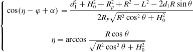 \begin{equation} \left\{\begin{array}{ll} \displaystyle \cos \!\left(\eta -\varphi +\alpha \right) & =\dfrac{d_{1}^{2}+H_{0}^{2}+R_{p}^{2}+R^{2}-L^{2}-2d_{1}R\sin \theta }{2R_{P}\sqrt{R^{2}\cos ^{2}\theta +H_{0}^{2}}}\\[18pt] & \!\!\!\!\!\!\displaystyle \eta =\arccos \frac{R\cos \theta }{\sqrt{R^{2}\cos ^{2}\theta +H_{0}^{2}}} \end{array}\right. \end{equation}
Further, the forward relationship between $\theta$
and
$\theta$
and $\gamma, \varphi$
is as follows.
$\gamma, \varphi$
is as follows.
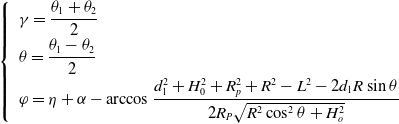 \begin{equation} \left\{\begin{array}{ll} & \displaystyle \gamma =\frac{\theta _{1}+\theta _{2}}{2}\\[6pt] & \displaystyle \theta =\frac{\theta _{1}-\theta _{2}}{2}\\[6pt] & \displaystyle \varphi =\eta +\alpha -\arccos \frac{d_{1}^{2}+H_{0}^{2}+R_{p}^{2}+R^{2}-L^{2}-2d_{1}R\sin \theta }{2R_{P}\sqrt{R^{2}\cos ^{2}\theta +H_{o}^{2}}} \end{array}\right. \end{equation}
Equation (10) is the forward kinematics equations of the parallel robotic antenna pedestal.
3.3. Jacobian matrix
Since the actual control requires speed control of the drive motor, it is necessary to solve the velocity relationship equation of the antenna model. The equation is a Jacobian matrix, also known as the first-order motion influence coefficient, which is a mapping between the speed of the operating mechanism and the end speed [Reference Watson, Obregon and Morimoto17].
Derivation of Eq. (6) concerning time t gives
 \begin{equation}\dot\theta=(m+n)\dot\varphi\end{equation}
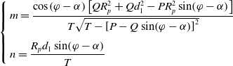 \begin{equation} \left\{\begin{array}{l} \displaystyle m=\frac{\cos \!\left(\varphi -\alpha \right)\left[QR_{p}^{2}+Qd_{1}^{2}-PR_{p}^{2}\sin \!\left(\varphi -\alpha \right)\right]}{T\sqrt{T-\left[P-Q\sin \!\left(\varphi -\alpha \right)\right]^{2}}}\\[16pt] \displaystyle n=\frac{R_{p}d_{1}\sin \!\left(\varphi -\alpha \right)}{T} \end{array}\right. \end{equation}
where
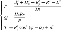 \begin{equation} \left\{\begin{array}{ll} \displaystyle P & =\dfrac{d_{1}^{2}+H_{0}^{2}+R_{p}^{2}+R^{2}-L^{2}}{2R}\\[6pt] \displaystyle Q & =\dfrac{H_{0}R_{P}}{R}\\[9pt] \displaystyle T & =R_{p}^{2}\cos ^{2}\left(\varphi -\alpha \right)+d_{1}^{2} \end{array}\right. \end{equation}
According to the geometric symmetry relationship of the 2-dof parallel antenna pedestal, the velocity relation between antenna platform attitude and driving sliders $A$
and
$A$
and $D$
can be further obtained from Eqs. (10) to (11) as follows [Reference Ahlawat, Prasad M.P. and Chauhan5].
$D$
can be further obtained from Eqs. (10) to (11) as follows [Reference Ahlawat, Prasad M.P. and Chauhan5].
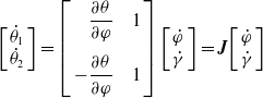 \begin{equation}\left[\begin{array}{l}\dot{\theta}_{1}\\ \dot\theta_{2}\end{array}\right]=\left[\begin{array}{r@{\quad}l}\dfrac{\partial \theta}{\partial \varphi} & 1\\[13pt] -\dfrac{\partial\theta}{\partial \varphi} & 1 \end{array}\right]\left[\begin{array}{l} \dot{\varphi} \\ \dot{\gamma}\end{array}\right]=\boldsymbol{J}\!\left[\begin{array}{l} \dot{\varphi} \\ \dot{\gamma}\end{array}\right]\end{equation}
where J is the Jacobian matrix.
4. Control system design
From the engineering point of view, it is not only necessary to ensure that the antenna can reach the specified attitude but also need to be able to ensure the speed of antenna attitude changes. It is meaningful for capturing the signal of moving target. In this paper, the azimuth and pitch of the parallel robotic antenna pedestal are coupled and jointly determined by the two drive sliders. So it is vital to ensure the motion speed of the two drive motors for trajectory tracking. A well-designed control strategy is of great importance for a control system. On one hand, it will make up for the low accuracy and other defects of their own caused by some system parameters perturbation; on the other hand, it will also be able to improve the stability of the system [Reference He, Wu and Li11].
Since the parallel robotic antenna pedestal servo system contains nonlinear factors such as friction and tooth gap, it is challenging to establish an accurate mathematical model. In order to achieve high-precision control, a fuzzy logic PI controller is used.
4.1. Overall structure of the controller
As the attitude change of the antenna pedestal during the operation process will cause the two drive motor load to change asynchronously, as well as the influence of nonlinear friction and other uncertainty disturbances, the actual operating speed of the drive motor will not match the expectation. For speed error, the PD controller of motor speed, as shown in Fig. 4, is designed by using a proportional unit and differential unit.
Basic control system for speed loop.
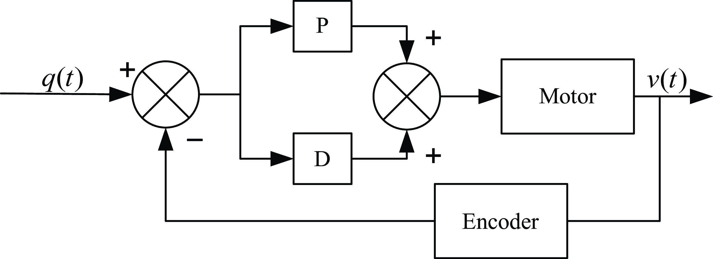
Even if the PD controller in Fig. 4 is implemented in the actual operation, the antenna attitude still inevitably generates accumulated errors during the speed adjustment process, which leads to the reduction of real-time, accuracy and reliability of antenna position control. Moreover, the antenna orientation and pitch error brought by the motor speed error display nonlinear effect.
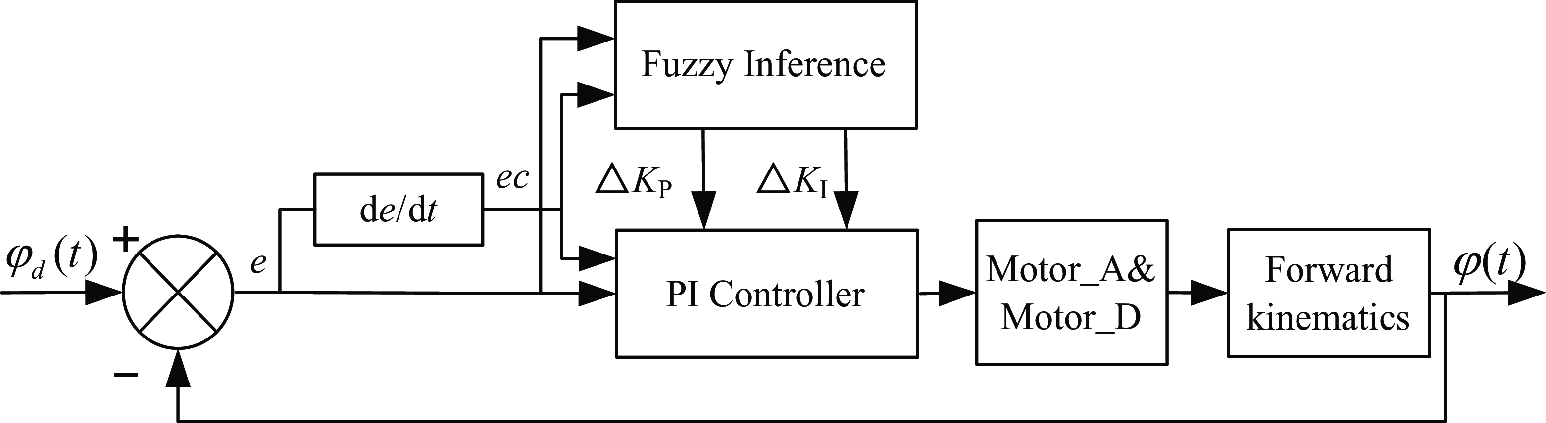
In this paper, by assuming that there is no error in the feedback of the encoder of the drive motor, one can calculate the position of drive motor in the antenna circular track. With the real-time position of the drive motor, the attitude of the antenna platform can be derived by using the forward kinematics. This paper designs the FPI controller using attitude feedback of the antenna pedestal, as shown in Fig. 5. The design idea is to integrate fuzzy theory and PI control algorithm to form a fuzzy PI controller. One can determine the fuzzy relationship between two parameters of the PI controller and attitude deviation $e$
and attitude deviation change rate
$e$
and attitude deviation change rate $ec$
.
$ec$
.
Improved control system for position loop.
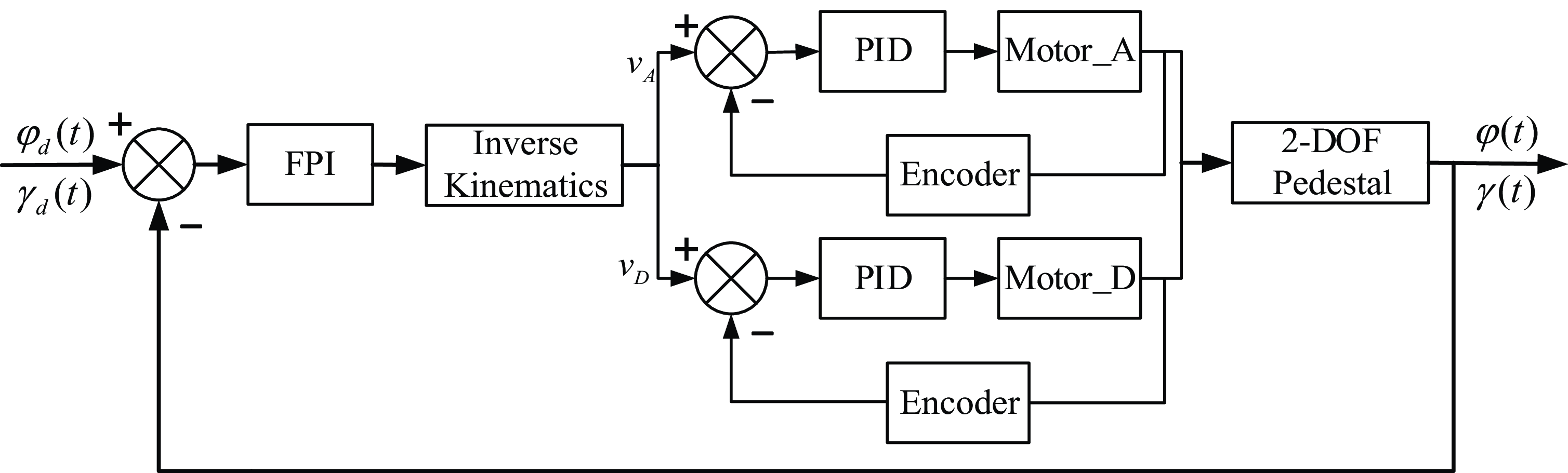
In this paper, the azimuth and pitch motion of the antenna is jointly determined by two drive sliders, so it is crucial to ensure the motion speed and trajectory of the two drive motors simultaneously for trajectory tracking. Either of the above controllers can hardly meet the real-time trajectory tracking of antenna, so the dual closed-loop controller shown in Fig. 6 is designed by combining the two control strategies, in which the inner-loop speed controller controls the motor based on the speed feedback from the encoder. The outer loop position controller determines the antenna platform attitude according to the motor encoder and then feeds back to the FPI controller to control the antenna pedestal with the kinematic model.
FPI control schematic.
4.2. FPI controller
The above motor speed loop is a PD controller, and its control rate $u_{i}(t)$
can be designed as
$u_{i}(t)$
can be designed as
 \begin{equation}u_{i}(t)=K_{P}e_{i}(t)+K_{D}\dot{e}_{i}(t),i=1,2 \end{equation}
where $e_{i}(t)$
is the motor speed error,
$e_{i}(t)$
is the motor speed error, $i$
denotes two motors,
$i$
denotes two motors, $K_{P}$
and
$K_{P}$
and $K_{D}$
are the proportional and integral parameters, respectively. The
$K_{D}$
are the proportional and integral parameters, respectively. The $PD$
controller parameters can be adjusted by the classical method [Reference Jinhua and Jian18].
$PD$
controller parameters can be adjusted by the classical method [Reference Jinhua and Jian18].
Due to the complexity of the parallel robotic antenna pedestal in the control process and the difficulty of establishing an accurate mathematical model, it is difficult to obtain the desired performance index in the interference environment. For the position control loop, one uses the FPI controller to track the trajectory. The FPI controller is designed as follows.
 \begin{equation} \Delta \boldsymbol{u}_{\boldsymbol{F}}\!\left(t\right)=\boldsymbol{k}_{\boldsymbol{u}}\cdot F\!\left[\boldsymbol{k}_{\boldsymbol{e}}\cdot \boldsymbol{e}_{\boldsymbol{F}}\!\left(t\right),\boldsymbol{k}_{\boldsymbol{ec}}\cdot \boldsymbol{e}\boldsymbol{c}_{\boldsymbol{F}}\!\left(t\right)\right] \end{equation}
where $\Delta \boldsymbol{u}_{\boldsymbol{F}}(t)$
is the fuzzy logic output value,
$\Delta \boldsymbol{u}_{\boldsymbol{F}}(t)$
is the fuzzy logic output value, $\boldsymbol{e}_{\boldsymbol{F}}(t)$
and
$\boldsymbol{e}_{\boldsymbol{F}}(t)$
and $\boldsymbol{e}\boldsymbol{c}_{\boldsymbol{F}}(t)$
are the error and error change rate of the antenna platform attitude,
$\boldsymbol{e}\boldsymbol{c}_{\boldsymbol{F}}(t)$
are the error and error change rate of the antenna platform attitude, $F[\cdot ]$
is the two-input two-output operation based on fuzzy inference,
$F[\cdot ]$
is the two-input two-output operation based on fuzzy inference, $\boldsymbol{k}_{\boldsymbol{e}}$
and
$\boldsymbol{k}_{\boldsymbol{e}}$
and $\boldsymbol{k}_{\boldsymbol{ec}}$
are the quantization factors of the error in the fuzzy mapping relationship,
$\boldsymbol{k}_{\boldsymbol{ec}}$
are the quantization factors of the error in the fuzzy mapping relationship, $\boldsymbol{k}_{\boldsymbol{u}}$
is the scaling factor of the fuzzy result.
$\boldsymbol{k}_{\boldsymbol{u}}$
is the scaling factor of the fuzzy result.
Based on Eq. (16), taking the pitch controller in the position loop as an example, the control rate $u_{F}(t)$
is designed as [Reference Mao and He19, Reference Shayeghi, Younesi and Hashemi20]
$u_{F}(t)$
is designed as [Reference Mao and He19, Reference Shayeghi, Younesi and Hashemi20]
 \begin{equation} u_{F}\!\left(t\right)=\left[K_{{P_{0}}}+\Delta u_{{F_{1}}}\left(t\right)\right]e\!\left(t\right)+\int _{0}^{t}\!\left[K_{{I_{0}}}+\Delta u_{{F_{2}}}\!\left(t\right)\right]e\!\left(t\right)dt \end{equation}
where $K_{{P_{0}}}$
and
$K_{{P_{0}}}$
and $K_{{I_{0}}}$
are the initial values of the FPI controller,
$K_{{I_{0}}}$
are the initial values of the FPI controller, $\Delta u_{{F_{1}}}(t)$
and
$\Delta u_{{F_{1}}}(t)$
and $\Delta u_{{F_{2}}}(t)$
are the element in
$\Delta u_{{F_{2}}}(t)$
are the element in $\Delta \boldsymbol{u}_{\boldsymbol{F}}(t)$
, and
$\Delta \boldsymbol{u}_{\boldsymbol{F}}(t)$
, and $e(t)$
is the pitch angle error. The azimuth attitude controller takes the similar procedure.
$e(t)$
is the pitch angle error. The azimuth attitude controller takes the similar procedure.
As mentioned above, implementing the FPI controller requires several parts: quantization and scaling factors, fuzzification, rule base, inference rules, and defuzzification. These issues are briefly discussed below [Reference Yakubu, Thomas, Hussein, Anye, Koyunlu and Oshiga21].
-
• Quantization and scaling factors. FPI controller uses normalized input and output values. So the input and output variables need to be multiplied by the corresponding factors to translate into the fuzzy theoretical domain. The scope of the discussion domain (U) is [−3, 3]. Similarly, the fuzzy output needs to be multiplied by the scaling factor, and the output discussion domain is [−3, 3].
-
• Fuzzification. The inputs of the fuzzy controller are the error $e$
and the error rate of change
$ec$
, and the outputs are the PI parameter change values (
$\Delta K_{P},\Delta K_{I}$
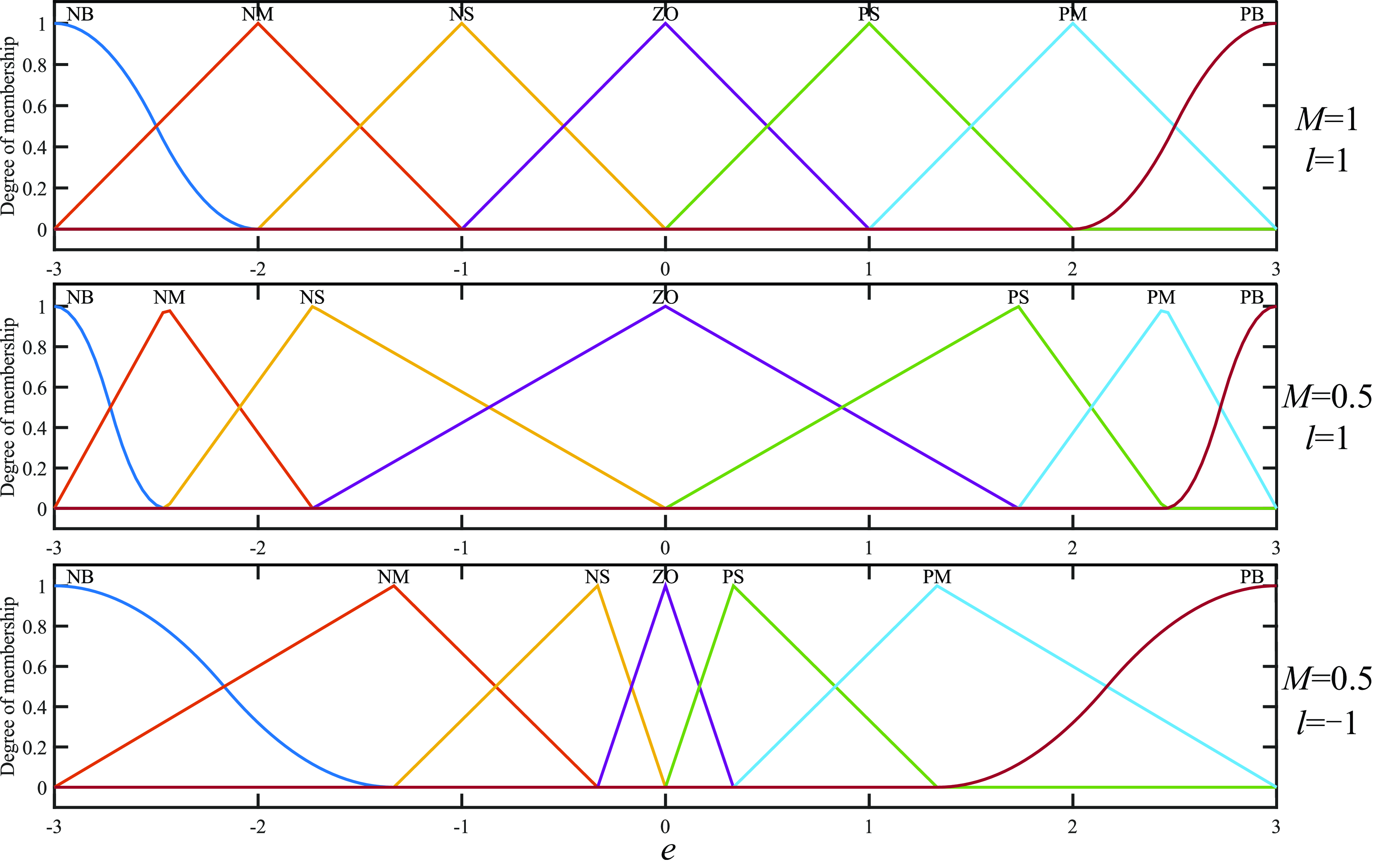
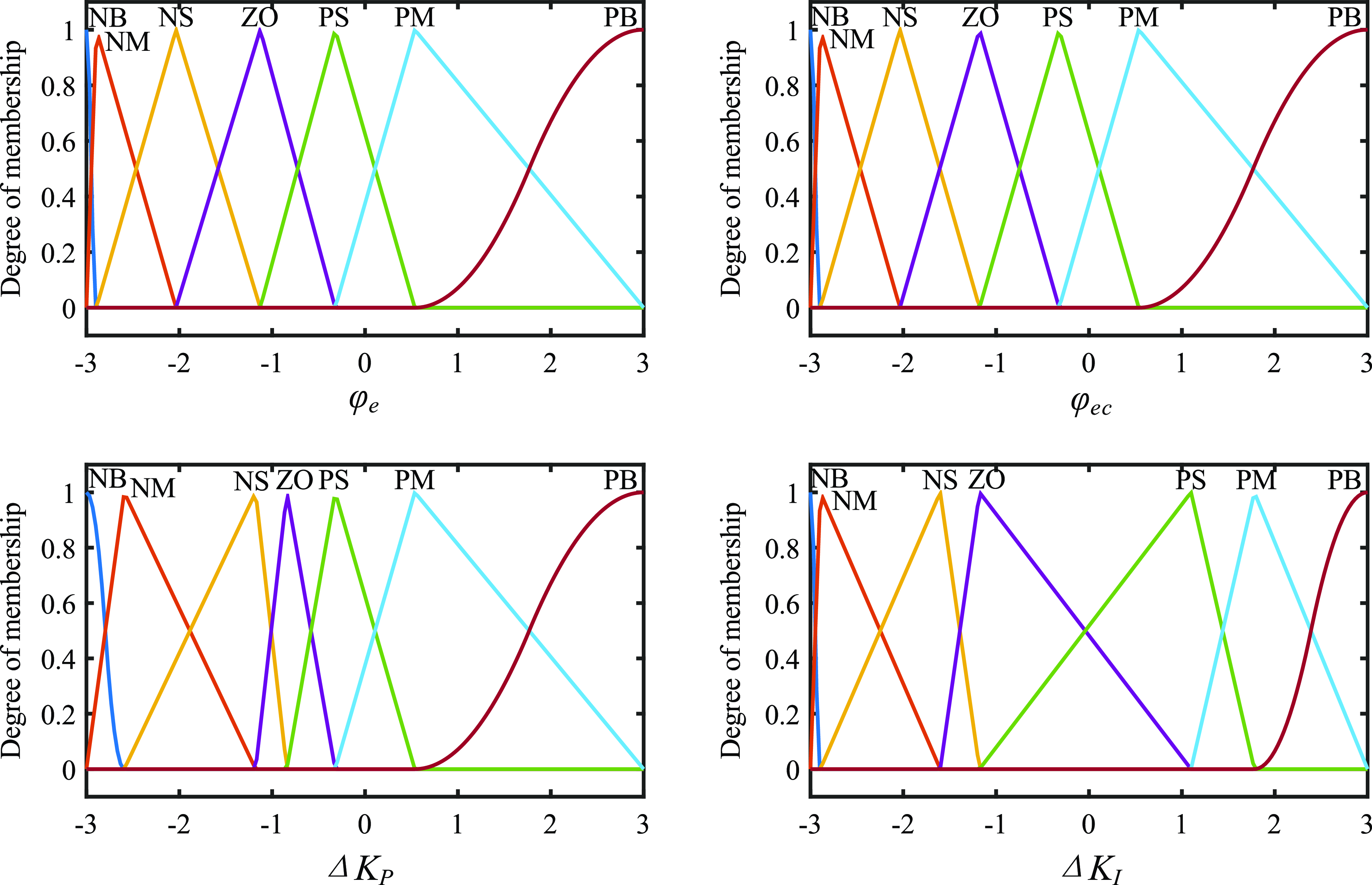
). In this paper, the input and output membership function uses Gaussian and trigonometric functions, as shown in Fig. 7. For membership functions, “N” represents the “Negative” fuzzy set, “Z” represents “Zero,” “P” is “Positive,” “S” is “Small,” “M” is “Medium,” and finally “B” is “Big” [Reference Safari, Ardehali and Sirizi22].
$e$
and the error rate of change
$ec$
, and the outputs are the PI parameter change values (
$\Delta K_{P},\Delta K_{I}$
). In this paper, the input and output membership function uses Gaussian and trigonometric functions, as shown in Fig. 7. For membership functions, “N” represents the “Negative” fuzzy set, “Z” represents “Zero,” “P” is “Positive,” “S” is “Small,” “M” is “Medium,” and finally “B” is “Big” [Reference Safari, Ardehali and Sirizi22]. -
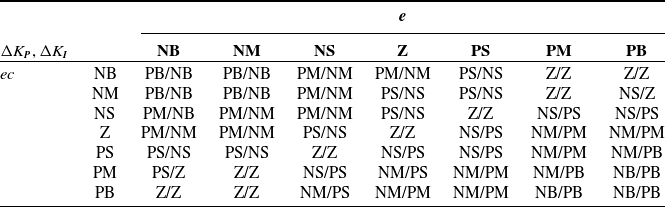
• Rule base. The key to the fuzzy controller is the rule base, which is in the form of “If-Then” statements and logical “sum” operations, for example, If
$e$
= NB AND
$ec$
= NM, THEN
$\Delta K_{\boldsymbol{P}}$
= PB,
$\Delta K_{\boldsymbol{I}}$
= NB. Table II shows a typical rule base. -
• Inference rules. The Mamdani minimum implication method is used to generate the overall control behavior according to the contribution of each rule.
-
• Defuzzification. The defuzzification is the centroid method. It returns the coordinates of the centroid of the area enclosed by the fuzzy output curve as the exact output value.


Fuzzy controller rule base.
Membership function distribution of different parameters.
It should be noted that the distribution of membership functions and fuzzy rule base directly affect the control performance. However, there are no effective theoretical methods, and most scholars design them according to experience. So this paper uses genetic algorithm to optimize FPI controller parameters. This section discusses its coding method in advance.
The first type is the improved full coding method, which takes all membership function vertices, low points and every rule in the rule base as variables. In order to ensure the results are effective and convergent in the iterative process, constraints based on control experience are added to each variable [Reference Cheong and Lai23]. The specific implementation method is not described in this paper.
The second type is the feature-based coding method to extract the distribution of membership function curves and fuzzy rules [Reference Park, Cho and Cha24]. For the feature of the membership function, “Z” can be considered to remain unchanged, and the vertices of other functions are distributed symmetrically. The density $D_{i}$
of other vertex positions and point 0 is expressed as
$D_{i}$
of other vertex positions and point 0 is expressed as
 \begin{equation} D_{i}=\left| \frac{i}{\left(k-1\right)\!/2}\right| ^{P},i=1,2,\ldots,\frac{k-1}{2} \end{equation}
where $k$
is the number of membership function fuzzy sets,
$k$
is the number of membership function fuzzy sets, $i$
represents the order of membership functions,
$i$
represents the order of membership functions, $P$
is the exponent of the power function, and its value affects the density distribution of each vertex of the membership function [Reference Jahedi and Ardehali25].
$P$
is the exponent of the power function, and its value affects the density distribution of each vertex of the membership function [Reference Jahedi and Ardehali25].
 \begin{equation} P=M^{l} \end{equation}
where $M\in [0.1,1], l\in \{-1,1\}$
the value of
$M\in [0.1,1], l\in \{-1,1\}$
the value of $l$
indicates concentration towards 0 or boundary.
$l$
indicates concentration towards 0 or boundary.
Only two parameters $M$
and
$M$
and $l$
are required for the feature encoding of membership function distribution. The membership function distribution of different feature parameters is as follows.
$l$
are required for the feature encoding of membership function distribution. The membership function distribution of different feature parameters is as follows.
For the feature of the rule base, it can be observed from Table II that the rules can be divided into several regions with the same rule results, and the number of regions depends on the number of fuzzy sets $k$
.
$k$
.
From the above description, a phase plane can be established with two input variables $e$
and
$e$
and $ec$
as axes, as shown in Fig. 8. Grid lines represent the “If” part of fuzzy rules, and grid points represent each rule. After that, the grid points are divided into k regions by the dotted lines in the figure.
$ec$
as axes, as shown in Fig. 8. Grid lines represent the “If” part of fuzzy rules, and grid points represent each rule. After that, the grid points are divided into k regions by the dotted lines in the figure.
Phase plane segmentation under different parameters.
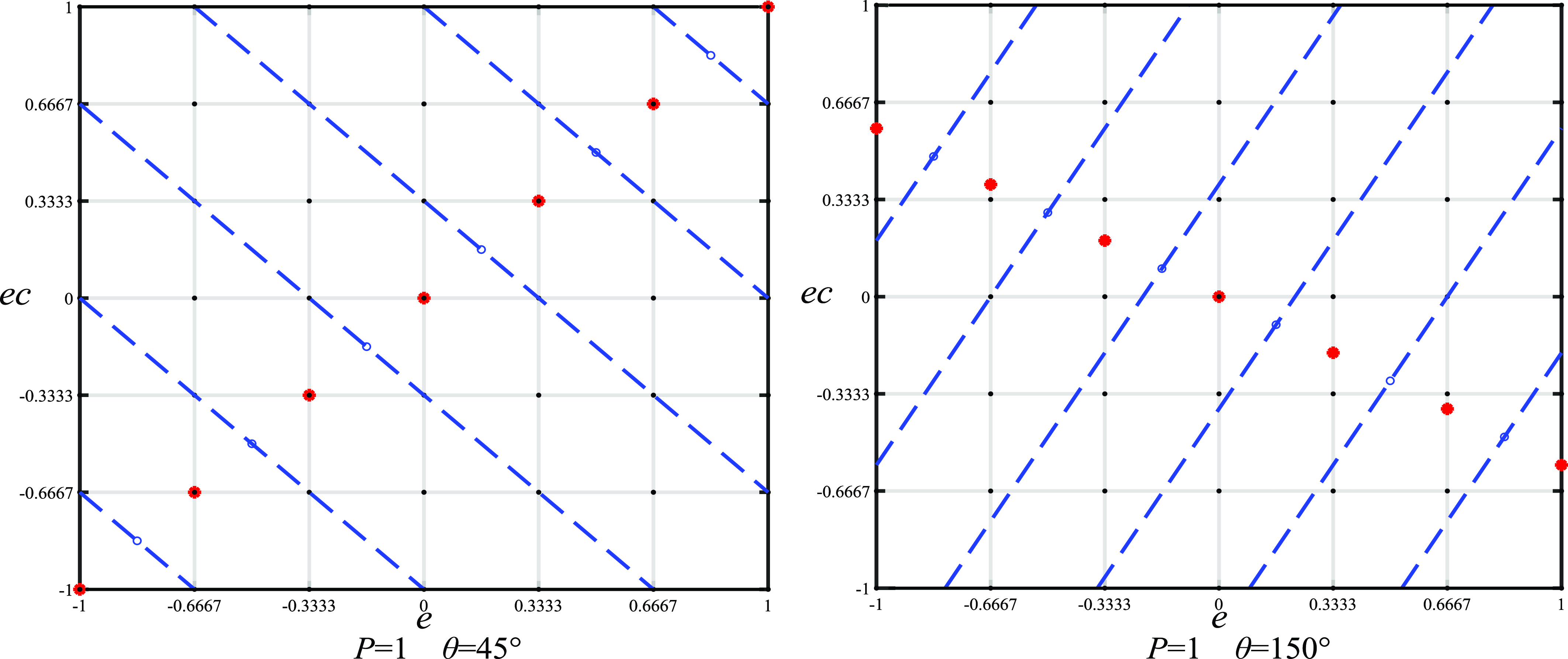
The dotted lines in Fig. 8 are perpendicular bisectors of adjacent big red points whose coordinates are defined as follows.
 \begin{equation} \left\{\begin{array}{ll} x_{i} & =L\text{sign}\!\left(i\right)\left| \frac{i}{\left(k-1\right)/2}\right| ^{P}\\ y_{i} & =x_{i}\tan \theta \end{array}\right.,i=-\frac{k-1}{2},-\frac{k-2}{2},\ldots,0,\ldots,\frac{k-1}{2} \end{equation}
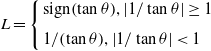 \begin{equation} L=\left\{\begin{array}{l} \displaystyle \text{sign}\!\left(\tan \theta \right)\!,\left| 1/\tan \theta \right| \geq 1\\[6pt] \displaystyle 1/\!\left(\tan \theta \right)\!,\left| 1/\tan \theta \right| \lt 1 \end{array}\right. \end{equation}
where $L$
is used to limit the segment point to fall in the phase plane, sign(·) is a sign function, and
$L$
is used to limit the segment point to fall in the phase plane, sign(·) is a sign function, and $\theta$
is the angle that the line of the split point rotates around the origin.
$\theta$
is the angle that the line of the split point rotates around the origin.
The value of the parameter $j, j\in \{-1,1\}$
determines the way in which the rules are filled into the divided phase plane. Elements of [NB, NM, NS, Z, PS, PM, PB] fill in the phase plane from top to bottom in the case where
$j, j\in \{-1,1\}$
determines the way in which the rules are filled into the divided phase plane. Elements of [NB, NM, NS, Z, PS, PM, PB] fill in the phase plane from top to bottom in the case where $j$
is 1, respectively. Fill in in the opposite direction, in the case where
$j$
is 1, respectively. Fill in in the opposite direction, in the case where $j$
is −1.
$j$
is −1.
It can be seen that only four parameters $M, l, \theta$
and
$M, l, \theta$
and $j$
are required for the feature encoding of the rule base. The fuzzy inference surface of the rule base with different parameters is shown in Fig. 9.
$j$
are required for the feature encoding of the rule base. The fuzzy inference surface of the rule base with different parameters is shown in Fig. 9.
Rule base under different parameters.
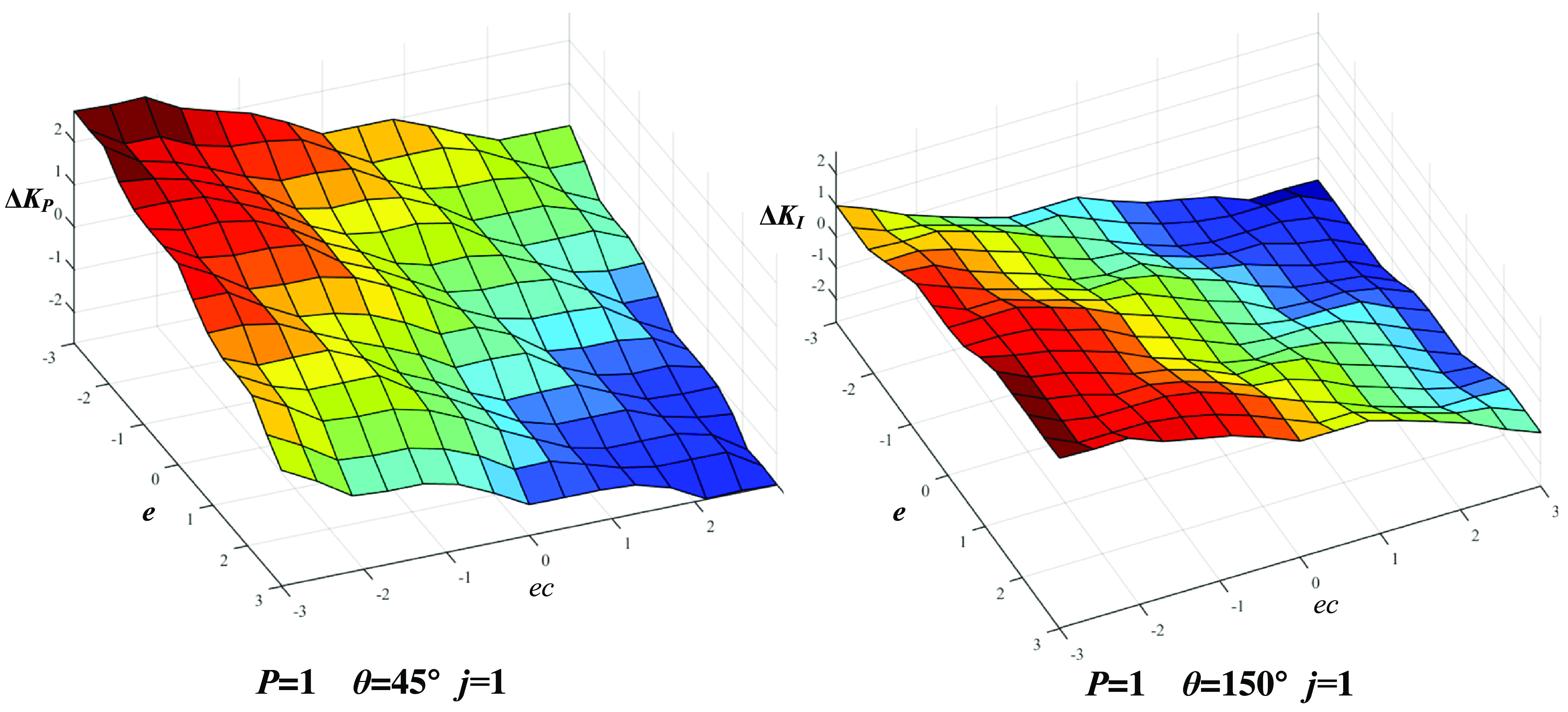
Based on feature coding, the number of variables of the FPI controller can be reduced from 352 to 32, 90.9% reduction of computation.
5. Simulation and experiment
Selecting an appropriate set of parameters for the FPI controller can greatly improve the actual control effect. Therefore, this chapter first verifies the effect of the controller through simulation experiments and then finds the most suitable design parameters for this antenna pedestal through the ITAE performance index and differential evolution algorithm. Finally, a prototype is established and the trajectory tracking effect of different controllers is compared.
5.1. Simulation experiment and optimization
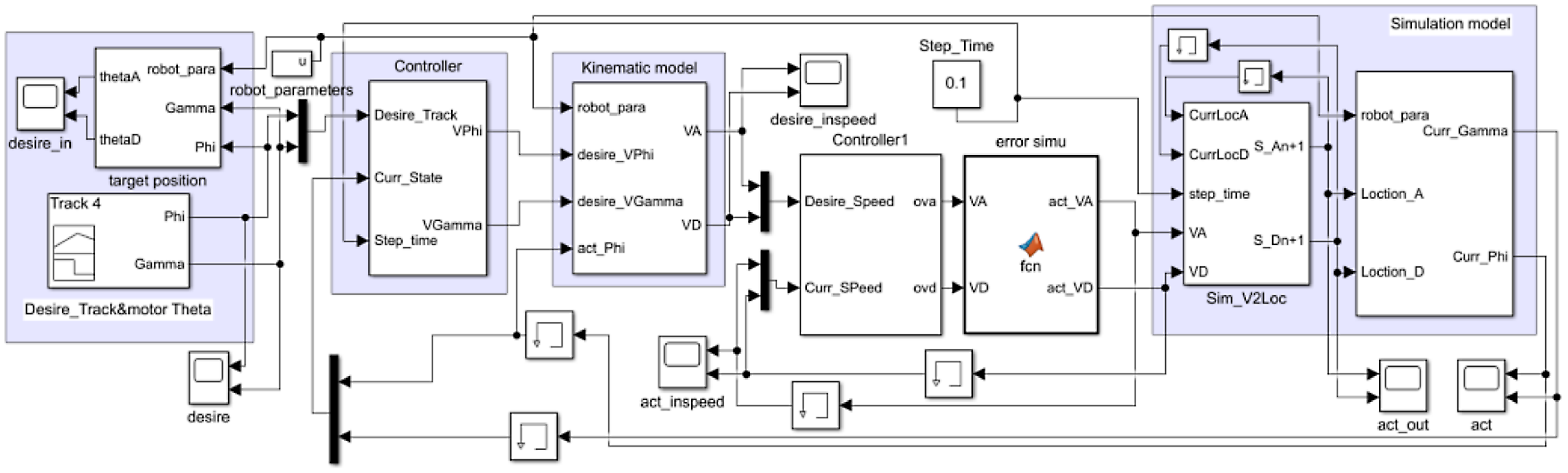
In this section, MATLAB/Simulink is used to establish the simulation model in Fig. 10, which is used to simulate the performance of the antenna pedestal under different control strategies [Reference Wen, Zheng, Jia, Ji, Hao and Lam16]. The simulation model includes a trajectory generator, antenna pedestal kinematic model, inner and outer loop controller, error generation module, etc. By inputting different trajectories and adjusting the error module parameters, the dynamic response of the antenna pedestal under different control strategies can be simulated.
Simulink simulation model.
Desired attitude trajectory of antenna.
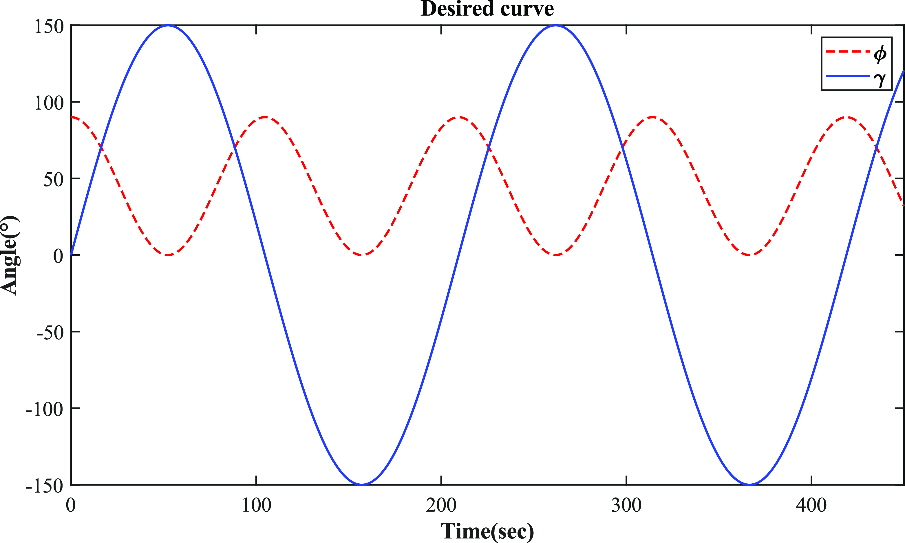
In this case, the typical motion trajectory of the antenna platform is set as
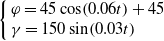 \begin{equation} \left\{\begin{array}{l} \varphi =45\cos \!\left(0.06t\right)+45\\ \gamma =150\sin \!\left(0.03t\right) \end{array}\right. \end{equation}
And the simulation desired curve of the antenna platform is shown in Fig. 11.
The traditional parameter tuning method is no longer applicable to this model. The ITAE index is mainly used in engineering to evaluate the control system performance [Reference Rai and Das26], that is, the time multiplied by the absolute value of the error integral as in Eq. (23). It is a comprehensive performance evaluation index that integrates the rapidity and stability, which has good engineering practicality.
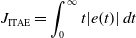 \begin{equation} J_{\text{ITAE}}=\int _{0}^{\infty }t\!\left| e\!\left(t\right)\right| dt \end{equation}
The parameter optimization of the FPI controller is to constantly adjust the vector $\boldsymbol{Z}$
of the parameters of the FPI controller through the simulation model and find the optimal value of
$\boldsymbol{Z}$
of the parameters of the FPI controller through the simulation model and find the optimal value of $\boldsymbol{Z}$
in the parameter feasible region to minimize the value of the performance index
$\boldsymbol{Z}$
in the parameter feasible region to minimize the value of the performance index $J_{\text{ITAE}}$
. The optimization model is as follows.
$J_{\text{ITAE}}$
. The optimization model is as follows.
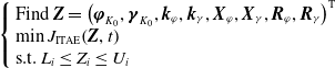 \begin{equation} \left\{\begin{array}{l} \text{Find }\boldsymbol{Z}=\left(\boldsymbol{\varphi }_{{K_{0}}},\boldsymbol{\gamma }_{{K_{0}}},\boldsymbol{k}_{\varphi },\boldsymbol{k}_{\gamma },\boldsymbol{X}_{\varphi },\boldsymbol{X}_{\gamma },\boldsymbol{R}_{\varphi },\boldsymbol{R}_{\gamma }\right)^{\mathrm{T}}\\ \min J_{\text{ITAE}}\!\left(\boldsymbol{Z},t\right)\\ \mathrm{s}.\mathrm{t}.\ L_{i}\leq Z_{i}\leq U_{i} \end{array}\right. \end{equation}
where subscripts $\varphi$
and
$\varphi$
and $\gamma$
represent pitch and azimuth controllers, respectively.
$\gamma$
represent pitch and azimuth controllers, respectively. $\boldsymbol{\varphi }_{{K_{0}}}$
and
$\boldsymbol{\varphi }_{{K_{0}}}$
and $\boldsymbol{\gamma }_{{K_{0}}}$
are the initial values of PI parameters in FPI controller,
$\boldsymbol{\gamma }_{{K_{0}}}$
are the initial values of PI parameters in FPI controller, $\boldsymbol{k}$
is the quantization and scaling factors,
$\boldsymbol{k}$
is the quantization and scaling factors, $\boldsymbol{X}$
is the parameters of membership function, and
$\boldsymbol{X}$
is the parameters of membership function, and $\boldsymbol{R}$
is the parameters of rule base,
$\boldsymbol{R}$
is the parameters of rule base, $L$
and
$L$
and $U$
are the lower and upper limits of the elements in the vector
$U$
are the lower and upper limits of the elements in the vector $\boldsymbol{Z}$
, respectively.
$\boldsymbol{Z}$
, respectively.
The parameter tuning process uses a differential evolution algorithm, which utilizes swarm intelligence. It is an optimization search algorithm generated by the cooperation and competition between individuals in the group, so it has strong global convergence capability and robustness [Reference Gao, Wang and Pedrycz27, Reference Pizarro-Lerma, García-Hernández and Santibáñez28]. After 150 iterations of computation, the ITAE index has the following trend.
Optimal FPI parameters table.

In Fig. 12, PI curve represents traditional PI control, FPI curve indicates that the fuzzy controller is not optimized, ALLCodeFPI curve indicates that the fuzzy controller has been optimized by full coding with empirical limitations, ShapeCode curve indicates that the fuzzy controller has been optimized by encoding the characteristic parameters.
ITAE index of different control strategies.
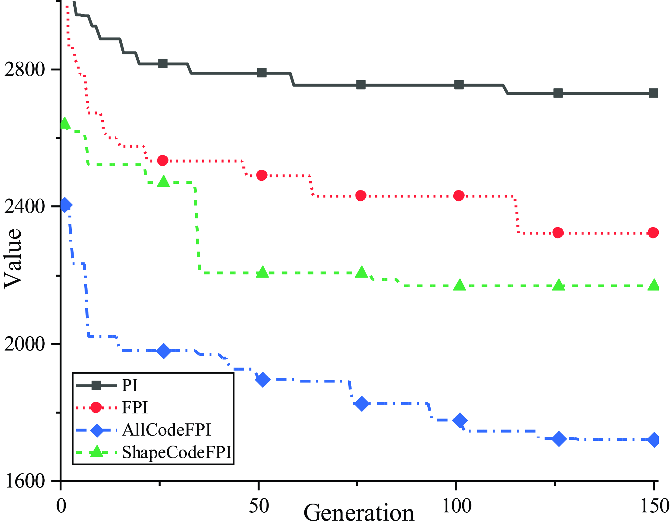
It can be observed from the comparison of ITAE results that compared with traditional PID control, FPI control reduces the ITAE index by 12.96%. If the fuzzy part of FPI is optimized, the ITAE index can be further reduced. And the optimization effect of full coding is better than feature coding. However, the computation amount of feature coding method is much less than that of full coding method, and the design parameters of fuzzy part of FPI can be determined quickly without experience.
In the simulation model shown in Fig. 10, FPI parameters are tuned by two coding methods respectively to track the desired trajectory shown in Fig. 11. The optimal FPI parameters are shown in Table III.
The optimal input and output membership function distributions of the FPI controller in $\varphi$
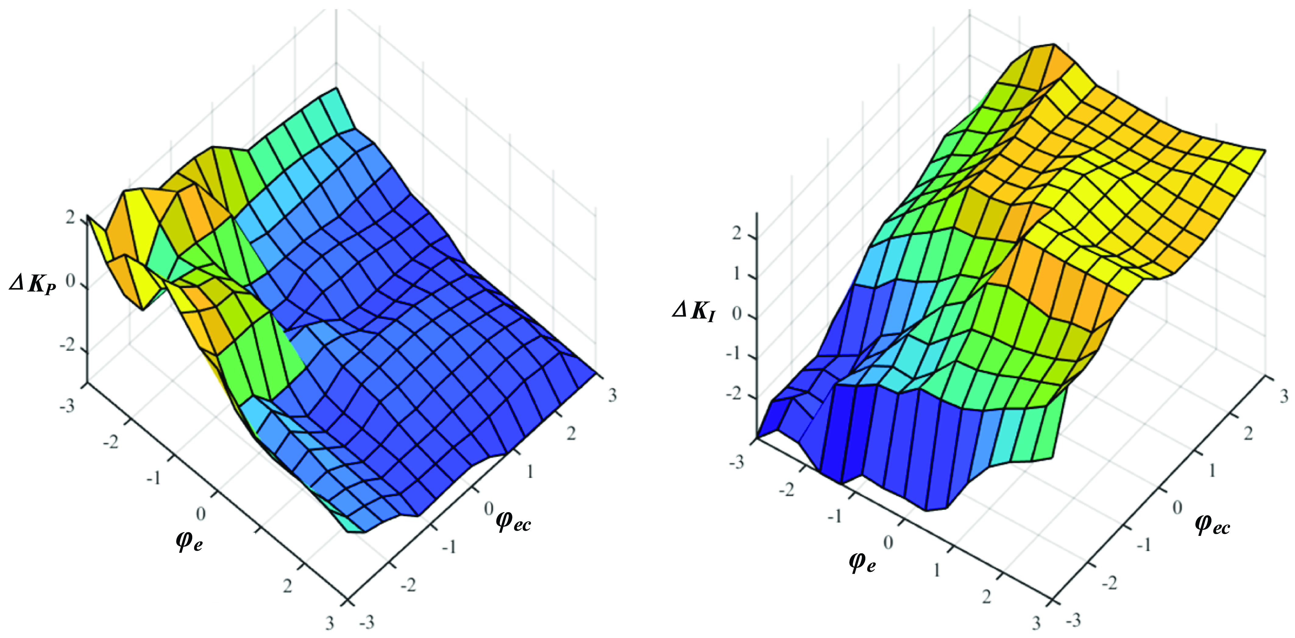
are shown in Fig. 13, and the optimal fuzzy inference surfaces of the
$\varphi$
are shown in Fig. 13, and the optimal fuzzy inference surfaces of the $\varphi$
rule base are shown in Fig. 14. Limited by the space, the membership function distributions of
$\varphi$
rule base are shown in Fig. 14. Limited by the space, the membership function distributions of $\gamma$
is omitted.
$\gamma$
is omitted.
Membership function distribution in $\varphi$
.
$\varphi$
.
Fuzzy inference surface in $\varphi$
.
$\varphi$
.
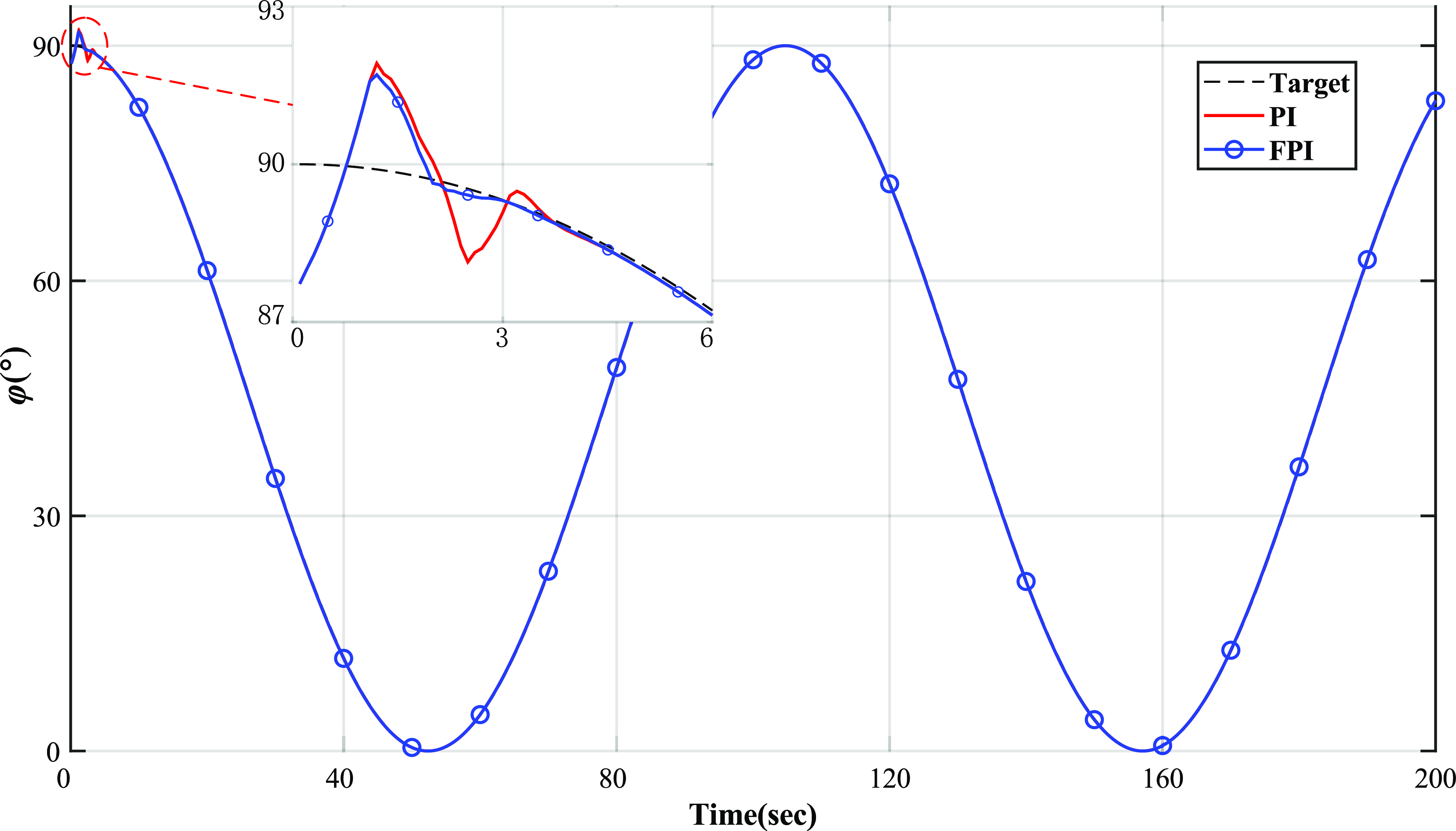
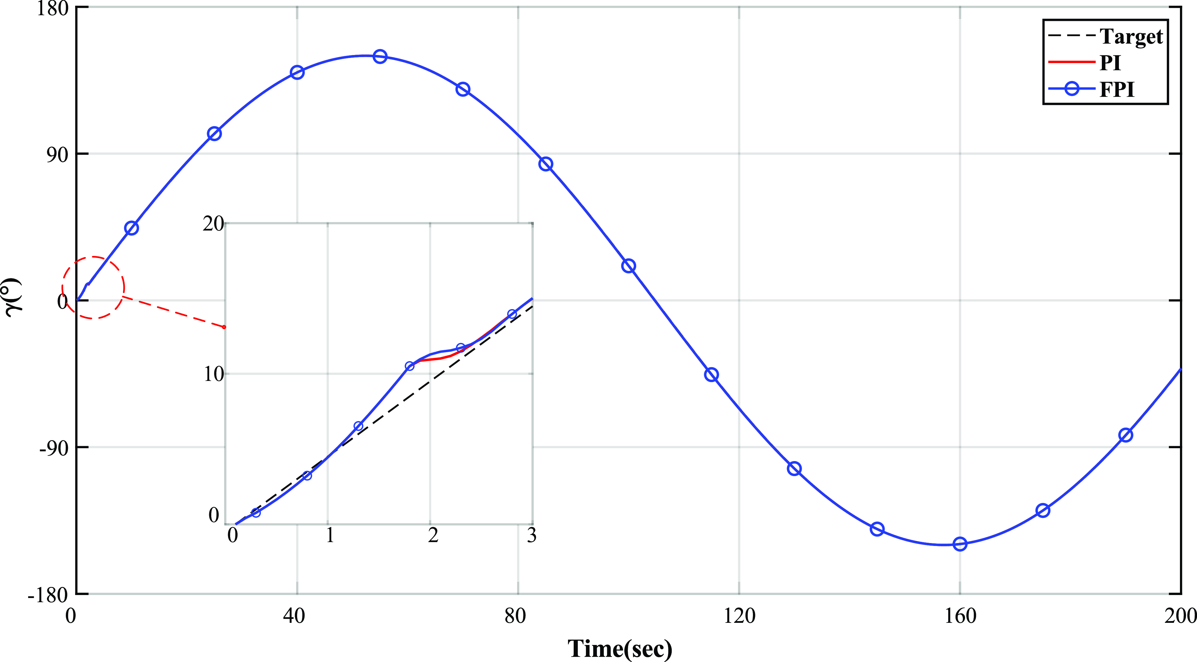
Then, the FPI controller with the optimized parameters and the traditional PI controller were used to track the desired trajectory in Fig. 11 in the Simulink model, respectively. The results of tracking pitch $\varphi$
curve of the antenna platform are shown in Fig. 15, and the results of tracking azimuth
$\varphi$
curve of the antenna platform are shown in Fig. 15, and the results of tracking azimuth $\gamma$
curve are shown in Fig. 16. Both Figs. 15 and 16 intercept and enlarge the details in tracking the antenna platform in the unstable startup stage.
$\gamma$
curve are shown in Fig. 16. Both Figs. 15 and 16 intercept and enlarge the details in tracking the antenna platform in the unstable startup stage.
Antenna pitch simulation trajectory.
Antenna azimuth simulation trajectory.
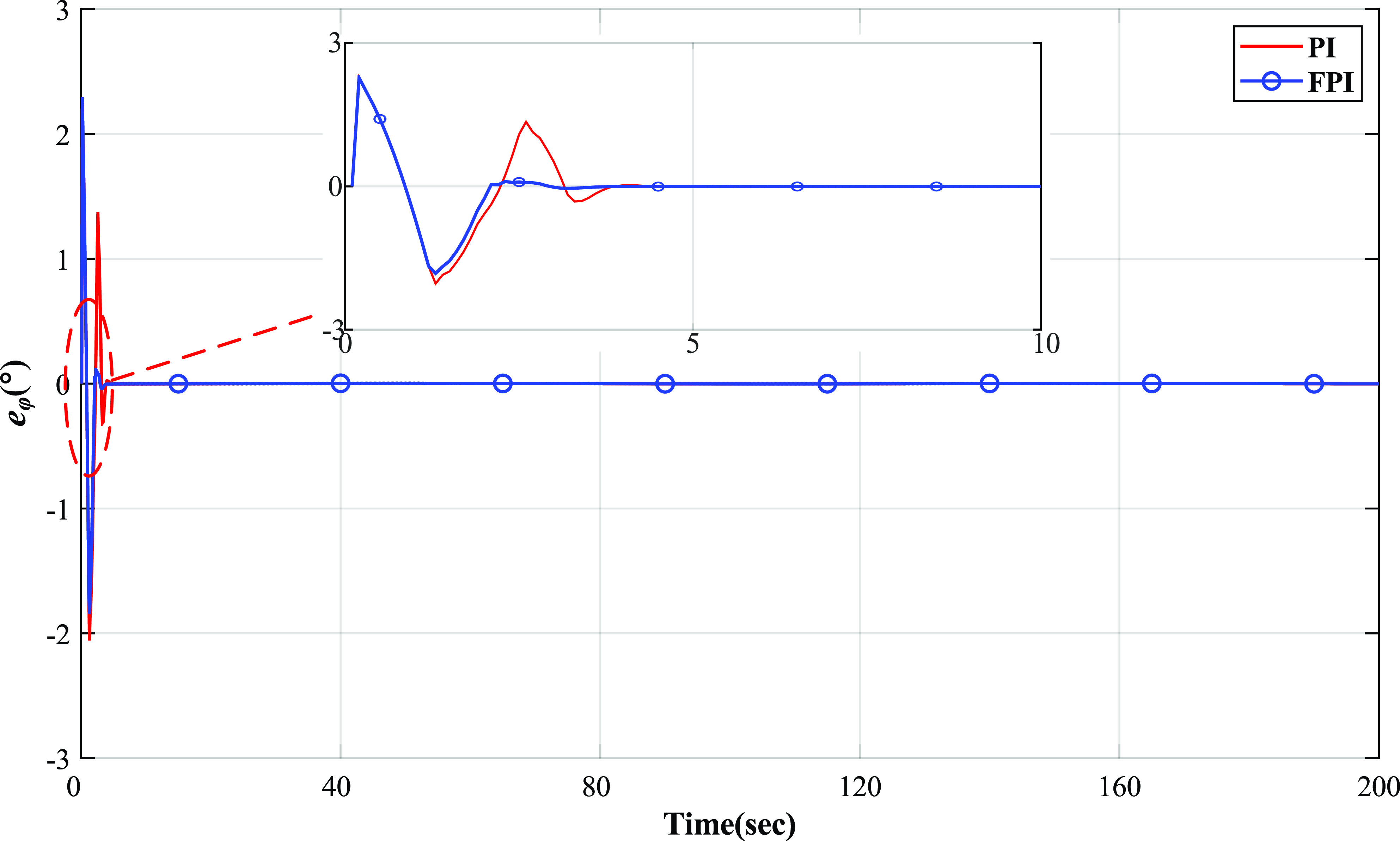
Besides, the pitch error and azimuth error of the desired trajectory tracked by the antenna platform are shown in Figs. 17 and 18, respectively. Both Figs. 17 and 18 also intercept and enlarge the details in error curve of the antenna platform during 0–10 s.
Pitch error curve of antenna.
Antenna azimuth error curve.
Parallel robotic antenna pedestal prototype.
The comparison of the results in Fig. 15 and Fig. 16 shows that the parallel robotic antenna pedestal has obvious nonlinear characteristics in pitching motion. Hence, the traditional PID control is difficult to achieve the desired control target. While the FPI can significantly improve its performance in pitch motion, as seen in the shortening of the system settling time. In the azimuthal motion, the antenna pedestal slider moves in the same direction and the system does not have prominent nonlinear characteristics, so the performance of FPI and traditional PI is almost the same.
5.2. Experiment
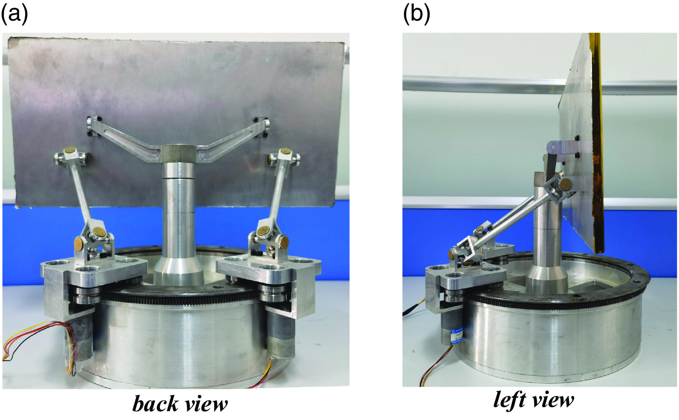
The parallel robotic antenna pedestal mechanism mainly comprises an antenna platform, central rotating shaft, fork arm, support rods, pedestal base, fixed circular track and driving slider. The driving slider moves in the circular track and realizes the attitude motion of the antenna platform through the movement transmission of the Hooke joints. The parallel robotic antenna pedestal prototype is shown in Fig. 19.
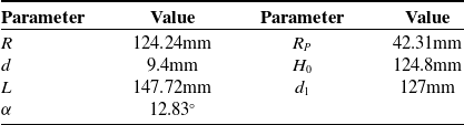
The main structural parameters of the antenna pedestal prototype are shown in Table IV.
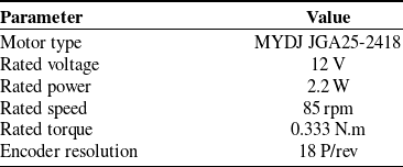
As the power supply and position feedback equipment of the antenna pedestal, the performance of the motor directly determines the performance of the antenna pedestal. Specifications of the hardware of the driving motor of the antenna seat are shown in Table V.
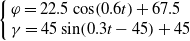
Then, in order to verify the trajectory tracking effect of the FPI controller with optimized parameters, the prototype in Fig. 19 is used to carry out the trajectory tracking experiment and the results are compared with that without ordinary position feedback control (nPCtrl) and that with PI controller. The experimental motion of the antenna adopts the sinusoidal curve conforming to the actual motion of the antenna, and the tracking curve is as follows.
 \begin{equation} \left\{\begin{array}{l} \varphi =22.5\cos \!\left(0.6t\right)+67.5\\ \gamma =45\sin \!\left(0.3t-45\right)+45 \end{array}\right. \end{equation}
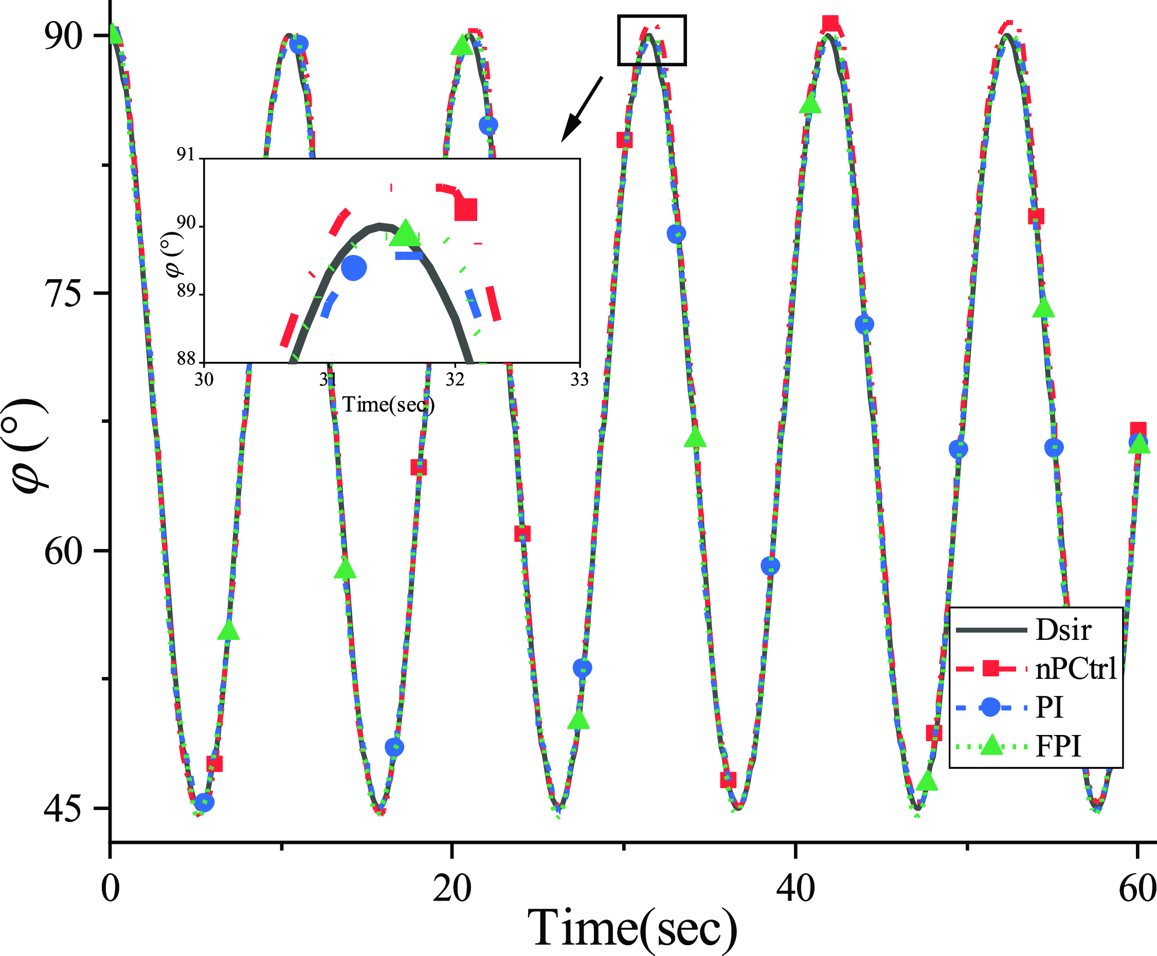
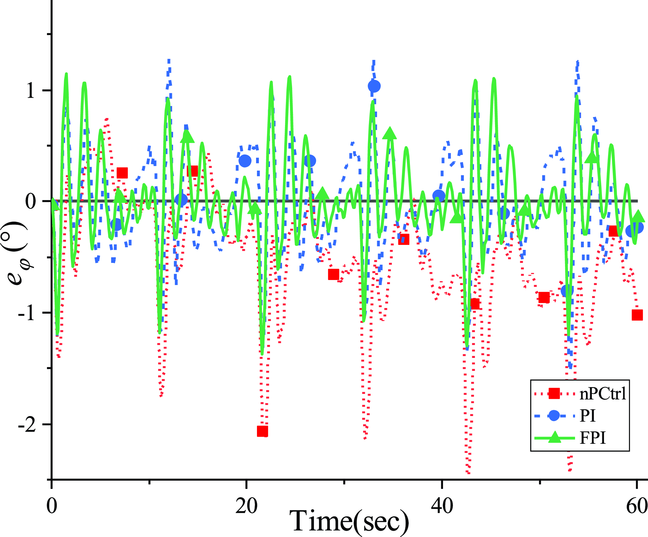
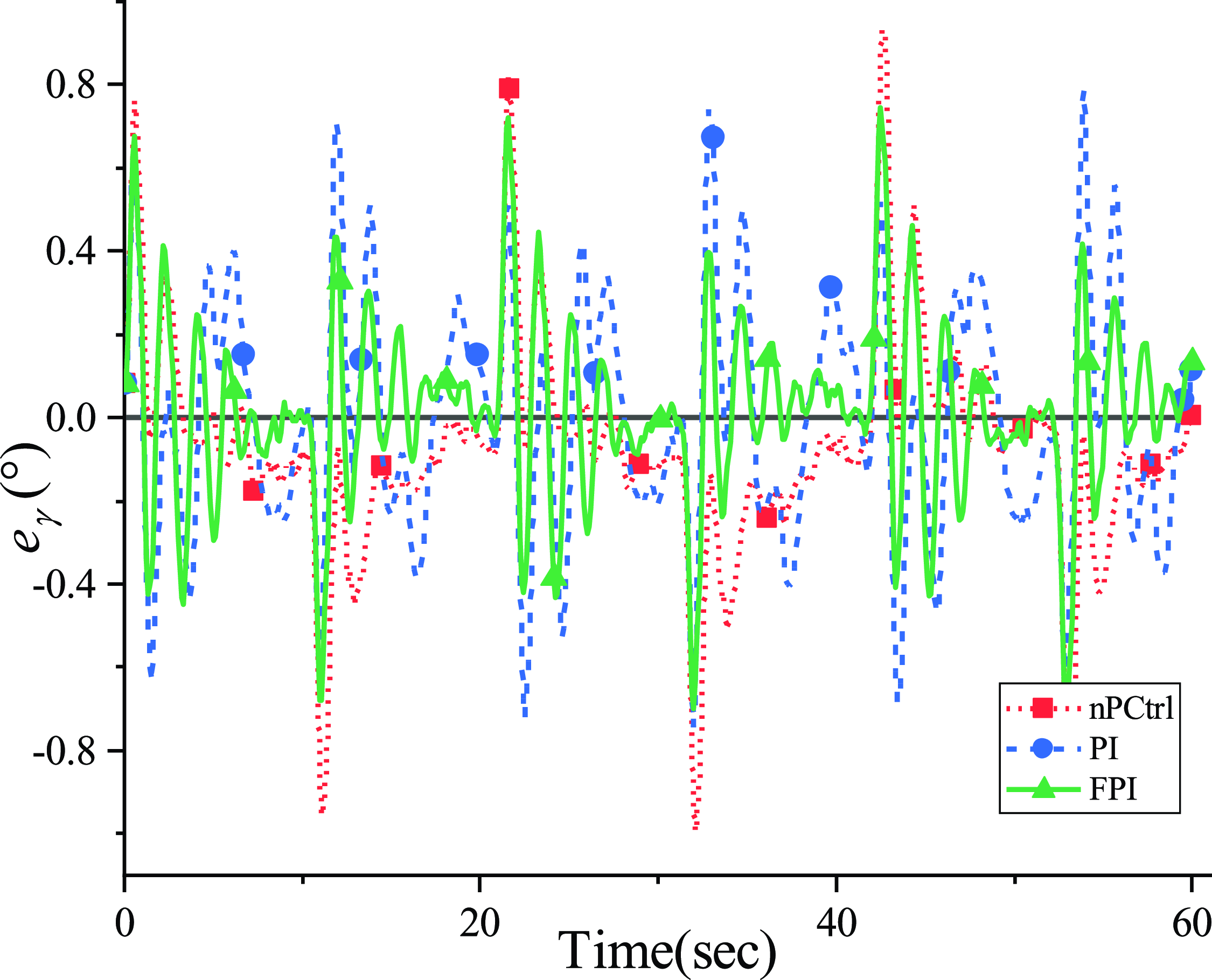
Figures 20 and 21 show the actual running track of the antenna. Figures 22 and 23 are error curves of antenna attitude.
Structural parameters.
Specifications of motor hardware.
Pitch in actual operation.
Azimuth in actual operation.
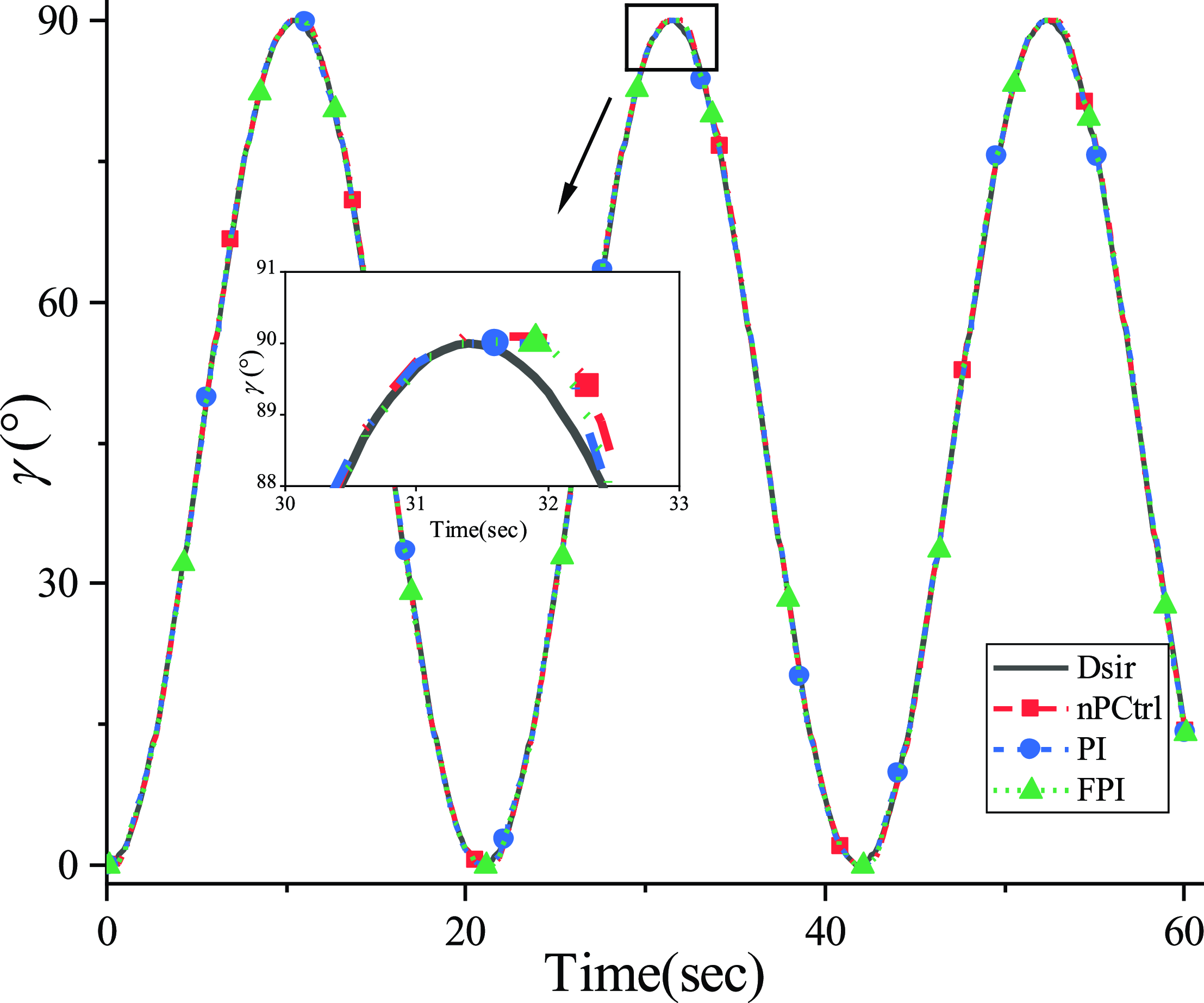
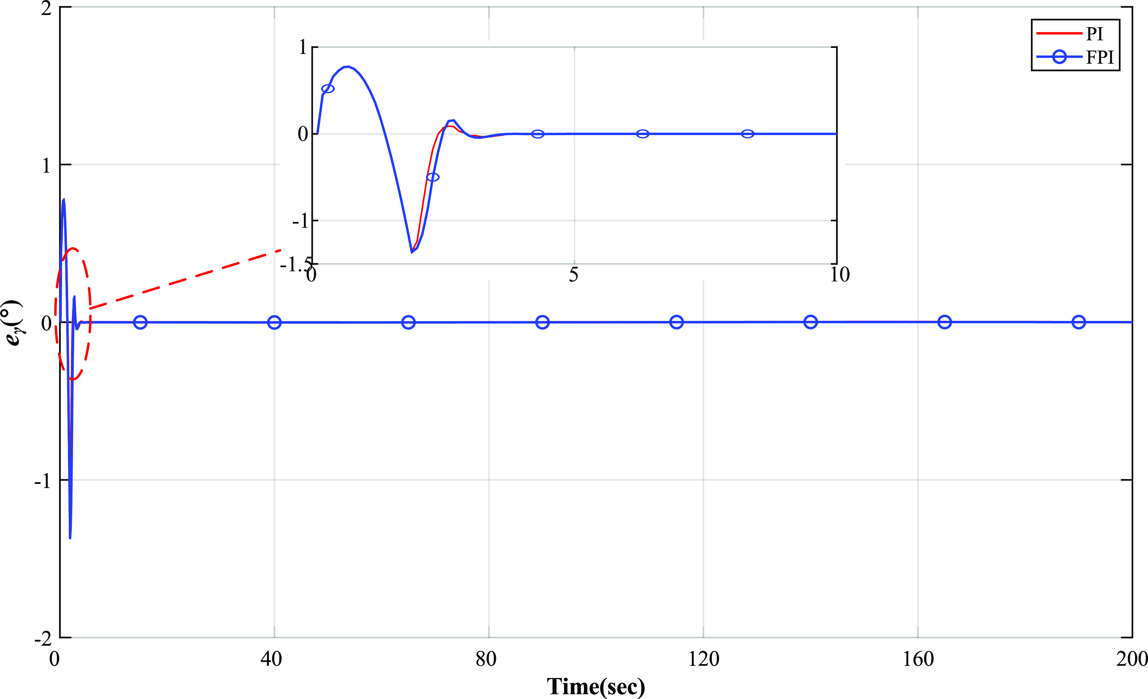
The nPCtrl curve in Figs. 20–23 indicates the tracking result without ordinary position feedback control and only the motor speed is controlled. It can be seen that the antenna platform fails to run along the desired trajectory due to the variation of the friction force and the bearing torque of the motor, resulting in a large attitude error and cumulative error in the pitch direction. After adding the PI controller to the antenna, the attitude error is reduced and the accumulated error in pitch direction is eliminated. The pitch error and azimuth error are subject to [−1.5, 1.3] and [−0.7, 0.8], respectively. It can be observed that under this desired track, the rotation speed of the antenna surface and the speed of the driving motor will become zero and accelerate. Moreover, due to the motion characteristics of the DC motor, the drive sliders have a large speed error when starting, resulting in the attitude error of the antenna surface. It can be inferred from Figs. 22 and 23 that the PI controller fail to track the required trajectory quickly within a period of velocity change.
Pitch error in actual operation.
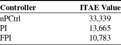
ITAE performance values.
Azimuth error in actual operation.
Parallel robotic antenna pedestal motion demonstration.
Then by adding the FPI controller, the desired trajectory can be tracked relatively quickly, and the pitch error and azimuth error are reduced to the range of [−1.4, 1.1] and [−0.7, 0.7], respectively. It can be inferred from the enlarged part of the actual trajectory in Figs. 20 and 21 that FPI controller can track the target curve with high precision compared with other controllers. In the time domain, ITAE is used to evaluate these controllers, and the ITAE performance values in Table VI show that the FPI controller has the best performance.
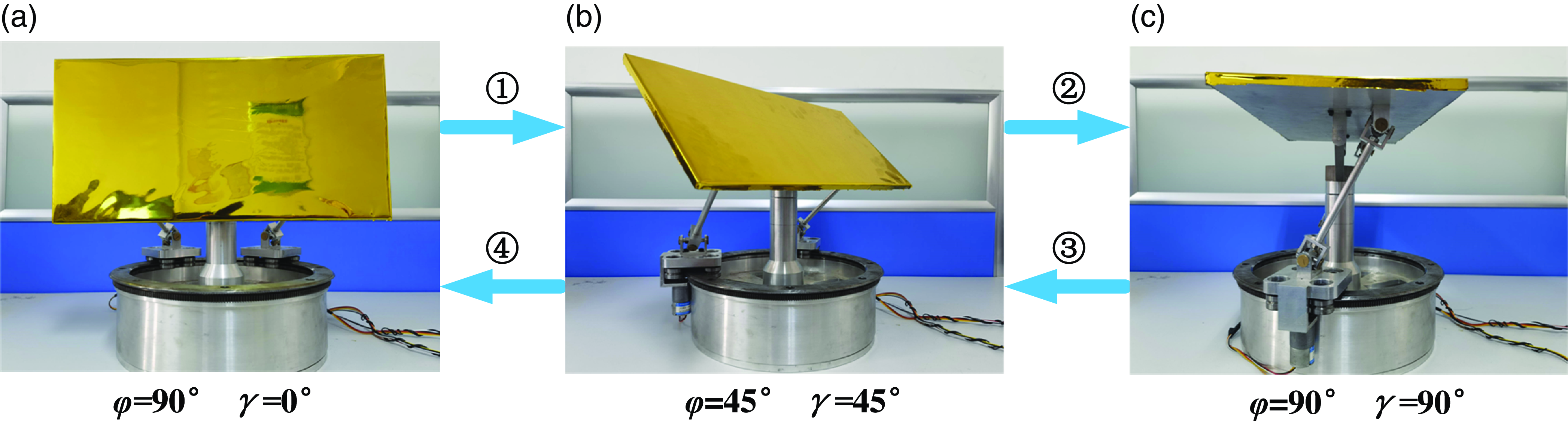
The actual operation of the antenna pedestal is shown in Fig. 24. In the course of movement, the parallel robotic mechanism displays smooth startup and termination, and the attitude error is restricted to a certain range. Together with the final states, prototype experiments validate the proposed FPI control scheme in this paper.
6. Conclusion
This paper introduces the kinematic modeling and motion control of a novel 2-dof parallel robotic antenna pedestal. Due to the nonlinear friction and other uncertain disturbance in the antenna operation process, the trajectory will deviate from the desired one. Therefore, this paper designs the FPI controller based on the position feedback of the drive sliders and the kinematics model of the antenna pedestal. Then, the Simulink simulation model is established, and the parameter coding method of the FPI controller is discussed. The controller parameters are adjusted by simulation experiment, and the actual experiment is carried out on the prototype. The experimental results verify that the tracking performance of this parallel robotic antenna pedestal meets the requirements, and the FPI controller has the advantages of high control accuracy, faster response and improved performance compared with the traditional PID control.
Author contributions
He Shuai and Duan Xuechao conceived and designed the study. Xianpu Qu and Xiao Jiaxuan conducted data gathering. He Shuai and Duan Xuechao wrote the article.
Financial support
This work was supported by the National Key R&D Program of China (No. 2021YFB3900300) and the Fundamental Research Funds for the Central Universities (No. QTZX22160).
Competing interest
The authors declare no Competing interest exist.
Ethical approval
Not applicable.


 Open access

