



Introduction
The rapid development of wireless communications encourages researchers to direct their interest toward the design and fabrication of various antenna prototypes especially after the allocation of 7.5 GHz frequency band from 3.1 to 10.6 GHz for ultra-wide band (UWB) applications by Federal Communications Commission (FCC) [1]. One of the most important components in the wireless communication systems is the UWB antenna since it should achieve necessary requirements such as small size, wide impedance bandwidth, inexpensive cost, stable gain and omnidirectional radiation characteristics [Reference Reddy, Kamma, Mishra and Mukherjee2–Reference Dhasarathan, Sharma, Kapil, Vashist, Patel and Nguyen6]. However, the complexity of each structure of all previously listed UWB antennas in [Reference Reddy, Kamma, Mishra and Mukherjee2–Reference Dhasarathan, Sharma, Kapil, Vashist, Patel and Nguyen6] is not quite small as well as the size is not compact enough to be integrated in microwave communication systems. This is due to the nature of the feeding method which is based on the non-uniplanar structure of ground plane with the radiator.
In order to minimize the aforementioned drawbacks, a coplanar waveguide (CPW) structure is utilized to reduce the complexity of the fabricated model which makes it applicable for integrated microwave systems [Reference Cai, Yang and Cai7]. For further reduction of the overall antenna size, ACS-fed structure is presented since the overall size of this antenna can be reduced to about 50% of the CPW-fed antennas [Reference Liu, Wang and Qin8, Reference Rajkumar and Kommuri9].
The existing narrow-band wireless technologies such as WiMAX (3.3–3.6 GHz) and WLAN (5.15–5.85) can be interfered by the designed UWB antennas and to avoid/mitigate the electromagnetic interference, band-notched characteristics are carried out using various resonators with various locations such as resonators etched from the patch or the ground plane [Reference Ali, Ibrahim and Machac10, Reference Mirmosaei, Afjei, Mehrshahi and Fakharian11], resonators extended form the patch [Reference Salamin, Ali and Zugari12], resonators adjacent to the feed line or the ground plane [Reference Zeng, Zhang, Min and Zhang13, Reference Salamin, Ali and Zugari14].
Multi-input-multi-output (MIMO) technology is used to enhance the channel capacity as well as to solve the multipath fading problem. In the last years, different UWB MIMO antennas have been introduced by researchers. However, as the elements are closely spaced to each other, the mutual coupling effect becomes sturdy and in order to mitigate this effect, various isolation techniques have been reported to reduce the mutual coupling between elements [Reference Ali and Ibrahim15–Reference Wu, Cheung, Li and Yuk17]. CPW and ACS feeding techniques have been utilized in several literature reviews to achieve the compactness of the MIMO antenna with an improved performance [Reference Ojaroudi Parchin, Jahanbakhsh Basherlou, Al-Yasir, Abdulkhaleq, Patwary and Abd-Alhameed18–Reference Dhasarathan, Nguyen, Sharma, Patel, Mittal and Thurai Pandian23]. In [Reference Ojaroudi Parchin, Jahanbakhsh Basherlou, Al-Yasir, Abdulkhaleq, Patwary and Abd-Alhameed18], the antenna structure is composed of eight elements and is fed by CPW for operation at sub 6 GHz 5 G wireless communication. However, the MIMO antenna occupied larger area of 150 × 75 mm2 in addition the isolation is limited by 16 dB over the achieved band. The antenna presented in [Reference Banerjee, Karmakar, Ghatak and Poddar19] comprises of two CPW-fed monopole radiators with an improved isolation and compact size, but the antenna structure is complicated due to the use of Minkowski fractal geometry in the ground plane and the achieved value of ECC is significant. Two monopole MIMO antenna with hexagonal radiators with two arc-shaped stubs connected together in the ground, is introduced in [Reference Mathur and Dwari20]. The antenna provided an acceptable level of isolation not exceeding 15 dB with a larger value of ECC although the two radiators are mounted on the substrate in anti-parallel configuration. A quad port UWB MIMO antenna composed of four orthogonal radiators is proposed in [Reference Kunal, Ashwani, Kanaujia Binod, Dwari and Kumar21]. The antenna succeeded to provide an insertion loss <−20 dB over the entire range of UWB communications, but it failed to achieve the expected compactness in size as well as the smaller values of ECC. In [Reference Ibrahim, Abdalla and Hu22], the performance UWB MIMO is investigated using two ACS-fed quarter elliptical ring radiators, and it achieved a moderate level of isolation although the spacing between elements is larger enough.
In this paper, highly isolated ACS-fed MIMO antenna with four identical semi-elliptical elements is designed to cover the unlicensed UWB band from 3.1 to 10.6 GHz. This antenna is designed on low-cost substrate FR-4 with simple structure, compact size and high isolation between the MIMO elements without using extra decoupling structures. The proposed MIMO antenna is simulated, fabricated, and tested to validate its UWB behavior with the band notched characteristics at WiMAX frequency range, by measuring its scattering parameters. Moreover, the radiation characteristics are investigated to ensure the omnidirectional radiation properties of the suggested antenna and the gain is nearly constant over the entire achieved band for UWB communications. The MIMO parameters such as ECC, DG, CCL, and multiplexing efficiency are also investigated to assure the diversity performance of the suggested UWB MIMO antenna.
Single element antenna design
The single element of the suggested MIMO antenna is investigated in this section. Figure 1 demonstrates the configuration of the UWB antenna. The antenna consists of half elliptical-shaped element fed by ACS configuration. The antenna first is designed using complete CPW configuration and elliptical-shaped radiator as first step in the antenna design. Second, the antenna radiator and feed line is reduced to half to reduce the overall size of the antenna. The ACS feeding configuration as function of width of the transmission line (3 mm) and the gap (0.3 mm) between the ground plane and the strip width is optimized to fulfill the required 50 Ω line impedance. The proposed antenna is designed to support UWB communication bands from 3.1 GHz up to 10.6 GHz. To produce the desired frequency band, the ground plane has partial ground with curvature around its end as shown in Fig. 1. The suggested antenna has wide-band operation to cover the entire frequency band. However, there are other systems operated in frequency bands within the proposed UWB frequency bands. Therefore, we need the antenna to block the radiation at these frequency bands. One of these systems is WIMAX application from 3.3 to 3.9 GHz. Therefore, we designed the simple stub as shown in Fig. 1 to introduce frequency band notched at the WIMAX bands. The length of the stub is designed to fulfill the equation below

Proposed single element UWB antenna with dimensions (a) 2D configuration, (b) 3D configuration.

L is the total stub length, c is the speed of light, ɛr is the relative permittivity of the substrate, f notch is the desired frequency of the notch (3.5 GHz) and λg is the guided wavelength.
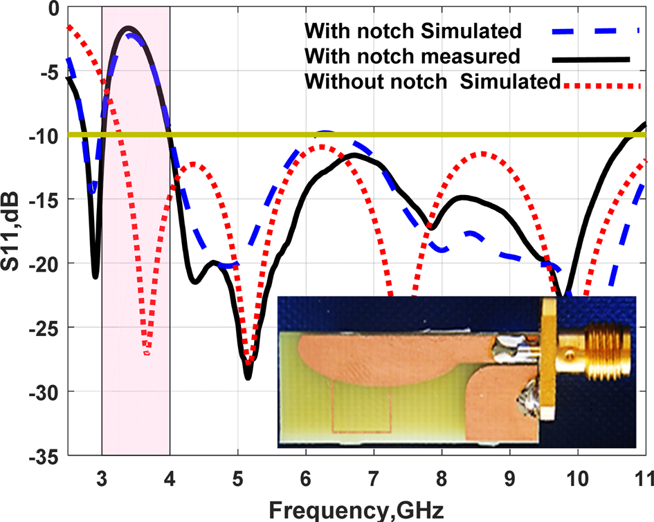
We utilized FR4 material as substrate with relative permittivity, tan δ and height of 4.4, 0.02 and 1.6 mm, respectively. The proposed single antenna is fabricated and measured using R&S ZVB 20 vector network analyzer (VNA) as illustrated in Fig. 2 to validate the simulated results. The overall antenna size equals 28 mm × 11.5 mm2. The S 11 results of the single antenna with and without stub are shown in Fig. 2. The antenna has bandwidth from 2.7 up to 11 GHz with S 11 lower than −10 dB instead of the frequency band from 3 to 4 GHz (the WIMAX band). Finally, the simulated and measured results have approximately the same trend which confirms the good results.
The S11 performance of the ACS-fed antenna.
2-element MIMO antenna configurations
The 2-element UWB MIMO antennas are illustrated in this section. The first step in designing 2-element MIMO antennas is studying the orientation of the elements which produces the desired high isolation between them. Figure 3 illustrates the three configurations which are used in the antenna design. The first configuration (antenna 1) is shown in Fig. 3(a), the two elements have 90o between them (orthogonally orientation) with space equals 15 mm (0.135λ 0 at 2.7 GHz) between the edges of the two antennas. The second configuration (antenna 2) is illustrated in Fig. 3(b). The two elements have 180° between them and put in opposite orientation as compared with the first element with the same space between the edges as antenna 1. Finally, the third configuration (antenna 3) has the same space between the antenna edges as shown in Fig. 3(c). The two elements have 0° between them and put at the same line with the first element (side by side). These are the possible three orientations which can be used using two elements.
The configurations of 2-elements MIMO antenna (a) antenna 1, (b) antenna 2, (c) antenna 3.

The simulated S 21 of the three antenna configurations are demonstrated in Fig. 4. It is apparent that the antenna 2 (opposite orientation) has lower mutual coupling between elements. The mutual coupling is less than −20 dB within the operated frequency band. The antenna 1 (orthogonally oriented) has mutual coupling lower than −17 dB within the entire frequency band. Furthermore, the antenna 3 has mutual coupling less than −15 dB within the achieved frequency band. Finally, it can be deducted that the two orientations (90° and 180°) have low mutual coupling than the side by side orientation which leads to good MIMO performance outcomes.
The simulated S 21 performance of the 2-element MIMO antennas.

Antenna 1 is chosen for fabrication and validation as shown in Fig. 5. The S 11 and S 21 of the two elements orthogonally oriented MIMO antenna are shown in Fig. 5. It is noticed that the fabricated antenna has good results when compared with the simulated one. The measured S 11 is lower than −10 dB with bandwidth extended from 2.7 up to 11 GHz except the band from 3 up to 4 GHz (WiMAX band). The measured S 21 is less than −18 dB through the worked frequency band with good performance when compared to the simulated results.
The S 11, S 21 performance (measured and simulated) of the MIMO antenna 1.

Proposed 4-element UWB MIMO antenna configurations and its results
UWB MIMO antenna configurations
Based on the previous discussion, the 4-element antenna is arranged as depicted in Fig. 6. We combined the two orientations of previous configuration of antenna 1 and 2. The antenna element at port 2 is oriented orthogonally on antenna at port 1 and 3 and oriented in the opposite direction with the antenna at port 4. The spaces between the edges of the antenna at port 1 and antenna at port 2, antenna at port 3 and antenna at port 4 equal 15 mm ((0.135λ 0 at 2.7 GHz)), 29 mm (0.26λ 0 at 2.7 GHz) and 11 mm (0.099λ 0 at 2.7 GHz), respectively, as shown in Fig. 6(a).
The configurations of suggested 4-element MIMO antenna (a) 3-D configuration with dimensions (b) fabricated photograph.

Scattering parameters and current distribution results
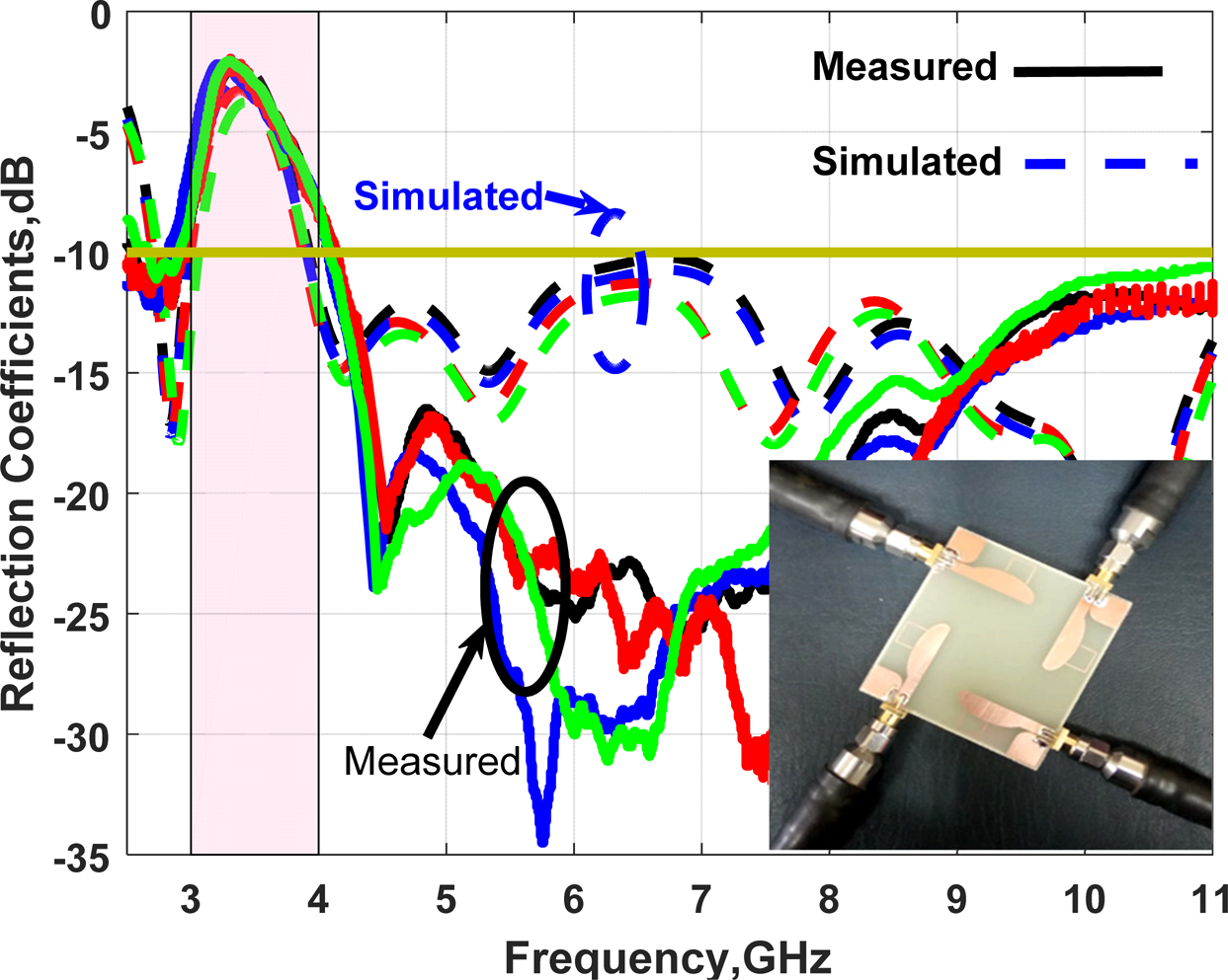
The suggested 4-element MIMO antenna with band notched behavior is fabricated as shown in Fig. 6(b) using R&S ZVB 20 four ports VNA to validate the antenna design by measuring its S-parameters performance as shown in Figs 7 and 8. Figure 7 displays the simulated and measured return loss results (S 11, S 22, S 33, S 44) using 4-ports VNA as shown in Fig. 7. It is seen from measuring results that, first the antenna is worked at frequency bands from 2.7 up to 11 GHz (UWB range) with good reflection coefficients performance lower than −10 dB at the four ports excluding the WiMAX band from 3 up to 4 GHz (the band notched region). Also, Fig. 8 presents the measured and simulated coupling coefficients (S 21, S 31, S 41, and S 42). The measured results have mutual coupling lower than −20, −24, −28, −27 dB between ports 1, 2, ports 1, 4, ports 1, 3 and ports 2, 4. The reason for the high isolation is the best choice of the antenna orientations as discussed before.
The (S 11, S 22, S 33, S 44) performance (measured and simulated) of the suggested 4-element MIMO antenna.
The coupling coefficients results (measured and simulated) of the proposed 4-element MIMO antenna (a) S 21, S 31, (b) S 41, S 42.
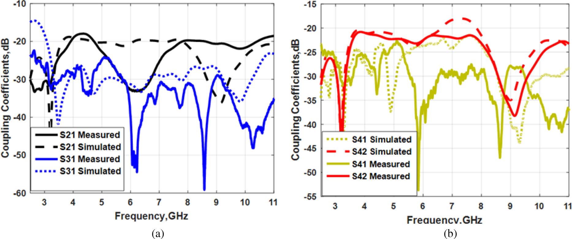
The measured results have good trend with the simulated ones. Nevertheless, the measured results have a little shift with the simulated results and this is due to the fabrication tolerance and soldering process.
Figure 9 illustrates the surface current behavior of the 4-element antenna at 3.5 GHz (the center band of the notch) and at 8 GHz. The current distribution is studied to show the behavior of the MIMO antenna at different frequency bands. First at 3.5 GHz as shown in Fig. 9(a), it is seen that the current is collected around the stub and prevented the antenna from radiation at this frequency band. Second at 8 GHz, the current is distributed along the radiator (ordinary radiation), also there is very weak current which is transferred to other antenna elements which means the high isolation between the four elements and this is actually based on the antenna orientations without using any decoupling structures.
The surface current distributions of the suggested 4-element MIMO antenna (a) at 3.5 GHz, (b) at 8 GHz.

Radiation pattern results
In order to show the pattern diversity of the suggested MIMO antenna, the simulated 3-D pattern is investigated at different frequency bands as shown in Fig. 10. The desired port is excited and the other ports are terminated with matched loads as depicted in Fig. 10. It is noticed there is a progressive phase difference of 90° between each two successive ports that confirms the suitability of our proposed configuration to achieve the desired polarization diversity which in turn will improve the MIMO performance.
The 3-D radiation patterns of the suggested 4-element MIMO antenna (a) at 3.5 GHz, (b) at 8 GHz.

The simulated x−z plane and y−z plane co-pol and X-pol radiation patterns at 6.5 and 9.5 GHz of port 1 are shown in Fig. 11. It is clear that the radiation pattern of the x−z plane is semi-omnidirectional with cross polarization lower than −15 dB. However, the radiation pattern of the y−z plane is bidirectional with cross polarization lower than −12 dB. The co-polarization has a higher and reasonable value than the cross polarization in both planes at 6.5 and 9.5 GHz.
The co and cross polarization radiation pattern performance results of the suggested 4-element MIMO antenna at port 1 (a) x−z plane, (b) y−z plane.

The peak gain and efficiency of the proposed MIMO antenna at port 1 is depicted in Fig. 12. The antenna has an average gain and efficiency around 3.5 dBi and 85% within the entire frequency bands from 4.1 up to 11 GHz. However, the antenna has lower gain and efficiency at the notched band around −5 dBi and 18%, respectively. The normalized radiation patterns of the suggested 4-elements MIMO antenna is measured inside anechoic chamber at 3.5, 6.5 and 9.5 GHz in three planes (x−z, y−z and x−y). In the measuring setup; we excite port 1 and port 2 independently. When port 1 is excited, the other ports are terminated with matched load and vice versa.
The peak gain and efficiency performance results of the proposed 4-element MIMO antenna at port 1.

It is obvious from Figs 13 and 14 that, first, the pattern has semi omnidirectional at both x−z and x−y planes at both two ports with 90o rotation between them. Second, the radiation patterns at y−z plane are the same with the bidirectional shape when any of the two ports is excited. Third, the simulated and the measured results performance have the same trend with small shift between them because of the ACS feeding structure and measurements setup. Finally, it can be concluded that the proposed MIMO antenna produces the desired polarization diversity.
The radiation pattern performance results of the suggested 4-element MIMO antenna at port 1 (a) at 3.5 GHz, (b) at 6.5 GHz, (c) at 9.5 GHz.

The radiation pattern performance results of the suggested 4-element MIMO antenna at port 2 (a) at 3.5 GHz, (b) at 6.5 GHz,, (c) at 9.5 GHz.

MIMO performance results and discussions
In this part, four parameters such as (the envelope correlation coefficient (ECC), the diversity gain (DG), the channel capacity loss (CCL) and the multiplexing efficiency (η mux)) are studied and investigated to judge the diversity feature of the suggested MIMO systems.
The ECC
The first important parameter to evaluate the MIMO system is ECC. The ECC is defined as the correlation between the elements in MIMO system. Higher MIMO performance means lower ECC between elements. There are two equations that are used to extract the ECC parameter. The first one is extracted from the S-parameters assuming the environment with uniform multipath as [Reference Blanch, Romeu and Corbella24, Reference Abdalla and Ibrahim25]

The second one is extracted from the radiation patterns results as [Reference Blanch, Romeu and Corbella24]

where Fi(θ, Ф) is the radiation pattern field with the excitation at port 1 and ● is the Hermitian product.
Based on Ref. [Reference Mao and Chu26], the agreeable limits of ECC is lower than 0.5. The ECC results (simulated and measured) between (ports (1,2), (1,3), (1,4), and (2,4)) are extracted from the previous two equations and displayed in Fig. 15. The value of the ECC at the frequency band (4–11 GHz) is lower than 0.0002, 0.0004 and 0.008 extracted from S- parameters, the measured results, and the radiation patterns parameters, respectively. However, the obtained values at the notched frequency band (3–4 GHz) are 0.15, 0.03, and 0.18, respectively. The lower values of the ECC between the antenna elements mean good MIMO features.
The ECC performance of the suggested 4-element MIMO antenna (a) from S-parameter simulation, (b) from S-parameters measured, (c) from radiation patterns simulation.

Diversity gain (DG)
The second parameter to judge the behavior of MIMO systems is DG which is linked to ECC by the following equation [Reference Rosengren and Kildal27]:

The DG results (measured and simulated) between (ports (1,2), (1,3), (1,4), and (2,4)) of suggested MIMO antenna are extracted and shown in Fig. 16. The DG equals around 9.97, 9.96 dB extracted from S-parameters (Fig. 16(a)) and the measured results (Fig. 16(b)), respectively within the frequency band (4–11 GHz), while the achieved values in the notched frequency band (3–4 GHz) are 9.1 and 9.85 dB for both simulation and measurement cases, respectively.
The DG performance of the suggested 4-element MIMO antenna (a) from S-parameter simulation, (b) from S-parameters measured.

The CCL
The third parameter to estimate the MIMO performance is CCL (bit/s/Hz). The channel capacity is considered the rate of data which can be transferred over the communication channel [Reference Choukiker, Sharma and Behera28]. The CCL can be determined using correlation coefficient matrix and can be calculated using equations (5), (6) with agreeable value lower than 0.4 bit/s/Hz [Reference Choukiker, Sharma and Behera28, Reference Shin and Lee29].


and

The CCL results (simulated and measured) between (ports (1,2), (1,3), (1,4), and (2,4)) are calculated using equations (5), (6) and illustrated in Fig. 17. The value of the CCL at frequency band from 4 GHz up to 10.5 GHz is lower than 0.4 bit/s/Hz except the notched frequency band.
The CCL performance of the suggested 4-element MIMO antenna (a) from S-parameter simulation, (b) from S-parameters measured.

Multiplexing efficiency (η mux)
The last parameter used for MIMO evaluation is η mux. The η mux is the ratio between the power of the real antenna to the power of ideal antenna [Reference Tian, Lau and Ying30]. The η mux can be extracted assuming uniform environment and high signal to noise ratio (SNR) as [Reference Tian, Lau and Ying30]

The η 1, η 2 are the total efficiency of the two real antenna elements and r is the magnitude of complex correlation coefficients between the antenna elements. The simulated η mux between (ports (1,2), (1,3), (1,4), and (2,4)) are calculated using equations (7) and shown in Fig. 18. The η mux equals around −1 dB within the band from 4 to 11 GHz, whereas the minimum value equals −8 dB within the notched frequency band.
The simulated multiplexing efficiency performance of the suggested 4-element MIMO antenna.

Finally, to compare our study with recently published studies, Table 1 is constructed as illustrated. Table 1 shows that our antenna has compact size and provides high isolation with significant MIMO performance which permits our antenna to be utilized in UWB communications.
Comparison between the suggested antenna and recently reported antennas

Conclusion
A compact size 4-element band-notched UWB MIMO antenna has been simulated, fabricated and experimentally checked. Four radiators with four ACS-fed have been printed on FR4 substrate of size 48 × 52 × 1.6 mm3. The bandwidth from 2.7 to 11 GHz with an improved isolation (>20 dB) has been accomplished with a band stop behavior from 3 to 4 GHz to prevent interference with WiMAX applications. Moreover, radiation pattern is acceptably omnidirectional with realized gain and radiation efficiency of average values of 3.5 dBi, 85% over the UWB range, respectively. Good diversity performance has been investigated as the ECC <0.0004, the CCL <0.4 bit/s/Hz, and η mux ≈ −1 dB within the accomplished band. It is worth saying that the simulated and measured results have been almost resembled for both impedance and radiation characteristics making the suggested MIMO antenna good candidate for UWB wireless technologies.
 Ahmed A. Ibrahim was born in 1986. He received the B.Sc. degree, and M.Sc., Ph.D. in electrical engineering from the Electronic and Communication Engineering Department, Minia University, Elminia, Egypt in 2007, 2011 and 2014, respectively. He is now an associate professor in Electrical Engineering Department in Faculty of Engineering, Minia University. He has been a visiting professor in University Pierre and Marie Curie, Sorbonne University, Paris VI, France for 7 months and Otto-von-Guericke-Universität Magdeburg Germany for 6 months. He has published more than 70 peer-reviewed journals and conference papers. His research has focused on miniaturized multiband antennas/wideband, microwave/millimeter components. Also, his research includes MIMO antennas and energy harvesting systems. Dr. Ahmed A. Ibrahim is senior member of the IEEE and senior member in URSI is also a member in the national committee of radio science in Egypt.
 Wael A. E. Ali was born in 1982. He received his B.Sc. and M.Sc. in electronics and communications engineering from Arab Academy for Science, Technology and Maritime Transport (AASTMT), Alexandria, Egypt in 2004 and 2007, respectively. He obtained his Ph.D. in electronics and communications engineering from Alexandria University, Alexandria, Egypt in 2012. He is currently an associate professor at Arab Academy for Science, Technology and Maritime Transport (AASTMT), Alexandria, Egypt. He has published more than 65 peer-reviewed journals and conference papers. His research interests include smart antennas, microstrip antennas, microwave filters, metamaterials, millimetric-wave antennas and MIMO antennas for various wireless communications applications.



