

I. INTRODUCTION
The IEEE 802.15.4a standard is primarily designed to provide accurate range estimation between communicating devices for low rate wireless personal area network (LR-WPAN) applications [Reference Karapistoli, Pavlidou, Gragopoulos and Tsetsinas1]. The standard is based on the impulse radio ultra-wideband (IR-UWB) technology where very short pulses measured in 2 ns are transmitted. In this standard, a ranging support is provided by series of ternary preamble sequences with perfect autocorrelation properties [Reference Kwok, Chin and Peng2]. IEEE 802.15.4a supports different receiver architectures such as coherent receivers and energy detectors [Reference D'Amico, Mengali and Taponecco3]. Coherent receivers operate at a high sampling frequency and use complex algorithms, which are inappropriate for some applications. Energy detection (ED) receivers work at a sub-Nyquist sampling frequency and use low complex algorithms that make them low cost and low-power consumption which are appropriate for many applications [4].
One key issue for IEEE 802.15.4a standard receivers is the accurate ranging with the time-of-flight (TOF) or time-of-arrival (TOA) technique [4]. The TOA estimation problem is equivalent in search of the first arrived path. ED receivers calculate energy blocks by squaring the received signal. The first energy block passes predefined threshold level corresponds to the first arrived path. Numerous approaches have been proposed in the literature for direct path detection algorithms using the characteristics of the IEEE 802.15.4a preamble. In [Reference Lei, Chin and Kwok5], a new pulse-based UWB system is proposed with low-power ranging supporting both power efficient energy detectors and coherent detectors. An iterative algorithm based on multi-scale sliding correlation window is proposed in [Reference Dazhong, Zhengding and Xiong6]. In [Reference Geiger7], the ranging capabilities of the IEEE 802.15.4a standard with ternary preamble sequences are analyzed. In [Reference Geiger, Gigl and Witrisal8], a single ED receiver is employed for channel estimation and ranging whose sampling rate is shifted with respect to the pulse repetition frequency.
In this paper, we propose a novel ED receiver architecture combined with TOA estimation algorithm, which is suitable for IEEE 802.15.4a standard. The architecture is based on double overlapping integrators and a sliding correlator block. This block, ensures coding gain providing the estimate of power delay profile (PDP) with accuracy [Reference Geiger7] which is used for TOA estimation. The improvement of this estimation, based on PDP samples interpolation, is proposed and the architecture is validated on signals measured in line-of-sight (LOS) and non-line-of-sight (NLOS) multipath environments. The remainder of this paper is organized as follows. In Section II, the signal model is given. In Section III, the proposed receiver architecture is presented. In Section IV, the TOA estimation algorithm is described. Section V is devoted to experimental setup and results. Section VI concludes this paper.
II. SIGNAL MODEL
In the IEEE 802.15.4a standard [4, Reference Geiger7], the transmitted signal within the synchronization (SYNC) field is given by
 $$x(t) = \mathop \sum \limits_{k = 0}^{N_{sync} - 1} \mathop \sum \limits_{l = 0}^{N_c - 1} C_i(l)g(t - lT_cL - kT_{psym}),$$
where N sync ∈ {16, 64, 1024, 4096} is the number of preamble symbols. C i and N c denote the ternary code sequences, i.e., {−1, 0, +1}, and the code length, respectively. k is the preamble symbol index and L ∈ {4, 16, 64} defines the spreading factor according to channel excess delay [4]. T c denotes the chip duration, T psym = LT cN c is the duration of each preamble symbol and g(t) is written as follows
 $$g(t) = p(t)\cos (2\pi f_ct)$$
with f c is the center frequency of g(t) and p(t) is a root-raised cosine filtered pulse with duration of 2 ns and a roll-off factor of 0.6 [4]. Now, the duration of the transmitted signal x(t) can be expressed as
 $$T_{sync} = LT_cN_cN_{sync}.$$
The received signal in multipath channel can be expressed as
 $$r(t) = \mathop \sum \limits_{k = 1}^K \alpha _kx(t - \tau _k) + n(t),$$
where {α k, τ k} are, respectively, the attenuation and delay of kth path, k is the number of multipath components and n(t) is an additive noise. The TOA of the received signal is given by τ toa = τ 1, which is identified by the first arriving path.
III. PROPOSED ENERGY DETECTION RECEIVER STRUCTURE
The proposed ED receiver structure operates as follows: the signal r(t) at the receiver antenna is amplified by a low noise amplifier (LNA) and passes through a band-pass filter (BPF). Then the signal is processed with a square law device, and feeds two overlapping integrators as indicated in Fig. 1. The first integrator performs the integration between 2nT b and 2(n + 1)T b, and the second between (2n + 1)T b and (2n + 3)T b. The integration duration is 2T b and the overlapping duration is T b. The outputs z 1(n) and z 2(n) of the integrators are combined and converted by the analog-to-digital converter (ADC) to form the samples z ov(n). These samples are fed into a sliding correlator block already detailed in Fig. 1 [Reference Geiger7].
Proposed ED receiver structure.
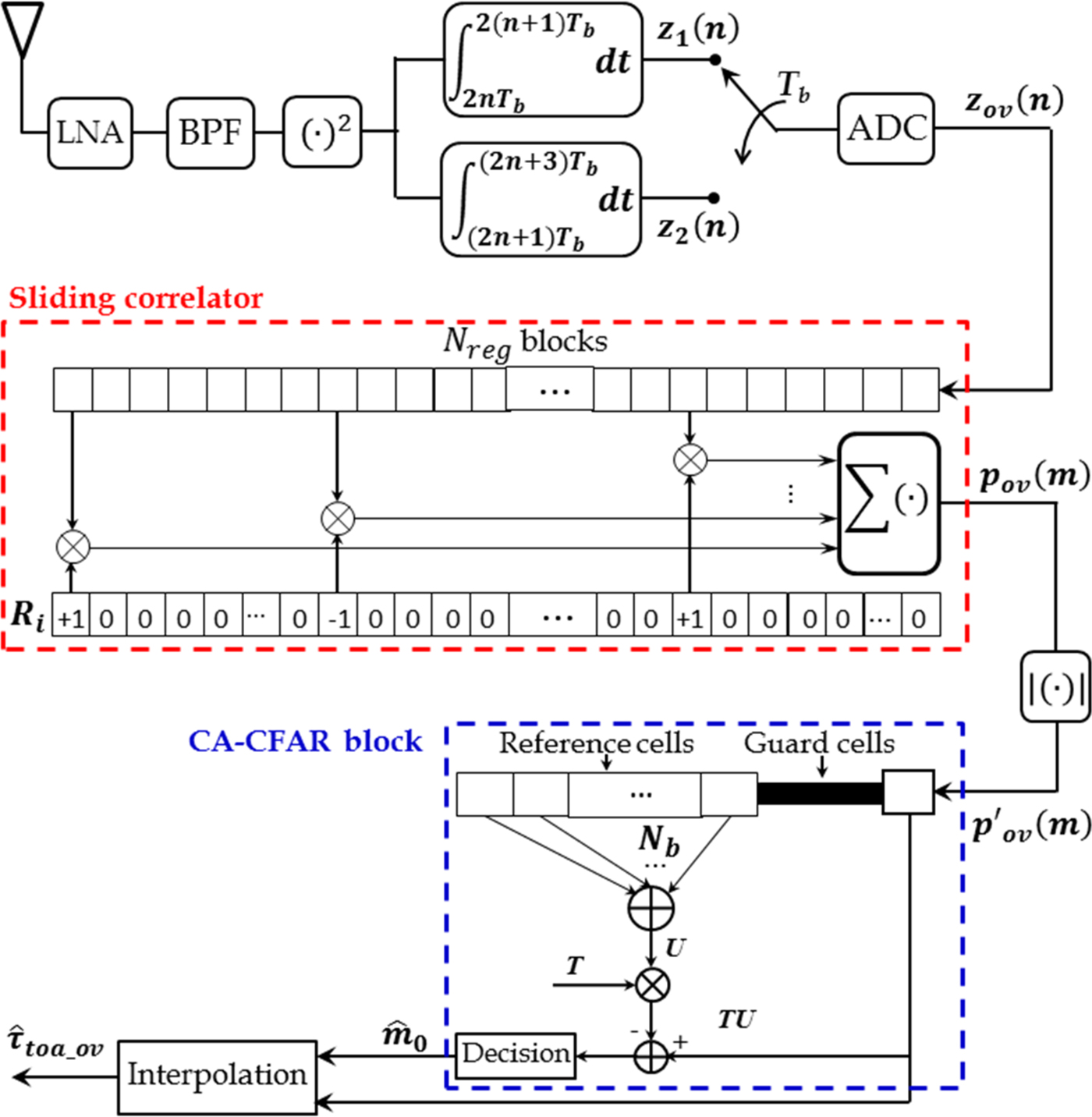
As shown in Fig. 1, the sliding window correlator carries out the correlation between the energy samples z ov(n) and the reference preamble sequence R i = (2|C i| −1) ⊗ δ L. Where (2|C i| −1) is the sequence obtained by the converting the ternary sequence to binary sequence by mapping +1/−1 to +1 and 0 to −1 [Reference Lei, Chin and Kwok5], ⊗ denotes the Kronecker product and the spreading sequence δ L defines as a unit vector with a one at the first position and length L [Reference Geiger7]. The output of the sliding correlator block p ov(m) can be considered as an estimate of the PDP which is given by [Reference Geiger7]
 $$p_{ov}(m) = \mathop \sum \limits_{n = 0}^{N_{reg} - 1} R_i(n)z_{ov}(n - m)$$
where N reg = LT cN c/T b is the number of energy blocks per preamble symbol. R i(n) and z ov(n − m) are the reference preamble sequence and the energy samples, respectively.
IV. TIME OF ARRIVAL ESTIMATION ALGORITHM
A) CA-CFAR algorithm
With reference to Fig. 1, after the sliding correlator, the PDP estimate p ov(m) is fed into an absolute value block and we note  ${p}^{\prime}_{ov}(m) = \vert p_{ov}(m)\vert$. A cell averaging constant false alarm rate (CA-CFAR) [Reference Maali, Mesloub, Djeddou, Mimoun, Baudoin and Ouldali9] is then employed to estimate the TOA, where the samples ${p}^{\prime}_{ov}(m)$ (cells) are sent serially in a shift register of length N b + 1. The N b + 1 samples correspond to the reference cells ${p}^{\prime}_{ov}(i)\; (i = m + 1, \ldots, N_b + m)$ and the test cell ${p}^{\prime}_{ov}(m)$.
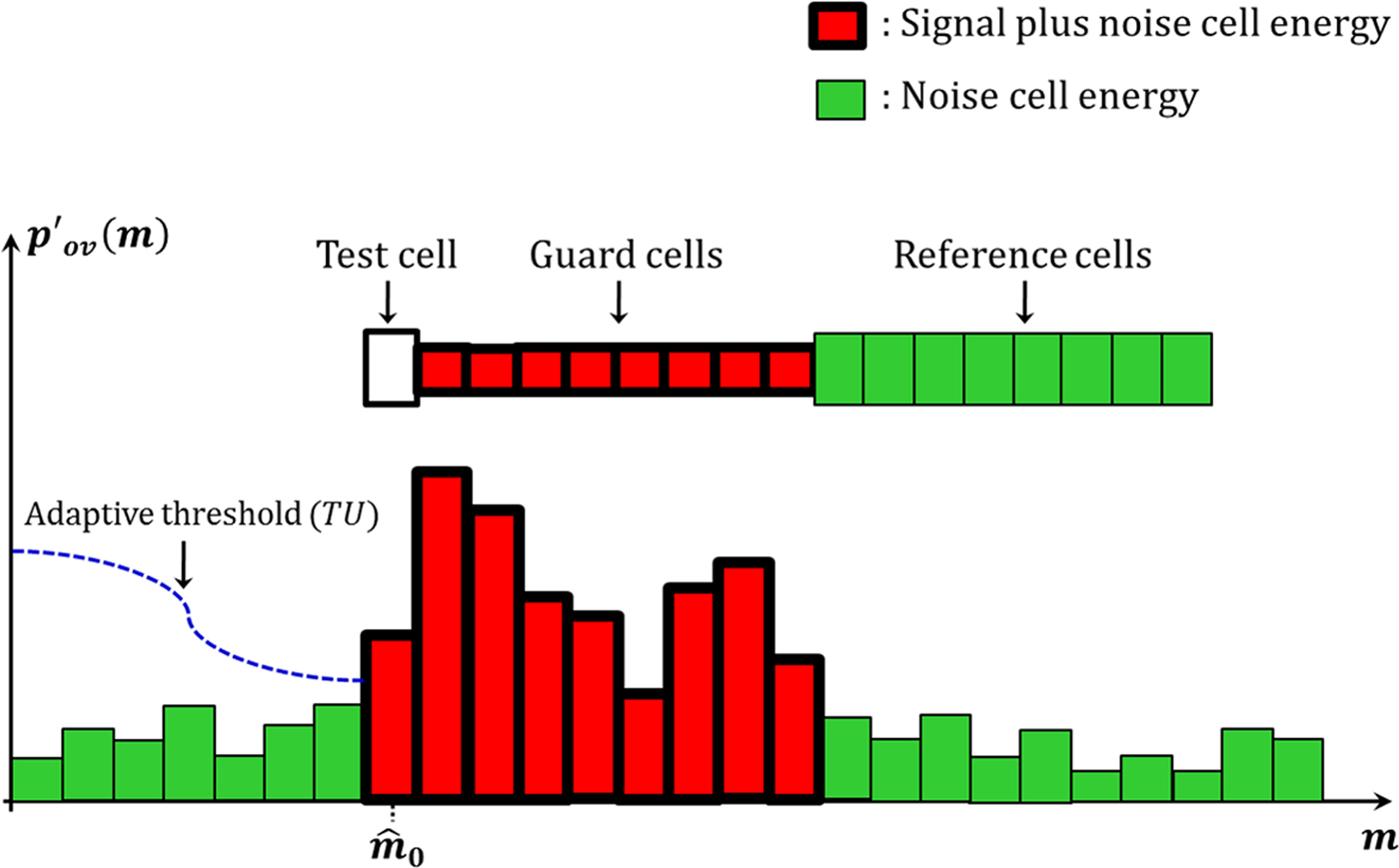
Each energy cell or cell under test (CUT)  ${p}^{\prime}_{ov}(m)$ is compared to an adaptive threshold (TU), which is formed by the sum of other cells subsequently multiplied by a threshold multiplier T. The first cell exceeding this adaptive threshold is considered a leading edge cell as illustrated in Fig. 2. Then, the index of the first cell exceeding the adaptive threshold (TU) is given by
 $$\hat m_0 = \mathop {\min} \limits_m \left\{ {m{\rm \vert} {{p}^{\prime}\!\!}_{ov}(m) \gt TU} \right\},$$
where  $U = \sum\nolimits_{i = m + 1}^{N_b + m} {{{p}^{\prime}\!\!}_{ov}(i)} $ is the sum of energy cells, excluding guard cells. Generally, the guard cells duration is chosen larger or equal to the channel mean delay [Reference Maali, Mesloub, Djeddou, Mimoun, Baudoin and Ouldali9].
Illustration of the adaptive threshold CA-CFAR algorithm.
B) Interpolation TOA estimation
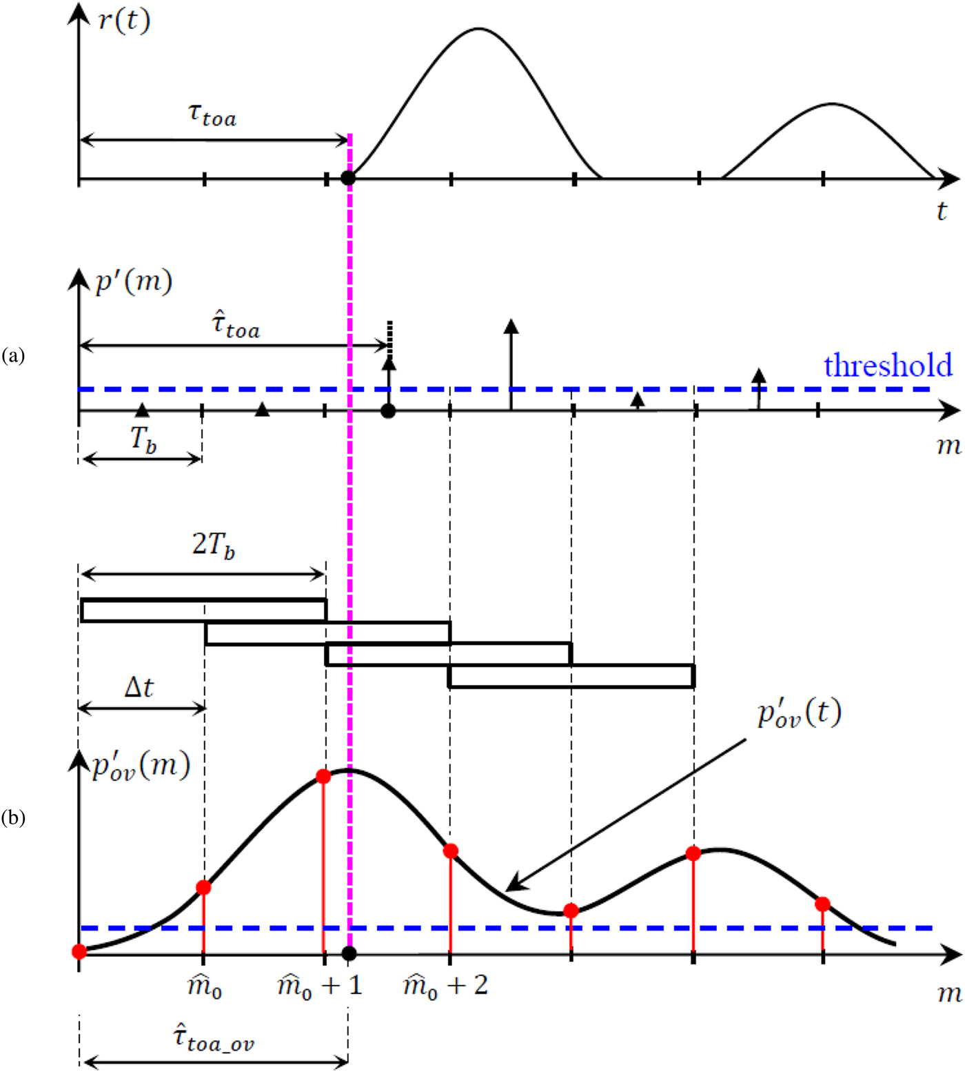
In the conventional ED receiver based on a single-integrator, the sampling is carried out in the middle of the integration windows, which are separated by the sampling interval T b as indicated in Fig. 3(a) (where p′(m) is determined in conventional ED receiver case). In our approach, the double overlapping integrators are equivalent to a single integrator with integration window shifting method, and the sampling is carried out at the beginning of the integration windows. For illustration, we suppose the following assumptions: the chip duration T c = 2T b, noise-free case and the first and the second arriving paths are separated by an interval higher than T c. When the shifting duration Δt is very small (Δt << T b), the samples of  ${p}^{\prime}_{ov}(m)$ will approximate the continues function ${p}^{\prime}_{ov}(t)$ as shown in Fig. 3(b). Therefore, the time instant of the first peak of ${p}^{\prime}_{ov}(t)$ corresponds to the TOA. Hence, the samples close to the first peak of ${p}^{\prime}_{ov}(t)$ can be used to provide more information on TOA. In our approach, Δt = T b and T c = 2T b as shown in Fig. 3(b), and there is maximally three dominant samples close to the first peak. These samples exceeding the adaptive threshold (TU) can be used to accurate TOA estimation with simplified maximum-likelihood method expressed as [4]
 $$\hat \tau _{toa\_ov} = \displaystyle{{{\bi t}^T{\bi h}} \over {1^T{\bi h}}}$$
where superscript “T” denotes transpose,  ${\bi t} = [\hat m_0T_b (\hat m_0 + 1)T_b\; \; (\hat m_0 + 2)T_b]^T$, 1T = [111] and ${\bi h} = [{p}^{\prime}_{ov}(\hat m_0){p}^{\prime}_{ov} (\hat m_0 + 1){p}^{\prime}_{ov}(\hat m_0 + 2)]^T$. This algebraic solution can be shown to be optimal in the sense that the estimate is approaching the theoretical lower limit as the sampling rate grows sufficiently large.
Illustration of TOA estimation improvement. (a) Conventional ED receiver; (b) Proposed ED receiver.
V. EXPERIMENTAL SETUP AND RESULTS
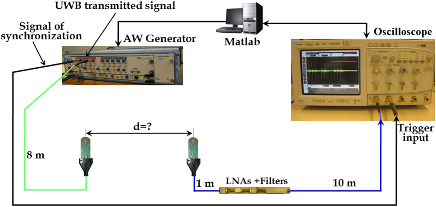
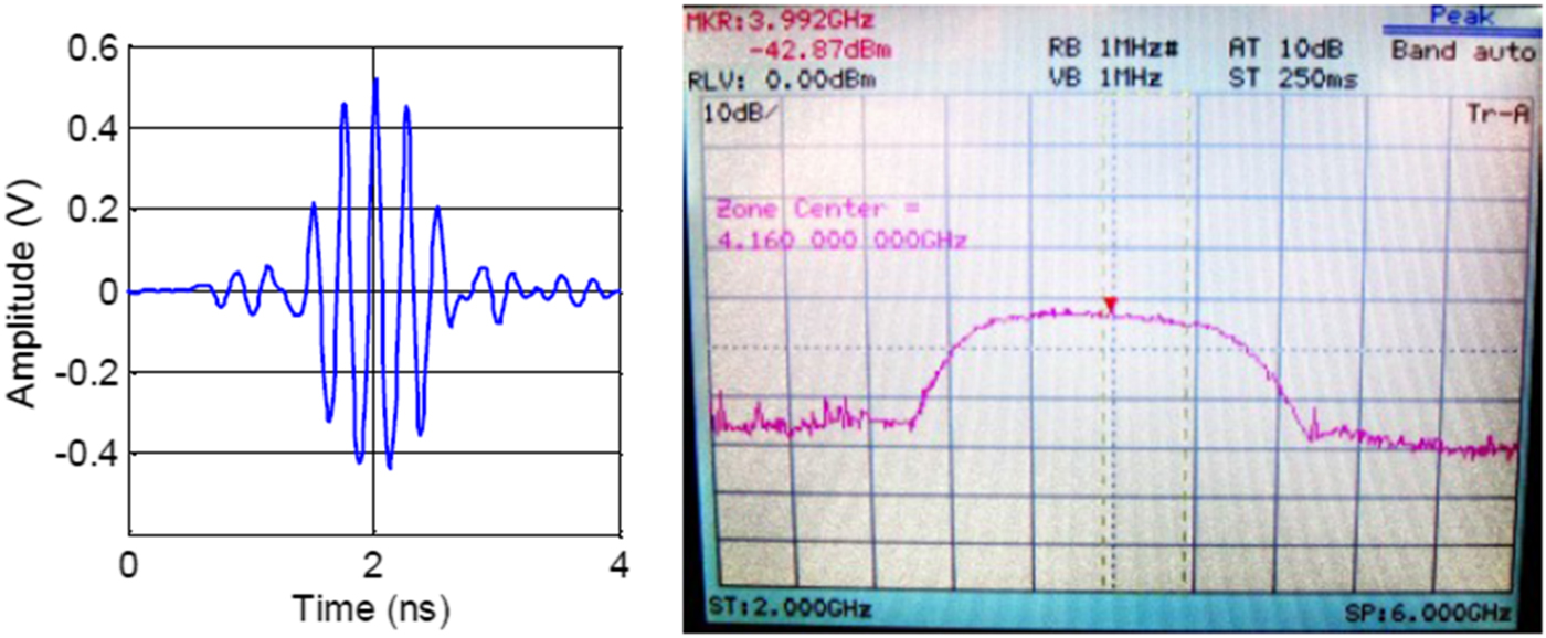
Figure 4 shows the measurement test bed setup that has been used in a laboratory environment to analyze the ranging accuracy of the proposed ED receiver architecture. The central controller of the ranging system is a PC running Matlab. The PC is connected to a Keysight M8190A Arbitrary Waveform Generator (AWG) via PCIe and to a Keysight wide-bandwidth digital oscilloscope DSO81004B via Ethernet. The parameters of the transmitted signal x(t) given by (1) are as follows:T c = 2 ns, L = 16, N c = 31, N sync = 16, C i = +0000 + −0 + 0 + 00 + 000 + 0 + + − − − 0 − +00 − + and f c = 3.993 GHz. The transmitted signal is generated by the AWG through the amplified analog output, which is connected to the Time Domain PulsOn P210 antenna [10] via an 8 m long coaxial cable. The transmitted waveform g(t) and its spectrum, measured at antenna's input are given in Fig. 5. The received signal captured by a second PulsOn P210 antenna, is amplified by a LNA (30 dB gain) and band-pass filtered ([3.33−4.66] GHz). before being sent towards the oscilloscope input channel 1 via a coaxial cable of 10 m.
Experimental setup to evaluate the proposed ED receiver.
Transmitted waveform and its spectrum.
The time synchronization between the transmitter and the receiver is realized by the connection of the Sample Marker output of the AWG to the oscilloscope input channel 2 programmed as the Trigger input. The received signals are acquired at a f e = 20 GHz sampling rate, then, they are stored on PC for offline signal processing. All signal processing operations, i.e., signal squaring, integration, PDP estimation and TOA estimation are performed using Matlab. In TOA estimation, a total delay of 85.43 ns introduced by the oscilloscope, cables and electronic components is removed.
To evaluate the performances of the proposed ED receiver for ranging estimation, we proceed as follows: The transmitter and receiver antennas are fixed on a wooden support for mobility, at 1.5 m height. They were placed at different distances in a laboratory environment from 3 to 17 m. The tests have been done for a total of 260 different distances separating the two antennas, which gives 260 TOA values to estimate. The proposed approach is evaluated over the average of 260 realizations using the root-mean-square error (RMSE) criterion given by
 $$RMSE = \sqrt {\displaystyle{1 \over {260}}\mathop \sum \limits_{i = 1}^{260} \vert e_i \vert ^2}, $$
where  $\vert e_i\vert = \vert d_i - c\hat \tau _{toa,i}\vert$ is the absolute error (AE), $\hat \tau _{toa,i}$ is the estimated TOA corresponding to the distance d i and c = 3 × 10⁸ m/s is the propagation velocity of the signals. The experiment is made in LOS and NLOS cases. The remainder of the parameters is given as follows: We set T b = 1 ns for the calculation of the energy blocks z(n) and z ov(n), and for TOA estimation with a CA-CFAR algorithm, we set N b = 32 and the guard cells duration is equal to 20 ns.
A) LOS case
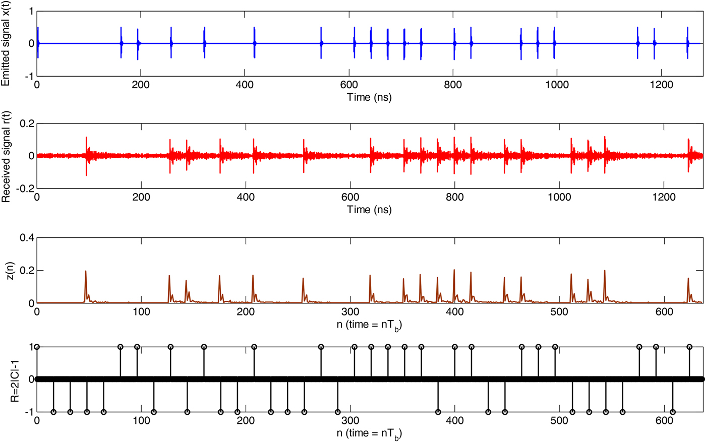
In LOS multipath environment case, there are no obstacles between the receiving antenna and the transmitter antenna. One preamble symbol of the emitted signal x(t), the received signal r(t), the energy blocks z(n) and the reference preamble sequence R are shown in Fig. 6.
Experimental measuring signals.
In order to find the optimal threshold multiplier T of the CA-CFAR algorithm for both architectures, we calculate the RMSE corresponding to each value of T on a given interval. The experimental results are presented in Fig. 7. We observe that the minimal values of the RMSE are almost constant starting from T = 0.18 for proposed ED receiver and starting from T = 0.28 for conventional ED receiver. This figure also shows that the ranging error of the proposed ED receiver (RMSE = 5.26 cm) is lower than that obtained by the conventional architecture (RMSE = 10.59 cm).
RMSE versus threshold multiplier T for both architectures (LOS case).

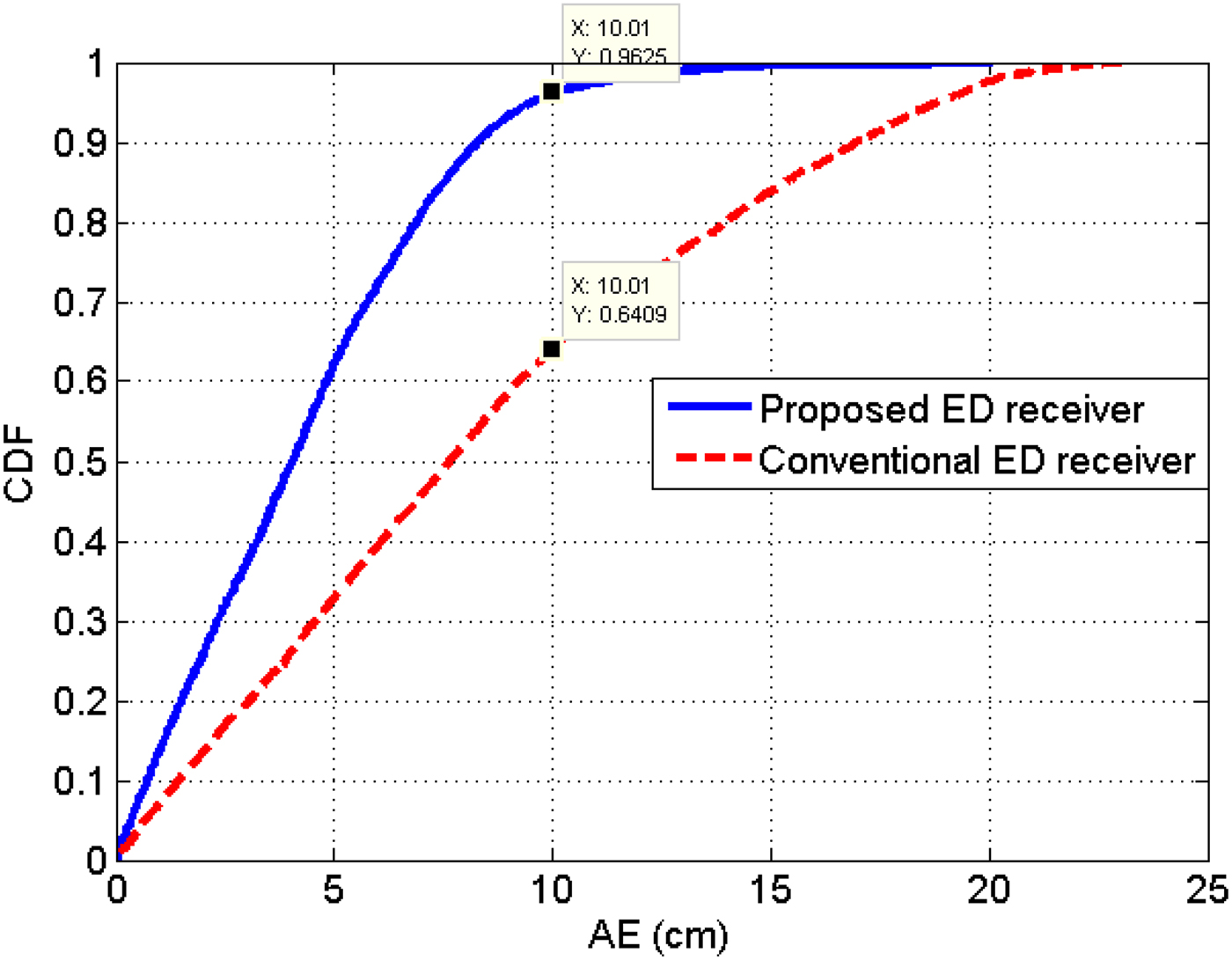
The cumulative distribution function (CDF) of the AE given by Fig. 8 shows that the proposed architecture provides better performance than the conventional architecture. It shows that  $96.25\% $ of the AE is less than 10 cm for the proposed ED receiver instead of $64.09\% $ for the conventional architecture.
The CDF of the AE for conventional and proposed ED receivers.
B) NLOS case
In the preceding case, the transmitter antenna and the receiving antenna have an LOS condition. Now, a metallic obstacle is placed between them in order to create an NLOS channel as indicated in Fig. 9. An example of a signal in such environment is given in Fig. 10.
Metallic obstacle between the transmitter antenna and the receiving antenna.

Comparison between LOS/NLOS received signals.
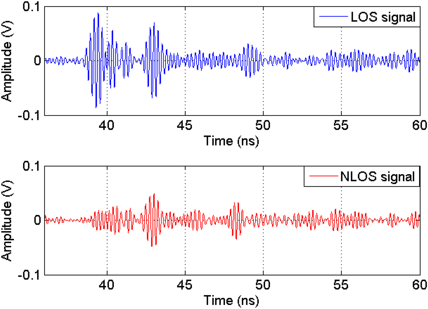
We show in Fig. 10 that the received signal in NLOS case is attenuated and delayed compared to that received in LOS case. In NLOS case, the direct path does not exist because the electromagnetic waves cannot pass through the metallic obstacles and we only see the reflected and diffracted signals. Consequently, an additional error affects the TOA estimation.
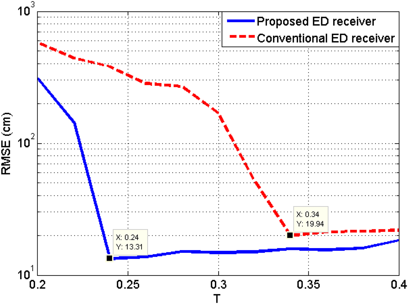
As in the case with LOS environment, we search the optimal threshold multiplier T of the CA-CFAR algorithm for both architectures by calculating the RMSE corresponding to each value of T on a given interval. The experimental results are presented in Fig. 11. We observe that the performance has been degraded for both architectures due to unavailability of the direct path and to the overlapping pulses in NLOS channel. This figure also shows that the ranging error of the proposed ED receiver (RMSE = 13.31 cm) is lower than that obtained by the conventional architecture (RMSE = 19.94 cm).
RMSE versus threshold multiplier T for both architectures (NLOS case).
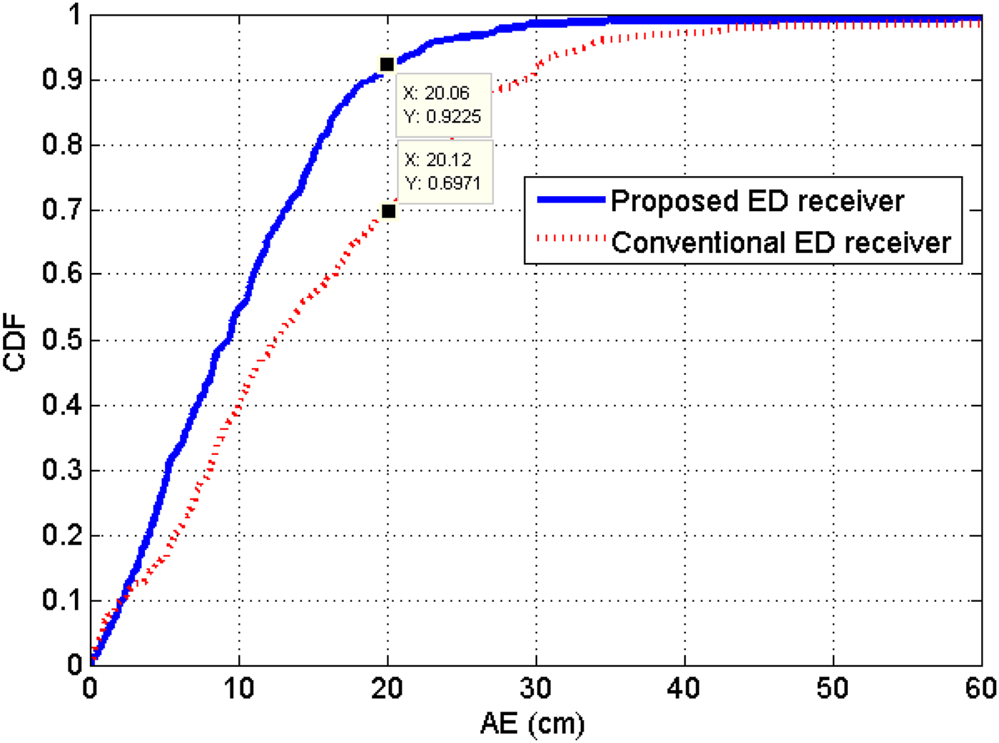
The CDF of the AE in NLOS case is given in Fig. 12. This figure shows that the proposed architecture provides better performance than the conventional architecture, and that 92.25% of the AE is less than 20 cm for the proposed ED receiver instead of 69.71% for the conventional architecture.
The CDF of the AE in NLOS case.
VI. CONCLUSION
We have proposed a new ED receiver architecture for ranging suitable for IEEE 802.15.4a standard. This architecture is based on two overlapping integrators, a sliding correlator, a CA-CFAR algorithm, and a block of interpolation. This architecture is very simple and low cost. Experimental results have shown that the proposed architecture offers better performances than the conventional architecture in both LOS and NLOS environments. As future work, the improvement of the interpolation method in NLOS environment with overlapping pulses can be carried out using a priori information of PDP.
ACKNOWLEDGEMENT
The authors would like to thank the anonymous reviewers for their help in improving the paper.
 Abdelmadjid Maali received his PhD degrees in Electrical Engineering in 2011 from the École Militaire Polytechnique, Algiers, Algeria. His thesis entitled “Localization via UWB Signals.” From November 2015 to July 2017, he was chair of the Microwaves and Radar Laboratory. He is now chair of the teaching and research unit on signal and communications. His research and teaching activities include digital signal processing and wireless communications.
 Geneviève Baudoin received the Dipl.-Ing. degree in 1977 from the École Nationale Supérieure des Télécommunications de Paris (now Telecom ParisTech), and the HDR Habilitation for PHD direction from Université Marne La Vallée en 2000. She was a lecturer at the University Paris-Ouest from 1977 to 1979; then she joined the Philips Research laboratory in France, as a research-engineer in the field of signal processing for medical applications of ultrasounds. She is Professor since 2001. She has been in charge of several pedagogical engineering programs in telecommunications and signal processing. For 10 years, she was chair of the telecommunications department. Then from February 2000 to August 2012, she was Research Director of ESIEE Paris. She is now chair of the System Engineering department. Her research and teaching activities include wireless communications, digital signal processing, and speech processing.
 Ammar Mesloub received the Ingenieur and the Master degree in Telecommunications from the École Militaire Polytechnique, Algiers, Algeria, in 2006 and 2009, respectively. He prepared his doctorate thesis in signal processing about combining time-frequency techniques with Blind Sources Separation algorithms to micro-Doppler signals. His research interests are in statistical signal processing, time-frequency analysis, and array signal processing with applications to radar and communications.


