


1. Introduction
Micro-air vehicles (MAVs) are becoming increasingly important in society, being demanded for security services, protection, surveillance, etc. Among the different configurations being explored for those vehicles, the greatest potential in terms of manoeuvrability and versatility is perhaps offered by bio-inspired configurations with flapping wings, similar to insects or small birds (Shyy et al. Reference Shyy, Aono, Kang and Liu2013; Haider et al. Reference Haider, Shahzad, Mumtaz Qadri and Ali Shah2021). These configurations are also the most complex from a technical point of view, involving unsteady aerodynamic mechanisms (i.e. leading edge vortex (LEV), rotational lift, wake capture and clap-and-fling) that have been described in the literature (Dickinson, Lehmann & Sane Reference Dickinson, Lehmann and Sane1999; Ellington Reference Ellington1999; Sane Reference Sane2003; Wang Reference Wang2005; Platzer et al. Reference Platzer, Jones, Young and Lai2008). However, one aspect that is not yet properly understood is the effect of wing flexibility, despite significant progress in recent years. The current understanding is that the aerodynamic performance can be enhanced, provided that the wing kinematics and the structural properties are selected adequately. Indeed, it has been shown that there exists an optimal range of flexibility for propulsion (Shyy et al. Reference Shyy, Aono, Chimakurthi, Trizila, Kang, Cesnik and Liu2010), and that wing flexibility can reduce the energetic cost of flight for natural flyers (Reid et al. Reference Reid, Schwab, Maxcer, Peterson, Johnson and Jankauski2019). Other effects have also been studied, like the influence of flexibility on the development and evolution of coherent structures surrounding the wings (Gordnier et al. Reference Gordnier, Chimakurthi, Cesnik and Attar2013). However, the accumulated knowledge is not yet sufficient to significantly influence current MAV designs. In fact, Haider et al. (Reference Haider, Shahzad, Mumtaz Qadri and Ali Shah2021) recently emphasized that the development of MAVs with flexible flapping wings has not yet reached capabilities similar to those of natural flyers.
The main problem that hinders further progress is the complexity of the interactions between flexible, flapping wings and the surrounding fluid. There are some studies that have tackled this problem, considering isotropic homogeneous wings (Hamamoto et al. Reference Hamamoto, Ohta, Hara and Hisada2007; Nakata & Liu Reference Nakata and Liu2012; Shahzad et al. Reference Shahzad, Tian, Young and Lai2018). Other authors have tried to make progress by simplifying the problem, considering chordwise or spanwise flexibility in a separate way. In fact, most of the available studies consider chordwise flexibility only, such as Alben (Reference Alben2012), Moored et al. (Reference Moored, Dewey, Smits and Haj-Hariri2012), Quinn, Lauder & Smits (Reference Quinn, Lauder and Smits2014), Olivier & Dumas (Reference Olivier and Dumas2016), Yeh & Alexeev (Reference Yeh and Alexeev2016), Hoover et al. (Reference Hoover, Cortez, Tytell and Fauci2018), Arora et al. (Reference Arora, Kang, Shyy and Gupta2018) and Liu, Liu & Huang (Reference Liu, Liu and Huang2022). The literature is vast, and additional references can be found in recent reviews (Quinn & Lauder Reference Quinn and Lauder2022; Wang, Tang & Zhang Reference Wang, Tang and Zhang2022). The two key questions addressed in the literature of chordwise-flexible wings/aerofoils are whether there is a flexibility (or a range of flexibilities) that leads to optimal propulsive performance, and what are the mechanisms that explain that optimal performance. While there is broad agreement on an affirmative answer for the first question, the literature proposes two non-exclusive mechanisms contributing to the answer to the second question. The first mechanism is a fluid–structure resonance, which results in maximum deflections of the trailing edge of the chordwise-flexible wing (Michelin & Llewellyn Smith Reference Michelin and Llewellyn Smith2009; Paraz, Schouveiler & Eloy Reference Paraz, Schouveiler and Eloy2016; Floryan & Rowley Reference Floryan and Rowley2018). The second mechanism is related to the phase lag between actuation and deformation. When properly tuned, it can lead to an optimal bending of the wing that projects the aerodynamic loads on the wing into the forward direction, hence maximizing thrust (Ramananarivo, Godoy-Diana & Thiria Reference Ramananarivo, Godoy-Diana and Thiria2011; Zhu, He & Zhang Reference Zhu, He and Zhang2014). In this regard, it is important to recall that in damped harmonic oscillators, both structural and damping nonlinearities affect the phase lag between forcing and response at all frequencies (Nayfeh & Mook Reference Nayfeh and Mook2008), resulting in phase lags at resonance different from the  $90^\circ$ phase lag obtained in linear oscillators. Indeed, Ramananarivo et al. (Reference Ramananarivo, Godoy-Diana and Thiria2011) attributed the enhanced propulsive performance of chordwise-flexible wings to nonlinear damping effects.
Obviously, the two mechanisms are not exclusive, and the optimal bending of a particular wing/kinematic might occur at the resonant frequency. An example reconciling these two mechanisms is by Goza, Floryan & Rowley (Reference Goza, Floryan and Rowley2020), who observed resonant behaviour leading to optimal performance in numerical simulations of chordwise-flexible two-dimensional aerofoils over a wide range of flexibilities. For large amplitudes of excitation, they reported that both resonance and nonlinear effects played a role. In particular, they observed that the peak in the structural response weakened and broadened in frequency, a behaviour that they attributed to added mass and nonlinear effects, such as flow separation and nonlinear vortex interaction. They also noted that this broader and weaker frequency response for large-amplitude oscillations is consistent with the nonlinear damping effects of a nonlinear oscillator, linking in this form their results to those of Ramananarivo et al. (Reference Ramananarivo, Godoy-Diana and Thiria2011).
Comparatively, there are fewer studies analysing the effect of spanwise flexibility, which are reviewed briefly below. One of the first studies available in the literature was performed using a panel method by Liu & Bose (Reference Liu and Bose1997). They showed that the propulsive efficiency of the planforms can be optimized by controlling the tip-to-root relative motion. In a similar fashion, also using a potential flow model, Zhu (Reference Zhu2007) reported simulations studying the effect of spanwise flexibility on fluid-driven wings with low effective inertia ( $\varPi _0 \approx {O}(10^{-4})$) and inertia-driven wings with a typical effective inertia of insects ( $\varPi _0 \approx {O}(10^{-1})$). While fluid-driven flexible wings exhibited no enhancement in performance with respect to rigid wings whichever the flexibility, thrust was greatly increased for inertia-driven wings when increasing the flexibility up to an optimal value. A corresponding increase in propulsive efficiency was not observed. This was followed by an influential experiment reported by Heathcote, Wang & Gursul (Reference Heathcote, Wang and Gursul2008). These authors studied spanwise-flexible wings in heaving motion immersed on a free stream in the range $Re=10\,000\unicode{x2013}30\,000$, based on the incoming velocity. They found an increase in thrust for a limited degree of flexibility, with little influence of the Reynolds number in the range considered. The experiment of Heathcote et al. (Reference Heathcote, Wang and Gursul2008) has been the subject of several numerical simulations with various methods. For example, Chimakurthi et al. (Reference Chimakurthi, Tang, Palacios, Cesnik and Shyy2009), Aono et al. (Reference Aono, Chimakurthi, Cesnik, Liu and Shyy2009) and Kang et al. (Reference Kang, Aono, Cesnik and Shyy2011) employed Reynolds-averaged Navier–Stokes simulations with a nonlinear beam structural model, while Gordnier et al. (Reference Gordnier, Chimakurthi, Cesnik and Attar2013) used a high-order implicit large eddy simulation to model the flow. These numerical studies have shown a non-monotonic response of the mean thrust with respect to the wing flexibility, and a sudden loss of performance for very flexible wings. Shyy et al. (Reference Shyy, Aono, Chimakurthi, Trizila, Kang, Cesnik and Liu2010) suggest that the poor aerodynamic performance of the very flexible wings is related to the cumulative effect of the effective angle of attack and to the role of the tip-to-root relative motion, with large phase lags for the very flexible wings. Gordnier et al. (Reference Gordnier, Chimakurthi, Cesnik and Attar2013) reported a detailed analysis of the phenomena that drive the fluid–structure interaction, for a configuration corresponding to the Heathcote et al. (Reference Heathcote, Wang and Gursul2008) experiments. They showed that for the moderately flexible wings, higher effective angles of attack result in the development of a stronger LEV. Due to the more rapid effective bend up and down motion towards the tip of the wing, the convection of the LEV is inhibited, leading to a superior aerodynamics performance. This further supports the idea that the phase lag between tip and root motions is a key parameter in the fluid–structure interaction of spanwise-flexible wings.
To the best of our knowledge, Kodali et al. (Reference Kodali, Medina, Kang and Aono2017) is the first work that explicitly linked the enhancement in aerodynamic performance with a resonance phenomenon when spanwise flexibility is considered. However, this fluid–structure resonance can also be inferred from previous works, such as Zhu (Reference Zhu2007) and Qi et al. (Reference Qi, Liu, Shyy and Aono2010). Kodali et al. (Reference Kodali, Medina, Kang and Aono2017) reported a two-way coupled aeroelastic model of a heaving, spanwise-flexible wing in forward flight. The aerodynamics was modelled using two-dimensional, unsteady potential flow, evaluated at each spanwise location, so that this represents a high Reynolds number approximation. The structure was modelled using an Euler–Bernoulli beam equation. The analysis was performed by changing the wing aspect ratio while keeping constant the remaining structural parameters, thus varying the natural frequency of the wing. They found the optimal aerodynamic performance (defined in terms of energy requirements, not thrust production) when the natural frequency matched the oscillation frequency, i.e. a resonance was observed as already mentioned. They also found that the relative motion between the tip and root sections lagged by roughly  $90^\circ$ for the optimal flexibility. A final observation was that the structural response was governed by the first natural mode of the structure, with the remaining modes being barely excited.
Note, however, that the use of linear models for aerodynamics (i.e. potential aerodynamics) and structure (i.e. Euler–Bernoulli beam equations) somewhat limits the scope of the work of Kodali et al. (Reference Kodali, Medina, Kang and Aono2017), especially taking into account the aforementioned role of nonlinearities in the aerodynamic performance of chordwise-flexible aerofoils/wings. These limitations are not present in other studies. For instance, Zhu (Reference Zhu2007) uses a potential aerodynamic model in combination with a nonlinear structural model, and Qi et al. (Reference Qi, Liu, Shyy and Aono2010) use a lattice Boltzmann flexible particle method (i.e. nonlinear aerodynamic and structural models) at very low Reynolds numbers ( $Re={O}(10^2)$). Interestingly, while these three studies found optimal values for flexibility in the inertia-driven range ( $\varPi _0 \approx {O}(10^{-1})$), consistent with a fluid–structural resonance, they show important differences in terms of mean thrust coefficients, propulsive efficiencies, and phase lag between excitation and structural response (i.e. wing tip displacement). The reasons for these discrepancies are not completely clear, given the differences in the wing kinematics, flight conditions (forward flight versus hover flight), Reynolds number, structural nonlinearities and fluid damping (linear versus nonlinear, leading edge vortex effects, viscous versus inviscid).
In view of the above, we aim to characterize the role of fluid–structure resonance in the enhancement of aerodynamic performance of spanwise-flexible wings. In particular, we perform direct numerical simulations of the incompressible flow around heaving and pitching flexible wings in forward flight at  $Re=1000$. We consider rectangular wings with two different aspect ratios, and several values of the effective stiffness. This will allow us to explore if the aspect ratio is important only as a structural parameter (i.e. changing the natural frequency of the structure, as in the study of Kodali et al. Reference Kodali, Medina, Kang and Aono2017), or if it is also relevant in terms of the generation of aerodynamic loads. Our study analyses a Reynolds number that is intermediate to those available in the literature, which are either much lower (Qi et al. Reference Qi, Liu, Shyy and Aono2010) or much higher (Liu & Bose Reference Liu and Bose1997; Heathcote et al. Reference Heathcote, Wang and Gursul2008; Aono et al. Reference Aono, Chimakurthi, Cesnik, Liu and Shyy2009; Chimakurthi et al. Reference Chimakurthi, Tang, Palacios, Cesnik and Shyy2009; Kang et al. Reference Kang, Aono, Cesnik and Shyy2011; Gordnier et al. Reference Gordnier, Chimakurthi, Cesnik and Attar2013). Contrary to previous works, direct numerical simulations of the flow allow us to represent in detail the surrounding fluid, allowing a proper description of the nonlinear and viscous character of the fluid damping at intermediate Reynolds numbers. The paper is structured as follows. Section 2 presents the problem definition, followed by the numerical details of the algorithms used to solve the fluid–structure interaction problem. Section 3 shows the results of the simulations, characterizing the aerodynamic forces, the structural response of the wing, and the mechanisms that explain the changes in the aerodynamic forces with the wing's flexibility. Finally, conclusions are presented in § 4.
2. Methodology
2.1. Problem definition
A finite wing in forward flight immersed in a uniform and steady free stream of magnitude  $U_\infty$ is considered. The fluid has constant density and viscosity ( $\rho _f$ and $\mu$), resulting in a Reynolds number based on the chord of the wing, $c$, and the free-stream velocity, given by $Re = \rho _f U_\infty c / \mu = 1000$. The wing is a rectangular flat plate with finite aspect ratio ${A{\kern-4pt}R} =b/c$, where $b$ is the span of the wing, and the dimensionless thickness is $h_s^* = h_s/c = 0.02$. The wing is rigid in the chordwise direction, and flexible in the spanwise direction. To study the effect of the wing span, two aspect ratios are considered, ${A{\kern-4pt}R} = 2$ and 4.
A heaving and pitching motion is imposed on the mid-span section of the wing. The rest of the wing deforms passively. The kinematics is described by the laws
 $$\begin{gather} h(t) = h_0 \cos\left(\frac{2{\rm \pi} t}{T}\right), \end{gather}$$
 $$\begin{gather}\theta(t) = \theta_0 \cos\left(\frac{2{\rm \pi} t}{T} + \phi_{hp}\right), \end{gather}$$
where  $h_0$ is the heaving amplitude, $\theta _0$ is the pitching amplitude, $\phi _{hp}$ is the phase difference between heaving and pitching motions, and $T$ is the oscillation period. We also define the frequency of the imposed motion as $f=1/T$, the angular frequency as $\omega = 2{\rm \pi} f$, and the reduced frequency as $k = {\rm \pi}f c / U_\infty$. The Strouhal number based on the chord of the wing is defined as $St_c = f c/U_\infty$. The pivoting axis for pitching is placed at the mid-chord, $x/c=0.5$. The kinematic parameters shown in table 1 have been selected to ensure positive thrust and relatively strong LEVs, with flapping amplitude large enough to ensure non-negligible nonlinear effects. Incidentally, these parameters yield optimal propulsive efficiency for a system of two aerofoils arranged in horizontal tandem (for details, see Martínez-López Reference Martínez-López2019; Ortega-Casanova & Fernández-Feria Reference Ortega-Casanova and Fernández-Feria2019; Martínez-Muriel Reference Martínez-Muriel2023), which will be the subject of a follow-up study.
Parameters of the kinematics imposed at the mid-section of the wing.
The material properties of the wing are varied in order to study the effect of spanwise flexibility. As discussed in the next subsection, this is done by adjusting the first natural frequency of the wing in vacuum,
 \begin{equation} \frac{\omega_n c}{U_\infty} = \beta_n^2 \sqrt{\frac{E^* h_s^{*2}}{12\rho^*}}, \end{equation}
where  $\beta _n$ is the first eigenvalue of the transcendental equation
 \begin{equation} \cos(\beta_i {A{\kern-4pt}R}/2) \cosh(\beta_i {A{\kern-4pt}R}/2) + 1 = 0, \end{equation}
as described in Kodali et al. (Reference Kodali, Medina, Kang and Aono2017). In (2.2),  $E^* = E/{\rho _f U_\infty ^2}$ is the normalized Young's modulus, and $\rho ^* = \rho _s/\rho _f$ is the solid to fluid density ratio. Following Shyy et al. (Reference Shyy, Aono, Chimakurthi, Trizila, Kang, Cesnik and Liu2010), we define the effective inertia and effective stiffness of the wings, respectively, as
 \begin{equation} \varPi_0 = \rho^* h_s^* \left(\dfrac{k}{\rm \pi}\right)^2, \quad \varPi_1 = \dfrac{E^*h_s^{*3}}{12}. \end{equation}
These two parameters,  $\varPi _0$ and $\varPi _1$, serve to characterize the structural and inertia properties of the wing.
In the present study,  $\varPi _0$ is kept constant while $\varPi _1$ is varied to cover a wide range of frequency ratios, $\omega _n/\omega$, as shown in table 2.
Overview of problem parameters and simulation results:  ${A{\kern-4pt}R}$ is the aspect ratio, $\omega _n/\omega$ and $\omega _{n,f}/\omega$ are the ratios of natural frequency in vacuum and in fluid, respectively, to the angular frequency of the flapping motion, $\varPi _1$ is the effective stiffness, $c/\Delta r$ is the grid resolution used in the refined zone of the domain, and $\overline {C_T}$, ${C_L}^{rms}$ and $\eta _p$ are the time-averaged thrust coefficient, the root-mean-square (r.m.s.) of the lift coefficient, and the propulsive efficiency, respectively.

A density ratio  $\rho ^* = 20$ is selected such that $\rho ^* h_s^* = 0.4$ and a value $\varPi _0 = 0.0984$ are obtained. This value is of the same order of magnitude of the effective inertia of insects (Hamamoto et al. Reference Hamamoto, Ohta, Hara and Hisada2007; Jongerius & Lentink Reference Jongerius and Lentink2010; Ren et al. Reference Ren, Wang, Li and Chen2013; Shyy et al. Reference Shyy, Aono, Kang and Liu2013) and birds (Kodali et al. Reference Kodali, Medina, Kang and Aono2017). The range of the effective stiffness considered here, $\varPi _1 \sim {O}(10^{-1})\unicode{x2013}{O}(10^{2})$, is comparable to that considered in previous studies (Fu et al. Reference Fu, Liu, Shyy and Qiu2018). In addition, a rigid wing ( $\varPi _1 \rightarrow \infty$) is also included in the study to provide a baseline for comparison.
2.2. Structural model
A lumped-torsional flexibility model is used to simulate the spanwise flexibility of the wing. The wing is discretized into  $N_B = 5{A{\kern-4pt}R} + 1$ rigid segments connected by torsional springs, as depicted in figure 1(a). To avoid overlapping when the segments rotate relative to each other, the segments are separated a distance $e=h_s$ when placed horizontally. Note that a similar approach was employed by Arranz, Flores & Garcia-Villalba (Reference Arranz, Flores and Garcia-Villalba2022a) to simulate the chordwise flexibility of self-propelling plates.
(a) Sketch of the multi-body model to describe qualitatively the spanwise flexibility of a wing, where the system of bodies is connected via torsional springs. (b) Sketch of the degrees of freedom ( $\phi _i$) between two consecutive segments.

Under this model, the wing can be considered as a multi-body system of  $N_B$ bodies with $1+N_B$ degrees of freedom; namely, the vertical displacement ( $h$), the pitching angle ( $\theta$) and the relative rotation angles between each segment, $\phi _i$, $i = 1,\ldots,N_B-1$ (see figure 1b).
For the sake of brevity, only a summary of the most representative aspects of the method is presented here; further details can be found in Arranz et al. (Reference Arranz, Martínez-Muriel, Flores and García-Villalba2022b). The governing equations for the multi-body system can be cast in the form
 \begin{equation} \boldsymbol{\mathsf{H}}(\boldsymbol{q})\,\ddot{\boldsymbol{q}} + \boldsymbol{\mathsf{C}}(\boldsymbol{q}, \dot{\boldsymbol{q}}) = \boldsymbol{\xi} + \boldsymbol{\xi}_h, \end{equation}
where  $\boldsymbol {q} = [h,\theta,\phi _1,\ldots,\phi _{N_B-1}]$ is the vector of generalized coordinates, $\boldsymbol{\mathsf{H}}$ is the generalized inertia matrix, $\boldsymbol{\mathsf{C}}$ is the generalized bias force vector – which includes Coriolis and centrifugal accelerations $\boldsymbol {\xi } = [0,0,-K\phi _1,\ldots,-K\phi _{N_B-1}]$, where $K$ is the torsional spring constant – and $\boldsymbol {\xi }_h$ is the vector of hydrodynamic forces acting on the wing. In order to compute the generalized inertia matrix $\boldsymbol{\mathsf{H}}$ and the generalized bias force $\boldsymbol{\mathsf{C}}$, the open-source Rigid Body Dynamics Library developed by Felis (Reference Felis2017) is used. The $\boldsymbol{\mathsf{H}}$ matrix is computed through the composite rigid-body algorithm, and the $\boldsymbol{\mathsf{C}}$ vector is computed through the recursive Newton–Euler algorithm. The stiffness of the torsional springs $K$ is adjusted by solving an eigenvalue problem as done by Arora et al. (Reference Arora, Kang, Shyy and Gupta2018), so that the first natural frequency of the multi-body system matches the first natural frequency of the corresponding flexible structure in vacuum, $\omega _n$.
2.3. Flow solver
The fluid solver employed in this work is TUCAN, a constant-density fluid solver that uses the immersed boundary method (IBM) proposed by Uhlmann (Reference Uhlmann2005) to model the presence of the wing in the flow. The three-dimensional Navier–Stokes equations for an incompressible flow modified for the IBM are used to describe the fluid dynamics:
 $$\begin{gather} \boldsymbol{\nabla} \boldsymbol{\cdot} \boldsymbol{u} = 0, \end{gather}$$
 $$\begin{gather}\dfrac{\partial \boldsymbol{u}}{\partial t} + (\boldsymbol{u} \boldsymbol{\cdot} \boldsymbol{\nabla}) \boldsymbol{u} ={-}\boldsymbol{\nabla} p + \nu\,\nabla^2 \boldsymbol{u} + \boldsymbol{f}_{\textit{IBM}}, \end{gather}$$
 $$\begin{gather}\boldsymbol{u}(\boldsymbol{x}) = \boldsymbol{U}_{\partial\varGamma} \quad \forall \boldsymbol{x} \in \partial\varGamma, \end{gather}$$
where  $\boldsymbol {u}$ is the velocity field, $p$ is the kinematic pressure (i.e. pressure over the fluid density $\rho _f$), $\nu = \mu /\rho _f$ is the kinematic viscosity, and $\boldsymbol {f}_{\textit {IBM}}$ is the IBM forcing term that models the presence of the wing. This forcing term ensures that the no-slip boundary condition (2.6c) is satisfied at the solid boundaries (i.e. on the surface of the wing segments), where $\boldsymbol {U}_{\partial \varGamma }$ is the velocity at the segments’ surface. To compute the velocity at the wing surface, (2.5) is solved together with (2.6). In particular, at every time step, the hydrodynamic forces are computed and used to update the position and velocity of the segments according to (2.5). Then the new hydrodynamic forces are computed from (2.6), leading to a weak coupling between both systems of equations. This might result in a small incompatibility between the flow field at the wing surface and the wing's velocity at the end of the time step, which in any case remains bounded and negligible over the simulation time. The weak coupling between the equations is also known to lead to stability problems for density ratios below 1.2 (Uhlmann Reference Uhlmann2005). However, in the range of parameters considered in this study, no stability issues have been observed (Arranz et al. Reference Arranz, Martínez-Muriel, Flores and García-Villalba2022b). Two different meshes are required. First, a staggered Cartesian grid is used to discretize the fluid variables, referred to as the Eulerian mesh. The spatial derivatives appearing in (2.6) are approximated by centred finite differences in the staggered grid defined by the Eulerian mesh. Second, the surface of the wing's segments ( $\partial \varGamma$) is discretized with a Lagrangian mesh that follows the active/passive motion of the solid body within the fluid. The boundary condition on the wing surface (i.e. (2.6c)) is imposed on this Lagrangian mesh, which requires the use of discrete delta functions to interpolate velocities and the IBM forcing term back and forth between the Lagrangian and Eulerian meshes. A complete description of the fluid solver implemented in TUCAN can be found in Moriche (Reference Moriche2017).
TUCAN has already been employed successfully, for both two-dimensional (Moriche, Flores & Garcia-Villalba Reference Moriche, Flores and Garcia-Villalba2017; Martínez-Muriel & Flores Reference Martínez-Muriel and Flores2020) and three-dimensional (Moriche, Flores & García-Villalba Reference Moriche, Flores and García-Villalba2016; Arranz et al. Reference Arranz, Moriche, Uhlmann, Flores and García-Villalba2018; Arranz, Flores & Garcia-Villalba Reference Arranz, Flores and Garcia-Villalba2020; Moriche et al. Reference Moriche, Sedky, Jones, Flores and García-Villalba2021) aerodynamics problems, and also for cardiac flows (García-Villalba et al. Reference García-Villalba2021; Gonzalo et al. Reference Gonzalo2022).
2.4. Computational set-up
Direct numerical simulations of the problem described in § 2.1 are performed using TUCAN. The time step is selected such that the Courant–Friedrichs–Lewy (CFL) number is lower than 0.3. The simulations are performed in a computational domain with dimensions  $14c \times 11c \times 7c$ in the streamwise, spanwise and vertical directions, respectively. A refined zone is defined roughly at the middle of the domain with a uniform grid spacing in all directions, $\Delta r$. Outside this refined region, a constant stretching of 1 % is applied to the grid in all directions. The wings are located in the refined zone, which has size $(2c \times L_{y,r} \times 3c)$, where $L_{y,r}=({A{\kern-4pt}R} +1)c$ depends on the aspect ratio of the wing, leaving enough space for the boundaries not to have spurious effects on this refined zone, and enough space downstream to develop the wake properly.
The origin of the reference system is located at the leading edge of the mid-span section of the wing. The free-stream condition is modelled with an inflow velocity at the inlet boundary ( $x/c=-4.75$), while the outflow has been modelled with an advective boundary condition ( $\partial \boldsymbol {u}/\partial t + U_\infty \,\partial \boldsymbol {u}/\partial x = 0$) at the outlet ( $x/c=9.25$). Free-slip boundary conditions are imposed in the lateral boundaries.
The simulations are started in a grid that uses a lower resolution,  $\Delta r = c/56$, in the refined zone, which captures qualitatively the dynamics of the problem as shown in Appendix B. These simulations are run for four cycles. Then, for selected configurations (see table 2), two additional cycles are run at a higher resolution, $\Delta r = c/96$. This higher resolution is chosen based on the grid refinement study performed by Arranz et al. (Reference Arranz, Flores and Garcia-Villalba2020) for a similar problem at the same Reynolds number. We have checked that the numbers of cycles run in all simulations are enough to ensure that aerodynamic forces and the flow in the vicinity of the wing are periodic. The rigid segments that represent the Lagrangian mesh are discretized using $\Delta _{l} = c/96$ irrespective of the resolution used for the Eulerian grid.
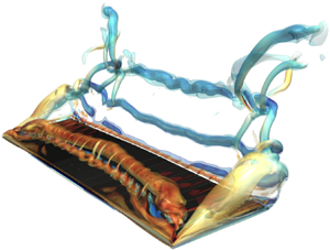
Finally, note that the space between the segments,  $e$, is larger than the Eulerian grid spacing, allowing fluid to pass through these gaps. The effect of the gaps is negligible to the global evolution of forces, as shown in Appendix A, although they leave a visible footprint in the flow structures, as will be shown below.
3. Results
3.1. Force coefficients
First, thrust and lift coefficients,  $C_T$ and $C_L$, respectively, for cases with ${A{\kern-4pt}R} =4$, are presented as functions of time in figure 2. These coefficients are defined as
 \begin{equation} C_T = \frac{-2\boldsymbol{F}\boldsymbol{\cdot} \boldsymbol{e}_x}{\rho_f U_\infty^2 S}, \quad C_L = \frac{2\boldsymbol{F}\boldsymbol{\cdot} \boldsymbol{e}_z}{\rho_f U_\infty^2 S}, \end{equation}
where  $\boldsymbol {F}$ is the total aerodynamic force and $\boldsymbol {e}_k$ is the unitary vector in the $k$-axis direction. Due to the symmetry of upstroke and downstroke motions, the time-averaged value of the thrust coefficient is different from 0 in general, while the mean value of the lift coefficient is 0. As expected, there is a clear influence of the wing flexibility on the evolution of the forces. When moving from rigid to more flexible wings (i.e. decreasing $\varPi _1$), a non-monotonic behaviour of the maximum values of both $C_T$ and $C_L$ is observed, in accordance with previous studies of heaving wings in forward flight (Heathcote et al. Reference Heathcote, Wang and Gursul2008) and hovering wings (Qi et al. Reference Qi, Liu, Shyy and Aono2010). Focusing on $C_T$, figure 2(a) shows that its maximum value during the downstroke increases with the flexibility for cases 1, 2 and 3. Increasing flexibility beyond case 3 results in a sudden drop in $C_T$, as shown by cases 4 and 5. Moreover, the time instant at which the peak in both force coefficients is produced depends on the flexibility. For the rigid case, $C_T$ peaks at $t/T\approx 0.15$, prior to mid-downstroke. For case 3, the maximum occurs at $t/T\approx 0.3$, after the mid-downstroke. A similar behaviour can be observed in figure 2(b) for $C_L$ in terms of maximum values and times. The temporal evolutions of $C_T$ and $C_L$ for the cases with ${A{\kern-4pt}R} =2$, and their variation with the wing flexibility, are qualitatively similar to those shown in figure 2 for ${A{\kern-4pt}R} = 4$, and are provided as supplementary material available at https://doi.org/10.1017/jfm.2023.308.
Temporal evolution of (a) thrust coefficient  $C_T$, and (b) lift coefficient $C_L$, of ${A{\kern-4pt}R} =4$ wings. Line colours correspond as follows: blue solid line, 1 (rigid); magenta solid line, 2 (intermediate); red solid line, 3 (optimal); black solid line, 4 (sub-optimal); black dashed line, 5 (sub-optimal 2).

Given the temporal evolution of the forces, we choose to characterize the aerodynamic performance of the wings in terms of the mean thrust coefficient,  $\overline {C_T}$, and the root-mean-square (r.m.s.) of the lift coefficient, ${C_L}^{rms}$. Note that we choose ${C_L}^{rms}$ instead of $\overline {C_L}$, since the latter is zero for the wing kinematics considered here. Figure 3 shows the variation of $\overline {C_T}$ and ${C_L}^{rms}$ with the effective stiffness of the wing. The effect of the aspect ratio of the wing in $\overline {C_T}$ and ${C_L}^{rms}$ is captured by re-scaling the effective stiffness (horizontal axis on the top) with the factor $(2/{A{\kern-4pt}R} )^4$, as proposed by Kang et al. (Reference Kang, Aono, Cesnik and Shyy2011). Figure 3 suggests that this re-scaling is able to collapse into a single curve the force coefficients of the flexible cases with ${A{\kern-4pt}R} =4$ and 2, at least for values $\varPi _1(2/{A{\kern-4pt}R} )^4 \lesssim 10$.
(a) Mean thrust coefficient  $\overline {C_T}$, and (b) r.m.s. of lift coefficient $C^{rms}_L$. Blue symbols are for ${A{\kern-4pt}R} =2$; magenta symbols are for ${A{\kern-4pt}R} =4$.

Overall, figure 3 shows that the variabilities of  $\overline {C_T}$ and ${C_L}^{rms}$ with the wing's effective stiffness are qualitatively similar, presenting a monotonic increase from stiffer to more flexible cases (i.e. decreasing $\varPi _1$) until a peak is reached. Decreasing the effective stiffness beyond this point results in a sudden drop of $\overline {C_T}$ and ${C_L}^{rms}$, as anticipated already when discussing the temporal evolution of the coefficients. Figure 3(a) also allows us to analyse the effect of ${A{\kern-4pt}R}$ on the mean thrust coefficient. For the rigid wings, there is a factor 1.25 between the $\overline {C_T}$ values for ${A{\kern-4pt}R} =2$ and ${A{\kern-4pt}R} =4$. For the flexible wings, changing ${A{\kern-4pt}R}$ implies changing the re-scaled effective stiffness, i.e. moving along the top horizontal axis of figure 3(a). In particular, a change of ${A{\kern-4pt}R}$ from 2 to 4 results in a shift of more than a decade (a factor $1/16$). For the range of flexibilities near the peak, this yields a factor up to 2.25 in $\overline {C_T}$. This suggests that the effect of ${A{\kern-4pt}R}$ on the structural properties of flexible wings is dominant over its direct effect on the generation of aerodynamic forces.
In the following, we loosely denote as optimal cases for each aspect ratio those that correspond to the peak in the aerodynamic performance. We denote as sub-optimal cases those that are beyond the sudden drop in performance (i.e. for smaller  $\varPi _1$ than the optimal cases). We denote as intermediate cases those between the rigid and the optimal cases. For reference, this terminology is included in table 2. The stereotypical cases selected (somewhat arbitrarily) for analysis are cases with id $1, 2, 3, 4$ for ${A{\kern-4pt}R} =4$ and $6, 9, 11, 12$ for ${A{\kern-4pt}R} =2$, denoting them as rigid, intermediate, optimal and sub-optimal, respectively.
The aerodynamic force coefficients in figure 3 are also plotted as functions of the ratio of natural frequency in fluid over the frequency of the motion,  $\omega _{n,f}/\omega$ (see horizontal axis on the bottom).
The natural frequency in fluid is computed as in Moore (Reference Moore2015) and Arora et al. (Reference Arora, Kang, Shyy and Gupta2018),
 \begin{equation} \frac{\omega_{n,f}}{\omega} = \frac{\omega_{n}/\omega}{\sqrt{1+I_a}} = \frac{\beta_n^2}{2{\rm \pi}} \sqrt{ \frac{\varPi_1}{\varPi_0 (1+I_a)} } = \frac{a}{2{\rm \pi}} \sqrt{ \frac{\varPi_1 (2/{A{\kern-4pt}R})^4}{\varPi_0 (1+I_a)} }, \end{equation}
where the dimensionless parameter  $I_a$ represents the additional moment of inertia of the wing due to the added mass term (Arora et al. Reference Arora, Kang, Shyy and Gupta2018), and the solution to (2.3) has been expressed as $\beta _n^2 = a (2/{A{\kern-4pt}R} )^2$, with $a$ equal to a positive constant. Since in the present study $\varPi _0$ and $I_a$ are held constant for all cases, (3.2) yields a linear relationship between $\log _{10}(\omega _{n,f}/\omega )$ and $\log _{10}(\varPi _1 (2/{A{\kern-4pt}R} )^4)$, allowing the use of two horizontal axes in figure 3. Indeed, given the straightforward physical interpretation of $\omega _{n,f}/\omega$, in the following we will use this quantity to characterize the wing's flexibility, instead of $\varPi _1(2/{A{\kern-4pt}R} )^4$. Finally, the natural frequency in fluid given by (3.2) approximates well that obtained from a linear stability analysis of the coupled fluid–structure system (Goza et al. Reference Goza, Floryan and Rowley2020). For example, the value of $\omega _{n,f}$ using (3.2) for the cases with $\varPi _1 = 20$ in Goza et al. (Reference Goza, Floryan and Rowley2020) is $\omega _{n,f}\approx 6.1{\rm \pi} U_\infty /c$, while the one obtained from the linear stability analysis is $\omega _{n,f}\approx 6.2{\rm \pi} U_\infty /c$.
The results in figure 3 show that the optimal flexibility is found for values of  $\omega _{n,f}/\omega$ slightly above 1 (see also table 2 for the precise values). For $\omega _{n,f}/\omega <1$, the drop in performance is observed, for both wing aspect ratios. Similar observations can be inferred from the works of Zhu et al. (Reference Zhu, He and Zhang2014) and Qi et al. (Reference Qi, Liu, Shyy and Aono2010), although for different kinematics and Reynolds number. We also analyse the effect of flexibility on the power requirements and the propulsive efficiency of the wings. The propulsive efficiency of the wing is computed as
 \begin{equation} \eta_p = \frac{\overline{C_T}}{\bar{P}}, \end{equation}
where  $\bar {P}$ is the time-averaged non-dimensional input power of the wing. The instantaneous non-dimensional input power is computed similarly as in Arranz et al. (Reference Arranz, Flores and Garcia-Villalba2022a), by using the reaction forces and moments on the segment whose motion is imposed.
The reaction force on the vertical direction is denoted  $R_z$, and the reaction pitching moment is denoted $R_\theta$. Then the instantaneous non-dimensional power for the flexible wings is computed as
 \begin{equation} P(t) = \frac{2}{\rho_f U_\infty^3 S} \left( \max( R_z(t)\,\dot{h}(t),0 ) + \max( R_\theta(t)\, \dot{\theta}(t), 0 ) \right). \end{equation}
Note that the definition for the power is such that no extraction of energy from the fluid is considered (Berman & Wang Reference Berman and Wang2007; Vejdani et al. Reference Vejdani, Boerma, Swartz and Breuer2018; Jurado et al. Reference Jurado, Arranz, Flores and García-Villalba2022).
Figure 4(a) shows the temporal evolution of the required input power for the four stereotypical cases with  ${A{\kern-4pt}R} =4$. The peak power input for the intermediate and optimal cases with ${A{\kern-4pt}R} =4$ is roughly twice that for the rigid case. Thus, not surprisingly, producing more thrust requires more power to move the wing. When comparing the intermediate and rigid cases, the increase in power input for the intermediate case occurs only during the first half of each stroke. For the optimal case, whose thrust peak is delayed (see figure 2a), the increase in required power extends to 80 % of each half-cycle. Note that although the peak thrust of the optimal case is approximately 50 % higher than the peak thrust of the intermediate case (see figure 2a), the peak power inputs for these two cases are not that different. For the sub-optimal case, the power input drops significantly, reaching a level similar to that in the rigid case.
(a) Power requirements for  ${A{\kern-4pt}R} =4$ cases. Line colours correspond as follows: blue solid line, rigid; magenta solid line, intermediate; red solid line, optimal; black solid line, sub-optimal. (b) Propulsive efficiency $\eta _p$ for rigid, intermediate, optimal and sub-optimal cases for both aspect ratios.

Figure 4(b) shows the propulsive efficiency for all cases considered (including both aspect ratios), as a function of the frequency ratio. When comparing the optimal case with the rigid case, we observe a small increase in the efficiency (for  ${A{\kern-4pt}R} =4$ from ${\eta =0.217}$ to 0.248, and for ${A{\kern-4pt}R} =2$ from $\eta =0.177$ to 0.237). The propulsive efficiencies of intermediate and optimal cases are very similar, even if the optimal case has a net thrust coefficient that is approximately 45 % larger than that reported by the intermediate case. Beyond the optimal case, the drop in efficiency is noticeable, analogous to the behaviour observed for $\overline {C_T}$ and ${C_L}^{rms}$ in figure 3. The differences between the propulsive efficiency of flexible wings with ${A{\kern-4pt}R} =2$ and 4 are small, and become significant only in the limit of a rigid wing.
3.2. Structural response
As seen in the previous subsection, the optimal aerodynamic performance of the wings is reached when the frequency of the imposed motion,  $\omega$, approaches the first natural frequency of the structure in the fluid, $\omega _{n,f}$. This hints to the occurrence of a resonance phenomenon, which we try to characterize now, starting with the analysis of the structural response. We first provide a qualitative view of the wing deformation for three of the cases with ${A{\kern-4pt}R} =4$. Figure 5 compares the deflection patterns of the intermediate, optimal and sub-optimal cases. Each line in the figure corresponds to the projection of the instantaneous mid-chord line of the wing (i.e. the pivoting axis of the wing) in the $(y,z)$ plane of the inertial reference system displayed in figure 1.
Deflection of the mid-chord line of the wing during the cycle. Only half the wing is shown, from root (left) to tip (right). Solid (dashed) lines correspond to the downstroke (upstroke). The following cases for  ${A{\kern-4pt}R} =4$ are shown: (a) intermediate (magenta solid line); (b) optimal (red solid line); (c) sub-optimal (black solid line).

The networks of lines form envelopes, which illustrate the differences among the cases. In the intermediate case, the deviations with respect to the rigid motion (i.e. horizontal lines) are small, resulting in an envelope with a mildly diverging pattern from root to tip (figure 5a). With increasing flexibility, the tip-to-root deflections are more pronounced, and consequently the diverging pattern is accentuated (see figure 5b for the optimal case). Note that the diverging pattern implies that the heaving amplitude of any section along the span increases with respect to the heaving amplitude of the rigid case. In contrast, a further increase of flexibility beyond the optimal case leads to even larger tip-to-root deflections; however, the various deflection lines form a convergent–divergent pattern (see figure 5c for the sub-optimal case). Thus for the sub-optimal case, despite a larger tip-to-root deflection, the heaving amplitude of any section along the span decreases with respect to the heaving amplitude of the rigid case.
This effect can be seen in a more quantitative way in figure 6, which shows the temporal evolution of the vertical position (i.e. displacement) of the mid-chord tip,  $Z_{tip}(t)$ (figure 6a), and the temporal evolution of the mid-chord tip-to-root deflection, $Z_{tr}=Z_{tip}-h$ (figure 6b). As discussed above, the tip displacement increases when the wing is made more flexible up to the optimal case. A further increase in flexibility leads to a lower amplitude of $Z_{tip}$ for the sub-optimal cases (figure 6a), although the tip-to-root deflection is larger (figure 6b). Furthermore, the time at which the maximum tip displacement is found for flexible cases is delayed with respect to the rigid case. This phase lag increases monotonically with the flexibility, in agreement with previous studies, such as Heathcote et al. (Reference Heathcote, Wang and Gursul2008), Kang et al. (Reference Kang, Aono, Cesnik and Shyy2011) and Kodali et al. (Reference Kodali, Medina, Kang and Aono2017) among many others. Following Kodali et al. (Reference Kodali, Medina, Kang and Aono2017), we may simplify the description assuming that $Z_{tip}$ follows approximately a sinusoidal law with amplitude $h_{tip}$, and a phase lag with respect to the imposed heaving motion $\phi _{tip}$, i.e. $Z_{tip}(t/T)\approx h_{tip}\cos (2{\rm \pi} t/T -\phi _{tip})$. With this definition, the phase lag can be computed as
 \begin{equation} \phi_{tip} ={-}\tan^{{-}1}\left( \frac{Z_{tip}(0.25)}{Z_{tip}(0.5)} \right). \end{equation}
Note that similar values of  $\phi _{tip}$ are obtained with more sophisticated definitions of the phase lag, for instance using the Fourier transform of $Z_{tip}(t)$.
Time evolution of (a) the mid-chord vertical position of the tip  $Z_{tip}$, and (b) the tip-to-root vertical relative position $Z_{tr}$, for ${A{\kern-4pt}R} =4$. Rigid case, blue solid line; intermediate case, magenta solid line; optimal case, red solid line; sub-optimal case, black solid line.

We now analyse these two quantities: the semi-amplitude of the mid-chord vertical position of the tip,  $h_{tip} = \mathrm {max}(Z_{tip}(t/T))$, and the corresponding phase lag, $\phi _{tip}$, as a function of the frequency ratio in fluid, $\omega _{n,f}/\omega$, for all cases in table 2. These quantities are shown in figures 7(a,b).
(a) Semi-amplitude of the vertical position of the tip normalized with the heaving amplitude,  $h_{tip}/h_0$, as a function of the frequency ratio in fluid, $\omega _{n,f}/\omega$. (b) Phase lag of the tip displacement relative to the wing root $\phi _{tip}$, as a function of the frequency ratio in fluid, $\omega _{n,f}/\omega$. (c) Time-averaged thrust coefficient $\overline {C_T}$ as a function of the phase lag $\phi _{tip}$. Here, ${A{\kern-4pt}R} =2$ for blue symbols, ${A{\kern-4pt}R} =4$ for magenta symbols.

First, the amplitude increases as the frequency of oscillation approaches the resonant frequency, reaching a ratio of tip-to-root amplitudes  $h_{tip}/h_0\approx 1.5$. This amplification factor is not very large. For comparison, Kodali et al. (Reference Kodali, Medina, Kang and Aono2017) report values of $h_{tip}/h_0\approx 10$. Note that the values of $h_0/c$ considered by Kodali et al. (Reference Kodali, Medina, Kang and Aono2017) are significantly smaller than the present one, so that an amplification of 10 is not realizable in our configuration. The maximum amplitude in figure 7(a) is found for a value of $\omega _{n,f}/\omega$ slightly beyond 1. Second, the shape of the phase lag plot is also rather standard, with a gradual transition from 0 to 180 $^\circ$ occurring near the resonant frequency. For the optimal cases (i.e. maximum $\overline {C_T}$ as shown in figure 7c), a phase lag slightly less than $45^\circ$ is found. This result is consistent with the behaviour reported by Qi et al. (Reference Qi, Liu, Shyy and Aono2010) at lower Reynolds numbers, but not with Kodali et al. (Reference Kodali, Medina, Kang and Aono2017), who found a phase lag of approximately $90^\circ$ at resonance. These discrepancies in amplification and phase lag are probably related to the linear/nonlinear character of the system. Kodali et al. (Reference Kodali, Medina, Kang and Aono2017) use a linear Euler–Bernoulli beam and a potential aerodynamic model, and their results are consistent with a weakly-damped linear oscillator (with large amplification and phase shift $90^\circ$). Our results and those of Qi et al. (Reference Qi, Liu, Shyy and Aono2010), based on a nonlinear structure and nonlinear aerodynamics, are consistent with a nonlinear damped oscillator, which exhibits phase shifts at resonance different than $90^\circ$.
Summarizing, the results presented in this subsection show that the optimum in propulsive performance ( $\overline {C_T}$ and $\eta _p$) reported in § 3.1 is linked to a fluid–structure resonance. However, as discussed in the Introduction, the resonant mechanism is not incompatible with a second mechanism based on nonlinearities tuning the phase lag between actuation and deformation to maximize aerodynamic forces (i.e. as in Ramananarivo et al. Reference Ramananarivo, Godoy-Diana and Thiria2011). In the next subsection, we will discuss the role of this second mechanism, by analysing how the wing deformation affects flow structures and force generation.
3.3. Flow analysis
The optimal aerodynamic performance of the resonant wings with  $\omega _{n,f}/\omega \approx 1$ is linked to their larger heaving amplitudes of the wing tip, shown in figure 5. Then, since the heaving amplitude varies along the span, we analyse the sectional thrust coefficient at selected locations along the span to assess this effect. The sectional force coefficient is defined as
 \begin{equation} c_t(y,t) = \frac{-2\boldsymbol{f}(y,t)\boldsymbol{\cdot} \boldsymbol{e}_x}{\rho_f U_\infty^2 c}, \end{equation}
where  $\boldsymbol {f}(y,t)$ is the sectional aerodynamic force. Figure 8 shows the time evolution of $c_t$ at selected spanwise locations, $2y/b = 0, 0.2, 0.6, 0.8$. The figure includes the rigid, intermediate, optimal and sub-optimal cases with ${A{\kern-4pt}R} =4$. Compared to the rigid case, the flexible wings with $\omega _{n,f}/\omega \ge 1$ show larger peak values of $c_t$ at all spanwise sections. For the intermediate case, $c_t$ departs from the rigid case values only around the mid-strokes. In the optimal case, $c_t$ shows more marked differences with respect to the rigid case, with a delayed maximum with higher peak values. The closer to the tip, the stronger this effect becomes (compare figures 8(c) and 8(d), for $2y/b=0.6$ and 0.8, respectively). The sub-optimal case presents two markedly different regions, the central part and the outboard part. In the central part ( $2y/b = 0$ and 0.2 in figures 8a,b), $c_t$ of the sub-optimal wing presents a trend similar to that of the rest of the cases, although with somewhat lower values. In the outboard part ( $2y/b = 0.6$ and 0.8 in figures 8c,d), $c_t$ displays an out-of-phase behaviour, with negative values of $c_t$ (i.e. drag) during the first half of the stroke. This behaviour occurs because the combined effect of the bending deformation of the wing and the pitching motion are out of phase (see figures 6 and 7c), resulting in a counter-productive interaction and a reduced aerodynamic performance.
Time evolution of sectional thrust coefficient  $c_t$ for ${A{\kern-4pt}R} =4$ wings: (a) $2y/b=0$, (b) $2y/b=0.2$, (c) $2y/b=0.6$, (d) $2y/b=0.8$. Rigid case, blue solid line; intermediate case, magenta solid line; optimal case, red solid line; sub-optimal case, black solid line.

Indeed, it is important to note that when the total force is decomposed into contributions normal and tangential to the wing surface, the normal contribution is dominant (not shown here). This implies that the aerodynamic forces are produced mostly by pressure forces, and consequently the pitching angle of the wing controls whether a given pressure difference between the upper and lower surfaces of the wings produces thrust or drag. For the kinematics of the present study, suction in the upper surface of the wing can produce thrust only during the downstroke, i.e. when the pitching angle is negative.
In order to try to explain the larger sectional forces of the optimal case, we turn our attention to the effective angle of attack of the wing, defined as
 \begin{equation} \alpha_e(y,t) = \theta(t) - \tan^{{-}1}\left(\frac{U_{z,p}(y)}{U_\infty-U_{x,p}(y)} \right), \end{equation}
where  $U_{x,p}(y)$ and $U_{z,p}(y)$ are the streamwise and vertical velocities of the mid-chord line, respectively.Figure 9 shows $\alpha _e$ as a function of the spanwise coordinate and time for the four cases of ${A{\kern-4pt}R} =4$. It is possible to see how larger values of the effective angles of attack are reached near the tips as the wings become more flexible. The peak values near the tips appear delayed with respect to the peak values at the mid-span. For the sub-optimal case (figure 9d), $\alpha _e$ has opposite signs near the wing tips compared to the mid-span during most of the stroke, which explains the drag generation (i.e. $c_t<0$) in figures 8(c,d).
Effective angle of attack  $\alpha _e$ as a function of the spanwise coordinate $2y/b$ and time $t/T$, for cases with ${A{\kern-4pt}R} =4$: (a) rigid, (b) intermediate, (c) optimal, (d) sub-optimal.

As in previous works (Gordnier et al. Reference Gordnier, Chimakurthi, Cesnik and Attar2013; Gonzalo et al. Reference Gonzalo, Arranz, Moriche, Garcia-Villalba and Flores2018), the effective angle of attack helps to explain some of the features associated with the aerodynamic forces generated by the rigid and flexible wings. However, it does not provide a complete picture. For example, in figure 8(d), the peak value of  $c_t$ for the optimal case occurs at $t/T \approx 0.3$, while the peak value of $\alpha _e$ in figure 9(c) occurs at later times, closer to $t/T \approx 0.4$. Moreover, by definition, $\alpha _e$ of all cases is the same at the mid-section ( $y=0$), yet figure 8(a) shows significant differences between the cases. The missing piece is related to development of the LEV on the suction surface of flapping wings, and its role in the development of unsteady aerodynamic forces (Eldredge & Jones Reference Eldredge and Jones2019).
In order to characterize the effect of the wing flexibility on the development of the LEV, figure 10 provides flow visualizations of the rigid, optimal and sub-optimal cases with  ${A{\kern-4pt}R} =4$. Vortical structures are visualized by iso-contours of $Q$, the second invariant of the velocity gradient tensor. Three time instants during the wing's downstroke are shown, namely during the initial phase of downstroke, $t/T = 1/8$, the mid-downstroke, $t/T=2/8$, and the end of the downstroke, $t/T=4/8$. For additional information, the supplementary material contains movies with the complete evolution of the vortical structures of the four selected cases with ${A{\kern-4pt}R} =4$. Qualitatively similar evolutions are observed for the wings with ${A{\kern-4pt}R} =2$.
Flow visualization using iso-surfaces of the second invariant of the velocity gradient tensor,  $Q$, for cases with ${A{\kern-4pt}R} =4$: (a,d,g) rigid case, (b,e,h) optimal case. (c, f,i) sub-optimal case. Values of $t/T$ are (a–c) $1/8$, (d–f) $2/8$, (g–i) $4/8$. Transparent iso-surfaces correspond to $Q=6 \omega ^2$, where $\omega = 2{\rm \pi} f$. Filled iso-surfaces correspond to $Q=15 \omega ^2$. Iso-surfaces are coloured with the spanwise vorticity $\omega _y$. The arrows in (h) highlight the LEV and trailing edge vortex (TEV) formed during the downstroke of the wing (LEV1 and TEV1), and the LEV formed during the previous upstroke of the wing (LEV2).

At the beginning of the downstroke ( $t/T=1/8$), figures 10(a–c) show that the three wings start to develop an LEV. For the rigid wing, the LEV is uniform along the spanwise direction, covering the whole span of the wing. For the wing with optimal flexibility, the LEV is stronger near the mid-section than near the wing tips, while for the sub-optimal case, the LEV is apparent only in the central part of the wing. As the wing moves down, the intensity of the LEVs grows, while the LEV is advected downstream (figures 10d–f). At the end of the downstroke (figures 10g–i), the LEVs generated by the rigid, optimal and sub-optimal wings are very different. In the rigid case, the LEV is a quasi-two-dimensional structure aligned with the spanwise direction, with a clear pattern of braid vortices. The spacing of these braids coincides with the spacing of the gaps between the wing panels, although the effect of the gaps on the aerodynamic performance of the wing is rather small (see Appendix A). For the optimal case, the LEV is inclined with respect to the spanwise direction, having moved further downstream at the mid-span section than near the wing tips. The braids are also present, although they seem to be less intense than over the rigid wing. For the sub-optimal case, the LEV generated in the central part of the wing is mostly broken, and two new LEVs are starting to develop near the wing tips. These tip LEVs are developing when the $\alpha _e$ in figure 9(d) is beginning to grow, and just before the pitching angle changes sign, which may explain the relatively large drag contributions near the wing tips of the sub-optimal cases at the beginning of each stroke.
Overall, we can extract two important ideas from figure 10 that help us to understand the aerodynamic performance of these three cases. First, in the sub-optimal case, the out-of-phase motion of the tips prevents the development of coherent LEV vortices over the wing, resulting in lower aerodynamic loads at all spanwise sections. Second, the LEV of the optimal case seems to have a delayed development when compared to the LEV of the rigid wing. This fact is apparent when looking in figures 10(g–i) at the coherence of the vortex LEV2 (i.e. the LEV shed in the previous upstroke of the wing), which is visible clearly only for the optimal wing.
The differences in LEV development between optimal and rigid cases that have been shown qualitatively in figure 10 are explored further now in a more quantitative manner. Figure 11 shows the chordwise velocity component  $u_t$ and the pressure coefficient $c_p = 2(p-p_\infty )/(\rho U_\infty ^2)$, both measured at distance $3\Delta r$ from the upper surface of the wing. Both variables are plotted as a function of the chordwise coordinate ( $x/c$) and time, at two spanwise positions (i.e. mid-span and $2y/b=0.6$).
(a–d) Velocity tangent to the wing computed as  $u_t = u_x \cos (\theta ) - u_z \sin (\theta )$. (e–h) Pressure coefficient $c_p = 2(p-p_\infty )/(\rho U_\infty ^2)$. Blue means suction. (a,c,e,g) Spanwise mid-section, $2y/b = 0$; (b,d, f,h) spanwise section at $2y/b = 0.6$. The vertical black line represents the end of the downstroke. The yellow dashed line is $x/c = 0.1 + t/T$.

We first focus on the plots of  $u_t(x,t)$ (figures 11a–d). The oblique bands of negative (blue) $u_t(x,t)$ correspond to the regions of counterflow generated below the LEV, and serve as an indication of the chordwise position of the LEV. These bands have been highlighted in the figure with a yellow dashed line. The slope of this line represents the advection speed of the LEV, which is approximately equal to $c/T = 0.496U_\infty$. The alternative positive/negative bands upstream of the LEV correspond to the secondary vortices that form near the leading edge of the wing (Li et al. Reference Li, Feng, Kissing, Tropea and Wang2020). Figures 11(a,b) show that the LEV of the rigid case moves downstream at roughly the same velocity at both spanwise positions, $2y/b=0$ and 0.6. The LEV of the optimal case seems to form later than in the rigid case (i.e. $u_t$ at $t/T=0$ is less intense for the optimal case than for the rigid case). Moreover, the LEV of the optimal case moves downstream more slowly during the downstroke at $2y/b=0.6$ (figure 11d) than at the mid-span section (figure 11c), in agreement with the flow visualizations provided in figure 10. Interestingly, the LEVs of the rigid and optimal cases move at approximately the same speed at the mid-span section of the wing.
The delayed evolution of the LEV has an effect on the pressure distribution on the surface of the flexible wings. For the rigid cases, the separation of the LEV occurs at approximately  $t/T \approx 0.33$ at all spanwise locations, indicated in figures 11(e, f) by the change of the sign of $c_p$ in the region between the leading edge of the wing and the LEV (i.e. below the yellow line). For the optimal case, the LEV separation occurs at $t/T\approx 0.4$ at the mid-span section (figure 11g), and at $t/T \approx 0.46$ at $2y/b=0.6$ (figure 11f). The pressure distributions of the rigid and optimal cases also differ downstream of the LEV, although it is difficult to say if these differences are due to the evolution of the LEV itself, or to the generation of a stronger TEV in the optimal case (i.e. vortex TEV1 in figures 10g–i). In summary, the delayed development of the LEV in the optimal case most likely explains the delayed peaks and higher maximum values of $c_t$ for the optimal case compared to the rigid case (see figure 8), and the overall better aerodynamic performance of the optimal case.
4. Conclusions
We have presented direct numerical simulations of the flow around a spanwise-flexible wing in forward flight. The simulations were performed at  $Re=1000$ for a wing undergoing a heaving and pitching motion at Strouhal number $St_c\approx 0.5$. We have considered wings of two aspect ratios, ${A{\kern-4pt}R} = 2$ and 4. For both cases, we have varied the material properties of the wing, keeping constant the effective inertia $\varPi _0=0.1$, and varying the effective stiffness $\varPi _1$ in a broad range, including a rigid wing for comparison ( $\varPi _1\rightarrow \infty$). The structural model of the wing consisted of a series of rigid segments joined by torsional springs whose stiffness was adjusted to match the natural frequencies in vacuum of a corresponding Euler–Bernoulli beam. It has been found that there is an optimal aerodynamic performance of the wing linked to a fluid–structure resonance phenomenon that occurs when the imposed frequency of oscillation approaches the first natural frequency of the structure in the fluid, $\omega _{n,f}/\omega \approx 1$. In that situation, the time-averaged thrust is maximum, increasing by a factor of 2 with respect to the rigid case. The associated increase in propulsive efficiency is milder, approximately 3–6 % in absolute terms, since the increase in thrust production is also linked to an increase in the required power to maintain the wing motion. With increasing flexibility beyond the optimal case, $\omega _{n,f}/\omega <1$, the aerodynamic performance drops significantly, in terms of both thrust production and propulsive efficiency. The effect of the aspect ratio in the aerodynamic performance of the flexible wings seems to be limited to its effect on determining the natural frequency of the wing. Flexible wings with the same $\omega _{n,f}/\omega$ but different ${A{\kern-4pt}R}$ have very similar aerodynamic performances in terms of averaged thrust coefficients and propulsive efficiencies, suggesting that the aerodynamic benefits of the resonance are dominant over the aerodynamic benefits associated with larger ${A{\kern-4pt}R}$. This does not preclude some (weak) ${A{\kern-4pt}R}$ effects on the amplitude and phase lag of the structural response.
In order to characterize the resonance phenomenon, we have started by analysing the structural response of the wing. It has been found that for all cases considered, the mid-chord line of the wing presents a bending pattern corresponding to the first bending mode of an Euler–Bernoulli beam. This is not surprising, since there is a factor of approximately 10 between the natural frequencies of the first and second modes of the wings considered in this study. Hence the frequency ratios considered in this work are still relatively far from the second mode. Thus the drop in aerodynamic performance cannot be attributed to the excitation of a second bending mode. Instead, the analysis of the wing tip motion compared to the root motion has shown a pattern consistent with the response to periodic forcing of a nonlinear damped harmonic oscillator. Increasing the flexibility from  $\omega _{n,f}/\omega >1$ to $\omega _{n,f}/\omega < 1$ results in increased tip-to-root deflections, with a sharp transition of the amplitudes around $\omega _{n,f}/\omega \approx 1$ and a gradual transition in the phase lag between the tip and root motions from 0 to 180 $^\circ$. The fluid damping seems to be significant, since the amplitude of the tip displacement is only $\approx 1.5$ times larger than the amplitude of the heaving motion. The phase lag at the resonance is $\phi _{tip}\approx 45^\circ$, far from the expected value for linear oscillators (i.e. $\phi _{tip}\approx 90^\circ$).
The reason why the structural resonance results in an enhanced aerodynamic performance is twofold. First, the increased amplitude of motion of the outboard wing sections leads to larger effective angles of attack. Second, the motion of the outboard wing sections is delayed with respect to the motion of the mid-span section of the wing. This results in a delayed development of the leading edge vortex, which, together with the larger effective angles of attack, explains the larger aerodynamic load in the outboard sections of the optimal wing. This beneficial fluid–structure interaction holds while the bending deformation and the pitching motion of the wing are synchronized. Indeed, the outboard wing sections of the sub-optimal cases are out of phase, leading to drag generation during the first half of each stroke. Overall, the coupling among deformation, force generation and wing orientation (i.e. pitching angle) in our results is reminiscent of the streamlining arguments of Ramananarivo et al. (Reference Ramananarivo, Godoy-Diana and Thiria2011) for chordwise-flexible wings, albeit there are fundamental differences between both configurations.
Compared to the existing literature on spanwise-flexible wings, our results suggest that the differences between Kodali et al. (Reference Kodali, Medina, Kang and Aono2017), Zhu (Reference Zhu2007) and Qi et al. (Reference Qi, Liu, Shyy and Aono2010) can be explained by the linear/nonlinear character of the structural model. Our results are consistent with Qi et al. (Reference Qi, Liu, Shyy and Aono2010), even if the Reynolds number and flow configuration (forward flight versus hover) are different. This, together with the similarities with Zhu (Reference Zhu2007) (nonlinear structure and linear aerodynamics), seems to suggest a dominant role of structural nonlinearities in determining the amplitude and phase shift at resonance.
Supplementary material and movies
Supplementary material and movies are available at https://doi.org/10.1017/jfm.2023.308.
Acknowledgements
The authors thankfully acknowledge the computer resources at MareNostrum and the technical support provided by Barcelona Supercomputing Center (RES-IM-2020-2-0006), as well as at LUSITANIA III, and the technical support provided by Centro Extremeño de Investigación, Innovación Tecnológica y Supercomputación (CénitS) (RES-IM-2020-3-0024).
Funding
This work was partially supported by grant DPI2016-76151-C2-2-R (AEI/FEDER, UE).
Declaration of interests
The authors report no conflict of interest.
Appendix A. Effect of gaps on aerodynamic performance
The flexible-wing model consists of several rigid segments joined with torsional springs. The segments are separated by small gaps to avoid overlapping when the segments rotate with respect to each other. In the rigid case, there is no risk of overlapping, so the rigid case can be used to assess the influence of the gaps on the aerodynamic performance of the wing. To this aim, we have performed an additional simulation of a rigid wing without gaps, consisting of a a single segment of chord  $c$ and aspect ratio ${A{\kern-4pt}R} =4$. Figure 12 shows the time evolution of thrust and lift coefficients during half a cycle for both cases (i.e. rigid wing with gaps and rigid wing without gaps). It is possible to see that the gaps do not significantly affect the temporal evolution of the force coefficients, where changes in $C_T$ are not higher than 3 %, while changes in $C_L$ are not higher than 0.7 %.
Time evolution of (a) thrust coefficient  $C_T$ and (b) lift coefficient $C_L$, for the ${A{\kern-4pt}R} =4$ rigid wing case. Model with gaps, blue solid line. Model without gaps, red solid line.

Appendix B. Analysis of grid resolution
The nominal grid resolution used in the present work,  $c/\Delta r=96$, was selected based on a grid refinement study performed in a previous study for a similar problem at the same Reynolds number (Arranz et al. Reference Arranz, Flores and Garcia-Villalba2020). In order to generate additional data points at a lower computational cost, some additional simulations were performed at a coarser grid resolution, $c/\Delta r=56$, as reported in table 2. In this appendix, we quantify the differences between the results obtained with both grid resolutions for the rigid, intermediate, optimal and sub-optimal cases for ${A{\kern-4pt}R} =4$. We proceed as in Gonzalo et al. (Reference Gonzalo, Arranz, Moriche, Garcia-Villalba and Flores2018, Appendix A), analysing the total force coefficient
 \begin{equation} C_F = \frac{2|\boldsymbol{F}|}{\rho_f U_\infty^2 S}. \end{equation}
 Figure 13 shows the time evolution of  $C_F$ and $Z_{tip}$ during the downstroke for the four cases considered. Overall, the results obtained with the lower-resolution grid compare reasonably well with the results obtained with the nominal grid resolution. In order to provide a more quantitative comparison, for both quantities ( $C_F$ and $Z_{tip}$) we compute the r.m.s. of the fluctuations with respect to the mean for both grid resolutions, and define the normalized differences
 \begin{equation} \epsilon_F = \frac{\left| C_{F,56}^{rms} - C_{F,96}^{rms} \right|}{C_{F,96}^{rms}}, \quad \epsilon_Z = \frac{\left| Z_{tip,56}^{rms} - Z_{tip,96}^{rms} \right|}{Z_{tip,96}^{rms}}, \end{equation}
where the subscripts 56 and 96 indicate the corresponding grid resolution. The maximum value of  $\epsilon _F$ is found for the intermediate case, and it is smaller than 3 %. The maximum value of $\epsilon _Z$ is found for the sub-optimal case, and it is approximately equal to 5 %. Since these differences are relatively small, we conclude that it is reasonable to include the results obtained with the low-resolution grid in table 2 and figures 3, 4(b) and 7.
Time evolution of (a) total force coefficient  $C_F$ and (b) mid-chord vertical position of the tip $Z_{tip}$. Solid lines, $c/\Delta r = 96$. Dashed lines, $c/\Delta r = 56$. Rigid case, blue solid line. Intermediate case, magenta solid line. Optimal case, red solid line. Sub-optimal case, black solid line.


 Open access