


Introduction
In the era of a hyper-connected society driven by 6G mobile networks, ultra-high data rate wireless communication is key to many applications, such as indoor access or outdoor small cell networks [1–3]. To meet this demand, high-speed wireless (sub-)terahertz (THz) links have gained significance in mobile fronthaul networks, exceeding the capacities of their conventional microwave counterparts, while offering greater flexibility than fiber links and more resilience to adverse weather conditions than free-space optical links. The IEEE has standardized the frequency window from 253 GHz to 322 GHz, spanning 69 GHz, for (sub-)THz communications [Reference Petrov2]. Over the previous years, different concepts of (sub-)THz links have been demonstrated, exploiting either purely electronic or optoelectronic signal generation at the transmitter side [Reference Hacker4, Reference Dyck5]. However, while both concepts have their distinct strengths, which have been highlighted in a number of publications [Reference Harter6–Reference Nagatsuma14], experimental demonstrations and related discussions are largely limited to one of the two concepts. This renders a comparison of achievable performance difficult.
In this paper, we provide a comparative discussion of the performance of a purely electronic and an optoelectronic (sub-)THz transmitter in terms of signal quality and oscillator purity. Our comparison relies on transmission experiments conducted with both concepts under comparable conditions and is backed up by a quantitative model of various signal impairments. On the receiver side, we rely on well-established all-electronic concepts using intradyne or heterodyne downconversion. Expanding on our previous work [Reference Dittmer15], we find that the best performance is obtained by combining a broadband optoelectronic transmitter based on a uni-traveling-carrier photodiode (UTC-PD) with an intradyne receiver. Using this concept, we demonstrate transmission at line rates of up to 200 Gbit/s over a distance of 52 m. To the best of our knowledge, this is the highest line rate achieved to date for technically relevant transmission distances. In this paper, we additionally investigate the difference between the performances of an optoelectronic transmitter (i.e., described in [Reference Dittmer15]) and an electronic (sub-)THz transmitter. The intrinsic differences between the two concepts and the performance of their reference tone generation are mathematically investigated on the basis of linearity, (sub-)THz output power, and carrier phase stability. Additionally, a comprehensive description of the digital signal processing techniques employed in this work is provided. We believe that our work is a first step toward a holistic comparison of different transmitter implementation options under comparable conditions for (sub-)THz communications, which can serve as a guideline for fundamental design considerations.
THz transmitter and receiver architectures
In the following we will introduce the fundamental concepts for purely electronic and optoelectronic sub-THz transmitters. In all-electronic schemes, the (sub-)THz carrier signal is generated by conventional microwave electronics, i.e., an electronic baseband (BB) signal is upconverted by using an electrical local oscillator (LO) tone. In contrast to that, optoelectronic approaches rely on an optical signal that is down-converted from typical infrared communication frequencies around 193.5 THz (1550 nm wavelength) to generate a (sub-)THz carrier signal. Electrical voltage controlled oscillators and frequency synthesizers can only generate frequencies up to about 80 GHz [Reference Basaligheh16]. To generate higher carrier frequencies for (sub-)THz communications, a lower-frequency LO must be upconverted by frequency multiplication, which increases the phase noise in the best case by  $20\log_{10}(N)$, where N is the frequency multiplication factor. In contrast, optical (sub-)THz signal generation is based on the mixing of two optical frequencies in a broadband photodiode (e.g., UTC-PD). The photomixing of a two-tone signal in a broadband photodiode by envelope detection results in an electronic output signal consisting only of frequencies at the difference of the two input laser tones. This results in a less distorted and pure spectrum. In the following subsections, the two transmitter architectures are presented.
Optoelectronic THz transmitter
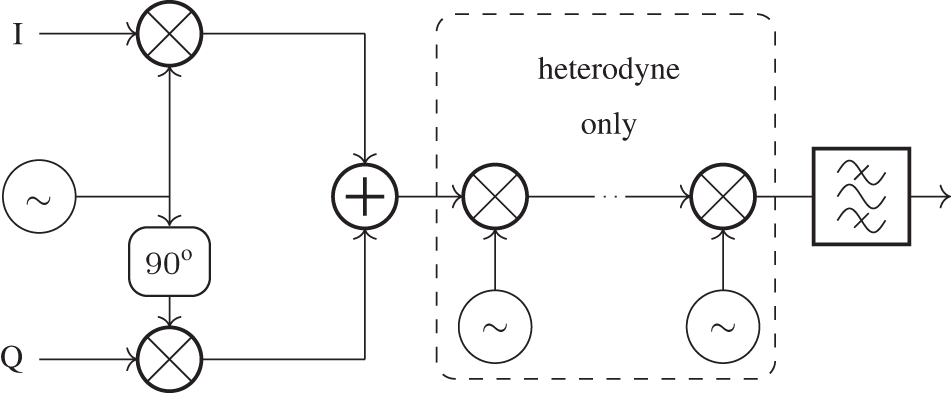
The optoelectronic (sub-)THz signal generation is based on a coherent optical transmitter architecture [Reference Nagatsuma14, Reference Nagatsuma17, Reference Kanno18]. The transmitter architecture is illustrated in Fig. 1. The process involves modulating an electronic BB I/Q signal onto an optical carrier through an electro-optic inphase/quadrature (I/Q) modulator. To compensate for the high loss of approximately 30 dB of the modulator, an erbium-doped fiber amplifier (EDFA) is used for successive amplification. An optical bandpass filter is utilized to suppress out-of-band amplified spontaneous emission (ASE) noise generated by the EDFA. For simplicity, the EDFA and bandpass filter are not shown in Fig. 1. To generate the (sub-)THz signal, the optically modulated signal is mixed optoelectronically in an UTC-PD with a second laser that has a frequency offset of the desired THz-carrier frequency [Reference Harter19] and is combined in a 50/50 coupler. This optical mixing process results in the downconversion of the optical signal into the (sub-)THz regime. In general, the system utilizes a variable optical attenuator (VOA) and an additional EDFA (not shown in Fig. 1) to adjust the optimal optical input power to the UTC-PD. This architecture provides flexibility in tuning the (sub-)THz frequency and power by adjusting the laser parameters. Additionally, it can be integrated on a miniaturized photonic chip. Changing the optical amplifiers to semiconductor optical amplifiers allows for hybrid integration together with the photodiode, the modulator, and the 50/50 coupler. However, it is important to point out that the limited responsivity of the UTC-PD presents a challenge for generating (sub-)THz signals around 300 GHz with power levels above −10 dBm [Reference Ishibashi20]. The received power can be increased by using (sub-)THz medium power amplifiers (PAs), directive/high-gain antennas, and plano-convex polytetrafluoroethylene (PTFE) lenses.
Generic optoelectronic terahertz signal generation for data transmission based on heterodyne mixing of two lasers in an uni-traveling-carrier photodiode (UTC-PD). Data are modulated by means of an electro-optic I/Q modulator consisting of two Mach–Zehnder modulators (MZMs) and a  $\pi/2$ phase shifter.

Electronic THz transmitter
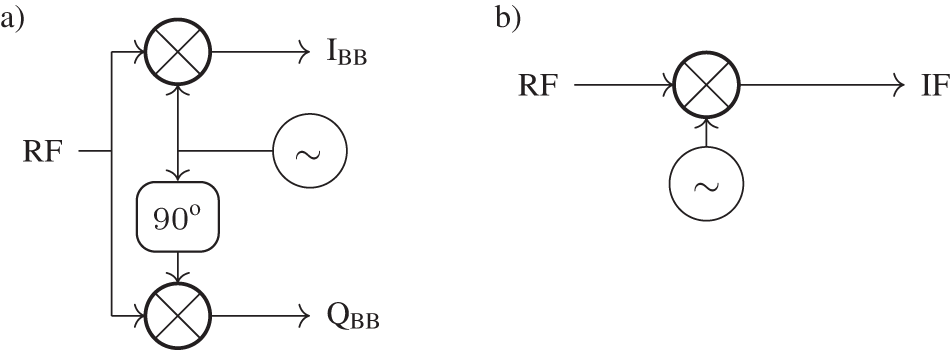
Electronic (sub-)THz transmitters adopt a different signal generation approach. They rely on state-of-the-art radio-frequency (RF) signal generators to create (sub-)THz signals. An electrical BB signal is subsequently upconverted in one or multiple steps to reach the desired (sub-)THz frequency. The specific upconversion method employed depends on the system architecture. For direct conversion, also known as homodyne, a single RF I/Q modulator is sufficient. However, it is essential to generate a high-frequency carrier tone at the desired carrier frequency to accomplish this conversion. Figure 2 illustrates the fundamental setup of such an electronic I/Q modulator. In cases where multiple upconversion stages are combined, known as heterodyne, a lower carrier frequency is required. This approach allows for flexibility in the choice of the initial RF frequencies. However, it also introduces complexity since additional mixers and oscillators are necessary to perform the multiple upconversion steps. These mixers and oscillators are employed to achieve the stepwise frequency transitions from RF to (sub-)THz. To ensure the purity of the generated (sub-)THz signal and to minimize unwanted artifacts, such as harmonics (HMs) and intermodulation products (IMPs), a bandpass filter is typically incorporated into the LO generation system to suppress these unwanted spectral components. This filtering step is crucial for maintaining the signal quality and spectral purity of the generated (sub-)THz wave.
Generic electronic terahertz signal generation based on the combination of the two inphase (I) and quadrature (Q) frequency upconverted signals. Upconversion is based on forward biased nonlinear diodes. In case of a heterodyne transmitter, one or multiple mixing stages are applied.
Intradyne THz receiver
In an intradyne receiver, the incoming modulated (sub-)THz wave is mixed with an LO signal that is close to the (sub-)THz carrier frequency. In this receiver concept, the oscillator is free-running and is not locked in phase and frequency to the transmitter reference oscillator. In contrast homodyne receivers typically involve an analog feedback circuit to lock the LO to the carrier frequency contained in the received signal, while intradyne reception incorporates digital carrier recovery, to reduce the analog circuit complexity and offer higher flexibility. In general, the intradyne receiver generates a complex BB signal with an intermediate frequency (IF) much smaller than the signal bandwidth. The main advantage of an analog BB is the distribution of the signal with a modulation bandwidth B onto two different analog-to-digital converters (ADCs), which need only slightly more than half the signal bandwidth  ${B}/2$ in order to fulfill the Nyquist sampling theorem. As a result, less expensive ADCs can be used for this architecture at the cost of increased receiver complexity. Similarly to the homodyne transmitter (Fig. 2), the (sub-)THz signal is converted to zero IF using two mixing devices with a 90∘ phase offset LO. A basic intradyne receiver with RF input and I/Q BB output is given in Fig. 3(a).
Basic receiver architectures. In subset (a) an intradyne receiver is illustrated. Subset (b) shows a basic heterodyne receiver structure.
Heterodyne THz receiver
Heterodyne receivers use a single nonlinear mixing device and an LO to generate a non-zero IF real-valued signal. To prevent information loss, the requirement for the IF is that it must exceed half of the signal bandwidth. This leads to a less complex receiver, but requires a higher ADC bandwidth to digitize the signal at an IF. In addition, the signal-to-noise ratio is decreased by 3 dB. This is because, during detection, the noise from the image band around the negative IF is folded into the signal if it is not sufficiently suppressed beforehand. Figure 3(b) illustrates a basic heterodyne receiver. A noteworthy single-ended heterodyne scheme is the Kramers–Kronig receiver, previously utilized for achieving record-breaking data transmission at 132 Gbit/s over 110 m [Reference Harter6]. In this scheme, the LO was optically added at the transmitter side, limiting the effective signal power.
THz component modeling
In this section, we mathematically evaluate and model the previously discussed concepts of mixing and LO generation. Firstly, we introduce the fundamental concept of mixing in a nonlinear device. Secondly, we derive the differences between optical and electrical LOs.
Optoelectronic and electronic mixer
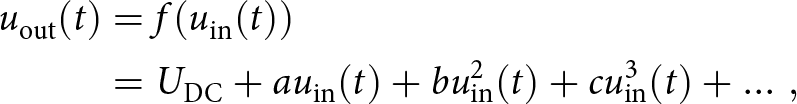
The differences in the performance of electronic and optoelectronic signal generation are based on the fundamental mixing behavior of the two technologies. The idea of mixing is based on exploiting the nonlinear transfer function of a device. In optoelectronic and electronic mixers, the nonlinear characteristics are created by a semiconductor device, such as a diode or transistor, to perform the frequency up- or downconversion [Reference Harter6, Reference Harter21, Reference Dittmer22]. In general, a nonlinear relation between the voltage output  $u_\textrm{out}(t)$ and voltage input $u_\textrm{in}(t)$ of a device can be written as a Taylor series expansion
 \begin{align}
u_\textrm{out}(t) &= f( u_\textrm{in}(t)) \nonumber\\
&= U_\textrm{DC} + a u_\textrm{in}(t) + b u_\textrm{in}^2(t) + cu_\textrm{in}^3(t) + \ldots \, ,
\end{align}
\begin{align}
u_\textrm{out}(t) &= f( u_\textrm{in}(t)) \nonumber\\
&= U_\textrm{DC} + a u_\textrm{in}(t) + b u_\textrm{in}^2(t) + cu_\textrm{in}^3(t) + \ldots \, ,
\end{align} with the coefficients  $a,b,c,\ldots$ depending on the exact nonlinear transfer function and $U_\textrm{DC}$ being a direct-current voltage. For a simple two tone input signal
 \begin{align}
u_\textrm{in}(t) = A \sin{(\omega_1t)} + B \sin{(\omega_2t)} \, ,
\end{align}
\begin{align}
u_\textrm{in}(t) = A \sin{(\omega_1t)} + B \sin{(\omega_2t)} \, ,
\end{align} with arbitrary amplitudes  $A,B$ and frequencies $\omega_1,\omega_2$, the output is
 \begin{align}
u_\textrm{out}(t) &= \,U_\textrm{DC} + a A \sin{(\omega_1t)} + a B \sin{(\omega_2t)} \,+\\
&\dfrac{bA^2}{2}[1-\cos{(2\omega_1t)}] + \dfrac{bB^2}{2}[1-\cos{(2\omega_2t)}]\,+\nonumber\\
&bAB[ \cos{([\omega_2-\omega_1]t)}-\cos{([\omega_2+\omega_1]t)] + \ldots }\,\, .\nonumber
\end{align}
\begin{align}
u_\textrm{out}(t) &= \,U_\textrm{DC} + a A \sin{(\omega_1t)} + a B \sin{(\omega_2t)} \,+\\
&\dfrac{bA^2}{2}[1-\cos{(2\omega_1t)}] + \dfrac{bB^2}{2}[1-\cos{(2\omega_2t)}]\,+\nonumber\\
&bAB[ \cos{([\omega_2-\omega_1]t)}-\cos{([\omega_2+\omega_1]t)] + \ldots }\,\, .\nonumber
\end{align} It consists of the nth harmonics  $n\,\omega_{1}$ and $n\,\omega_{2}$ ( $n \in \mathbb{N}$) as well as the mth intermodulation products $m_1\,\omega_1 \pm m_2 \,\omega_2$ with $m_1 + m_2 = m$ ( $m_1,m_2 \in \mathbb{N}$) of the input frequencies. In electronic transmitters, mixing is performed by the exponential characteristics of diodes and transistors in forward operation. Therefore, the coefficients $a,b,c,\ldots$ are non-zero, which limits the conversion efficiency of the mixer as the power is split between the desired (sub-)THz signal and unwanted HMs and IMPs. Additional signal degradation may occur due to frequency overlap of the (sub-)THz signal with the HMs and IMPs [Reference Dittmer22]. To avoid this interference, customized bandpass filters are required to suppress the unwanted spectral components to a large extent. This filtering, in turn, reduces the efficiency of converting the BB signal to the (sub-)THz domain due to insertion loss and finite stopband attenuation. To compensate for this loss, (sub-)THz amplifiers are frequently used.
Photodiodes, on the other hand, are reverse-biased and result in a square-law detector behavior with respect to the optical input field because the photocurrent is linearly proportional to the optical power. This leaves b ≠ 0 as the only non-zero coefficient, and the output of the mixer consists only of the second-order IMP ( $\omega_1 \,\pm\, \omega_2$) and a signal-to-signal mixing product ( $\omega_1 \,-\, \omega_1$, $\omega_2 \,-\, \omega_2$). This mixing term does not interfere with the (sub-)THz frequencies ( $\omega_1 \,-\, \omega_2$) because it is located in BB. It is inherently filtered out by the bandpass behavior of the (sub-)THz waveguides or antennas. Because it generates fewer unwanted spectral images, the efficiency of a photodiode is higher than that of an electronic diode. However, it is limited by spectral roll-off resulting in lower output powers. Without HM and IMP interferences, the spectral purity of optoelectronically generated signals is much more suitable for broadband, high data rate communications. On the other hand, higher (sub-)THz powers can be generated with electronic signal generation, with output powers in the order of 1 mW compared to 10 µW for optoelectronic approaches [Reference Ishibashi20, Reference Kallfass23].
LO modeling
A general difference in electronic and optoelectronic signal generation is the LO performance in terms of frequency stability, amplitude fluctuation, and phase noise [Reference Cerda24]. Oscillators are used to generate periodic signals that serve as the phase reference for up- and downconversion in mixer circuits. In the case of HM oscillators, the reference signal takes the form of a single sinusoidal tone s(t), at a specific frequency. Most electrical oscillators operate on the basis of a feedback loop that incorporates a frequency-selective filter consisting of capacitors, inductors, and negative resistors through an active device. This combination creates a sustained resonance at the oscillator’s desired frequency, given by  $f_0=1/(2\pi\sqrt{LC})$, where L is the inductance and C is the capacitance. Similarly, lasers are optical oscillators that rely on the concept of resonating photons within an optical cavity to generate coherent light at a predetermined resonant frequency. Within a gain medium, the light undergoes amplification by stimulated emission to produce a sustained oscillating frequency. In practical systems, the sinusoidal signal with amplitude S and frequency $\omega = 2\pi f$ of both oscillator types is additionally affected by amplitude and phase noise, represented as $s_\textrm{n}(t)$ and $\phi_\textrm{n}(t)$, respectively. These noise components lead to a broadening of the signal spectrum, resulting in deviations from the ideal, purely HM behavior [Reference Kouznetsov and Meyer25, Reference Lee and Hajimiri26], i.e.,
 \begin{align}
s(t) &= [S+s_\textrm{n}(t)] \cos(\omega t + \phi_\textrm{n}(t)) \, .
\end{align}
\begin{align}
s(t) &= [S+s_\textrm{n}(t)] \cos(\omega t + \phi_\textrm{n}(t)) \, .
\end{align} Amplitude noise  $s_\textrm{n}(t)$ can be neglected in most cases because LOs (electrically or optically generated) are typically designed with precise control over their amplitude through a feedback control loop [Reference McNeilage27, Reference Kitching28]. A simple model for the phase noise
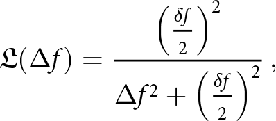
  $\phi_\textrm{n}(t)$ is a Wiener process [Reference Pavliotis29, Reference Kikuchi30], which results in a Lorentzian power spectral density with 3 dB bandwidth $\delta f$ given by [Reference Dittmer22]
 \begin{align}
\mathfrak{L} (\Delta f) &= \dfrac{\left(\frac{\delta f}{2}\right)^2}{\Delta f^2 + \left(\frac{\delta f}{2}\right)^2}\, ,
\end{align}
\begin{align}
\mathfrak{L} (\Delta f) &= \dfrac{\left(\frac{\delta f}{2}\right)^2}{\Delta f^2 + \left(\frac{\delta f}{2}\right)^2}\, ,
\end{align} normalized to  $\mathfrak{L}(\Delta f = 0) = 1$ and $\Delta f$ is the carrier offset frequency [Reference Kundert31]. Phase noise performance of oscillators is commonly evaluated using two primary metrics, linewidth and power spectral density, which provide insights into spectral purity and frequency stability. The linewidth refers to the spectral width of an oscillator’s output signal and is typically measured in units of Hertz. It quantifies the range of frequencies over which the power spectral density of the signal falls to half its peak value (3 dB), often described in terms of full-width at half-maximum, and is inherently used in the Wiener process definition with $\delta f$. A narrower linewidth indicates a higher coherence time, while a wider linewidth indicates greater spectral spread and phase uncertainty. The power spectral noise density, on the other hand, is expressed in dBc/Hz and represents the level of unwanted spectral components at a given offset frequency relative to the carrier signal in a given frequency bandwidth B (typically B = 1 Hz). Linewidth in oscillators reveals the spectral width of a signal, providing insight into coherence and stability. Power spectral noise density indicates the presence of unwanted spectral components, including random fluctuations and spurious signals, that deviate from the ideal sinusoidal carrier relative to the carrier. Assuming a perfect Lorentzian power spectral density the single-sided spectrum can be calculated from the noise power density by [Reference Dittmer22]
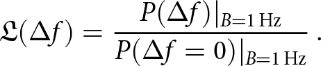
 \begin{align}
\mathfrak{L}(\Delta f) &= \dfrac{P(\Delta f)|_{B = {1}\,\mathrm{Hz}}}{P(\Delta f = 0)|_{B = {1}\,\mathrm{Hz}}} \,.
\end{align}
\begin{align}
\mathfrak{L}(\Delta f) &= \dfrac{P(\Delta f)|_{B = {1}\,\mathrm{Hz}}}{P(\Delta f = 0)|_{B = {1}\,\mathrm{Hz}}} \,.
\end{align} The limited frequency range of electronic oscillators can be overcome by subsequent mixer stages that further upconvert the generated reference tone. However, each upconversion stage increases the phase noise by  $20\log_{10}(N)\,\text{dB}$ [Reference Weber32]. For example, in our scenario, the frequency of the electrical oscillator is 8.33 GHz, which is upconverted to 300 GHz by frequency multiplying by a factor of 36. This increases the phase noise by $20\log_{10}(36) \approx {31}$ dB. For typical electrical oscillators with phase noise in the range of $\mathfrak{L}(\Delta f) = {-111}$ dBc/Hz at an offset frequency of $\Delta f = {1}$ MHz, the increased phase noise corresponds to $\mathfrak{L}(\Delta f) = {-80}$ dBc/Hz. According to the Lorentzian approximation, this is equal to a linewidth of about 200 Hz. This is still considerably less than the linewidth of a sophisticated laser, which is in the order of 1–100 kHz at a wavelength of 1550 nm [Reference Bernhardi33–Reference Maier35]. Fortunately, the impact of phase noise on a communication signal decreases as the symbol rate increases. In addition, the implementation of appropriate receiver-side digital signal processing (DSP) can effectively mitigate phase noise. As a result, phase noise is not a fundamental limitation for high-speed (sub-)THz communication systems that incorporate sophisticated receiver-side DSP [Reference Ip36] as described in “DSP for THz channel and transceiver impairment compensation” section.
Experimental THz communication setup
The assessment of (sub-)THz performance is based on two distinct transmitter and receiver architectures. First, we compare electronic and optoelectronic LO generation by measuring the phase noise. Afterward, the electrical homodyne transmitter is compared to an optoelectronic heterodyne one. Subsequently, an electrical homodyne transmitter was compared to an optoelectronic transmitter based on fiber optic signal generation. Finally, the performance of an intradyne receiver was compared with that of a heterodyne receiver using an optoelectronic (sub-)THz transmitter.
THz LO generation measurement
To assess the performance of the electrically and optoelectronically generated LOs, we measured the phase noise. The single sideband phase noise in 1 Hz of measurement bandwidth (dBc/Hz) of the electrical LO signal is measured at 8.33 GHz [Reference Chen, Ding and Liu37]. In order to generate the desired 300 GHz signal, a frequency multiplication factor of 36 is used, which results in an enhancement of phase noise by a factor of  $20\,\log_{10}(36)=31.13$ dB. The optoelectronically generated LO is measured using a laser with a frequency of 193.5 THz. The downconversion to 300 GHz is accounted for by adding
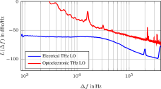
  $20\,\log_{10}(2)=6.02$ dB because of the mixing of two uncorrelated lasers with identical linewidth. Despite the increase in phase noise power for the electronically generated 300 GHz LO compared to its optoelectronically generated counterpart, the resulting phase noise is still 23.1 dBc/Hz lower for offset frequencies above 30 kHz. The measured and corrected (sub-)THz LOs phase noise power spectra are plotted in Fig 4. This evaluation states that the phase noise of the optically generated (sub-)THz LO signal is higher than that of the electrically generated LO signal.
Oscillator phase noise measurement for the upconverted 8.33 GHz electrical (sub-)THz oscillator and the optoelectronically generated (sub-)THz oscillator by beating two lasers in a broadband photodiode. Frequency drift of the local oscillator laser and calibration control loops in the measurement setup (LWA-1k 1550, HighFinesse) result in reliable phase noise estimates only above 3 kHz.
Electronic homodyne transmitter
In the first phase of our evaluation, we examine the performance of a (sub-)THz transmission system using an electrical (sub-)THz signal transmitter, as depicted in Fig. 11(c). The (sub-)THz transmitter used in this context is a 300 GHz intradyne millimeter-wave front-end module designed for wireless point-to-point communications by the Fraunhofer Institute for Applied Solid State Physics IAF [Reference Kallfass38]. This transmitter is fed by an external 8.33 GHz signal generated by a synthesizer (Anritsu 68377B) which is frequency multiplied ×12 to produce a 100 GHz tone [Reference Weber32]. An additional isolator (ISO) and a narrow-band bandpass filter are added to suppress unwanted frequency components in the LO generation and to ensure perfect matching between the units by preventing back reflections in the ×12 module. This reduces the generated HM drastically. Within the direct-conversion homodyne monolithic microwave integrated circuit (MMIC) I/Q mixer, the 100 GHz signal undergoes a ×3 frequency multiplication to generate the 300 GHz (sub-)THz carrier. An arbitrary waveform generator (AWG, Keysight M8194A) is used to generate the BB transmit signal. The THz signal is amplified by a three-stage PA in the I/Q transmitter module before being transmitted by a standard WR 3.4 horn antenna (VDI), followed by a PTFE lens (Thorlabs LAT200) to further focus and direct the transmitted beam.
Optoelectronic heterodyne transmitter
In the second (sub-)THz transmitter, electrical I/Q signals are generated by the same AWG (Keysight M8194A) at a sampling rate of 120 GSa/s. These signals are then modulated onto the optical carrier operating around 1550 nm using an electro-optic I/Q modulator (Fujitsu FTM7992HM). The modulated optical signal is systematically amplified to 17.5 dBm using an EDFA (LiComm pOA). To mitigate the out-of-band ASE noise from the EDFA, an optical bandpass filter with a bandwidth of 1 nm is used. In order to downconvert the optical signal to the 300 GHz carrier frequency, it is optoelectronically mixed in a UTC-PD (NTT/NEL J-Band mixer) with the second laser having a 300- $\textrm{GHz}$ frequency offset [Reference Harter19]. A VOA and an additional EDFA (Thorlabs 100P) are used to set the UTC-PD input power to 10 dBm. The (sub-)THz signal is again transmitted using the same WR 3.4 horn antenna and a plano-convex PTFE lens as shown in Fig. 5.
Optoelectronic heterodyne transmitter using a uni-travelling carrier photodiode (UTC-PD) for broadband (sub-)THz signal generation [Reference Dittmer15].

Heterodyne THz receiver with optoelectronically generated LO
The heterodyne receiver with an optoelectronically generated LO, as shown in Fig. 6, is based on a Schottky barrier diode (SBD, VDI ZBD-F40) as a nonlinear (sub-)THz mixing device. The reference mixer tone at 275 GHz is generated by photomixing two low-phase-noise optical tones in an UTC-PD, similarly to the mixing performed in the optoelectronic transmitter. A PTFE lens and a WR 3.4 horn antenna, identical to those used in the transmitter, are used to receive the free-space (sub-)THz wave. Before the (sub-)THz signal is downconverted by the WR 3.4 SBD to an IF of 25 GHz, it is pre-amplified by an H-band (260–340 GHz) low-noise amplifier (LNA, Radiometer Physics H-LNA 250-350). The LO generated by the UTC-PD is added to the amplified received signal in a WR 3.4 waveguide power combiner. The resulting 25 GHz IF signal is amplified by 11 dB with a broadband amplifier (SHF 827A) and captured on a single channel of a real-time oscilloscope (Keysight UXR0804A).
Heterodyne (sub-)THz receiver using a Schottky barrier diode (SBD) for signal downconversion with optoelectronically generated receiver local oscillator (LO) [Reference Dittmer15].

Intradyne THz receiver with electronically generated LO
The second receiver, using the same WR 3.4 horn antenna and PTFE lens, was configured with an electronic intradyne receiver. This receiver is built around a packaged GaAs MMIC, provided by the Fraunhofer Institute for Applied Solid State Physics IAF [Reference Kallfass38]. The primary function of this receiver is to convert the 300 GHz signal directly into a complex BB. This conversion is achieved by using an electrically generated 300- $\textrm{GHz}$ LO tone. The receiving module consists of a frequency tripler as well as an I/Q demodulator and an LNA. The MMIC receiver module is fed by the 100- $\textrm{GHz}$ reference tone [Reference Kallfass23] generated by a signal generator extender (SGX, VDI WR10SGX) frequency multiplier module driven by a 16.66- $\textrm{GHz}$ tone. Again, the performance is enhanced by an ISO and a bandpass filter as well as a variable waveguide attenuator, which are used in the 100- $\textrm{GHz}$ path to optimize power and signal quality. Two channels of the real-time oscilloscope are used in conjunction with two broadband RF amplifiers (SHF 827A) to capture the received I/Q signals. A photograph of the intradyne receiver is shown in Fig. 7.
Intradyne (sub-)THz receiver based on GaAs I/Q receiver MMIC and electronic LO generation [Reference Dittmer15].

DSP for THz channel and transceiver impairment compensation
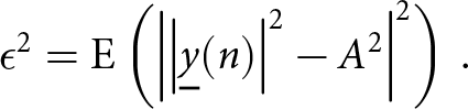
At the transmitter, binary information is mapped to either 4 or 16 complex-valued symbols (QPSK/16 QAM). The transmitted sequence is based on a pseudorandom binary sequence (PRBS15) that has a length of 215–1 bits. The signal, which is upsampled and filtered with a time-domain root-raised-cosine filter having a roll-off factor of r = 0.1, is converted into the analog domain by means of two digital-to-analog converters in order to produce a complex baseband signal. For both, the electronic and optoelectronic (sub-)THz transmitter, the BB signal is modulated onto a single carrier at 300 GHz. Waveforms of 224 samples are recorded at the receiver with the oscilloscope operating at a sampling rate of 256 GSa/s. Subsequently, fully blind digital signal processing algorithms, as depicted in Fig. 8, are applied offline on a PC (i.e., not in real-time). For the heterodyne receiver, the BB signal is generated through digital downconversion of the IF signal to BB. After resampling the waveforms to a nominal value of two samples per symbol, a feedforward timing recovery [Reference Barton and Al-Jalili39, Reference Matalla40], based on the algorithm proposed by Barton & Al-Jalili, is utilized to correct any remaining clock frequency and phase offset between the transmitter and receiver. A time-domain linear equalizer with 51 half-symbol-spaced taps is then used as an adaptive receiving filter. A single output sample is calculated for each symbol and the equalizer coefficients are blindly adjusted using the constant modulus algorithm (CMA). The CMA is a stochastic gradient algorithm that minimizes the radial expected value ( $\textrm{E}$) spread of the equalizer output ϵ [Reference Moshirian41]
 \begin{align}
\epsilon^2 = \textrm{E} \left( \left| \left|\underline{y}(n)\right|^2-A^2\right|^2\right)\, .
\end{align}
\begin{align}
\epsilon^2 = \textrm{E} \left( \left| \left|\underline{y}(n)\right|^2-A^2\right|^2\right)\, .
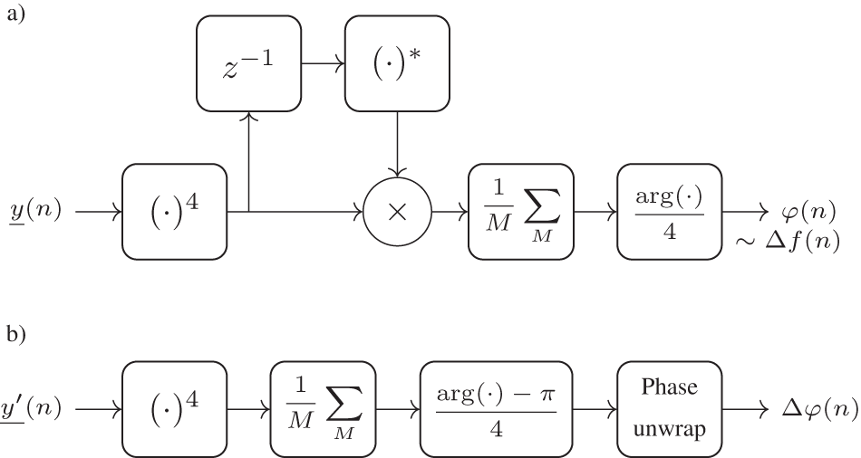
\end{align} With  $\underline{y}(n)$ representing the complex equalizer output and A denoting the intended modulus. The CMA converges before the carrier is recovered due to radial convergence and residual phase uncertainty. To estimate and compensate the frequency offset we use the algorithm proposed in [Reference Leven42]. In a first step, the received samples are raised to the fourth power $(\cdot)^4$ in order to remove the modulation. Next, the result is multiplied with its delayed z −1 and complex conjugated $(\cdot)^*$ version. The outcome is averaged over M symbols to reduce noise. Finally, the frequency offset $\Delta f(n)$ is determined by extracting the resulting argument and dividing it by four. In particular in optoelectronic (sub-)THz communications, it is essential to account for the frequency drifts resulting from the higher frequency variations between the signal and LO laser. After compensating for the frequency offset, the phase noise $\Delta\varphi(n)$ is estimated utilizing the Viterbi–Viterbi algorithm [Reference Viterbi and Viterbi43]. The received symbols are raised to the fourth power
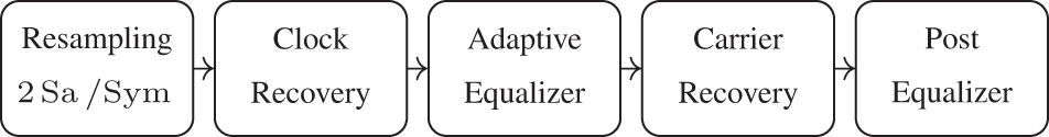
  $(\cdot)^4$ and the resulting phase error is averaged over M = 129 symbols. After unwrapping, a delayed copy of the received symbols is used to compensate for the phase error. The steps for the carrier recovery are shown in Fig. 9. Finally, to compensate for residual I/Q imbalance and skew introduced at the transmitter, a real-valued multiple input multiple output post-equalizer is employed. The coefficients of the equalizer are adapted utilizing the decision-directed least-mean-squares algorithm [Reference Randel44]. The performance of the system is evaluated by making a hard decision on the received symbols and comparing them to the transmitted sequence in order to determine the signal-to-noise-and-distortion ratio (SNDR) and the resulting bit error ratio (BER). While we originally developed our algorithms for QPSK modulation, we have found that they perform reasonably well for 16 QAM and 8 QAM modulation as well.
Receiver digital signal processing chain.
Digital signal processing steps for the carrier recovery. Subset (a) illustrates the frequency offset estimation and (b) the phase noise estimation.
Transceiver evaluation based on measurement results
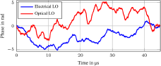
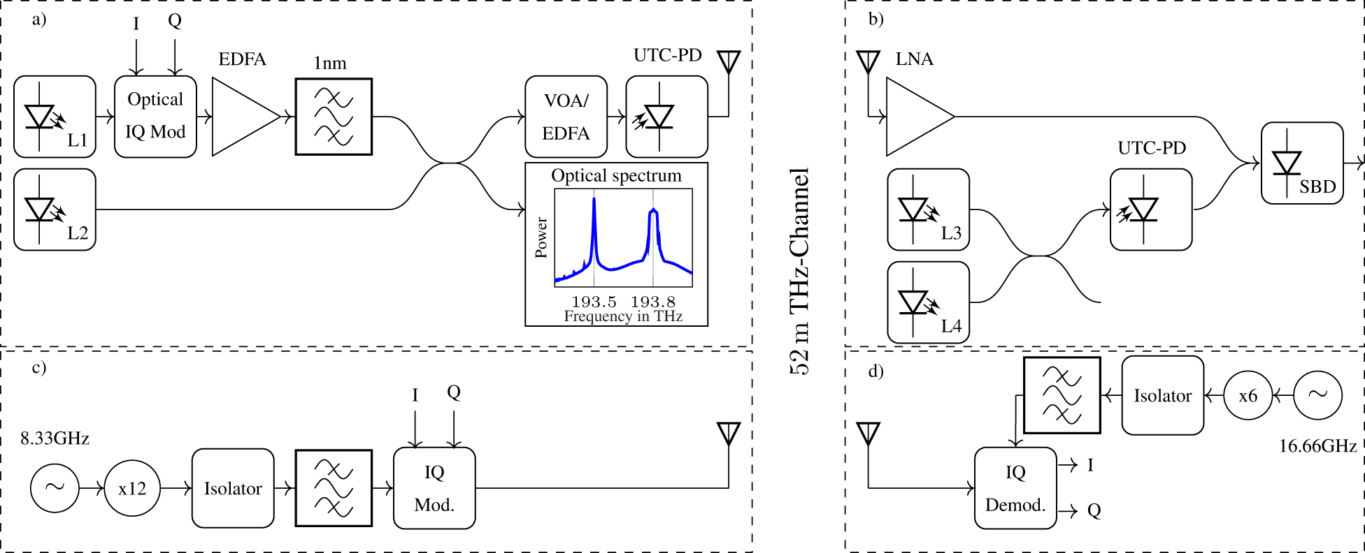
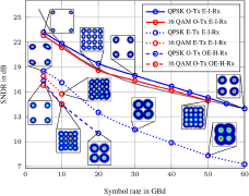
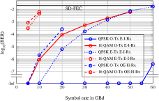
To assess the performance of the optoelectronic and electronic (sub-)THz transmitters in conjunction with the intradyne receiver, which employs an electrically generated 300 GHz LO, and the heterodyne receiver, which utilizes an optically generated 275 GHz LO, a transmission was established in an indoor hallway setting spanning a distance of 52 m. A diagram illustrating the experimental arrangement of the introduced transmitter and receiver concepts is displayed in Fig. 11. First, we compare the phase noise variance between the two proposed receiver schemes, one with optoelectronic LO generation and the other all-electronic. In addition to measuring the linewidth of both LOs depicted in Fig. 4, we transmitted a QPSK signal at 5 GBd and detected it with one of the two receiver schemes. The DSP algorithms described in “DSP for THz channel and transceiver impairment compensation” section are then applied to evaluate the phase noise evolution. Figure 10 shows the estimated carrier phase walk for the optoelectronically and all-electronically generated oscillator tones. As expected, we observe slightly faster variations when the optoelectronic LO is utilized. Blind phase recovery for single-carrier transmission can effectively handle phase noise up to a linewidth-to-symbol-rate ratio of about 10−4, as shown in a previous study [Reference Ip and Kahn45]. This translates to tolerable linewidths of 500 kHz, 3 MHz, and 6 MHz for symbol rates of 5 GBd, 30 GBd, and 60 GBd, respectively. Under a Wiener phase noise model with a Lorentzian power spectrum, the stated values correspond to −52 dBc/Hz, −36.5 dBc/Hz, and −30.5 dBc/Hz at a 100 MHz offset frequency [Reference Dittmer22]. Commercially available lasers and electronic oscillators are capable of meeting these phase noise specifications easily. In our experiment, measurements were conducted under QPSK and 16 QAM schemes, resulting in symbol rates up to 60 GBd, transmitted over the 52 m (sub-)THz link. The findings of the study are presented in Fig. 12. The evaluation of the (sub-)THz link performance is based on the SNDR as a function of symbol rate and the resulting BER. For the combination of an optoelectronic transmitter with an electric intradyne receiver, our measurement performance was particularly noteworthy. For this architecture, a maximum SNDR of 23.2 dB was achieved when operating at a symbol rate of 5 GBd using QPSK as the modulation format. This value exceeds the SNDR of the heterodyne receiver architecture by approximately 6 dB at the same symbol rate. A decrease in performance by 3 dB is expected between intradyne and heterodyne receivers due to the increase in direct detection noise power from the image frequency band. The limited power adjustability of the optically generated LO caused the remaining 3 dB degradation. This results in a suboptimal carrier-to-signal power ratio, leading to a high carrier-carrier beating and a lower intended carrier-signal mixing. Ultimately, this leads to a reduction in SNDR. HMs and IMPs generated in the electronic transmitter reduce the SNDR by about 5 dB compared to the optoelectronically generated (sub-)THz signal. For the 16 QAM modulation scheme, the SNDR performance showed a slight decrease across all transceiver architectures due to nonlinear distortions in the transceiver and less optimal convergence of the DSP algorithms. As expected, the SNDR decreased as symbol rates increased, resulting in a higher BER for all architectures. The overall best performance was achieved with the UTC-PD transmitter and the intradyne coherent receiver. For increased bandwidth, we observed a gradual decrease in SNDR of roughly 10 dB between a symbol rate of 5 GBd and 60 GBd. We attribute this decrease to the increased noise bandwidth in proportion to the symbol rate. These insights underscore the fundamental trade-offs involved in the design of high-speed wireless and wired communication systems. Achieving optimal performance necessitates a careful balance between symbol rate, modulation scheme, and transceiver architecture. By comparing the received and demodulated bit sequence with the transmitted sequence, the BER is calculated. In Fig. 13, we present the resulting values for the three different transceiver architectures based on symbol rate. We assume that the remaining bit errors can be corrected by a forward-error-correction (FEC) scheme. Considering a pre-FEC BER limit of  $2 \times 10^{-2}$ [Reference Agrell and Secondini46] all the bit errors measured for the optoelectronic and electric transmitter can be corrected. Thus, we have demonstrated a record-breaking line rate of 200 Gbit/s over a 52-m-long (sub-)THz link by receiving a 50-
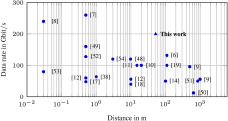
 $\textrm{GBd}$ 16 QAM signal with the optoelectronic transmitter and the intradyne receiver. For the heterodyne receiver, the achievable symbol rate is limited to 10 GBd for 16 QAM and 20 GBd for QPSK. This corresponds to a bit rate of 40 Gbit/s. For the electronic transmitter, a maximum of 120 Gbit/s was achieved by transmitting a 60 GBd QPSK modulated symbol sequence. To conclude the experimental findings, we can state that electronic approaches, while offering the potential for monolithic integration, are plagued by spurious tones due to higher order nonlinearities that reduce the SNDR. In contrast, optoelectronic (sub-)THz generation, exploiting the square-law nonlinearity found in components such as UTC-PDs, results in improved signal integrity. In addition, the availability of mature electro-optic components from fiber optics, including lasers and high-bandwidth electro-optic modulators increases the commercial appeal of optoelectronic solutions. In addition, greater frequency agility in optoelectronic signal generation can enable frequency-based beam steering, e.g., in leaky wave antennas, in a fixed-to-mobile communication application. To overcome the challenge of free-space path loss at such high carrier frequencies, which scales with both the square of the distance and the square of the carrier frequency, highly directional antennas are used for successful transmission over long distances, typically requiring precise alignment of the transmit and receive antennas. Consequently, long-distance (sub-)THz transmission is primarily suited for fixed-to-fixed communication links [Reference Harter21]. As demonstrated in this work, a line rate of 200 Gbit/s represents a new record for a distance of 52 m. It is worth noting that higher line rates have only been achieved over distances of less than 2 m, therefore, limiting their applications in communication [Reference Pang7, Reference Maekawa8]. The different line rates at different distances of previous works [Reference Harter6–Reference Dan12, Reference Nagatsuma14, Reference Nagatsuma17–Reference Harter19, Reference Kallfass38, Reference Nellen47–Reference Mecozzi, Antonelli and Shtaif53] are shown in Fig. 14. Transmission rates at distances exceeding 30 m typically fall within the range of 150 Gbit/s and below [Reference Harter6, Reference Castro9–Reference Nagatsuma14].
Exemplary phase noise evolution estimated on one sample per symbol for an electrically and optically generated local oscillator at the receiver [Reference Dittmer15].
Transmission setup: In subset (a), the photonic transmitter is depicted, comprising two lasers, L1 and L2, an optoelectronic I/Q modulator, an erbium-doped fiber amplifier (EDFA), a 3 dB coupler, a variable optical attenuator (VOA), and an uni-traveling carrier photodiode (UTC-PD). Subset (b) illustrates the photonic single-ended heterodyne receiver, which includes two lasers, L3 and L4, an optical and an electrical 3 dB coupler, an UTC-PD, a SBD, and a low noise amplifier (LNA). The electronic transmitter is illustrated in (c). It consists of an integrated MMIC modulator and power amplifier (PA) pumped by an electrical 8.33 GHz oscillator. In subset (d), the intradyne receiver is presented, featuring an integrated MMIC demodulator and LNA, an electrical 16.666 GHz oscillator, a ×6 VDI-SGX frequency extender, an isolator, and a bandpass filter. The inset spectrum in subset (a) displays the optical power spectrum in front of the UTC-PD.
Measured signal-to-noise-and-distortion ratio (SNDR) after digital signal processing for optoelectronic (OE) transmitter (Tx) with intradyne (I) all-electric (E) and heterodyne (H) optoelectronic (OE) generated local oscillator receiver (Rx). For the all-electric transmitter (Tx) the coherent all-electric (E) intradyne (I) receiver (Rx) is used. The gray line indicates the SNDR reduction caused by increasing signal bandwidth.
Measured bit error ratios versus symbol rate for QPSK and 16 QAM using the optoelectronic (OE) transmitter (Tx) with intradyne (I) all-electric (E) and heterodyne (H) optoelectronic (OE) generated local oscillator receiver (Rx). In addition the all-electric transmitter (Tx) is combined with the coherent all-electric (E) intradyne (I) receiver (Rx).
Measured data rates at (sub-)THz frequencies for various distances according to their publications.
Summary
Based on our analytical and experimental results comparing optoelectronic and electric (sub-)THz signal generation, we concluded that the optoelectronic generation is advantageous when using mature electro-optic modulators in combination with an ultra-broadband square-law detector. This combination results in a relatively clear transmitted signal. Integration of an electronic intradyne receiver MMIC and blind feedforward DSP results in a record-high data rate of 200 Gbit/s at a carrier frequency of 300 GHz using a single carrier modulation. It is noteworthy that the performance was roughly 5 dB lower with an electronic intradyne transmitter due to its higher nonlinearity and HMs causing bandwidth limiting effects. For the indoor fixed-to-fixed transmission experiment the distance was limited to 52 m. Nevertheless, incorporating a (sub-)THz PA at the transmitter has the potential to extend these distances up to 200 m and more. To potentially simplify the receiver structure, we examined a single-ended heterodyne scheme that includes a novel, optoelectronically generated LO technique at the receiver. Our findings indicate a roughly 6 dB reduction in SNDR with this receiver configuration. Nonetheless, the adverse effect can be improved through optimization of the LO-to-signal power ratio and including supplementary Kramers–Kronig signal processing in the receiver structure [Reference Harter6, Reference Mecozzi, Antonelli and Shtaif53]. Our study highlights that even with the use of an optoelectronically generated LO, phase noise does not pose a significant limitation when modern digital phase-recovery algorithms are utilized. The analytical and experimental holistic comparison of optoelectronic and all-electric signal generation under comparable conditions presented in this work can serve as a guideline for future fundamental design considerations for sixth-generation high-capacity fixed-to-fixed (sub-)THz mobile networks.
Acknowledgements
This work is supported by the BMBF projects Open6GHub (S.R. and C.K., grant 16KISK010 and A.S., grant 16KISK017) and 6GEM (A.S., grant 16KISK039) and by the European Research Council (C.K., ERC Consolidator Grant “TeraSHAPE”, #773248). We thank the Fraunhofer Institute for Applied Solid State Physics IAF for providing the MMIC THz hardware.
Competing interests
The author(s) report no competing interests.

Joel Dittmer was born in Karlsruhe, Germany, in 1995. He received the B.Sc. and M.Sc. degrees in electrical engineering from the Karlsruhe Institute of Technology, Karlsruhe, Germany, in 2020 and 2022, respectively. He joined the Institute of Photonics and Quantum Electronics (IPQ) at the Karlsruhe Institute of Technology in 2023, where he started as a research assistant in the field of optoelectronic and electronic generated terahertz signals for wireless communications. His research interests include THz system design, THz package design, and high data rate digital signal processing.

Jonas Tebart received the B.Sc. and M.Sc. degrees in electrical engineering and information technology from the University of Duisburg-Essen, Duisburg, Germany, in 2016 and 2019, respectively, where he is currently pursuing the Ph.D. degree under the supervision of Prof. Andreas Stöhr. After his studies with focus on microelectronics and optoelectronics, he joined the Department of Optoelectronics, University of Duisburg-Essen, as a Research Assistant. His research interests include radio-over-fiber (RoF) techniques, millimeter-wave (mm-wave), and THz communications, 5G, B5G and 6G mobile networks, photonic radars, as well as mm-wave beam-steering antennas.

Patrick Matalla received the B.Sc. and M.Sc. degrees in electrical engineering from the Karlsruhe Institute of Technology, Karlsruhe, Germany, in 2018 and 2020, respectively. He joined the Institute of Photonics and Quantum Electronics (IPQ) at the Karlsruhe Institute of Technology in 2020, where he is currently working toward his Ph.D. degree. His research interests include optical communication systems and the hardware implementation of digital signal processing algorithms on field-programmable gate arrays (FPGAs).

Sandrine Wagner received a B.Sc. in electronics and informatics from the University of Mulhouse, France in 1989. She joined Micronas GmbH in Freiburg, Germany in 1989 where she was responsible for layout and physical verification of large scale integrated semi-conductor devices. In 2010 she joined the Fraunhofer Institute for Applied Solid State Physics (IAF), Freiburg, Germany. Her main interest is the measurement of high frequency nonlinear circuits.

Axel Tessmann received the Dipl.-Ing. degree in electrical engineering from the University of Karlsruhe, Germany, in 1997 and the Ph.D. degree in electrical engineering from the University of Karlsruhe, Germany, in 2006. In 1997, he joined the Microelectronics Department, Fraunhofer Institute for Applied Solid State Physics (IAF), Freiburg, Germany, where he is involved in the development of monolithically integrated circuits and subsystems for high-resolution imaging systems and high data rate wireless communication links. His main research areas are the design and packaging of millimeter-wave and submillimeter wave ICs as well as circuit simulation and linear and nonlinear device modeling. He is currently Group Manager of the millimeter wave packaging and subsystem group at the Fraunhofer IAF.

Akanksha Bhutani earned her M.Sc. and Ph.D. in electrical engineering and information technology from the Karlsruhe Institute of Technology (KIT), Germany, in 2012 and 2019, respectively. Since 2019, she has been leading the Antennas and Packaging research group at KIT’s Institute of Radio Frequency Engineering and Electronics. Her work focuses on THz antennas and packaging for radar and wireless communication. Bhutani’s accolades include the “Carl Freundenberg Prize” and the “Südwestmetall Advancement Award” for her dissertation in 2019 and 2020, the IEEE Microwave Magazine Best Paper Award in 2017, and the European Microwave Week (EuMW) Best Paper Awards in 2019 and 2022 and the International IHP “Wolfgang Mehr” Fellowship Award by the Leibniz-Institut für innovative Mikroelektronik (IHP) in 2023. In 2023, she served as the Operations Officer of EuMW 2023 held in Berlin. She has authored and co-authored over 50 research papers.

Christian Koos received the Ph.D. (Dr.-Ing.) degree in electrical engineering from the University of Karlsruhe, Karlsruhe, Germany, in 2007. He is currently a full Professor with the Karlsruhe Institute of Technology, Karlsruhe, Germany, where he is heading the Institute of Photonics and Quantum Electronics. He has co-founded several start-up companies, such as Vanguard Photonics GmbH, Vanguard Automation GmbH, SilOriX GmbH, and DeepLight SA. From 2008 to 2010, he was affiliated with the Corporate Research and Technology Department of Carl Zeiss AG in Oberkochen, Germany, where he led the technology forecast in the area of nanotechnology. He is the author of more than 140 journal papers and more than 30 patent families. His research interests include silicon photonics and hybrid integration concepts along with the associated applications in high-speed communications, optical sensing and metrology, and ultra-fast photonic-electronic signal processing. He was the recipient of several research awards and prestigious grants, such as the ERC Starting Grant in 2011 and ERC Consolidator Grant in 2017.

Andreas Stöhr (Senior Member, IEEE) received the Dipl.-Ing. and Dr.-Ing. degrees in electrical engineering from Gerhard-Mercator University, Duisburg, Germany, in 1991 and 1997, respectively. From 1996 to 2013, he was a Research Scientist at the University of Duisburg-Essen (UDE), Duisburg. Between 1998 and 1999, he joined the Communications Research Laboratory, Tokyo, Japan. He was with France Telecom Orange Labs, France, in 2009, and Corning, in 2015. Since 2011, he has been a Professor and the Head of the Center for Semiconductor Technology and Optoelectronics, Optoelectronics Department, UDE. He has authored or coauthored more than 200 papers in journals and conferences. His research interests include III/V integrated microwave photonics and RF photonic integration for millimeterwave and THz communications, measurement systems, and sensing applications. He is Senior Member of the IEEE Photonics and MTT Society, committee member and the chair of a number of international conferences, and the Guest Editor of IEEE/OSA.

Sebastian Randel (Senior Member, IEEE) received the Dr.-Ing. degree for his work on high-speed optical-time-division-multiplexed transmission systems from Technische Universität Berlin, Berlin, Germany, in 2005. He is currently a full Professor with the Karlsruhe Institute of Technology, Karlsruhe, Germany, where he is co-heading the Institute of Photonics and Quantum Electronics. From 2005 to 2010, he was a Research Scientist with Siemens Corporate Technology, Munich, Germany, where he led research and standardization activities in the fields of polymer-optical-fiber communications, visible-light communications, and optical access networks. From 2010 to 2016, he was a Member of Technical Staff with Bell Laboratories, Holmdel, NJ, USA. His current research focuses on high-capacity power-efficient optical and (sub-)THz communication systems and networks.


 Open access