











1. Introduction
The ARC fusion power plant is designed to reliably and cost-effectively produce 400 megawatts of net electricity from fusion (Hillesheim et al. Reference Hillesheim2026). To achieve this, the core plasma of ARC will be heated to over 100 million degrees Celsius – more than 10 times hotter than the centre of the Sun. This high-temperature plasma is separated by a little over a metre ( ${a_{\textit{geo}}}\sim {1.18\,\mathrm{m}}$
) from the nearest solid plasma-facing components (PFCs) of the tokamak, which must be kept below a few thousand degrees Celsius (Ueda et al. Reference Ueda2014; Linke et al. Reference Linke2019). To maintain the temperature gradient from core to edge, a strong magnetic field (
${a_{\textit{geo}}}\sim {1.18\,\mathrm{m}}$
) from the nearest solid plasma-facing components (PFCs) of the tokamak, which must be kept below a few thousand degrees Celsius (Ueda et al. Reference Ueda2014; Linke et al. Reference Linke2019). To maintain the temperature gradient from core to edge, a strong magnetic field ( ${B_{\textit{axis}}}\sim {11.4\,\mathrm{T}}$
) will be used to confine the plasma and 250 MW of heating power (mostly alpha heating from fusion reactions) will be continuously added into the core (Hillesheim et al. Reference Hillesheim2026). Due to stiff ion-temperature-gradient turbulence, the resulting temperature gradient is nevertheless predicted to be relatively flat throughout most of the confined region – and as a consequence, ARC’s fusion power output will strongly depend on gradients in the edge pedestal region (Howard et al. Reference Howard2026). To develop steep gradients in the edge, we need to provide sufficient power to develop and sustain an edge transport barrier in a high-confinement H-mode (Wagner et al. Reference Wagner1982; Wagner Reference Wagner2007). Based on empirical scalings (Martin, Takizuka & the ITPA CDBM H-Mode Threshold Database Working Group Reference Martin and Takizuka2008; Vincenzi et al. Reference Vincenzi2025; Delabie et al. Reference Delabie2026), the threshold power is estimated to be around
${B_{\textit{axis}}}\sim {11.4\,\mathrm{T}}$
) will be used to confine the plasma and 250 MW of heating power (mostly alpha heating from fusion reactions) will be continuously added into the core (Hillesheim et al. Reference Hillesheim2026). Due to stiff ion-temperature-gradient turbulence, the resulting temperature gradient is nevertheless predicted to be relatively flat throughout most of the confined region – and as a consequence, ARC’s fusion power output will strongly depend on gradients in the edge pedestal region (Howard et al. Reference Howard2026). To develop steep gradients in the edge, we need to provide sufficient power to develop and sustain an edge transport barrier in a high-confinement H-mode (Wagner et al. Reference Wagner1982; Wagner Reference Wagner2007). Based on empirical scalings (Martin, Takizuka & the ITPA CDBM H-Mode Threshold Database Working Group Reference Martin and Takizuka2008; Vincenzi et al. Reference Vincenzi2025; Delabie et al. Reference Delabie2026), the threshold power is estimated to be around ${\sim} 100$
MW for the ARC flattop (Hillesheim et al. Reference Hillesheim2026). Although these threshold-power scalings were derived in terms of the input power minus the change in stored energy, results from highly radiating plasmas indicate that this threshold power needs to reach the separatrix (Hughes et al. Reference Hughes2011; Solano et al. Reference Solano2021) – with performance continuing to improve as the power crossing the separatrix is increased above the threshold by a factor of up to
${\sim} 100$
MW for the ARC flattop (Hillesheim et al. Reference Hillesheim2026). Although these threshold-power scalings were derived in terms of the input power minus the change in stored energy, results from highly radiating plasmas indicate that this threshold power needs to reach the separatrix (Hughes et al. Reference Hughes2011; Solano et al. Reference Solano2021) – with performance continuing to improve as the power crossing the separatrix is increased above the threshold by a factor of up to ${P_{\textit{sep}}}/{P_{L-H}}\sim 1.5$
(Hughes et al. Reference Hughes2011).
${P_{\textit{sep}}}/{P_{L-H}}\sim 1.5$
(Hughes et al. Reference Hughes2011).
Once the power crosses the separatrix it reaches the scrape-off-layer (SOL) where magnetic field lines intersect the solid walls of the divertor (Pitcher & Stangeby Reference Pitcher and Stangeby1997). Since the power is being carried by plasma particles, it streams much more quickly along than across the magnetic field lines, and this is true also in the SOL. As a consequence, without additional power dissipation, most of the power crossing the separatrix arrives at the divertor surface in a narrow channel (Eich et al. Reference Eich2011; Goldston Reference Goldston2012; Eich et al. Reference Eich2013), leading to a concentrated heat flux that can cause melting or cracking of the divertor surface (Linke et al. Reference Linke2019). Even if the power dissipation is sufficient to avoid melting or cracking, high-energy plasma ions can sputter atoms from the divertor surface, over time leading to material erosion (Hakola et al. Reference Hakola2021) and an increased risk of UFO disruptions (Maget et al. Reference Maget2025). In addition, typical high-performance H-modes periodically release bursts of energy called edge-localised modes (ELMs) (Zohm Reference Zohm1996; Wilson et al. Reference Wilson2006). Large type-I ELMs can melt and displace significant amounts of material from the divertor surface of existing devices such as JET (Coenen et al. Reference Coenen2015), and they are predicted to have even higher-energy fluences in tokamaks with higher pedestal pressures (Eich et al. Reference Eich2017), making them a significant concern for ARC. As well as having to deal with power exhaust, the edge and divertor must also exhaust helium ash and other impurity particles at a sufficient rate to prevent fuel dilution in the core (Reiter et al. Reference Reiter1991).
A poloidal cross-section of the ARC V3A design, highlighting key regions and terminology used in this paper. Note that the engineering design is not final.

Protecting PFCs from continuous and transient heat fluxes while maximising core fusion performance has been recognised as a critical challenge for several fusion power plant designs (Zohm et al. Reference Zohm2021); Asakura et al. Reference Asakura2021, Reference Asakura2023). As a result, these topics have been a key research focus for the international fusion community (Federici et al. Reference Federici2001), and significant progress has been made in the development of highly dissipative and small- or no-ELM scenarios (Campbell et al. Reference Campbell2025; Fenstermacher et al. Reference Fenstermacher2025; Krieger et al. Reference Krieger2025). Experiments on existing tokamaks have shown that, through the controlled injection of impurities such as neon or argon, power can be dissipated from the primary heat exhaust channel and spread across a much larger area of the wall. Impurity seeding has proven to be highly effective at protecting against steady-state heat fluxes on several tokamaks (Kallenbach et al. Reference Kallenbach2011; Xu et al. Reference Xu2020) and may also reduce transient heat fluxes (Komm et al. Reference Komm2023). However, due to their higher mass and charge, impurities can significantly increase the rate at which particles are sputtered from the PFCs (van Rooij et al. Reference van Rooij2013). To prevent sputtering and erosion of the divertor targets, additional power dissipation can be used to cool the SOL plasma to the point where it recombines into neutral gas and detaches from the divertor targets (Krasheninnikov & Kukushkin Reference Krasheninnikov and Kukushkin2017). Detachment greatly reduces divertor sputtering, but needs to be controlled to prevent excessive edge cooling which can reduce confinement or trigger disruptions (Lipschultz Reference Lipschultz1987; Li et al. Reference Li2021). Active detachment control has been successfully demonstrated on several tokamaks including TCV, EAST, KSTAR and DIII-D (Eldon et al. Reference Eldon2021, Reference Eldon2022; Ravensbergen et al. Reference Ravensbergen2021; Wang et al. Reference Wang2022), and significant effort has gone into improving passive detachment stability and compatibility with core performance through optimisation of the divertor magnetic geometry (Soukhanovskii Reference Soukhanovskii2017; Verhaegh et al. Reference Verhaegh2025) and physical neutral baffling (Wang et al. Reference Wang2021; Gao et al. Reference Gao2023; Maurizio et al. Reference Maurizio2024; Meng et al. Reference Meng2024).
Detachment protects against sputtering, melting and cracking of the divertor targets due to the near-steady-state power crossing the separatrix, but large power transients such as type-I-ELMs can burn through the neutral gas layer (Flanagan et al. Reference Flanagan2025). To reduce the size of heat-flux transients, scenarios have been developed which produce pedestal pressures approaching those found in typical type-I-ELMy H-modes while avoiding or suppressing large ELMs – including the quasi-continuous exhaust (QCE/type-II ELM) regime (Stober et al. Reference Stober2001; Faitsch et al. Reference Faitsch2023, Reference Faitsch2025; Saibene et al. Reference Saibene2005), grassy ELM regime (Kamada et al. Reference Kamada2000), enhanced D-alpha regime (Greenwald et al. Reference Greenwald1999; Hubbard et al. Reference Hubbard2001), ELM-suppressed X-point radiator regime (Bernert et al. Reference Bernert2020), quiescent H-mode (Burrell et al. Reference Burrell2002) and wide-pedestal quiescent H-mode (Burrell et al. Reference Burrell2020; Ernst et al. Reference Ernst2024), M-mode (Garcia et al. Reference Garcia2024), I-mode (Whyte et al. Reference Whyte2010) and super-I-mode (Song et al. Reference Song2023), as well as scenarios where type-I-ELMs are suppressed via resonant magnetic perturbations (RMPs) (Moyer et al. Reference Moyer2005) or pellet pacing (Lang et al. Reference Lang2004). In parallel, helium exhaust experiments have demonstrated that helium exhaust out of the confined region is typically sufficient for a fusion power plant – while removing and pumping helium from the SOL remains challenging (Wade et al. Reference Wade1995; Bosch et al. Reference Bosch1997; Sakasai et al. Reference Sakasai1999) and the focus of research (Zito et al. Reference Zito2023; Masline, Wigram & Whyte Reference Masline, Wigram and Whyte2025). These results demonstrate that solutions can be found for heat and particle exhaust, albeit not always simultaneously.
The challenge for ARC is to develop an integrated solution that handles the continuous and transient heat fluxes (projected to be higher than those in most existing devices), provides sufficient helium exhaust, maintains high pedestal pressures and remains compatible with long pulses, a high duty cycle and significant material degradation due to neutron fluxes. To find integrated solutions for the ARC design as it evolved through design iterations, we focused on medium-fidelity models either informed by or validated against experimental results from the fusion community. In this work, we present the results of this medium-fidelity workflow for the ARC V3A design point, while results from ongoing higher-fidelity SOLPS-ITER and SOLEDGE3X transport modelling will be presented in later publications. We first predict the continuous and transient heat fluxes for ARC – in §§ 2.1 and 2.3 respectively – applying scalings developed from multi-machine databases. Based on these results, we find that ARC will need to operate with detached divertors to prevent excessive erosion of the divertor targets, and that large type-I-ELMs will need to be either avoided or mitigated. In § 2.4 we test whether we can use detachment to buffer against ELMs, and find that – although type-I-ELMs are likely to burn through the detachment front – smaller ELMs or filaments should be able to be buffered. Based on this, we designed ARC with X-point target divertors to allow for easier detachment access and control. We discuss recent research on passive detachment stability in § 3.1, and how the X-point target configuration aims to maximise detachment stability in 3.2. We then show the divertor design developed for ARC in § 3.3, and discuss ongoing work to optimise this design in § 3.4.
To show that this divertor design leads to a viable heat exhaust solution for ARC, in § 4 we introduce a workflow to assess whether a given core scenario is compatible with detachment. For a range of coupled core and pedestal solutions identified via integrated modelling, we use the ‘extended Lengyel’ model to predict the concentration of argon which we would need to inject into the divertor in order to access detachment, and then calculate the impurity enrichment required to reach a viable core-edge integrated scenario. These results are generally favourable – finding that even at ARC’s maximum fusion performance, we should be able to access detachment with an argon concentration of ${\sim} {0.9\mathrm{\,\%}}$
in the divertor. We then check whether this operational point also has a viable particle exhaust rate in § 5, and show that due to the high predicted divertor neutral pressure of
${\sim} {0.9\mathrm{\,\%}}$
in the divertor. We then check whether this operational point also has a viable particle exhaust rate in § 5, and show that due to the high predicted divertor neutral pressure of ${\sim} {20\,\mathrm{Pa}}$
ARC should be able to limit the core helium concentration to a few per cent. Finally, we discuss several high-performance, type-I-ELM-free regimes being considered for ARC in § 6. Focusing on the QCE regime in § 6.1, we find that at detachment onset, ARC should have sufficient shaping and edge-pressure gradients to access this regime according to a model proposed by Dunne et al. (Reference Dunne2024) – but this result is called into question since the
${\sim} {20\,\mathrm{Pa}}$
ARC should be able to limit the core helium concentration to a few per cent. Finally, we discuss several high-performance, type-I-ELM-free regimes being considered for ARC in § 6. Focusing on the QCE regime in § 6.1, we find that at detachment onset, ARC should have sufficient shaping and edge-pressure gradients to access this regime according to a model proposed by Dunne et al. (Reference Dunne2024) – but this result is called into question since the $\alpha _t$
turbulence parameter does not meet an access criterion empirically determined by Faitsch et al. (Reference Faitsch2023). In summary, our analysis finds that ARC should be able to achieve good core fusion performance while maintaining detachment, limiting core helium accumulation for reasonable impurity enrichment values and potentially intrinsically avoiding type-I-ELMs.
$\alpha _t$
turbulence parameter does not meet an access criterion empirically determined by Faitsch et al. (Reference Faitsch2023). In summary, our analysis finds that ARC should be able to achieve good core fusion performance while maintaining detachment, limiting core helium accumulation for reasonable impurity enrichment values and potentially intrinsically avoiding type-I-ELMs.
2. The challenge of power exhaust for ARC
Fusion power plants need to find a balance between maximising their fusion performance and protecting their PFCs from power exhaust. Tokamaks operating in a high-performance H-mode need to tackle two interconnected challenges: dissipating the inter-ELM heat exhaust and avoiding or mitigating large type-I ELMs. These challenges are already faced by existing tokamaks, which need to carefully design experiments to avoid damaging the device walls and minimise contamination of the core plasma. Compared with these devices, fusion power plants will operate at higher power and for orders of magnitude more cumulative ‘plasma-on’ time, making the need to identify a power exhaust solution even more critical. Finding a viable power exhaust solution and integrating this with a high-performance core will be crucial to the success of ARC. A useful metric for the trade-off between achieving benign SOL conditions and core performance is the separatrix turbulence parameter
 \begin{align} {\alpha _t}&\simeq 3\times 10^{-18} {R_{\textit{axis}}} {q^{2}_{\textit{cyl}}} \frac {{n_{e,u}}}{{T_{e,u}}^2}{Z_{\textit{eff},u}} \approx \frac {{q_{\textit{cyl}}}\boldsymbol{\cdot }{\nu _{e,\textit{edge}}^*}}{100} ,\end{align}
which gives the strength of ballooning instabilities near the separatrix, relative to drift waves (Eich et al. Reference Eich2020). The $\alpha _t$
parameter can be thought of as a normalisation of the separatrix collisionality
$\alpha _t$
parameter can be thought of as a normalisation of the separatrix collisionality $\nu _{e,\textit{edge}}^*$
(Stangeby Reference Stangeby2018), with values typically ranging from
$\nu _{e,\textit{edge}}^*$
(Stangeby Reference Stangeby2018), with values typically ranging from ${\sim} 0.1$
to
${\sim} 0.1$
to ${\sim} 1.0$
for most operating tokamaks. Higher values of
${\sim} 1.0$
for most operating tokamaks. Higher values of $\alpha _t$
tend to indicate more benign power exhaust conditions (when operating in H-mode) for several reasons; higher values of normalised collisionality typically reduce the fraction of pedestal stored energy lost in an ELM (Loarte et al. Reference Loarte2003), small-ELM or filamentary H-modes have been found to require a minimum value of the normalised collisionality (Wolfrum et al. Reference Wolfrum2011; Labit et al. Reference Labit2019; Faitsch et al. Reference Faitsch2023; Miller et al. Reference Miller2025), and (as we discuss in Appendix B) the impurity concentration required to access detachment scales with
$\alpha _t$
tend to indicate more benign power exhaust conditions (when operating in H-mode) for several reasons; higher values of normalised collisionality typically reduce the fraction of pedestal stored energy lost in an ELM (Loarte et al. Reference Loarte2003), small-ELM or filamentary H-modes have been found to require a minimum value of the normalised collisionality (Wolfrum et al. Reference Wolfrum2011; Labit et al. Reference Labit2019; Faitsch et al. Reference Faitsch2023; Miller et al. Reference Miller2025), and (as we discuss in Appendix B) the impurity concentration required to access detachment scales with ${c_z}\propto {\alpha _t}^{-2}$
(Goldston, Reinke & Schwartz Reference Goldston, Reinke and Schwartz2017; Reinke Reference Reinke2017). However, higher values of
${c_z}\propto {\alpha _t}^{-2}$
(Goldston, Reinke & Schwartz Reference Goldston, Reinke and Schwartz2017; Reinke Reference Reinke2017). However, higher values of $\alpha _t$
are also correlated with reduced confinement (Eich et al. Reference Eich2020), higher levels of cross-field transport (LaBombard et al. Reference LaBombard2005)Footnote
1
and eventually either lead to an L-mode back transition or to the H-mode density limit (Goldston Reference Goldston2015; Manz, Eich & Grover Reference Manz, Eich and Grover2023; Manz Reference Manz2025). Therefore, the highest fusion performance in ARC will be found at the minimum value of
$\alpha _t$
are also correlated with reduced confinement (Eich et al. Reference Eich2020), higher levels of cross-field transport (LaBombard et al. Reference LaBombard2005)Footnote
1
and eventually either lead to an L-mode back transition or to the H-mode density limit (Goldston Reference Goldston2015; Manz, Eich & Grover Reference Manz, Eich and Grover2023; Manz Reference Manz2025). Therefore, the highest fusion performance in ARC will be found at the minimum value of $\alpha _t$
that leads to a robust power exhaust solution with stable detachment and without type-I-ELMs.
$\alpha _t$
that leads to a robust power exhaust solution with stable detachment and without type-I-ELMs.
In the remainder of this section, we predict the continuous and transient heat fluxes for ARC. In § 2.1, we show that continuous divertor detachment throughout the flat-top period will be essential to mitigate risks such as tile cracking from thermal stresses, melting from bulk heating and erosion and core pollution from sputtering. In § 2.3, we show that continuous operation with unmitigated type-I ELMs is infeasible, due to increases in the divertor ELM energy density caused by the significantly higher pedestal top pressure (when compared with operating tokamaks) (Eich et al. Reference Eich2017).
2.1. Continuous heat fluxes and the need for detachment
To demonstrate why detachment is required on ARC, we first need to estimate how much heat is entering the SOL during the quasi-steady-state inter-ELM period, and determine the impact this will have on the divertor. The heat flux in the SOL decays exponentially as we move away from the separatrix, with a characteristic scale length $\lambda _{q,u}$
. The parallel heat-flux density in the first
$\lambda _{q,u}$
. The parallel heat-flux density in the first $\lambda _{q,u}$
of the SOL, when measured at the outboard midplane, is expected to be
$\lambda _{q,u}$
of the SOL, when measured at the outboard midplane, is expected to be
 \begin{align} {q_{\parallel ,u}} &= \frac {{P_{\textit{sep}}}(1 - 1/e){f_{\textit{odiv}}}}{2\pi ({R_{\textit{axis}}} + {a_{\textit{geo}}}){\lambda _{q,u}}}\frac {{B_{\textit{tot},u}}}{{B_{pol,u}}} ,\end{align}
where $P_{\textit{sep}}$
is the total power crossing the separatrix, of which we assume a fraction
$P_{\textit{sep}}$
is the total power crossing the separatrix, of which we assume a fraction $f_{\textit{odiv}}$
is directed towards one of the outer divertors. Approximately
$f_{\textit{odiv}}$
is directed towards one of the outer divertors. Approximately ${f_{\textit{odiv}}}\sim 2/3$
of this usually flows towards the outer divertor in tokamaks with a single divertor, but for SPARC and ARC we will assume
${f_{\textit{odiv}}}\sim 2/3$
of this usually flows towards the outer divertor in tokamaks with a single divertor, but for SPARC and ARC we will assume ${f_{\textit{odiv}}}\sim 1/2$
since both devices have two outer divertors (Brunner et al. Reference Brunner2018a
). Of the power directed to one of the divertors, we assume that
${f_{\textit{odiv}}}\sim 1/2$
since both devices have two outer divertors (Brunner et al. Reference Brunner2018a
). Of the power directed to one of the divertors, we assume that $1 - 1/e = 0.63$
of the power is transported in the first
$1 - 1/e = 0.63$
of the power is transported in the first $\lambda _{q,u}$
. This power is assumed to be spread over a ring with a circumference
$\lambda _{q,u}$
. This power is assumed to be spread over a ring with a circumference $2\pi ({R_{\textit{axis}}} + {a_{\textit{geo}}})$
, where
$2\pi ({R_{\textit{axis}}} + {a_{\textit{geo}}})$
, where $R_{\textit{axis}}$
is the major radius and
$R_{\textit{axis}}$
is the major radius and $a_{\textit{geo}}$
is the minor radius. For our initial analysis we use regression 9 from Eich et al. (Reference Eich2013) to estimate the width of the ring
$a_{\textit{geo}}$
is the minor radius. For our initial analysis we use regression 9 from Eich et al. (Reference Eich2013) to estimate the width of the ring
 \begin{align} {\lambda _{q,u}} [\mathrm{mm}] &= 0.70 {B_{\textit{axis}}}[\mathrm{T}]^{-0.77} {q^{1.05}_{95}} {P_{\textit{sep}}}[\mathrm{MW}]^{0.09} ,\end{align}
while in § 4 we calculate $\lambda _{q,u}$
using (4.2) to account for turbulent broadening at higher
$\lambda _{q,u}$
using (4.2) to account for turbulent broadening at higher $\alpha _t$
values. Finally, we multiply by the magnetic field-line pitch at the outboard midplane
$\alpha _t$
values. Finally, we multiply by the magnetic field-line pitch at the outboard midplane $( {{B_{\textit{tot},u}}}/{{B_{pol,u}}})$
to project the heat flux from the poloidal direction to the parallel direction.
$( {{B_{\textit{tot},u}}}/{{B_{pol,u}}})$
to project the heat flux from the poloidal direction to the parallel direction.
In table 1 we compare the heat flux entering the SOL for several existing tokamaks with SPARC and ARC, taking typical values for $P_{\textit{sep}}$
and other machine parameters. Due to their high magnetic fields and plasma currents, both SPARC and ARC are predicted to require higher
$P_{\textit{sep}}$
and other machine parameters. Due to their high magnetic fields and plasma currents, both SPARC and ARC are predicted to require higher $P_{\textit{sep}}$
to stay in H-mode than on existing tokamaks (Reinke Reference Reinke2017; Hillesheim et al. Reference Hillesheim2026), and this power must be exhausted in a narrower
$P_{\textit{sep}}$
to stay in H-mode than on existing tokamaks (Reinke Reference Reinke2017; Hillesheim et al. Reference Hillesheim2026), and this power must be exhausted in a narrower $\lambda _{q,u}$
. As a result, both SPARC and ARC will have higher heat fluxes flowing into the near SOL than what has been seen on existing devices.
$\lambda _{q,u}$
. As a result, both SPARC and ARC will have higher heat fluxes flowing into the near SOL than what has been seen on existing devices.
Representative values used to calculate the unmitigated heat-flux density $q_{\parallel ,u}$
for Alcator C-Mod (Brunner et al. Reference Brunner, LaBombard, Kuang and Terry2018b
; Greenwald et al. (Reference Greenwald2014), ASDEX Upgrade (Zohm et al. Reference Zohm2024), JET (Kappatou et al. Reference Kappatou2025; Rimini, JET Contributors & the EUROfusion Tokamak Exploitation Team Reference Rimini2025), SPARC (Creely et al. Reference Creely2020; Kuang et al. Reference Kuang2020; Body, Hasse & Creely Reference Body, Hasse and Creely2023) and ARC (Hillesheim et al. Reference Hillesheim2026).
$q_{\parallel ,u}$
for Alcator C-Mod (Brunner et al. Reference Brunner, LaBombard, Kuang and Terry2018b
; Greenwald et al. (Reference Greenwald2014), ASDEX Upgrade (Zohm et al. Reference Zohm2024), JET (Kappatou et al. Reference Kappatou2025; Rimini, JET Contributors & the EUROfusion Tokamak Exploitation Team Reference Rimini2025), SPARC (Creely et al. Reference Creely2020; Kuang et al. Reference Kuang2020; Body, Hasse & Creely Reference Body, Hasse and Creely2023) and ARC (Hillesheim et al. Reference Hillesheim2026).

Once in the SOL, plasma will stream along the magnetic field line towards the divertor targets. Some fraction of the heat flux $f_{\textit{pow}}$
will be dissipated from the near-SOL via radiation or due to cross-field transport, or distributed over a larger area via flux expansion, resulting in a reduced heat flux reaching the divertor target
$f_{\textit{pow}}$
will be dissipated from the near-SOL via radiation or due to cross-field transport, or distributed over a larger area via flux expansion, resulting in a reduced heat flux reaching the divertor target
 \begin{align} {q_{\parallel ,t}}&={q_{\parallel ,u}}(1 - {f_{\textit{pow}}})\frac {{R_u}}{{R_t}} ,\end{align}
which corresponds to a wall-normal heat flux
 \begin{align} {q_{\perp ,t}}&={q_{\parallel ,t}}\sin \left (\theta _\perp \right)\!,\end{align}
where $\theta _\perp$
is the angle of incidence between the fieldline and the wall. To allow for machining and assembly tolerances, we assume
$\theta _\perp$
is the angle of incidence between the fieldline and the wall. To allow for machining and assembly tolerances, we assume $\theta _\perp \sim 2.5^{\circ }$
for the following analysis.
$\theta _\perp \sim 2.5^{\circ }$
for the following analysis.
If the wall-normal heat flux $q_{\perp ,t}$
exceeds the rate at which heat flows out of the divertor, the divertor temperature will increase. Sustained heating can lead to top-surface melting of the divertor targets, or cracking due to thermal gradients. The dynamics of target melting and cracking is complex, and depends on the exact design and history of the divertor targets. We take
$q_{\perp ,t}$
exceeds the rate at which heat flows out of the divertor, the divertor temperature will increase. Sustained heating can lead to top-surface melting of the divertor targets, or cracking due to thermal gradients. The dynamics of target melting and cracking is complex, and depends on the exact design and history of the divertor targets. We take ${\sim} {10\,\mathrm{MW\,m}^{-2}}$
as an order-of-magnitude limit at which melting and cracking starts to become a risk. To stay below this limit, we need to dissipate at least
${\sim} {10\,\mathrm{MW\,m}^{-2}}$
as an order-of-magnitude limit at which melting and cracking starts to become a risk. To stay below this limit, we need to dissipate at least $97\mathrm{\,\%}$
of the
$97\mathrm{\,\%}$
of the $8.5\,\mathrm{GW\,m}^{-2}$
entering the near-SOL, which corresponds to a SOL radiation fraction of
$8.5\,\mathrm{GW\,m}^{-2}$
entering the near-SOL, which corresponds to a SOL radiation fraction of ${f_{rad}}=1 - {\lambda _{\textit{INT}}}/{\lambda _{q,u}} (1 - {f_{\textit{pow}}})={88\mathrm{\,\%}}$
if we assume that
${f_{rad}}=1 - {\lambda _{\textit{INT}}}/{\lambda _{q,u}} (1 - {f_{\textit{pow}}})={88\mathrm{\,\%}}$
if we assume that $ {\lambda _{\textit{INT}}}/{\lambda _{q,u}}={4}$
due to cross-field transport in the divertor (see § 4.3). We estimate the sheath-entrance electron temperature using the two-point-model (Stangeby Reference Stangeby2018)
$ {\lambda _{\textit{INT}}}/{\lambda _{q,u}}={4}$
due to cross-field transport in the divertor (see § 4.3). We estimate the sheath-entrance electron temperature using the two-point-model (Stangeby Reference Stangeby2018)
 \begin{align} {T_{e,t}}&=\frac {8{\langle m_i \rangle }}{{\gamma^{2}_{sh}}}\frac {{q^{2}_{\parallel ,t}}}{(1-{f_{\textit{mom}}}){n_{e,u}}({T_{e,u}}+{T_{i,u}})} ,\end{align}
where $\langle m_i \rangle$
is the average ion mass,
$\langle m_i \rangle$
is the average ion mass, ${\gamma _{sh}}\approx 7.5$
is the sheath heat transmission factor,
${\gamma _{sh}}\approx 7.5$
is the sheath heat transmission factor, $1-{f_{\textit{mom}}}$
is the momentum loss,
$1-{f_{\textit{mom}}}$
is the momentum loss, $n_{e,u}$
is the upstream electron density and
$n_{e,u}$
is the upstream electron density and $T_{e,u}$
and
$T_{e,u}$
and $T_{i,u}$
are the upstream electron and ion temperatures. We assume
$T_{i,u}$
are the upstream electron and ion temperatures. We assume ${T_{e,u}}={T_{i,u}}$
and calculate
${T_{e,u}}={T_{i,u}}$
and calculate
 \begin{align} {T_{e,u}} &= \left ( {T^{7/2}_{e,t}} + \frac {7}{2}\frac {{q_{\parallel ,u}} {L_\parallel }}{{\kappa _{e,0}}} \right )^{2/7} \end{align}
from Spitzer–Harm, using ${L_\parallel }={120\,\mathrm{m}}$
(which is slightly less than the
${L_\parallel }={120\,\mathrm{m}}$
(which is slightly less than the ${L_\parallel }=170\,\mathrm{m}$
from the reference equilibrium – see discussion in § 3). If we limit the target heat flux to
${L_\parallel }=170\,\mathrm{m}$
from the reference equilibrium – see discussion in § 3). If we limit the target heat flux to ${\sim} {10\,\mathrm{MW\,m}^{-2}}$
, the sheath-entrance electron temperature will be
${\sim} {10\,\mathrm{MW\,m}^{-2}}$
, the sheath-entrance electron temperature will be ${\sim} {2\,\mathrm{eV}}$
. This implies that the divertor target will need to be detached to avoid target melting and cracking limits.
${\sim} {2\,\mathrm{eV}}$
. This implies that the divertor target will need to be detached to avoid target melting and cracking limits.
A further argument for why detachment is necessary for ARC comes from calculating the net erosion of the divertor targets. To radiate enough power to stay below melting and cracking limits, we will need to inject noble-gas impurities such as neon or argon into the divertor. These impurities have more electrons than the deuterium and tritium fuel ions, which makes them efficient at radiating power at the temperatures predicted for ARC’s SOL. However, due to their higher masses, these impurities will also increase the sputtering rate from the divertor compared with a pure deuterium-tritium plasma, which introduces several risks for ARC. Sputtering increases the concentration of tungsten in the core (especially if the sputtered tungsten originates from the main chamber (Dux et al. Reference Dux2009; Angioni Reference Angioni2025)). Once in the core, tungsten very efficiently radiates power from the confined region, which can reduce the energy confinement in the core or even trigger a radiative collapse (Ostuni et al. Reference Ostuni2022). Sputtered tungsten can also be redeposited in large, poorly attached flakes, which can trigger UFO disruptions when they detach from the walls (Maget et al. Reference Maget2025). Over the lifetime of ARC’s divertor, sustained sputtering from a localised source such as the divertor strike points will also lead to cumulative material erosion. As a rough estimate for how significant erosion might be if we operated ARC with a dissipative-but-not-detached divertor, we calculate what the direct sputtering would be if we increased the sheath-entrance electron temperature to ${\sim} {10\,\mathrm{eV}}$
(corresponding to a target heat flux of
${\sim} {10\,\mathrm{eV}}$
(corresponding to a target heat flux of ${\sim} {20\,\mathrm{MW\,m}^{-2}}$
). Using the sputtering yields shown in figure 2, we see that at
${\sim} {20\,\mathrm{MW\,m}^{-2}}$
). Using the sputtering yields shown in figure 2, we see that at ${T_{e,t}}\sim {10\,\mathrm{eV}}$
deuterium and tritium ions are not expected to contribute significantly to sputtering, but that argon ions will sputter 1 tungsten atom for every
${T_{e,t}}\sim {10\,\mathrm{eV}}$
deuterium and tritium ions are not expected to contribute significantly to sputtering, but that argon ions will sputter 1 tungsten atom for every ${\sim} {8}$
argon ions reaching the target. From the two-point model (Stangeby Reference Stangeby2018), we estimate a main ion particle flux of
${\sim} {8}$
argon ions reaching the target. From the two-point model (Stangeby Reference Stangeby2018), we estimate a main ion particle flux of $6\times 10^{25}\,\mathrm{m^{-2}s^{-1}}$
to the target. If we assume a
$6\times 10^{25}\,\mathrm{m^{-2}s^{-1}}$
to the target. If we assume a ${\sim} 0.5\,\%$
argon concentration is needed for power dissipation, we find a direct sputtering rate of
${\sim} 0.5\,\%$
argon concentration is needed for power dissipation, we find a direct sputtering rate of ${\sim} {4\times 10^{22}\,\mathrm{m^{-2}s^{-1}}}$
. Taking typical values for tungsten’s mass (
${\sim} {4\times 10^{22}\,\mathrm{m^{-2}s^{-1}}}$
. Taking typical values for tungsten’s mass ( $183.8\,\mathrm{amu}$
) and density (
$183.8\,\mathrm{amu}$
) and density ( $19.6 \,\mathrm{g/cm^3}$
), this would correspond to a net erosion of
$19.6 \,\mathrm{g/cm^3}$
), this would correspond to a net erosion of ${\sim} {600\,\mathrm{nm / s}}$
or
${\sim} {600\,\mathrm{nm / s}}$
or ${\sim} {20\,\mathrm{m}}$
per full power year. Of this, we expect about
${\sim} {20\,\mathrm{m}}$
per full power year. Of this, we expect about ${\sim} {94\mathrm{\,\%}}$
of the sputtered tungsten atoms to be redeposited close to their point of origin (Brezinsek et al. Reference Brezinsek2019). Accounting for redeposition, the gross erosion rate is predicted to be
${\sim} {94\mathrm{\,\%}}$
of the sputtered tungsten atoms to be redeposited close to their point of origin (Brezinsek et al. Reference Brezinsek2019). Accounting for redeposition, the gross erosion rate is predicted to be ${\sim} {1\,\mathrm{m}}$
per full power year, which is much more than the feasible thickness of the tungsten armour in the divertor. To limit erosion to reasonable levels, we will operate ARC with detached divertors. By reducing the target electron temperature to
${\sim} {1\,\mathrm{m}}$
per full power year, which is much more than the feasible thickness of the tungsten armour in the divertor. To limit erosion to reasonable levels, we will operate ARC with detached divertors. By reducing the target electron temperature to $\lesssim 2$
eV the sputtering yield will drop by more than three orders of magnitude (see figure 2), and the incident particle flux will drop once the plasma detaches (Krasheninnikov & Kukushkin Reference Krasheninnikov and Kukushkin2017). Detachment will therefore reduce the erosion rate in the divertor to negligible levels, which is consistent with results from higher-fidelity modelling (Lasa et al. Reference Lasa2026).
$\lesssim 2$
eV the sputtering yield will drop by more than three orders of magnitude (see figure 2), and the incident particle flux will drop once the plasma detaches (Krasheninnikov & Kukushkin Reference Krasheninnikov and Kukushkin2017). Detachment will therefore reduce the erosion rate in the divertor to negligible levels, which is consistent with results from higher-fidelity modelling (Lasa et al. Reference Lasa2026).
The number of tungsten atoms sputtered per incident ion (sputtering yield) as a function of sheath-entrance electron temperature, for an ion flux perpendicular to the tungsten surface. The sputtering yield is calculated in terms of sheath-entrance temperatures by assuming the impact energy is approximately $E_{impact}=2T_e+3ZT_e$
. Reproduced with permission from Neu et al. Reference Neu2026.
$E_{impact}=2T_e+3ZT_e$
. Reproduced with permission from Neu et al. Reference Neu2026.

2.2. Other sources of erosion
Once the plasma is detached and divertor sputtering is suppressed, other sources of sputtering will become the dominant contributors to erosion. Charge-exchange neutrals (Verbeek et al. Reference Verbeek1998; Yoshida & Hirooka Reference Yoshida and Hirooka1998; Baumann et al. Reference Baumann2026), $\alpha$
particles (Bauer et al. Reference Bauer1979; Tobita et al. Reference Tobita2003), radio-frequency sheaths (Bobkov et al. Reference Bobkov2011; Chomiczewska et al. Reference Chomiczewska2024) and filamentary transport into the far-SOL (Redl et al. Reference Redl2023; Perillo et al. Reference Perillo2025) will all contribute to sputtering and erosion, primarily from the main chamber (outside of the divertor). These sputtering sources may lead to significant amounts of material migrating from the main chamber to the detached divertor (Stangeby et al. Reference Stangeby2022), both contributing to erosion and producing significant amounts of slag which can increase the risk of disruptions (Stangeby et al. Reference Stangeby2022; Maget et al. Reference Maget2025). To assess the erosion rate due to charge-exchange neutrals, wide-grid transport modelling with SOLEDGE3X (Rivals et al. Reference Rivals2022) is being performed for ARC. This modelling will help to inform the design of the vacuum vessel and to determine the replacement schedule or whether in-situ maintenance will be needed.
$\alpha$
particles (Bauer et al. Reference Bauer1979; Tobita et al. Reference Tobita2003), radio-frequency sheaths (Bobkov et al. Reference Bobkov2011; Chomiczewska et al. Reference Chomiczewska2024) and filamentary transport into the far-SOL (Redl et al. Reference Redl2023; Perillo et al. Reference Perillo2025) will all contribute to sputtering and erosion, primarily from the main chamber (outside of the divertor). These sputtering sources may lead to significant amounts of material migrating from the main chamber to the detached divertor (Stangeby et al. Reference Stangeby2022), both contributing to erosion and producing significant amounts of slag which can increase the risk of disruptions (Stangeby et al. Reference Stangeby2022; Maget et al. Reference Maget2025). To assess the erosion rate due to charge-exchange neutrals, wide-grid transport modelling with SOLEDGE3X (Rivals et al. Reference Rivals2022) is being performed for ARC. This modelling will help to inform the design of the vacuum vessel and to determine the replacement schedule or whether in-situ maintenance will be needed.
2.3. Transient heat fluxes and the need for small-ELM scenarios
In addition to protecting the divertors from the continuous heat flux predicted for ARC, we also need to protect against heat-flux transients which cause the power crossing the separatrix to rapidly increase for a short amount of time. Of these, we focus on ELMs to show why ARC will need to operate in a scenario which avoids large type-I-ELMs. Type-I-ELMs are a natural consequence of operating in a typical high-performance H-mode. To understand why ELMs occur and to discuss how they might be avoided on ARC, it is helpful to first introduce a simplified model of the physics which drives them (Snyder et al. Reference Snyder2011, Reference Snyder2012). In our simple picture, once an edge transport barrier is formed much of the turbulent radial heat and particle fluxes in the edge are suppressed, and pedestal gradients typically rise until they are constrained by the onset of the kinetic ballooning mode. With reduced radial fluxes through the pedestal, the pedestal width and height increase continuously, in turn driving an increasing amount of bootstrap current. This process continues until a non-local magnetohydrodynamics limit is reached: either a pressure-driven medium-to-high toroidal-mode-number ballooning mode, a current-driven low toroidal-mode-number kink-peeling mode, or a coupled peeling-ballooning mode (Snyder et al. Reference Snyder2002; Viezzer Reference Viezzer2018). Once this limit is reached, the pedestal energy is rapidly ejected towards the divertor targets as an ELM (or, in certain circumstances, the non-local mode can saturate leading to quiescent H-mode operation). Despite being short-lived, these ELM events can deposit significant amounts of energy into the divertor, leading to top-surface melting, cracking and a significant (even dominant) fraction of the total sputtering (Brezinsek et al. Reference Brezinsek2019; Krieger et al. Reference Krieger2025).
To quantitatively show why type-I-ELMs need to be avoided on ARC, we use a model for the peak energy fluence to the divertor from Eich et al. (Reference Eich2017). The model assumes that, during an ELM, magnetic field lines connect the pedestal top to the divertor targets, resulting in a rapid energy loss due to parallel transport. The total energy available is estimated from the pedestal top pressure $p_{e,\textit{ped}}$
and plasma volume near the pedestal top, which is assumed to be evenly distributed over the effective area of the divertor targets. For simplicity we assume that
$p_{e,\textit{ped}}$
and plasma volume near the pedestal top, which is assumed to be evenly distributed over the effective area of the divertor targets. For simplicity we assume that ${T_{e,\textit{ped}}} = {T_{i,\textit{ped}}}$
,
${T_{e,\textit{ped}}} = {T_{i,\textit{ped}}}$
, ${Z_{\textit{eff},\textit{ped}}}=1$
,
${Z_{\textit{eff},\textit{ped}}}=1$
, ${R_t}={R_{ped}}={R_{\textit{axis}}}$
to arrive at a simple equation for the energy fluence
${R_t}={R_{ped}}={R_{\textit{axis}}}$
to arrive at a simple equation for the energy fluence
 \begin{align} {\epsilon _\parallel } &\cong C \boldsymbol{\cdot }6\pi \boldsymbol{\cdot }{p_{e,\textit{ped}}} \boldsymbol{\cdot }{R_{\textit{axis}}} \boldsymbol{\cdot }q_{\textit{edge}}, \end{align}
 \begin{align} q_{\textit{edge}}&=\sqrt {\frac {1+{\kappa^{2}_{95}}}{2}}\frac {{a_{\textit{geo}}}}{{R_{\textit{axis}}}}\frac {{B_{tor,u}}}{{B_{pol,u}}} \end{align}
 \begin{align} &=\sqrt {\frac {1+{\kappa^{2}_{95}}}{2}}\frac {{a_{\textit{geo}}}}{{R_{\textit{axis}}} + {a_{\textit{geo}}}}\frac {{B_{\textit{axis}}}}{{B_{pol,u}}}. \end{align}
Despite its simplicity, (2.8) with C = 1 reproduces the minimum $\epsilon _\parallel$
observed on MAST, ASDEX Upgrade and JET (Eich et al. Reference Eich2017), while the largest
$\epsilon _\parallel$
observed on MAST, ASDEX Upgrade and JET (Eich et al. Reference Eich2017), while the largest $\epsilon _\parallel$
was within a factor of 3 of (2.8) for experimental data spanning more than two orders of magnitude of
$\epsilon _\parallel$
was within a factor of 3 of (2.8) for experimental data spanning more than two orders of magnitude of $\epsilon _\parallel$
. Therefore, we expect the type-I-ELM energy fluence to be described by (2.8) for
$\epsilon _\parallel$
. Therefore, we expect the type-I-ELM energy fluence to be described by (2.8) for $C$
between 1 and 3. At the high fusion performance point discussed in § 4, the predicted pedestal pressure for ARC is
$C$
between 1 and 3. At the high fusion performance point discussed in § 4, the predicted pedestal pressure for ARC is $p_{\textit{tot},\textit{ped}}={280\,\mathrm{kPa}}$
(evaluated at one half-width in from the centre of the pedestal tanh fit – this is approximately
$p_{\textit{tot},\textit{ped}}={280\,\mathrm{kPa}}$
(evaluated at one half-width in from the centre of the pedestal tanh fit – this is approximately $28\,\mathrm{\%}$
lower than the pedestal top value, evaluated two half-widths in from the centre of the pedestal tanh fit, used as a boundary condition for core turbulence simulations in Howard et al. (Reference Howard2026)). This gives an electron pressure of
$28\,\mathrm{\%}$
lower than the pedestal top value, evaluated two half-widths in from the centre of the pedestal tanh fit, used as a boundary condition for core turbulence simulations in Howard et al. (Reference Howard2026)). This gives an electron pressure of ${p_{e,\textit{ped}}}={140\,\mathrm{kPa}}$
since we have assumed
${p_{e,\textit{ped}}}={140\,\mathrm{kPa}}$
since we have assumed ${T_{e,\textit{ped}}} \approx {T_{i,\textit{ped}}}$
. Then, taking
${T_{e,\textit{ped}}} \approx {T_{i,\textit{ped}}}$
. Then, taking ${\kappa _{95}}={1.5}$
and
${\kappa _{95}}={1.5}$
and ${B_{pol,u}}={2\,\mathrm{T}}$
from the ARC reference equilibrium and values from table 1, we calculate
${B_{pol,u}}={2\,\mathrm{T}}$
from the ARC reference equilibrium and values from table 1, we calculate $q_{\textit{edge}}={1.5}$
using (2.10). Therefore, we expect a minimum type-I-ELM energy fluence (
$q_{\textit{edge}}={1.5}$
using (2.10). Therefore, we expect a minimum type-I-ELM energy fluence ( $C=1$
) of
$C=1$
) of
 \begin{align} {\epsilon _\parallel } \cong 6\pi \boldsymbol{\cdot }{140\,\mathrm{kPa}} \boldsymbol{\cdot }{4.62\,\mathrm{m}} \boldsymbol{\cdot }{1.5\,\mathrm{}}={18\,\mathrm{MJ\,m}^{-2}} ,\end{align}
which corresponds to target-normal energy fluence of
 \begin{align} {\epsilon _\perp } \cong {\epsilon _\parallel }\sin (2.5^\circ )={0.8\,\mathrm{MJ\,m}^{-2}} \end{align}
and a maximum energy fluence ( $C=3$
) of
$C=3$
) of ${\epsilon _\perp }={2.4\,\mathrm{MJ\,m}^{-2}}$
. To calculate the impact of a type-I-ELM on the divertor targets, we use the analytical ‘free streaming model’ (FSM) (Fundamenski, PITTS & JET EFDA Contributors Reference Fundamenski and Pitts2006). This model describes the energy and particle transport of ELM filaments from the pedestal to the divertor targets, and it has been validated on several tokamaks (Eich et al. Reference Eich2009; Guillemaut et a. Reference Guillemaut2018). Using this model for ARC, we assume the ELM transports ions to the target over a characteristic time scale
${\epsilon _\perp }={2.4\,\mathrm{MJ\,m}^{-2}}$
. To calculate the impact of a type-I-ELM on the divertor targets, we use the analytical ‘free streaming model’ (FSM) (Fundamenski, PITTS & JET EFDA Contributors Reference Fundamenski and Pitts2006). This model describes the energy and particle transport of ELM filaments from the pedestal to the divertor targets, and it has been validated on several tokamaks (Eich et al. Reference Eich2009; Guillemaut et a. Reference Guillemaut2018). Using this model for ARC, we assume the ELM transports ions to the target over a characteristic time scale
 \begin{align} \tau _{\textit{FSM}} &= {L_\parallel }/ \sqrt {({T_{e,\textit{ped}}} + {T_{i,\textit{ped}}})/{\langle m_i \rangle }} \end{align}
set by the parallel connection length and the plasma sound speed at the pedestal top. Using ${L_\parallel }={120\,\mathrm{m}}$
(see § 3) and taking
${L_\parallel }={120\,\mathrm{m}}$
(see § 3) and taking ${T_{e,\textit{ped}}}={T_{i,\textit{ped}}}={4.2\,\mathrm{keV}}$
, we find
${T_{e,\textit{ped}}}={T_{i,\textit{ped}}}={4.2\,\mathrm{keV}}$
, we find $\tau _{\textit{FSM}}={210\,{\unicode{x03BC} }\mathrm{s}}$
. The values of
$\tau _{\textit{FSM}}={210\,{\unicode{x03BC} }\mathrm{s}}$
. The values of $\tau _{\textit{FSM}}$
and
$\tau _{\textit{FSM}}$
and $\epsilon _\perp$
can be used to define a functional form for the ELM energy deposition via an adapted form of the FSM as defined in Eich et al. (Reference Eich2009)
$\epsilon _\perp$
can be used to define a functional form for the ELM energy deposition via an adapted form of the FSM as defined in Eich et al. (Reference Eich2009)
 \begin{align} \begin{split} q_{\textit{ELM}}(t) = 2\boldsymbol{\cdot }\frac {2}{3} \frac {{\epsilon _\perp }}{\sqrt {\pi }} \boldsymbol{\cdot }\left [1 + \left (\frac {\tau _{\textit{FSM}}}{t}\right )^2\right ] \boldsymbol{\cdot }\frac {\tau _{\textit{FSM}}}{t^2} \boldsymbol{\cdot }\mathrm{exp} \left [-\left (\frac {\tau _{\textit{FSM}}}{t} - H_{fl} M_{\parallel ,tor}\right )^2 \right ] \end{split} ,\end{align}
where $H_{fl}$
is a sign variable (−1 or 1) corresponding to the plasma helicity and
$H_{fl}$
is a sign variable (−1 or 1) corresponding to the plasma helicity and $M_{\parallel ,tor}$
is the mach number that arises from the plasma toroidal rotation velocity (for simplicity, we set
$M_{\parallel ,tor}$
is the mach number that arises from the plasma toroidal rotation velocity (for simplicity, we set $M_{\parallel ,tor}=0$
). In this version of the FSM we use the ELM energy fluence instead of the power, and we multiply by an additional factor of two to account for the energy in the full Maxwellian (the original form of this equation from Fundamenski et al. (Reference Fundamenski and Pitts2006) is for a half-Maxwellian (Fundamenski et al. Reference Fundamenski and Pitts2006)). From this, we can calculate the ‘heat-flux factor’ (HFF) due to a type-I-ELM by making a semi-infinite slab approximation and convoluting the time-varying ELM heat pulse with the one-dimensional (1-D) conduction system’s impulse response (or Green’s function) as described in Hu et al. (Reference Hu2024)
$M_{\parallel ,tor}=0$
). In this version of the FSM we use the ELM energy fluence instead of the power, and we multiply by an additional factor of two to account for the energy in the full Maxwellian (the original form of this equation from Fundamenski et al. (Reference Fundamenski and Pitts2006) is for a half-Maxwellian (Fundamenski et al. Reference Fundamenski and Pitts2006)). From this, we can calculate the ‘heat-flux factor’ (HFF) due to a type-I-ELM by making a semi-infinite slab approximation and convoluting the time-varying ELM heat pulse with the one-dimensional (1-D) conduction system’s impulse response (or Green’s function) as described in Hu et al. (Reference Hu2024)
 \begin{equation} \text{HFF}(t) = \frac {1}{2} \int _0^t \frac {q_{\textit{ELM}}(\tau )}{\sqrt {t-\tau }}\text{d}\tau .\end{equation}
As a sanity check, we also calculate the cumulative energy fluence
 \begin{align} {\epsilon _\perp }(t) = \int _0^t q_{\textit{ELM}}(\tau )\text{d}\tau ,\end{align}
which should approach (2.12) for $t\to \infty$
. In figure 3, we show the heat-flux profile, heat-flux factor and cumulative energy fluence calculated for the minimum type-I-ELM energy fluence expected for ARC, corresponding to
$t\to \infty$
. In figure 3, we show the heat-flux profile, heat-flux factor and cumulative energy fluence calculated for the minimum type-I-ELM energy fluence expected for ARC, corresponding to $C=1$
. We find an instantaneous peak heat flux of
$C=1$
. We find an instantaneous peak heat flux of $2.4\,\mathrm{GW\,m}^{-2}$
and a peak heat-flux factor of
$2.4\,\mathrm{GW\,m}^{-2}$
and a peak heat-flux factor of $23\,\mathrm{MJ\,m}^{-2}\,\mathrm{s}^{-0.5}$
for a small (
$23\,\mathrm{MJ\,m}^{-2}\,\mathrm{s}^{-0.5}$
for a small ( $C=1$
) type-I-ELM, and a instantaneous peak heat flux of
$C=1$
) type-I-ELM, and a instantaneous peak heat flux of $7.3\,\mathrm{GW\,m}^{-2}$
and a peak heat-flux factor of
$7.3\,\mathrm{GW\,m}^{-2}$
and a peak heat-flux factor of $70\,\mathrm{MJ\,m}^{-2}\,\mathrm{s}^{-0.5}$
for a large (
$70\,\mathrm{MJ\,m}^{-2}\,\mathrm{s}^{-0.5}$
for a large ( $C=3$
) type-I-ELM on ARC. This is of the order of the material limit for tungsten PFCs of approximately
$C=3$
) type-I-ELM on ARC. This is of the order of the material limit for tungsten PFCs of approximately $50\,\mathrm{MJ\,m}^{-2}\,\mathrm{s}^{-0.5}$
, indicating that type-I-ELMs will either need to be mitigated or completely avoided in ARC.
$50\,\mathrm{MJ\,m}^{-2}\,\mathrm{s}^{-0.5}$
, indicating that type-I-ELMs will either need to be mitigated or completely avoided in ARC.


2.4. Maintaining detachment during heat-flux transients
ARC will operate with detached divertors to limit erosion, which may provide some buffering against transient heat fluxes (Henderson et al. Reference Henderson2023; Komm et al. Reference Komm2023; Flanagan et al. Reference Flanagan2025). Significant reductions in the ELM energy fluences can be achieved via impurity seeding (Komm et al. Reference Komm2023), and if we fully detach the divertors and hold the detachment front away from the divertor targets, the energy cost to ionise the neutral particles should further reduce the ELM energy fluence (Henderson et al. Reference Henderson2023). We can make a rough estimate of how ELMs will interact with a detachment front by estimating the number of neutrals which will be ionised by an ELM and the perpendicular area over which the ELM will deposit its energy. For a transient with a parallel energy fluence of ${\epsilon _\parallel }{}$
, we expect that the parallel length of neutrals ionised by the ELM will be
${\epsilon _\parallel }{}$
, we expect that the parallel length of neutrals ionised by the ELM will be
 \begin{align} L_{\textit{iz}}=\frac {{\epsilon _\parallel }{}}{n_0\boldsymbol{\cdot }\varepsilon _H\boldsymbol{\cdot }\tau _{\textit{resid}}/\tau _{\textit{iz}}} .\end{align}
Taking the divertor neutral pressure of ${20\,\mathrm{Pa}}{}$
calculated in § 4.4, we can calculate the divertor neutral density
${20\,\mathrm{Pa}}{}$
calculated in § 4.4, we can calculate the divertor neutral density $n_{0}=2 {p_{\textit{div}}}/{T_{\textit{wall}}}\approx {3\times 10^{21}\,\mathrm{m^{-3}}}$
(where the factor of two converts from molecular to atomic density). For the hydrogen ionisation energy
$n_{0}=2 {p_{\textit{div}}}/{T_{\textit{wall}}}\approx {3\times 10^{21}\,\mathrm{m^{-3}}}$
(where the factor of two converts from molecular to atomic density). For the hydrogen ionisation energy $\varepsilon _H$
, we can either (conservatively) use the first ionisation potential
$\varepsilon _H$
, we can either (conservatively) use the first ionisation potential $\varepsilon _H=13.6\,\mathrm{eV}$
or (optimistically) an effective ionisation energy
$\varepsilon _H=13.6\,\mathrm{eV}$
or (optimistically) an effective ionisation energy $\varepsilon _H\approx 25\,\mathrm{eV}$
(see § 3.5.2 of Stangeby (Reference Stangeby2000)). For the ratio of the particle residence time to the characteristic ionisation time in the divertor
$\varepsilon _H\approx 25\,\mathrm{eV}$
(see § 3.5.2 of Stangeby (Reference Stangeby2000)). For the ratio of the particle residence time to the characteristic ionisation time in the divertor $\tau _{\textit{resid}}/\tau _{\textit{iz}}$
, we can either (conservatively) use the value of
$\tau _{\textit{resid}}/\tau _{\textit{iz}}$
, we can either (conservatively) use the value of $\tau _{\textit{resid}}/\tau _{\textit{iz}}\sim 30$
for ASDEX-Upgrade from Henderson et al. (Reference Henderson2023) or (optimistically) calculate
$\tau _{\textit{resid}}/\tau _{\textit{iz}}\sim 30$
for ASDEX-Upgrade from Henderson et al. (Reference Henderson2023) or (optimistically) calculate $\tau _{\textit{resid}}/\tau _{\textit{iz}}=({{L_\parallel } n_{e,t} k_{\textit{iz}}({T_{e,t}})}/{\sqrt {2{T_{e,t}}/{\langle m_i \rangle }}})\sim {4000}$
(equation 7 from Henderson et al. (Reference Henderson2023)) using values calculated for ARC in § 4.4. Using conservative assumptions, we calculate that a type-I-ELM with energy fluence in the range
$\tau _{\textit{resid}}/\tau _{\textit{iz}}=({{L_\parallel } n_{e,t} k_{\textit{iz}}({T_{e,t}})}/{\sqrt {2{T_{e,t}}/{\langle m_i \rangle }}})\sim {4000}$
(equation 7 from Henderson et al. (Reference Henderson2023)) using values calculated for ARC in § 4.4. Using conservative assumptions, we calculate that a type-I-ELM with energy fluence in the range ${\epsilon _\parallel }{} = {18\,\mathrm{MJ\,m}^{-2}}$
to
${\epsilon _\parallel }{} = {18\,\mathrm{MJ\,m}^{-2}}$
to $2.4\,\mathrm{MJ\,m}^{-2}$
(
$2.4\,\mathrm{MJ\,m}^{-2}$
( $C=1-3$
) will ionise between
$C=1-3$
) will ionise between $90\,\mathrm{}$
and
$90\,\mathrm{}$
and $300\,\mathrm{m}$
of neutrals, while using optimistic assumptions we find between
$300\,\mathrm{m}$
of neutrals, while using optimistic assumptions we find between $0.4\,\mathrm{}$
and
$0.4\,\mathrm{}$
and $1\,\mathrm{m}$
will be ionised. Compared with the parallel connection length of the divertor
$1\,\mathrm{m}$
will be ionised. Compared with the parallel connection length of the divertor ${L_{\textit{div}}}={73\,\mathrm{m}}$
(see § 3), with conservative assumptions
${L_{\textit{div}}}={73\,\mathrm{m}}$
(see § 3), with conservative assumptions $L_{\textit{iz}}\gt {L_{\textit{div}}}$
which we interpret as implying that ELMs will cause divertor reattachment, while with optimistic assumptions
$L_{\textit{iz}}\gt {L_{\textit{div}}}$
which we interpret as implying that ELMs will cause divertor reattachment, while with optimistic assumptions $L_{\textit{iz}}\ll {L_{\textit{div}}}$
implying that the neutrals in the divertor may be able to absorb the energy of the ELM. However, when we also calculate the radial extent of an ELM by calculating the ELM-wetted area, we find that ELMs will deposit their energy much further into the SOL than the continuous heat exhaust. Using the pedestal values from the previous section, we can calculate the pedestal energy
$L_{\textit{iz}}\ll {L_{\textit{div}}}$
implying that the neutrals in the divertor may be able to absorb the energy of the ELM. However, when we also calculate the radial extent of an ELM by calculating the ELM-wetted area, we find that ELMs will deposit their energy much further into the SOL than the continuous heat exhaust. Using the pedestal values from the previous section, we can calculate the pedestal energy $W_{ped}={3}/{2}{n_{e,\textit{ped}}}({T_{e,\textit{ped}}} + {T_{i,\textit{ped}}})V_{plas}\approx {81\,\mathrm{MJ}}$
(for
$W_{ped}={3}/{2}{n_{e,\textit{ped}}}({T_{e,\textit{ped}}} + {T_{i,\textit{ped}}})V_{plas}\approx {81\,\mathrm{MJ}}$
(for $V_{plas}=189\,\mathrm{m}^{3}$
from Hillesheim et al. (Reference Hillesheim2026)) and the pedestal top collisionality
$V_{plas}=189\,\mathrm{m}^{3}$
from Hillesheim et al. (Reference Hillesheim2026)) and the pedestal top collisionality
 \begin{equation} {\nu _{e,\textit{ped}}^*}=\frac {\pi {q_{\textit{cyl}}} R}{1.03\boldsymbol{\cdot }10^{16}}\frac {{n_{e,\textit{ped}}}}{{T_{e,\textit{ped}}}^2}\,{Z_{\textit{eff},\textit{ped}}}\approx {0.075\mathrm{}} \end{equation}
for $n_{e,\textit{ped}}$
in
$n_{e,\textit{ped}}$
in $\mathrm{m^{-3}}$
and
$\mathrm{m^{-3}}$
and $T_{e,\textit{ped}}$
in
$T_{e,\textit{ped}}$
in $\mathrm{eV}$
, with
$\mathrm{eV}$
, with ${Z_{\textit{eff},\textit{ped}}}=1.7$
. This lets us estimate
${Z_{\textit{eff},\textit{ped}}}=1.7$
. This lets us estimate $\Delta W_{\textit{ELM}}/W_{ped}\approx {10\mathrm{\,\%}}$
using the relationship from figure 11 of Loarte et al. (Reference Loarte2003), and therefore
$\Delta W_{\textit{ELM}}/W_{ped}\approx {10\mathrm{\,\%}}$
using the relationship from figure 11 of Loarte et al. (Reference Loarte2003), and therefore $\Delta W_{\textit{ELM}}\approx {8.1\,\mathrm{MJ}}$
. The radial extent of an ELM can be calculated using
$\Delta W_{\textit{ELM}}\approx {8.1\,\mathrm{MJ}}$
. The radial extent of an ELM can be calculated using
 \begin{equation} \lambda _{q,ELM}=\frac {\Delta W_{\textit{ELM}}}{{\epsilon _\perp }}\times \frac {0.5}{2\pi \,{R_{\textit{axis}}} f_{x}} ,\end{equation}
where the factor of 0.5 accounts for both divertor target plates, and $f_x\approx 6$
is the flux expansion which lets us map from the midplane to the divertor target. Taking
$f_x\approx 6$
is the flux expansion which lets us map from the midplane to the divertor target. Taking $\epsilon _\perp$
for a large (
$\epsilon _\perp$
for a large ( $C=3$
) ELM from the previous section, we calculate
$C=3$
) ELM from the previous section, we calculate $\lambda _{e,ELM}\approx {10\,\mathrm{mm}}$
. This is significantly larger than the inter-ELM heat-flux decay length of approximately
$\lambda _{e,ELM}\approx {10\,\mathrm{mm}}$
. This is significantly larger than the inter-ELM heat-flux decay length of approximately $0.56\,\mathrm{mm}$
(from table 1), implying that type-I-ELMs on ARC will deposit their energy far into the SOL which is typically more challenging to detach than the near-SOL (Kallenbach et al. Reference Kallenbach2015). Therefore, due to both the parallel and perpendicular dynamics, we view buffering type-I-ELMs as too uncertain to be taken as the power exhaust solution for ARC.
$0.56\,\mathrm{mm}$
(from table 1), implying that type-I-ELMs on ARC will deposit their energy far into the SOL which is typically more challenging to detach than the near-SOL (Kallenbach et al. Reference Kallenbach2015). Therefore, due to both the parallel and perpendicular dynamics, we view buffering type-I-ELMs as too uncertain to be taken as the power exhaust solution for ARC.
Nevertheless, it may be possible to buffer against smaller heat exhaust transients such as the filaments which are characteristic of the QCE scenario discussed in § 6.1. Recent work by Perillo et al. (Reference Perillo2026) shows that the energy fluence of small ELMs and filaments can be described by (2.8) by replacing the pedestal top pressure by the pedestal foot pressure. Taking separatrix values computed in § 4, we find that filaments generated near the separatrix should be able to buffered by between $3$
and
$3$
and $8\,\mathrm{m}$
of neutrals using conservative assumptions, which is significantly less than the parallel connection length of the divertor. Therefore, by operating ARC with a detachment front in the divertor leg, we should be able to buffer against smaller ELMs and filaments – providing protection against both the continuous and transient heat fluxes predicted for ARC.
$8\,\mathrm{m}$
of neutrals using conservative assumptions, which is significantly less than the parallel connection length of the divertor. Therefore, by operating ARC with a detachment front in the divertor leg, we should be able to buffer against smaller ELMs and filaments – providing protection against both the continuous and transient heat fluxes predicted for ARC.
3. Designing the ARC divertor
To limit erosion ARC will need to operate with detached divertors, and to provide a sufficient buffer against heat-flux transients the detachment front should be held away from the divertor targets. One option would be to allow the detachment front to reach the primary X-point and control the resulting ‘X-point radiator’ (XPR) (Bernert et al. Reference Bernert2025). However, as discussed in § 6.2, until we can test the performance of the XPR scenario on SPARC, we want to ensure that we can stabilise the detachment front in the divertor leg. In § 3.1, we discuss current experimental results and modelling to identify effects which passively stabilise detachment, and in § 3.2 we introduce the X-point target geometry which maximises these effects. We then present the current divertor design for ARC in § 3.3 and discuss ongoing work to optimise the divertor design in § 3.4.
3.1. Stabilising a detachment front in the divertor leg
Stabilising a detachment front in the divertor leg is challenging. On tokamaks such as ASDEX Upgrade, DIII-D and JET, once the detachment front lifts off the divertor targets, it moves rapidly to the X-point (Lipschultz, Parra & Hutchinson Reference Lipschultz, Parra and Hutchinson2016). Conversely, on MAST-U and TCV it is possible to stabilise the detachment front in the divertor leg (Ravensbergen et al. Reference Ravensbergen2021; Verhaegh et al. Reference Verhaegh2025). Understanding the differences between these tokamaks helps to identify effects which should improve detachment stability in ARC. Firstly, both MAST-U and TCV have carbon walls, and typically have less exhaust power than ASDEX Upgrade, DIII-D and JET. If SPARC experiments find that detachment stabilisation is not possible in a high-powered, metal-walled tokamak, we will need to change our power exhaust solution for ARC. However, in addition to these factors, both MAST-U and TCV can operate in advanced/alternative divertor configurations (such as the ‘X-divertor’ (Kotschenreuther et al. Reference Kotschenreuther2007), ‘super-X’ (Valanju et al. Reference Valanju, Kotschenreuther, Mahajan and Canik2009) and ‘X-point target’ configurations) and with physical baffles to confine neutrals in the divertor leg (Reimerdes et al. Reference Reimerdes2021; Kool et al. Reference Kool2025; Lee et al. Reference Lee2025; Verhaegh et al. Reference Verhaegh2025).
Modelling (Kotschenreuther et al. Reference Kotschenreuther2013; Lipschultz et al. Reference Lipschultz, Parra and Hutchinson2016; Cowley et al. Reference Cowley2022; Carpita et al. Reference Carpita2024) and experimental results (Lee et al. Reference Lee2025; Verhaegh et al. Reference Verhaegh2025) suggest that tightly baffled, long-legged divertors with significant flux expansion may be able to stabilise a detachment front in the divertor leg. A mechanism for this is sketched in figure 4. If the magnetic field strength decreases in the direction of the divertor targets, $q_{\parallel }$
will decrease and the area for plasma–neutral interactions will increase in the direction of the divertor targets. If a detachment front moves towards the divertor target due to a transient increase in
$q_{\parallel }$
will decrease and the area for plasma–neutral interactions will increase in the direction of the divertor targets. If a detachment front moves towards the divertor target due to a transient increase in $P_{\textit{sep}}$
or decrease in
$P_{\textit{sep}}$
or decrease in $n_{e,u}$
or
$n_{e,u}$
or $c_z$
, the rate of power dissipation will increase, pushing the detachment front back towards its original position. Conversely, if a detachment front moves upstream, these effects should act in the opposite direction. Therefore, with sufficient flux expansion in the divertor leg, we should be able to stabilise a detachment front (LaBombard et al. Reference LaBombard2015; Verhaegh et al. Reference Verhaegh2025). However, in TCV experiments, this is only observed with tight divertor baffling (Theiler et al. Reference Theiler2017). Without divertor baffling, strong parallel particle flows form due to neutral ionisation upstream of the X-point (Fil et al. Reference Fil2020; Cowley, Moulton & Lipschultz Reference Cowley, Moulton and Lipschultz2026). These parallel flows shift heat flux from the conductive to the convective channel and increase the static pressure loss from the outboard midplane to the detachment front – reducing the plasma density in front of the detachment front and making it more difficult to access detachment (Carpita et al. Reference Carpita2024; Cowley et al. Reference Carpita2024). By introducing baffles, the benefits of total flux expansion are recovered (Fil et al. Reference Fil2020; Lee et al. Reference Lee2025) – suggesting that a combination of total flux expansion and baffling are needed for stabilising a detachment front (Verhaegh et al. Reference Verhaegh2025).
$c_z$
, the rate of power dissipation will increase, pushing the detachment front back towards its original position. Conversely, if a detachment front moves upstream, these effects should act in the opposite direction. Therefore, with sufficient flux expansion in the divertor leg, we should be able to stabilise a detachment front (LaBombard et al. Reference LaBombard2015; Verhaegh et al. Reference Verhaegh2025). However, in TCV experiments, this is only observed with tight divertor baffling (Theiler et al. Reference Theiler2017). Without divertor baffling, strong parallel particle flows form due to neutral ionisation upstream of the X-point (Fil et al. Reference Fil2020; Cowley, Moulton & Lipschultz Reference Cowley, Moulton and Lipschultz2026). These parallel flows shift heat flux from the conductive to the convective channel and increase the static pressure loss from the outboard midplane to the detachment front – reducing the plasma density in front of the detachment front and making it more difficult to access detachment (Carpita et al. Reference Carpita2024; Cowley et al. Reference Carpita2024). By introducing baffles, the benefits of total flux expansion are recovered (Fil et al. Reference Fil2020; Lee et al. Reference Lee2025) – suggesting that a combination of total flux expansion and baffling are needed for stabilising a detachment front (Verhaegh et al. Reference Verhaegh2025).
The effect of magnetic flux expansion and baffles on detachment stability. Orange circles indicate main ions, green circles indicate neutrals and purple circles indicate a seeded impurity. A gradient in the magnetic field strength will lead to a gradient in $q_{\parallel }$
due to the changing area of the flux tube, and physical baffles cause recycled neutrals to be primarily ionised in the divertor. These effects can passively stabilise a detachment front in the divertor leg, as well as reduce the impurity concentration required to access detachment.
$q_{\parallel }$
due to the changing area of the flux tube, and physical baffles cause recycled neutrals to be primarily ionised in the divertor. These effects can passively stabilise a detachment front in the divertor leg, as well as reduce the impurity concentration required to access detachment.

3.2. The X-point target configuration
The ‘X-point target’ (XPT) advanced divertor geometry aims to maximise the detachment stability of the outer divertor leg by introducing a secondary X-point in the outer divertor leg, close to the outer divertor target (LaBombard et al. Reference LaBombard2013, Reference LaBombard2015).Footnote
2
In a ideal XPT configuration, the secondary X-point is positioned close to the separatrix of the primary X-point, ideally in the SOL common flux region on a flux surface between 0.5 and 1 $\lambda _{q,u}$
into the near-SOL (when mapped back to the outboard midplane). This increases the connection length and flux expansion of the flux tube carrying the maximum heat flux, and may also lead to a redistribution of the heat flux over multiple strike points through strike-point splitting. This configuration was originally proposed for the ADX concept (LaBombard et al. Reference LaBombard2015), for which it was predicted that the XPT would stabilise a detachment front (an ‘X-point MARFE’) at the secondary X-point, leading to passively stable full detachment. In UEDGE simulations of ADX, the XPT configuration allowed for detachment access up to
$\lambda _{q,u}$
into the near-SOL (when mapped back to the outboard midplane). This increases the connection length and flux expansion of the flux tube carrying the maximum heat flux, and may also lead to a redistribution of the heat flux over multiple strike points through strike-point splitting. This configuration was originally proposed for the ADX concept (LaBombard et al. Reference LaBombard2015), for which it was predicted that the XPT would stabilise a detachment front (an ‘X-point MARFE’) at the secondary X-point, leading to passively stable full detachment. In UEDGE simulations of ADX, the XPT configuration allowed for detachment access up to ${\sim} 5-10\times$
higher
${\sim} 5-10\times$
higher $P_{\textit{sep}}$
than for a standard vertical plate divertor (Umansky et al. Reference Umansky2017). In these simulations the detachment front was found to be passively stable, with the stability window increasing with the divertor leg length (Umansky et al. Reference Umansky2020). The XPT was also studied for an earlier design of ARC (Kuang et al. Reference Kuang2018), where UEDGE simulations found that the XPT geometry reduced the target electron temperature by a factor of
$P_{\textit{sep}}$
than for a standard vertical plate divertor (Umansky et al. Reference Umansky2017). In these simulations the detachment front was found to be passively stable, with the stability window increasing with the divertor leg length (Umansky et al. Reference Umansky2020). The XPT was also studied for an earlier design of ARC (Kuang et al. Reference Kuang2018), where UEDGE simulations found that the XPT geometry reduced the target electron temperature by a factor of ${\sim} 10$
relative to a super-X configuration if the primary and secondary X-points were aligned to within
${\sim} 10$
relative to a super-X configuration if the primary and secondary X-points were aligned to within ${\sim} 1.4{\lambda _{q,u}}{}$
(when mapped to the outboard midplane) (Wigram et al. Reference Wigram2019). These simulation results have largely been supported by experimental results from TCV, which find that the XPT geometry reduces the outer divertor sheath-entrance temperature and power flux relative to a conventional divertor configuration or even X and super-X configurations (Raj et al. Reference Raj2022; Lee et al. Reference Lee2025). These experiments also confirmed the prediction of LaBombard et al. (Reference LaBombard2015) that a detachment front could be stabilised at the secondary X-point – observing the formation of an ‘XPT radiator’ similar to an XPR except located at the secondary X-point (Lee et al. Reference Lee2025).
${\sim} 1.4{\lambda _{q,u}}{}$
(when mapped to the outboard midplane) (Wigram et al. Reference Wigram2019). These simulation results have largely been supported by experimental results from TCV, which find that the XPT geometry reduces the outer divertor sheath-entrance temperature and power flux relative to a conventional divertor configuration or even X and super-X configurations (Raj et al. Reference Raj2022; Lee et al. Reference Lee2025). These experiments also confirmed the prediction of LaBombard et al. (Reference LaBombard2015) that a detachment front could be stabilised at the secondary X-point – observing the formation of an ‘XPT radiator’ similar to an XPR except located at the secondary X-point (Lee et al. Reference Lee2025).
3.3. The divertor geometry for the ARC V3A design point
Magnetic field along the near-SOL (surface marked in purple in figure 1, $1\,\mathrm{mm}$
into the SOL when measured at the outboard midplane), from the outboard midplane to the divertor target. The toroidal and poloidal field strengths are marked in orange and blue respectively, with values given at the primary X-point, in the mid-divertor leg and at the secondary X-point.
$1\,\mathrm{mm}$
into the SOL when measured at the outboard midplane), from the outboard midplane to the divertor target. The toroidal and poloidal field strengths are marked in orange and blue respectively, with values given at the primary X-point, in the mid-divertor leg and at the secondary X-point.

To increase the range of upstream conditions for which we can access detachment and improving the passive stability of the detachment front in the divertor leg, we have developed a X-point-target divertor design for ARC. As shown in figure 1 and discussed in Hillesheim et al. (Reference Hillesheim2026), our design features a long, tightly baffled divertor leg, with a secondary X-point in the outer divertor leg. This geometry maximises the total flux expansion from the primary X-point at ${R_{xpt}}={3.9\,\mathrm{m}}$
to the divertor target at
${R_{xpt}}={3.9\,\mathrm{m}}$
to the divertor target at ${R_t}={5.1\,\mathrm{m}}$
by placing the divertor as far radially outwards as possible. As shown in figure 5, at a flux surface
${R_t}={5.1\,\mathrm{m}}$
by placing the divertor as far radially outwards as possible. As shown in figure 5, at a flux surface $1\,\mathrm{mm}$
from the separatrix (when mapped to the outboard midplane), this configuration has a toroidal flux expansion of
$1\,\mathrm{mm}$
from the separatrix (when mapped to the outboard midplane), this configuration has a toroidal flux expansion of ${\sim}$
1.15 and a poloidal flux expansion of
${\sim}$
1.15 and a poloidal flux expansion of ${\sim}$
5.5 between the divertor leg mid-point and the secondary X-point. The secondary X-point also increases the parallel connection length: for the same field line, we find a parallel connection length of
${\sim}$
5.5 between the divertor leg mid-point and the secondary X-point. The secondary X-point also increases the parallel connection length: for the same field line, we find a parallel connection length of $170\,\mathrm{m}$
from the outboard midplane to the divertor target, of which 123 m are in the divertor leg. However, for the calculations in this paper, we decided to reduce the divertor leg length to
$170\,\mathrm{m}$
from the outboard midplane to the divertor target, of which 123 m are in the divertor leg. However, for the calculations in this paper, we decided to reduce the divertor leg length to $73\,\mathrm{m}$
, reducing the total connection length to
$73\,\mathrm{m}$
, reducing the total connection length to $120\,\mathrm{m}$
. This reduction is conservative and accounts for possible challenges in achieving an ideal XPT configuration.
$120\,\mathrm{m}$
. This reduction is conservative and accounts for possible challenges in achieving an ideal XPT configuration.
3.4. Ongoing development of the ARC divertor design
The divertor design will be optimised further in future ARC design iterations. Due to the flexibility afforded by the liquid FLiBe coolant and breeding blanket, the design of the ARC first wall and vacuum vessel can evolve until relatively late in ARC’s design and construction. This means that we can use SPARC experiments to finalise the design of ARC’s divertor, significantly reducing the extrapolation risk of the final design. We note that the first-wall geometry shown in figure 1 is not yet finalised, and will change in future design iterations. One topic of research for setting the wall geometry is determining the optimal width of the divertor leg, since a narrower leg improves neutral baffling at the cost of increasing the heat flux to the baffles. Different options for the magnetic geometry will also be explored. In particular, since the XPT geometry performs similarly to a super-X divertor (SXD) (Valanju et al. Reference Valanju, Kotschenreuther, Mahajan and Canik2009) if the secondary X-point is beyond ${\sim} 1-2{\lambda _{q,u}}$
of the primary separatrix (Wigram et al. Reference Wigram2019), we will explore whether a SXD is sufficient for power exhaust on ARC. A SXD configuration would relax the requirements on magnetic control relative to an XPT. The SXD configuration has been shown to improve heat-flux handling and detachment stability on MAST-U (Kool et al. Reference Kool2025), but it is not yet clear whether this is sufficient for ARC’s increased heat fluxes and long-lifetime requirements.
${\sim} 1-2{\lambda _{q,u}}$
of the primary separatrix (Wigram et al. Reference Wigram2019), we will explore whether a SXD is sufficient for power exhaust on ARC. A SXD configuration would relax the requirements on magnetic control relative to an XPT. The SXD configuration has been shown to improve heat-flux handling and detachment stability on MAST-U (Kool et al. Reference Kool2025), but it is not yet clear whether this is sufficient for ARC’s increased heat fluxes and long-lifetime requirements.
These research questions will be the focus of SPARC’s ‘Advanced Divertor Mission’. This mission will focus on testing integrated divertor scenarios that project well to long pulse operations under power-plant-relevant conditions in SPARC, exploring a variety of magnetic topologies including long-leg designs and advanced topologies like the SXD and XPT (Kuang et al. Reference Kuang2020). To test these divertor solutions under ARC-like plasma conditions, SPARC will run experiments approaching ARC’s ${P_{\textit{sep}}} {B_{\textit{axis}}}/({R_{\textit{axis}}}{n^{2}_{e,u}})$
values, SOL collisionality
${P_{\textit{sep}}} {B_{\textit{axis}}}/({R_{\textit{axis}}}{n^{2}_{e,u}})$
values, SOL collisionality $\nu _{e,\textit{edge}}^*$
and
$\nu _{e,\textit{edge}}^*$
and $\alpha _t$
. These experiments will aim to identify highly dissipative at conditions close to those expected for ARC, focusing on scenarios which can maintain stable detachment at moderate divertor impurity seeding levels, integrated with helium exhaust and a suitable small-ELM scenario. Experimental results from this mission will also provide a critical validation point for high-fidelity SOL models, which – once validated – will be used to further refine the design of ARC’s divertor.
$\alpha _t$
. These experiments will aim to identify highly dissipative at conditions close to those expected for ARC, focusing on scenarios which can maintain stable detachment at moderate divertor impurity seeding levels, integrated with helium exhaust and a suitable small-ELM scenario. Experimental results from this mission will also provide a critical validation point for high-fidelity SOL models, which – once validated – will be used to further refine the design of ARC’s divertor.
4. Detachment-compatible scenarios
The long-legged, tightly baffled XPT divertor design presented in § 3 should increase the range of core-plasma conditions for which we can access detachment, but we still need to check that we can detach a high fusion power scenario for ARC. In § 4.1 we introduce core modelling performed for ARC, focusing on identifying the separatrix density which leads to the highest fusion performance. Then, in §§ 4.2 and 4.3, we introduce the ‘extended Lengyel’ model, which lets us quantitatively calculate the impurity concentration required to access detachment access. We then apply this model in § 4.4 to calculate detachment onset conditions corresponding to different core scenarios, and show that ARC should be able to access detachment with seeding levels comparable to existing tokamaks.
4.1. Calculating the fusion performance versus separatrix density
ARC fusion power versus $n_{e,u}$
, for
$n_{e,u}$
, for $I_{p}$
=10–12 MA, fixed
$I_{p}$
=10–12 MA, fixed ${B_{\textit{axis}}}={11.4\,\mathrm{T}}$
,
${B_{\textit{axis}}}={11.4\,\mathrm{T}}$
, ${q^*}=3.2{-}3.8$
(
${q^*}=3.2{-}3.8$
( ${q_{\textit{cyl}}} = 3.0{-}3.6$
) and a fixed Greenwald density fraction of 0.9.
${q_{\textit{cyl}}} = 3.0{-}3.6$
) and a fixed Greenwald density fraction of 0.9.

A workflow to predict the core performance of ARC scenarios was developed in Howard et al. (Reference Howard2026). This workflow used a neural network trained on EPED (Snyder et al. Reference Snyder2011) simulations of the ARC pedestal over a broad range of conditions, combined with parametrised core profiles inside the pedestal, which allow for the rapid prediction for ARC’s fusion power generation. The results of this workflow were verified against both ASTRA and coupled TRANSP-PORTALS predictions, and found to typically agree within ${\sim} 10\,\%$
. For the results shown in figure 6, we used the core-pedestal modelling workflow to calculate how the fusion power output of ARC varies as a function of the separatrix density. For these simulations we used
${\sim} 10\,\%$
. For the results shown in figure 6, we used the core-pedestal modelling workflow to calculate how the fusion power output of ARC varies as a function of the separatrix density. For these simulations we used ${B_{\textit{axis}}}={11.4\,\mathrm{T}}$
for three different values of
${B_{\textit{axis}}}={11.4\,\mathrm{T}}$
for three different values of $I_{p}$
, for a flat
$I_{p}$
, for a flat $Z_{\textit{eff}}=1.5$
profile (corresponding to a tungsten concentration of
$Z_{\textit{eff}}=1.5$
profile (corresponding to a tungsten concentration of $n_W/n_e=1.5\times 10^{-5}$
and a ‘lumped impurity’ selected to maintain a dilution of
$n_W/n_e=1.5\times 10^{-5}$
and a ‘lumped impurity’ selected to maintain a dilution of $n_{\textit{DT}}/n_e=0.85$
). For each of the three currents, the fusion power increased with density up to the imposed limit of
$n_{\textit{DT}}/n_e=0.85$
). For each of the three currents, the fusion power increased with density up to the imposed limit of $90\,\%$
of the Greenwald density limit (Greenwald et al. Reference Greenwald1988). In figure 6, we show results at 90 % of the density limit and at a separatrix power of
$90\,\%$
of the Greenwald density limit (Greenwald et al. Reference Greenwald1988). In figure 6, we show results at 90 % of the density limit and at a separatrix power of ${P_{\textit{sep}}}={120\,\mathrm{MW}}$
, which is approximately
${P_{\textit{sep}}}={120\,\mathrm{MW}}$
, which is approximately ${P_{\textit{sep}}}/{P_{L-H}}\sim 1.2\times$
the LH threshold power predicted at this density (Hillesheim et al. Reference Hillesheim2026). For each plasma current tested, we varied the ratio of
${P_{\textit{sep}}}/{P_{L-H}}\sim 1.2\times$
the LH threshold power predicted at this density (Hillesheim et al. Reference Hillesheim2026). For each plasma current tested, we varied the ratio of ${n_{e,u}}/{\langle n_e \rangle }$
at fixed
${n_{e,u}}/{\langle n_e \rangle }$
at fixed $\langle n_e \rangle$
to investigate the effect of the separatrix density on core-pedestal performance. We find that the predicted fusion power increases with separatrix density when the pedestal is limited by current-driven peeling modes, until the pedestal reaches the ballooning branch where further increases in the separatrix density cause a significant decrease in the fusion power. Because the core turbulent transport is stiff, pinned near a critical gradient scale length, the variation in the predicted pedestal height with separatrix density is the primary driver of these changes in fusion power.
$\langle n_e \rangle$
to investigate the effect of the separatrix density on core-pedestal performance. We find that the predicted fusion power increases with separatrix density when the pedestal is limited by current-driven peeling modes, until the pedestal reaches the ballooning branch where further increases in the separatrix density cause a significant decrease in the fusion power. Because the core turbulent transport is stiff, pinned near a critical gradient scale length, the variation in the predicted pedestal height with separatrix density is the primary driver of these changes in fusion power.
At the highest plasma current of ${I_{p}}={12\,\mathrm{MA}}$
, the highest fusion power of
${I_{p}}={12\,\mathrm{MA}}$
, the highest fusion power of ${P_{\textit{fus}}}\sim 890\,\mathrm{MW}$
was found at
${P_{\textit{fus}}}\sim 890\,\mathrm{MW}$
was found at ${n_{e,u}}={1\mathrm{\times 10^{20}/m^3}}$
. This is below the
${n_{e,u}}={1\mathrm{\times 10^{20}/m^3}}$
. This is below the $1100\,\mathrm{MW}$
predicted using empirical POPCONs, but consistent with the range of uncertainty of medium-fidelity modelling (Hillesheim et al. Reference Hillesheim2026; Howard et al. Reference Howard2026). As noted in Hillesheim et al. (Reference Hillesheim2026), one path to increasing the fusion power output would be to operate with a Greenwald fraction higher than
$1100\,\mathrm{MW}$
predicted using empirical POPCONs, but consistent with the range of uncertainty of medium-fidelity modelling (Hillesheim et al. Reference Hillesheim2026; Howard et al. Reference Howard2026). As noted in Hillesheim et al. (Reference Hillesheim2026), one path to increasing the fusion power output would be to operate with a Greenwald fraction higher than $90\,\%$
, which would have the added benefit of reducing the impurity concentration required to access detachment. Compared with the
$90\,\%$
, which would have the added benefit of reducing the impurity concentration required to access detachment. Compared with the ${I_{p}}=12\,\mathrm{MA}$ ${P_{\textit{fus}}}\sim 890\,\mathrm{MW}$
, at
${P_{\textit{fus}}}\sim 890\,\mathrm{MW}$
, at ${I_{p}}=11\,\mathrm{MA}$
the maximum fusion power reduces to 780 MW at
${I_{p}}=11\,\mathrm{MA}$
the maximum fusion power reduces to 780 MW at ${n_{e,u}}=1.1\,\mathrm{\times 10^{20}m^{-3}}$
and at
${n_{e,u}}=1.1\,\mathrm{\times 10^{20}m^{-3}}$
and at ${I_{p}}=10\,\mathrm{MA}$
the maximum fusion power reduces to 700 MW at
${I_{p}}=10\,\mathrm{MA}$
the maximum fusion power reduces to 700 MW at ${n_{e,u}}=1.4\mathrm{\times 10^{20}m^{-3}}$
. Interestingly, the reduction in maximum fusion power from
${n_{e,u}}=1.4\mathrm{\times 10^{20}m^{-3}}$
. Interestingly, the reduction in maximum fusion power from ${I_{p}}=12\,\mathrm{MA}$
to
${I_{p}}=12\,\mathrm{MA}$
to ${I_{p}}=10\,\mathrm{MA}$
is a factor of 1.26, which is less than the factor
${I_{p}}=10\,\mathrm{MA}$
is a factor of 1.26, which is less than the factor $1.2^2=1.44$
reduction that would be expected due to the reduction in the Greenwald density limit. The shift to higher separatrix density at reduced current will reduce the impurity concentration required to access detachment, and as such operating at slightly reduced
$1.2^2=1.44$
reduction that would be expected due to the reduction in the Greenwald density limit. The shift to higher separatrix density at reduced current will reduce the impurity concentration required to access detachment, and as such operating at slightly reduced $I_{p}$
may be attractive if the reduction in
$I_{p}$
may be attractive if the reduction in $P_{\textit{fus}}$
can be offset by operating at a higher Greenwald fraction.
$P_{\textit{fus}}$
can be offset by operating at a higher Greenwald fraction.
4.2. The ‘extended Lengyel’ model for detachment onset
To identify a core-edge integrated scenario that maximises the fusion power of ARC, we need a model which can quantitatively predict the impurity concentration needed to access detachment. The impurity concentration links the divertor power exhaust solution to the core performance, since excessive seeding can result in core fuel dilution and increased flux consumption. To calculate it, we developed a simple ‘extended Lengyel’ model in Body, Kallenbach & Eich (Reference Body, Kallenbach and Eich2025), building on the model developed in Lengyel Reference Lengyel1981).
The extended Lengyel model calculates the impurity concentration $c_z$
required to decrease the parallel heat flux in the SOL from its upstream value
$c_z$
required to decrease the parallel heat flux in the SOL from its upstream value $q_{\parallel ,u}$
– given by (2.2) – to a tolerable target value
$q_{\parallel ,u}$
– given by (2.2) – to a tolerable target value $q_{\parallel ,t}$
– which we can relate to target electron temperature and sputtering yield via (2.6). We assume that the static pressure is constant in the SOL and that impurity radiation is the dominant power loss term. Compared with the original Lengyel model, in the extended Lengyel model we added corrections for the pressure and power loss due to recycled neutrals, and added a correction for cross-field transport in the divertor. With these corrections, the extended Lengyel model predicts that the impurity concentration required for detachment is
$q_{\parallel ,t}$
– which we can relate to target electron temperature and sputtering yield via (2.6). We assume that the static pressure is constant in the SOL and that impurity radiation is the dominant power loss term. Compared with the original Lengyel model, in the extended Lengyel model we added corrections for the pressure and power loss due to recycled neutrals, and added a correction for cross-field transport in the divertor. With these corrections, the extended Lengyel model predicts that the impurity concentration required for detachment is
 \begin{align} {c_z} &= \frac{\left (1 + \left ( {1}/{{b^{2}_{\textit{div}}}} - 1\right ) (1-f_{\textit{rad},\textit{main}})^2 - \left (({1-{f_{\textit{pow}}}})/({1-f_{pow,c}})\right )^2\right ){q_{\parallel ,u}}^2}{2({\kappa _{e,0}}/{\kappa _z}) {n^{2}_{e,u}} {T^{2}_{e,u}} L_{\textit{INT}}} ,\end{align}
where ${b_{\textit{div}}}={\lambda _{\textit{INT}}}/{\lambda _{q,u}}$
is a heat-flux broadening factor (discussed in § 4.3),
${b_{\textit{div}}}={\lambda _{\textit{INT}}}/{\lambda _{q,u}}$
is a heat-flux broadening factor (discussed in § 4.3), $f_{\textit{rad},\textit{main}}$
is the fraction of power radiated above the divertor entrance,
$f_{\textit{rad},\textit{main}}$
is the fraction of power radiated above the divertor entrance, $f_{pow,c}$
is the fraction of power lost due to ionisation of recycled neutrals near the divertor targets,
$f_{pow,c}$
is the fraction of power lost due to ionisation of recycled neutrals near the divertor targets, $\kappa _{e,0}$
is the electron heat conductivity constant (used in (2.7)),
$\kappa _{e,0}$
is the electron heat conductivity constant (used in (2.7)), $\kappa _z$
is a correction to the heat conductivity due to finite
$\kappa _z$
is a correction to the heat conductivity due to finite $Z_{\textit{eff}}$
(Brown & Goldston Reference Brown and Goldston2021),
$Z_{\textit{eff}}$
(Brown & Goldston Reference Brown and Goldston2021), $n_{e,u}$
and
$n_{e,u}$
and $T_{e,u}$
are the electron density and temperature at the outboard midplane separatrix, and
$T_{e,u}$
are the electron density and temperature at the outboard midplane separatrix, and $L_{\textit{INT}}\approx \int _{0}^{{T_{e,u}}} L_z(T_e) \sqrt {T_e} dT_e$
is a weighted integral of the impurity radiation coefficient
$L_{\textit{INT}}\approx \int _{0}^{{T_{e,u}}} L_z(T_e) \sqrt {T_e} dT_e$
is a weighted integral of the impurity radiation coefficient $L_z$
(Pütterich et al. Reference Pütterich2019). Unlike in § 2.1, the upstream parallel heat-flux density is calculated using a turbulence-broadened
$L_z$
(Pütterich et al. Reference Pütterich2019). Unlike in § 2.1, the upstream parallel heat-flux density is calculated using a turbulence-broadened $\lambda _{q,u}$
expression from Eich et al. (Reference Eich2020)
$\lambda _{q,u}$
expression from Eich et al. (Reference Eich2020)
 \begin{align} {\lambda _{q,u}} &= \frac {0.6{\rho _{s,\textit{pol},\textit{avg}}}\left (1 + 2.1{\alpha^{1.7}_t} \right )}{({R_{\textit{axis}}}+{a_{\textit{geo}}}){B_{pol,u}}/\left ({R_{\textit{axis}}} {\langle B_{\textit{pol}}\rangle_{\textit{sep}}}\right )} ,\end{align}
which agrees with the ‘heuristic drift model’ (Goldston Reference Goldston2012) for ${\alpha _t}\to 0$
and increases by a factor of
${\alpha _t}\to 0$
and increases by a factor of ${\sim} 3$
for
${\sim} 3$
for ${\alpha _t}\to 1$
. Following the method of Kallenbach et al. (Reference Kallenbach2016), we also calculate the divertor neutral pressure from the target-perpendicular ion flux
${\alpha _t}\to 1$
. Following the method of Kallenbach et al. (Reference Kallenbach2016), we also calculate the divertor neutral pressure from the target-perpendicular ion flux $\varGamma _{i,\perp ,t}$
 \begin{align} {p_{\textit{div}}} &\equiv \frac {{\varGamma _{i,\perp ,t}} {T_{\textit{wall}}}}{\sqrt {\frac {{T_{\textit{wall}}}}{\pi {m_i}}}} .\end{align}
The derivation of this model and details on how these terms are calculated are available in Body et al. (Reference Body, Kallenbach and Eich2025). Unlike the original Lengyel model which systematically overestimates the impurity concentration required to access detachment (Moulton et al. Reference Moulton2021; Henderson et al. Reference Henderson2021), the extended Lengyel model accurately calculated the impurity concentration and divertor neutral pressure at detachment onset of an ASDEX Upgrade experiment (Body et al. Reference Body, Kallenbach and Eich2025). The extended Lengyel model also reproduced the empirical scaling from Kallenbach et al. (Reference Kallenbach2016), which has been shown to describe detachment access on multiple machines (Henderson et al. Reference Henderson2021, Reference Henderson2024a
,
Reference Hendersonb
). The model is also much faster than transport modelling, running in approximately ${\sim} 100\,\mathrm{ms}$
per evaluation, which lets us use this model to predict detachment access for a broad range of core conditions.
${\sim} 100\,\mathrm{ms}$
per evaluation, which lets us use this model to predict detachment access for a broad range of core conditions.
4.3. Heat-flux broadening in the divertor
The extended Lengyel model shows that the impurity concentration required to access detachment depends on the divertor heat-flux broadening factor
 \begin{align} {b_{\textit{div}}}=\frac {\lambda _{\textit{INT}}}{\lambda _{q,u}}=1+\frac {1.64{S}}{\lambda _{q,u}} .\end{align}
The $\lambda _{q,u}$
decay length is well described by the multi-machine scaling (Eich et al. Reference Eich2013) and models such as the heuristic drift model (Goldston Reference Goldston2012). The power spreading factor
$\lambda _{q,u}$
decay length is well described by the multi-machine scaling (Eich et al. Reference Eich2013) and models such as the heuristic drift model (Goldston Reference Goldston2012). The power spreading factor $S$
describes cross-field transport in the divertor (Eich et al. Reference Eich2013), and this parameter is less well understood than
$S$
describes cross-field transport in the divertor (Eich et al. Reference Eich2013), and this parameter is less well understood than $\lambda _{q,u}$
. Several scalings for
$\lambda _{q,u}$
. Several scalings for $S$
have been developed on individual tokamaks (Scarabosio et al. Reference Scarabosio2015; Sieglin et al. Reference Sieglin2016; Nille et al. Reference Nille2019), but an accepted multi-machine scaling has not yet been developed, and as such we instead focus on models for
$S$
have been developed on individual tokamaks (Scarabosio et al. Reference Scarabosio2015; Sieglin et al. Reference Sieglin2016; Nille et al. Reference Nille2019), but an accepted multi-machine scaling has not yet been developed, and as such we instead focus on models for $b_{\textit{div}}$
. In the mostly attached database used for the multi-machine scaling, a
$b_{\textit{div}}$
. In the mostly attached database used for the multi-machine scaling, a ${S}\approx {\lambda _{q,u}}/2$
relationship was observed (albeit with significant scatter), corresponding to
${S}\approx {\lambda _{q,u}}/2$
relationship was observed (albeit with significant scatter), corresponding to ${b_{\textit{div}}}=1.8$
(Eich et al. Reference Eich2013). Kallenbach et al. (Reference Kallenbach2016), to match the empirical detachment-onset scaling a value of
${b_{\textit{div}}}=1.8$
(Eich et al. Reference Eich2013). Kallenbach et al. (Reference Kallenbach2016), to match the empirical detachment-onset scaling a value of ${b_{\textit{div}}}=3$
was used in the model presented in that work. More recently
${b_{\textit{div}}}=3$
was used in the model presented in that work. More recently
 \begin{align} {b_{\textit{div}}}\approx 1.7 \left ({p_{\textit{div}}}/\,\mathrm{Pa} \right )^{0.38} \end{align}
was proposed in Henderson et al. Reference Henderson2025, based on a database of SOLPS-ITER simulations for STEP (Henderson et al. Reference Henderson2025), which would give ${b_{\textit{div}}}\approx {5.4}$
for
${b_{\textit{div}}}\approx {5.4}$
for ${p_{\textit{div}}} \sim {20\,\mathrm{Pa}}$
(from § 4.4). Another recent scaling
${p_{\textit{div}}} \sim {20\,\mathrm{Pa}}$
(from § 4.4). Another recent scaling
 \begin{align} {b_{\textit{div}}}&=1 + 2.3 \frac {{R_t} - {R_{xpt}}}{{a_{\textit{geo}}}} \end{align}
was proposed by Brida et al. (Reference Brida2025), based on Pfirsch–Schlüter flows, which would give ${b_{\textit{div}}}\approx {3.3}$
for
${b_{\textit{div}}}\approx {3.3}$
for ${R_t}={5.1\,\mathrm{m}}$
and
${R_t}={5.1\,\mathrm{m}}$
and ${R_{xpt}}={3.9\,\mathrm{m}}$
. Both (4.5) and (4.6) suggest that we might expect higher divertor broadening on ARC, and as such we use a slightly increased
${R_{xpt}}={3.9\,\mathrm{m}}$
. Both (4.5) and (4.6) suggest that we might expect higher divertor broadening on ARC, and as such we use a slightly increased ${b_{\textit{div}}}={4}$
when calculating detachment access for ARC. The impact of varying this assumption is shown in figure 8.
${b_{\textit{div}}}={4}$
when calculating detachment access for ARC. The impact of varying this assumption is shown in figure 8.
4.4. Calculating the impurity concentration required for detachment
We used the extended Lengyel model to calculate the impurity seeding required to access detachment, for each of the three $I_{p}$
cases shown in figure 6. In table 2 the detachment onset conditions corresponding to the highest
$I_{p}$
cases shown in figure 6. In table 2 the detachment onset conditions corresponding to the highest $P_{\textit{fus}}$
point is given for each
$P_{\textit{fus}}$
point is given for each $I_{p}$
, in figure 7 we show the impact of varying
$I_{p}$
, in figure 7 we show the impact of varying $n_{e,u}$
and
$n_{e,u}$
and $P_{\textit{sep}}$
around the maximum
$P_{\textit{sep}}$
around the maximum $P_{\textit{fus}}$
operational point, and in figure 8 we show the impact of varying the divertor broadening factor
$P_{\textit{fus}}$
operational point, and in figure 8 we show the impact of varying the divertor broadening factor $b_{\textit{div}}$
. At the
$b_{\textit{div}}$
. At the ${12\,\mathrm{MA}}, 890\,\mathrm{MW}$
operational point, we reach detachment with a divertor argon concentration of
${12\,\mathrm{MA}}, 890\,\mathrm{MW}$
operational point, we reach detachment with a divertor argon concentration of $0.9\,\mathrm{\%}$
with a divertor neutral pressure of
$0.9\,\mathrm{\%}$
with a divertor neutral pressure of $20\,\mathrm{Pa}$
. The argon concentration is similar to the argon concentration required to access detachment in ASDEX Upgrade and JET (Kallenbach et al. Reference Kallenbach2015); Henderson et al. Reference Henderson2024a
,
Reference Hendersonb
), since the increased
$20\,\mathrm{Pa}$
. The argon concentration is similar to the argon concentration required to access detachment in ASDEX Upgrade and JET (Kallenbach et al. Reference Kallenbach2015); Henderson et al. Reference Henderson2024a
,
Reference Hendersonb
), since the increased $P_{\textit{sep}}$
is offset by the increased
$P_{\textit{sep}}$
is offset by the increased $n_{e,u}$
. This result is in line with the scaling proposed in Reinke (Reference Reinke2017), which predicted that although the upstream heat-flux density
$n_{e,u}$
. This result is in line with the scaling proposed in Reinke (Reference Reinke2017), which predicted that although the upstream heat-flux density $q_{\parallel ,u}$
will increase in high-field tokamaks (relative to existing tokamaks), the increase in the separatrix density
$q_{\parallel ,u}$
will increase in high-field tokamaks (relative to existing tokamaks), the increase in the separatrix density $n_{e,u}$
means that detachment can be achieved without a significant increase in the divertor impurity concentration
$n_{e,u}$
means that detachment can be achieved without a significant increase in the divertor impurity concentration $c_z$
. The divertor neutral pressure of
$c_z$
. The divertor neutral pressure of $20\,\mathrm{Pa}$
is somewhat higher than on existing tokamaks, which will have the benefit of increasing the impurity exhaust rate (discussed further in § 5). This is due to the high upstream pressure, which increases the target particle flux
$20\,\mathrm{Pa}$
is somewhat higher than on existing tokamaks, which will have the benefit of increasing the impurity exhaust rate (discussed further in § 5). This is due to the high upstream pressure, which increases the target particle flux ${\varGamma _{i,\perp ,t}}\propto ({n_{e,u}} {T_{e,u}})^2$
(according to the two-point model (Stangeby Reference Stangeby2018)) and therefore the divertor neutral pressure
${\varGamma _{i,\perp ,t}}\propto ({n_{e,u}} {T_{e,u}})^2$
(according to the two-point model (Stangeby Reference Stangeby2018)) and therefore the divertor neutral pressure $p_{\textit{div}}$
(according to (4.3)). Therefore, while ARC is predicted to have challenging upstream heat fluxes, it is predicted to access conditions with favourable detachment access and impurity exhaust. A caveat to this favourable result is that the
$p_{\textit{div}}$
(according to (4.3)). Therefore, while ARC is predicted to have challenging upstream heat fluxes, it is predicted to access conditions with favourable detachment access and impurity exhaust. A caveat to this favourable result is that the $\alpha _t$
turbulence predicted for the
$\alpha _t$
turbulence predicted for the $12\,\mathrm{MA}$
case is
$12\,\mathrm{MA}$
case is ${\alpha _t}\sim {0.21}$
. As discussed in § 2, low values of
${\alpha _t}\sim {0.21}$
. As discussed in § 2, low values of $\alpha _t$
on existing tokamaks typically correlate with conditions which are more challenging to find a power exhaust solution for – and, in particular, are typically associated with type I ELMy H-modes (Faitsch et al. Reference Faitsch2023, Reference Faitsch2025). Interestingly, as shown in both figure 7, the value of
$\alpha _t$
on existing tokamaks typically correlate with conditions which are more challenging to find a power exhaust solution for – and, in particular, are typically associated with type I ELMy H-modes (Faitsch et al. Reference Faitsch2023, Reference Faitsch2025). Interestingly, as shown in both figure 7, the value of $\alpha _t$
at detachment onset was not strongly affected by varying either
$\alpha _t$
at detachment onset was not strongly affected by varying either $n_{e,u}$
or
$n_{e,u}$
or $P_{\textit{sep}}$
. To understand why this is the case, we approximated
$P_{\textit{sep}}$
. To understand why this is the case, we approximated $L_{\textit{INT}}\propto {T_{e,u}}$
(from Reinke (Reference Reinke2017)) and assumed
$L_{\textit{INT}}\propto {T_{e,u}}$
(from Reinke (Reference Reinke2017)) and assumed ${q_{\parallel ,t}}\ll {q_{\parallel ,u}}$
and
${q_{\parallel ,t}}\ll {q_{\parallel ,u}}$
and ${L_\parallel } \approx \pi {q_{\textit{cyl}}} R$
. Using these approximations, we can rewrite the basic Lengyel model ((4.1) with
${L_\parallel } \approx \pi {q_{\textit{cyl}}} R$
. Using these approximations, we can rewrite the basic Lengyel model ((4.1) with ${b_{\textit{div}}}\to 1$
and
${b_{\textit{div}}}\to 1$
and $q_{\parallel ,cc}\to {q_{\parallel ,t}}\to 0$
) using (2.7) and (2.1) to find
$q_{\parallel ,cc}\to {q_{\parallel ,t}}\to 0$
) using (2.7) and (2.1) to find
Detachment onset conditions with argon seeding as a function of $n_{e,u}$
for a fixed value of
$n_{e,u}$
for a fixed value of ${P_{\textit{sep}}}={120\,\mathrm{MW}}$
(upper plots) and as a function of
${P_{\textit{sep}}}={120\,\mathrm{MW}}$
(upper plots) and as a function of $P_{\textit{sep}}$
for
$P_{\textit{sep}}$
for $n_{e,u}$
giving the maximum
$n_{e,u}$
giving the maximum $P_{\textit{fus}}$
in figure 6 (lower plots). Each set of subplots shows (from left to right, top to bottom) the impurity concentration required for detachment
$P_{\textit{fus}}$
in figure 6 (lower plots). Each set of subplots shows (from left to right, top to bottom) the impurity concentration required for detachment $c_z$
, the fraction of power dissipated via radiation
$c_z$
, the fraction of power dissipated via radiation $f_{rad}$
, the heat-flux decay length
$f_{rad}$
, the heat-flux decay length $\lambda _{q,u}$
computed by (4.2), the divertor neutral pressure
$\lambda _{q,u}$
computed by (4.2), the divertor neutral pressure $p_{\textit{div}}$
, the separatrix electron temperature
$p_{\textit{div}}$
, the separatrix electron temperature $T_{e,u}$
and the computed value of
$T_{e,u}$
and the computed value of $\alpha _t$
.
$\alpha _t$
.

Detachment onset conditions for maximising $P_{\textit{fus}}$
, for the three cases shown in figure 6, giving the plasma current (
$P_{\textit{fus}}$
, for the three cases shown in figure 6, giving the plasma current ( $I_{p}$
), two approximations for the edge safety factor (
$I_{p}$
), two approximations for the edge safety factor ( $q^*$
and
$q^*$
and $q_{\textit{cyl}}$
), the upstream density at the maximum
$q_{\textit{cyl}}$
), the upstream density at the maximum $P_{\textit{fus}}$
point (
$P_{\textit{fus}}$
point ( $n_{e,u}$
), the power crossing the separatrix
$n_{e,u}$
), the power crossing the separatrix $P_{\textit{sep}}$
, the argon concentration required to access detachment
$P_{\textit{sep}}$
, the argon concentration required to access detachment $c_z$
, the fraction of power radiated in the SOL
$c_z$
, the fraction of power radiated in the SOL $f_{rad}$
, the upstream heat-flux width
$f_{rad}$
, the upstream heat-flux width $\lambda _{q,u}$
, the divertor neutral pressure
$\lambda _{q,u}$
, the divertor neutral pressure $p_{\textit{div}}$
, the upstream temperature
$p_{\textit{div}}$
, the upstream temperature $T_{e,u}$
and the
$T_{e,u}$
and the $\alpha _t$
turbulence parameter.
$\alpha _t$
turbulence parameter.

 \begin{align} {c_z}&\propto \frac {q_{\parallel ,u}^2}{n_{e,u}^2 T_{e,u}^3}\propto \frac {T_{e,u}^4}{n_{e,u}^2 q_{\textit{cyl}}^2}\propto \frac {q_{\textit{cyl}}^2 Z_{\textit{eff},u}^2} {\alpha _{t}^{2}},\end{align}
 \begin{align} {\alpha _t}&\propto \frac {{q_{\textit{cyl}}} {Z_{\textit{eff},u}}}{\sqrt {{c_z}}}\approx {q_{\textit{cyl}}}\sqrt {{c_z}} \,\,.\end{align}
(The full derivation of this result including the proportionality factor is given in Appendix B.) When expressed in this form, $\alpha _t$
at the onset of detachment does not explicitly depend on
$\alpha _t$
at the onset of detachment does not explicitly depend on $n_{e,u}$
or
$n_{e,u}$
or $P_{\textit{sep}}$
, and only depends on them via their impact on
$P_{\textit{sep}}$
, and only depends on them via their impact on $c_z$
which in turn only weakly affects
$c_z$
which in turn only weakly affects $\alpha _t$
. According to (4.8), to increase
$\alpha _t$
. According to (4.8), to increase $\alpha _t$
our strongest lever would be to increase the cylindrical safety factor
$\alpha _t$
our strongest lever would be to increase the cylindrical safety factor $q_{\textit{cyl}}$
by reducing the plasma current
$q_{\textit{cyl}}$
by reducing the plasma current $I_{p}$
. At shown in figure 7 and in table 2, reducing
$I_{p}$
. At shown in figure 7 and in table 2, reducing $I_{p}$
from
$I_{p}$
from $12$
to
$12$
to $10\,\mathrm{MA}$
increases
$10\,\mathrm{MA}$
increases $\alpha _t$
by more than the change in
$\alpha _t$
by more than the change in $q_{\textit{cyl}}$
, since
$q_{\textit{cyl}}$
, since $c_z$
also decreases significantly. In addition to increasing
$c_z$
also decreases significantly. In addition to increasing $\alpha _t$
and reducing
$\alpha _t$
and reducing $c_z$
,
$c_z$
, $p_{\textit{div}}$
also slightly increases at reduced
$p_{\textit{div}}$
also slightly increases at reduced $I_{p}$
, such that ARC’s power and particle exhaust solutions both become more favourable at reduced
$I_{p}$
, such that ARC’s power and particle exhaust solutions both become more favourable at reduced $I_{p}$
. However, as shown in figure 6, these improvements come at the cost of reducing the overall fusion performance (for fixed
$I_{p}$
. However, as shown in figure 6, these improvements come at the cost of reducing the overall fusion performance (for fixed $Z_{\textit{eff}}$
and
$Z_{\textit{eff}}$
and $n_{\textit{DT}}/n_e$
).
$n_{\textit{DT}}/n_e$
).
Detachment access conditions with argon seeding, predicted by the extended Lengyel model, at a fixed value of ${P_{\textit{sep}}}={120\,\mathrm{MW}}$
for
${P_{\textit{sep}}}={120\,\mathrm{MW}}$
for $n_{e,u}$
giving the maximum
$n_{e,u}$
giving the maximum $P_{\textit{fus}}$
in figure 6, for a scan of divertor broadening values (
$P_{\textit{fus}}$
in figure 6, for a scan of divertor broadening values ( $b_{\textit{div}}$
) for three values of
$b_{\textit{div}}$
) for three values of $q^*$
.
$q^*$
.

5. Particle exhaust and enrichment
In addition to managing the heat exhausted from the core, the divertor must also pump impurities out of the plasma. As discussed in § 4, we need to inject impurities into the plasma to access detachment, and we will need to prevent these impurities from polluting the core plasma. In addition, ARC will continuously produce helium ‘ash’ due to fusion reactions in the core, and this ash must be continuously pumped out of the plasma prevent excessive fuel dilution. In §§ 5.1 and 5.2 we calculate the enrichment required for seeded argon and for helium ash respectively. We find that we should be able to limit the dilution and $Z_{\textit{eff},\textit{core}}$
with reasonable enrichment values, comparable to values observed on ASDEX Upgrade. However, we also note that there is significant uncertainty in this result, and in § 5.3 we discuss how SPARC experiments will be used to study and identify how to improve enrichment on ARC.
$Z_{\textit{eff},\textit{core}}$
with reasonable enrichment values, comparable to values observed on ASDEX Upgrade. However, we also note that there is significant uncertainty in this result, and in § 5.3 we discuss how SPARC experiments will be used to study and identify how to improve enrichment on ARC.
5.1. The impact of divertor impurity seeding on the core
To access detachment for the ${I_{p}}={12\,\mathrm{MA}}$
case given in § 4.4, we need a divertor argon concentration of
${I_{p}}={12\,\mathrm{MA}}$
case given in § 4.4, we need a divertor argon concentration of ${c_z}={0.9\mathrm{\,\%}}$
. To determine whether this is compatible with the core scenario given in § 4.1, we need to know the ratio of the core impurity concentration to the divertor impurity concentration. If we assume that the concentration of neutral impurities relative to neutral fuel atoms in the divertor matches the concentration of impurity ions relative to fuel ions, we can assume that this ratio is approximately equal to the impurity enrichment
${c_z}={0.9\mathrm{\,\%}}$
. To determine whether this is compatible with the core scenario given in § 4.1, we need to know the ratio of the core impurity concentration to the divertor impurity concentration. If we assume that the concentration of neutral impurities relative to neutral fuel atoms in the divertor matches the concentration of impurity ions relative to fuel ions, we can assume that this ratio is approximately equal to the impurity enrichment
 \begin{align} \eta _{\textit{Ar}} &= \frac {n_{0,\textit{Ar},\textit{div}} / n_{0,\textit{fuel},\textit{div}}}{n_{Ar,\textit{core}}/n_{e,\textit{core}}}\approx {c_{\textit{Ar},\textit{div}}/c_{\textit{Ar},\textit{core}}} .\end{align}
Using the modelling introduced in § 4.1, we find that the core can tolerate up to approximately ${Z_{\textit{eff},\textit{core}}}\sim 2$
before performance starts to degrade. Since this workflow already assumes
${Z_{\textit{eff},\textit{core}}}\sim 2$
before performance starts to degrade. Since this workflow already assumes ${Z_{\textit{eff},\textit{core}}}=1.5$
due to intrinsic impurities, to avoid performance degradation due to seeding we will need to limit
${Z_{\textit{eff},\textit{core}}}=1.5$
due to intrinsic impurities, to avoid performance degradation due to seeding we will need to limit $\Delta Z_{\textit{eff},\textit{core}}$
due to argon to be
$\Delta Z_{\textit{eff},\textit{core}}$
due to argon to be $\lt {0.5}$
. At the
$\lt {0.5}$
. At the ${\sim} 10\,\mathrm{keV}$
expected in the core, argon ions will be close to fully stripped with a mean charge of
${\sim} 10\,\mathrm{keV}$
expected in the core, argon ions will be close to fully stripped with a mean charge of $\langle Z\rangle \sim 18$
. Therefore, to limit
$\langle Z\rangle \sim 18$
. Therefore, to limit ${\Delta Z_{\textit{eff},\textit{core}}}\lt {0.5}$
we need to limit the core argon concentration of
${\Delta Z_{\textit{eff},\textit{core}}}\lt {0.5}$
we need to limit the core argon concentration of $\lesssim {0.16\mathrm{\,\%}}$
, corresponding to an argon enrichment of
$\lesssim {0.16\mathrm{\,\%}}$
, corresponding to an argon enrichment of ${c_{Ar,div}/c_{Ar,\textit{core}}} \sim {0.9\,\mathrm{\,\%}} / {0.16\,\%} \sim {6}$
and a core fuel dilution of
${c_{Ar,div}/c_{Ar,\textit{core}}} \sim {0.9\,\mathrm{\,\%}} / {0.16\,\%} \sim {6}$
and a core fuel dilution of $\Delta ({n_{\textit{DT}}}/{ne})=-{3\mathrm{\,\%}}$
. We can compare this with an empirical model for enrichment from Kallenbach et al. (Reference Kallenbach2024)
$\Delta ({n_{\textit{DT}}}/{ne})=-{3\mathrm{\,\%}}$
. We can compare this with an empirical model for enrichment from Kallenbach et al. (Reference Kallenbach2024)
 \begin{align} \eta _z &= 41 \boldsymbol{\cdot }Z^{-0.5} \boldsymbol{\cdot }\left ({p_{\textit{div}}}/\mathrm{Pa}\right )^{-0.4} \boldsymbol{\cdot }\left ( E_{iz,z} / E_{\textit{iz},\textit{fuel}} \right )^{-5.8}, \end{align}
 \begin{align} \eta _{\textit{Ar}}&\approx 41 \boldsymbol{\cdot }18^{-0.5} \boldsymbol{\cdot }{20\,\mathrm{Pa}}^{-0.4} \boldsymbol{\cdot }\left ( 15.76\,\mathrm{eV} / 13.6\,\mathrm{eV} \right )^{-5.8} ={1\,\mathrm{}}.\end{align}
Due to ARC’s high divertor neutral pressure of ${p_{\textit{div}}}={20\,\mathrm{Pa}}$
, (5.2) gives an enrichment significantly lower than the
${p_{\textit{div}}}={20\,\mathrm{Pa}}$
, (5.2) gives an enrichment significantly lower than the ${c_{Ar,div}/c_{Ar,\textit{core}}}\sim {6}$
we need to limit
${c_{Ar,div}/c_{Ar,\textit{core}}}\sim {6}$
we need to limit $\Delta Z_{\textit{eff},\textit{core}}$
to
$\Delta Z_{\textit{eff},\textit{core}}$
to $\lt {0.5}$
. However, due to ARC’s tightly baffled divertor leg and higher temperatures, we expect that it should achieve higher enrichment than ASDEX Upgrade. In § 5.3 we discuss how SPARC experiments could identify mechanisms for increasing enrichment.
$\lt {0.5}$
. However, due to ARC’s tightly baffled divertor leg and higher temperatures, we expect that it should achieve higher enrichment than ASDEX Upgrade. In § 5.3 we discuss how SPARC experiments could identify mechanisms for increasing enrichment.
5.2. Helium exhaust
ARC will also need to limit the concentration of helium ash in the core plasma to avoid excessive fuel dilution (Reiter et al. Reference Reiter1991). Several tokamaks have found that helium exhaust is limited by pumping and not by core transport (Wade et al. Reference Wade1995; Bosch et al. Reference Bosch1997; Sakasai et al. Reference Sakasai1999), and as such the divertor plays a key role in achieving sufficient helium exhaust. The physics of helium exhaust is complex and challenging to accurately model, even with multi-physics transport models such as SOLPS-ITER (Masline et al. Reference Masline, Wigram and Whyte2025; Zito et al. Reference Zito2025). Transport simulations and SPARC experiments will be used to optimise and improve ARC’s helium exhaust, but until those results are available we focus on providing a simple order-of-magnitude estimate to determine whether particle exhaust is feasible for ARC. For a ${P_{\textit{fus}}}={1100\,\mathrm{MW}}$
operational point, the helium production rate will be
${P_{\textit{fus}}}={1100\,\mathrm{MW}}$
operational point, the helium production rate will be
 \begin{align} \frac {dN_{\textit{He}}}{dt}=\frac {{P_{\textit{fus}}}}{\varepsilon _{\textit{DT}}}=\frac {{1100\,\mathrm{MW}}}{17.6\,\mathrm{MeV}}=3.2\times 10^{20}\,\mathrm{s^{-1}} .\end{align}
In steady state, the helium production rate must be balanced by the helium pumping rate
 \begin{align} \frac {dN_{\textit{He}}}{dt}=\frac {{p_{\textit{div}}}\boldsymbol{\cdot }S_{\textit{pump}} \boldsymbol{\cdot }c_{\textit{He},\textit{div}}}{T_{\textit{He}}}=\frac {{p_{\textit{div}}}\boldsymbol{\cdot }S_{\textit{pump}} \boldsymbol{\cdot }\eta _{\textit{He}} \boldsymbol{\cdot }{c_{\textit{He},\textit{core}}}}{T_{\textit{He}}} .\end{align}
If we assume that by the time helium is pumped it has thermalised with the walls such that $T_{\textit{He}}\sim {T_{\textit{wall}}}\approx {900\,\mathrm{K}}$
, we can calculate the helium enrichment required to limit the core helium concentration below a given
$T_{\textit{He}}\sim {T_{\textit{wall}}}\approx {900\,\mathrm{K}}$
, we can calculate the helium enrichment required to limit the core helium concentration below a given $c_{\textit{He},\textit{core},\textit{max}}$
 \begin{align} {c_{\textit{He},\textit{div}}/c_{\textit{He},\textit{core}}} &= \frac {{P_{\textit{fus}}}}{\varepsilon _{\textit{DT}}} \frac {{T_{\textit{wall}}}}{{p_{\textit{div}}}\ S_{\textit{pump}}\ c_{\textit{He},\textit{core},\textit{max}}} .\end{align}
Using ${p_{\textit{div}}}{}\sim {20\,\mathrm{Pa}}$
from § 4.4 and making the assumption that ARC will achieve a similar pumping rate to ASDEX Upgrade of
${p_{\textit{div}}}{}\sim {20\,\mathrm{Pa}}$
from § 4.4 and making the assumption that ARC will achieve a similar pumping rate to ASDEX Upgrade of $S_{\textit{pump}}\sim 30\,\mathrm{m^3/s}$
(Kallenbach et al. Reference Kallenbach2024), to keep the core helium concentration below
$S_{\textit{pump}}\sim 30\,\mathrm{m^3/s}$
(Kallenbach et al. Reference Kallenbach2024), to keep the core helium concentration below $c_{\textit{He},\textit{core},\textit{max}}\lt {2\mathrm{\,\%}}$
we need an enrichment of
$c_{\textit{He},\textit{core},\textit{max}}\lt {2\mathrm{\,\%}}$
we need an enrichment of ${c_{\textit{He},\textit{div}}/c_{\textit{He},\textit{core}}}\sim {0.4}$
. This is not significantly more than the
${c_{\textit{He},\textit{div}}/c_{\textit{He},\textit{core}}}\sim {0.4}$
. This is not significantly more than the ${c_{\textit{He},\textit{div}}/c_{\textit{He},\textit{core}}}\sim {0.3}$
from (5.2), suggesting that ARC should be able to limit the core helium concentration to a few per cent. However, this result is highly uncertain, and ARC’s helium exhaust solution will be investigated in future transport simulations and in SPARC experiments.
${c_{\textit{He},\textit{div}}/c_{\textit{He},\textit{core}}}\sim {0.3}$
from (5.2), suggesting that ARC should be able to limit the core helium concentration to a few per cent. However, this result is highly uncertain, and ARC’s helium exhaust solution will be investigated in future transport simulations and in SPARC experiments.
5.3. Impurity enrichment
To integrate detachment with a high-performance core scenario and prevent helium ash accumulation in the core, ARC will need to achieve sufficient impurity enrichment levels. Although the argon and helium enrichment levels calculated in §§ 5.1 and 5.2 are within the range of what has been observed on existing tokamaks, ARC’s higher divertor neutral pressure leads to reduced enrichment according to (5.2). With reduced argon enrichment, integrating a high-performance core with divertor detachment is challenging, since impurity seeding in the divertor corresponds to a significant increase in core fuel dilution and a reduction in the pedestal pressure due to increased $Z_{\textit{eff}}$
. Similarly, reduced helium enrichment increases the pumping rate needed to limit core dilution due to helium ash, resulting in significant additional cost and complexity for the ARC plant. Understanding and optimising impurity enrichment would make finding heat and particle exhaust solutions for ARC significantly easier. Unfortunately, this is easier said than done: matching experimental results for impurity transport in transport models such as SOLPS-ITER is challenging (Masline et al. Reference Masline, Wigram and Whyte2025; Zito et al. Reference Zito2025), and recovering the spatial distribution of impurities is challenging in experiments (Kallenbach et al. Reference Kallenbach2024). Of the measurements and modelling which is available, these find that argon and helium enrichment typically decrease during detachment (Hitzler et al. Reference Hitzler2020; Zito et al. Reference Zito2023; Kallenbach et al. Reference Kallenbach2024), which may result in reduced enrichment on ARC. Conversely, ARC’s tightly baffled long-legged divertor may increase helium compression and pumping (Goetz et al. Reference Goetz2001; Zito et al. Reference Zito2023), while the increased SOL and pedestal pressures on ARC should improve impurity screening by reducing the ionisation mean free path for impurities.
$Z_{\textit{eff}}$
. Similarly, reduced helium enrichment increases the pumping rate needed to limit core dilution due to helium ash, resulting in significant additional cost and complexity for the ARC plant. Understanding and optimising impurity enrichment would make finding heat and particle exhaust solutions for ARC significantly easier. Unfortunately, this is easier said than done: matching experimental results for impurity transport in transport models such as SOLPS-ITER is challenging (Masline et al. Reference Masline, Wigram and Whyte2025; Zito et al. Reference Zito2025), and recovering the spatial distribution of impurities is challenging in experiments (Kallenbach et al. Reference Kallenbach2024). Of the measurements and modelling which is available, these find that argon and helium enrichment typically decrease during detachment (Hitzler et al. Reference Hitzler2020; Zito et al. Reference Zito2023; Kallenbach et al. Reference Kallenbach2024), which may result in reduced enrichment on ARC. Conversely, ARC’s tightly baffled long-legged divertor may increase helium compression and pumping (Goetz et al. Reference Goetz2001; Zito et al. Reference Zito2023), while the increased SOL and pedestal pressures on ARC should improve impurity screening by reducing the ionisation mean free path for impurities.
In the SOL, parallel impurity transport is mainly set by the force balance of the frictional coupling with the main ions (typically directed towards the target) and the thermal force from temperature gradients (typically directed away from the target) (Senichenkov et al. Reference Senichenkov2019). To increase impurity enrichment, techniques such as ‘pump-and-puff’ increase main ion flows in the SOL by increasing both the seeding and pumping rate (Osawa et al. Reference Osawa2024), overcoming the thermal force and keeping impurities close to the divertor target (Wade et al. Reference Wade1995, Reference Wade1998; West et al. Reference West1999; Masline et al. Reference Masline, Wigram and Whyte2025). However, as noted in § 3.1, strong parallel flows in the divertor can reduce how effectively the detachment front can be stabilised by flux expansion (Carpita et al. Reference Carpita2024), suggesting that there is a limit to how much we can improve enrichment using ‘pump-and-puff’ before it starts to impact detachment stability. Optimisation of target plate geometry and divertor chamber shape could further increase enrichment, by optimising the pattern of neutral recycling and ionisation (Zito et al. Reference Zito2025).
The enrichment could be further improved by designing the plant with some form of direct internal recycling, which would increase the impurity concentration in the exhaust gas and ease the requirements on the pumping system. This could be realised by implementing bypass systems in the pumping plenum; an analysis of the conventional divertor for DEMO suggests a bypass loop from the pumping plenum to the SOL can enhance helium recirculation and increase the helium fraction by exploiting differences between the ionisation behaviour of helium and the hydrogenic species (Igitkhanov, Day & Varoutis Reference Igitkhanov, Day and Varoutis2018). Selective screening techniques for impurities entering the pumping plenum have also been investigated (Field et al. Reference Field2021), but membrane erosion in the pumping port remains a significant challenge.
6. High-performance, small-ELM scenarios for ARC
In §§ 2.3 and 2.4, we showed that, to protect the divertor from transient heat loading and to limit erosion during reattachment, ARC will need to operate in a scenario which avoids large type-I ELMs. In addition, as shown in §§ 4 and 5, ARC’s operational scenario must also maximise core performance, be compatible with detachment, and achieve appreciable rates of impurity exhaust. SPARC experiments will be used to test several candidate scenarios, to identify which provides the best integrated solution for ARC. In this section, we highlight the QCE and XPR scenarios in §§ 6.1 and 6.2 respectively, and discuss the use of RMPs for ELM suppression in § 6.3.
6.1. The quasi-continuous exhaust regime
The QCE scenario is a type-I-ELM-free H-mode which is found at high plasma shaping (high elongation and triangularity) and at high separatrix densities. This scenario is characterised by high-frequency filaments which are driven by ballooning modes close to the separatrix, which cause additional transport preventing the pedestal from reaching the peeling-ballooning limit (Harrer et al. Reference Harrer2022; Dunne et al. Reference Dunne2024; Faitsch et al. Reference Faitsch2025). Despite this additional transport, QCE plasmas can operate close to the global peeling-ballooning threshold (Dunne et al. Reference Dunne2024), achieving energy confinement close to that of a type-I-ELMy H-mode, with $H_{98}\approx 0.85-0.95$
found on both ASDEX Upgrade and JET (Faitsch et al. Reference Faitsch2025). In addition to achieving good core performance, QCE plasmas avoid core impurity accumulation since particle transport through the pedestal is maintained (Faitsch et al. Reference Faitsch2023; Fenstermacher et al. Reference Fenstermacher2025). The scenario has been successfully accessed on several tokamaks (Faitsch et al. Reference Faitsch2025) including in deuterium-tritium operations in JET (Kappatou et al. Reference Kappatou2025; Sun et al. Reference Sun2025).
$H_{98}\approx 0.85-0.95$
found on both ASDEX Upgrade and JET (Faitsch et al. Reference Faitsch2025). In addition to achieving good core performance, QCE plasmas avoid core impurity accumulation since particle transport through the pedestal is maintained (Faitsch et al. Reference Faitsch2023; Fenstermacher et al. Reference Fenstermacher2025). The scenario has been successfully accessed on several tokamaks (Faitsch et al. Reference Faitsch2025) including in deuterium-tritium operations in JET (Kappatou et al. Reference Kappatou2025; Sun et al. Reference Sun2025).
To access the QCE regime, two access criteria were recently proposed by Dunne et al. Reference Dunne2024). In this work, the IPED model was used to predict the profile and peeling-ballooning stability of QCE pedestals. This was compared with the stability of ballooning modes at the separatrix, which was computed using heuristic models for pressure gradients near the separatrix (Eich et al. Reference Eich2020; Faitsch et al. Reference Faitsch2023). By varying the plasma shape and pedestal profiles, Dunne et al. (Reference Dunne2024) identified shaping and edge-pressure-gradient conditions where local separatrix ballooning modes would be triggered before the onset of a global peeling-ballooning ELM crash. The shaping condition
 \begin{align} S_{d}&=\kappa ^{2.2}(1+\delta )^{0.9} \gt 3 \end{align}
is fulfilled for ARC with
 \begin{align} S_{d}&={1.55\mathrm{}}^{2.2}(1+{0.36\mathrm{}})^{0.9} = {3.5\mathrm{}} ,\end{align}
which approaches the $S_d=4$
typical for QCE plasmas on ASDEX Upgrade (Dunne et al. Reference Dunne2024). The edge-pressure-gradient criterion is given in Faitsch et al. (Reference Faitsch2025) as
$S_d=4$
typical for QCE plasmas on ASDEX Upgrade (Dunne et al. Reference Dunne2024). The edge-pressure-gradient criterion is given in Faitsch et al. (Reference Faitsch2025) as
 \begin{align} \alpha _{MHD}=\frac{4\mu _0 {R_{\textit{axis}}} {q^{2}_{\textit{cyl}}} {n_{e,u}} {T_{e,u}}}{\langle \lambda _{p_e,sep}\rangle {B^{2}_{\textit{axis}}}} &\gt \alpha _{crit,\textit{edge}} = 0.64\kappa ^{2.2}(1+\delta )^{0.9} .\end{align}
To determine the separatrix pressure gradients, we use an empirical model fit to experimental results from highly shaped QCE plasmas on ASDEX Upgrade from Faitsch et al. (Reference Faitsch2023)
 \begin{align} \langle \lambda _{p_e,sep}\rangle &= \rho _{s,pol} \times 1.3(1+0.002{\nu _{e,\textit{edge}}^*}^2) \end{align}
 \begin{align} &= \frac {\sqrt {{m_i} {T_{e,u}}}}{e\langle B_{pol,sep}\rangle } \times 1.3\left (1+0.002\left (\frac {100{\alpha _t}}{{q_{\textit{cyl}}}}\right )^2\right). \end{align}
Taking values for the ${I_{p}}={12\,\mathrm{MA}}$
case from § 4.4 with
${I_{p}}={12\,\mathrm{MA}}$
case from § 4.4 with $\langle B_{pol,sep}\rangle \sim {3}/{4}\,B_{pol,OMP}={1.5\,\mathrm{T}}$
, we find
$\langle B_{pol,sep}\rangle \sim {3}/{4}\,B_{pol,OMP}={1.5\,\mathrm{T}}$
, we find $\alpha _{MHD} = {2.1}$
and
$\alpha _{MHD} = {2.1}$
and $\alpha _{crit,\textit{edge}} = {2.1}$
, marginally fulfilling (6.3). Therefore, the
$\alpha _{crit,\textit{edge}} = {2.1}$
, marginally fulfilling (6.3). Therefore, the ${I_{p}}={12\,\mathrm{MA}}$
operational point identified in § 4.1 marginally meets both the shaping and separatrix pressure-gradient requirements, suggesting that ARC should be able to access the QCE regime. However, as discussed in § 4.4, the
${I_{p}}={12\,\mathrm{MA}}$
operational point identified in § 4.1 marginally meets both the shaping and separatrix pressure-gradient requirements, suggesting that ARC should be able to access the QCE regime. However, as discussed in § 4.4, the ${I_{p}}={12\,\mathrm{MA}}$
operational point has a low
${I_{p}}={12\,\mathrm{MA}}$
operational point has a low ${\alpha _t}={0.21}$
. This is below an empirical threshold value of
${\alpha _t}={0.21}$
. This is below an empirical threshold value of ${\alpha _t} \gt 0.55$
which was found to describe the transition from a type-I-ELMy regime to the QCE regime on ASDEX Upgrade (Faitsch et al. Reference Faitsch2023). As discussed in Appendix A, when comparing with values computed by the extended Lengyel model, a threshold of
${\alpha _t} \gt 0.55$
which was found to describe the transition from a type-I-ELMy regime to the QCE regime on ASDEX Upgrade (Faitsch et al. Reference Faitsch2023). As discussed in Appendix A, when comparing with values computed by the extended Lengyel model, a threshold of ${\alpha _t} \gt 0.43$
may be more appropriate, but this is still above the values calculated in § 4.4. As discussed in § 4.4 and Appendix B, to increase
${\alpha _t} \gt 0.43$
may be more appropriate, but this is still above the values calculated in § 4.4. As discussed in § 4.4 and Appendix B, to increase $\alpha _t$
at detachment onset it may be necessary to reduce the plasma current. While this leads to more favourable power and particle exhaust conditions, reducing the plasma current will likely reduce the core performance. Another challenge is that, although QCE plasmas avoid type-I-ELMs, the higher-frequency QCE filaments still carry a significant amount of energy. Although in § 2.4 we found that QCE filaments should be buffered by the detachment front, this has not yet been observed on ASDEX Upgrade (Faitsch et al. Reference Faitsch2023) or other devices. Outside of the divertor, QCE filaments are also expected to increase transport into the far-SOL and to the main-chamber limiters (Redl et al. Reference Redl2023; Perillo et al. Reference Perillo2025; Sun et al. Reference Sun2025). This may lead to increased sputtering from the first wall, which would in turn would cause core contamination (Dux et al. Reference Dux2009) and erosion of the main chamber limiters.
$\alpha _t$
at detachment onset it may be necessary to reduce the plasma current. While this leads to more favourable power and particle exhaust conditions, reducing the plasma current will likely reduce the core performance. Another challenge is that, although QCE plasmas avoid type-I-ELMs, the higher-frequency QCE filaments still carry a significant amount of energy. Although in § 2.4 we found that QCE filaments should be buffered by the detachment front, this has not yet been observed on ASDEX Upgrade (Faitsch et al. Reference Faitsch2023) or other devices. Outside of the divertor, QCE filaments are also expected to increase transport into the far-SOL and to the main-chamber limiters (Redl et al. Reference Redl2023; Perillo et al. Reference Perillo2025; Sun et al. Reference Sun2025). This may lead to increased sputtering from the first wall, which would in turn would cause core contamination (Dux et al. Reference Dux2009) and erosion of the main chamber limiters.
SPARC experiments will provide a crucial test of the access criteria and performance of the QCE regime under conditions relevant for ARC. Experimental data from SPARC should help to confirm the access criteria for the QCE regime, including exploring the effect of plasma elongation and triangularity approaching a double null, and the effect of impurity seeding (which – although weaker than the impact of $q_{\textit{cyl}}$
– should affect
$q_{\textit{cyl}}$
– should affect $\alpha _t$
via (4.8)). SPARC will also be able to test whether QCE filaments can be buffered in a long-legged, X-point-target configuration, and will explore whether the first-wall fluxes can be kept at a reasonable level while maintaining a small outer gap for Ion Cyclotron Resonance Heating (ICRH).
$\alpha _t$
via (4.8)). SPARC will also be able to test whether QCE filaments can be buffered in a long-legged, X-point-target configuration, and will explore whether the first-wall fluxes can be kept at a reasonable level while maintaining a small outer gap for Ion Cyclotron Resonance Heating (ICRH).
6.2. The X-point radiator regime
Another attractive candidate scenario for avoiding type-I-ELMs is a sufficiently developed XPR regime (Bernert et al. Reference Bernert2020, Reference Bernert2023, Reference Bernert2025). Although the divertor design developed in § 3 was optimised for preventing a detachment front from reaching the primary X-point, it is also possible to feedback-control the size of a detachment front at the primary X-point. For a sufficiently large XPR, it is possible to radiate most of the power inside of the confined region and suppress type-I-ELMs while still achieving $H_{98}\sim 0.7-1$
(Bernert et al. Reference Bernert2025). The XPR regimes have been accessed and controlled on several existing tokamaks, including ASDEX Upgrade, JET, TCV, KSTAR and WEST (Bernert et al. Reference Bernert2025), including in deuterium–tritium fuelled plasmas in JET (Kappatou et al. Reference Kappatou2025; Sun et al. Reference Sun2025). The XPR can maintain detachment through the ramp-up and ramp-down as well as during the L–H and H–L transitions (Bernert et al. Reference Bernert2025), protecting the divertor targets for the entire pulse. Using an XPR could also allow for a simpler divertor design, letting us remove or shorten the long-legged divertor and avoid the need to control the position of secondary X-points.
$H_{98}\sim 0.7-1$
(Bernert et al. Reference Bernert2025). The XPR regimes have been accessed and controlled on several existing tokamaks, including ASDEX Upgrade, JET, TCV, KSTAR and WEST (Bernert et al. Reference Bernert2025), including in deuterium–tritium fuelled plasmas in JET (Kappatou et al. Reference Kappatou2025; Sun et al. Reference Sun2025). The XPR can maintain detachment through the ramp-up and ramp-down as well as during the L–H and H–L transitions (Bernert et al. Reference Bernert2025), protecting the divertor targets for the entire pulse. Using an XPR could also allow for a simpler divertor design, letting us remove or shorten the long-legged divertor and avoid the need to control the position of secondary X-points.
However, it is not yet clear if ARC would achieve sufficient energy confinement and particle exhaust if operated in an ELM-suppressed XPR regime. The energy confinement in ELM-suppressed XPR plasmas has been observed to decrease by as much as ${\sim} 30\,\%$
relative to the IPB98(y,2) scaling (Bernert et al. Reference Bernert2025; Kappatou et al. Reference Kappatou2025), which would significantly reduce the fusion power generation of ARC. Another challenge is the high impurity concentrations which are required to access the XPR regime (of the order of
${\sim} 30\,\%$
relative to the IPB98(y,2) scaling (Bernert et al. Reference Bernert2025; Kappatou et al. Reference Kappatou2025), which would significantly reduce the fusion power generation of ARC. Another challenge is the high impurity concentrations which are required to access the XPR regime (of the order of ${\sim} 10\,\%$
at the X-point), and the fact that these impurity concentrations must be located inside of the separatrix. Although an impurity enrichment of
${\sim} 10\,\%$
at the X-point), and the fact that these impurity concentrations must be located inside of the separatrix. Although an impurity enrichment of ${\sim} 5$
is observed between the X-point and core in current experiments, explaining and quantitatively predicting enrichment remains challenging (see § 5.3), and as such it is difficult to predict whether the core dilution and
${\sim} 5$
is observed between the X-point and core in current experiments, explaining and quantitatively predicting enrichment remains challenging (see § 5.3), and as such it is difficult to predict whether the core dilution and $Z_{\textit{eff},\textit{core}}$
in an XPR would be tolerable. Another uncertainty is whether the divertor neutral pressure and helium enrichment is sufficient to achieve sufficient helium pumping in this regime. SPARC experiments will help to reduce these uncertainties, to identify whether an XPR is a viable heat exhaust solution for ARC.
$Z_{\textit{eff},\textit{core}}$
in an XPR would be tolerable. Another uncertainty is whether the divertor neutral pressure and helium enrichment is sufficient to achieve sufficient helium pumping in this regime. SPARC experiments will help to reduce these uncertainties, to identify whether an XPR is a viable heat exhaust solution for ARC.
6.3. Suppressing ELMs using resonant magnetic perturbations
Another solution would be to operate ARC in a standard H-mode, using resonant magnetic perturbations (RMPs) to suppress type-I-ELMs. By applying a perturbative 3-D field of the order of ${\sim} 0.1\,\%$
of the background field using external 3-D coils, the pedestal pressure profile can be prevented from reaching the peeling-ballooning limit. The exact mechanism for this is still debated (see § 4.1.7 by Kirk et al (2025) in Fenstermacher et al. (Reference Fenstermacher2025)). In the context of the EPED model, it was shown that 3-D field penetration near the top of the pedestal can potentially prevent onset of peeling-ballooning mode instability and reproduce the observed
${\sim} 0.1\,\%$
of the background field using external 3-D coils, the pedestal pressure profile can be prevented from reaching the peeling-ballooning limit. The exact mechanism for this is still debated (see § 4.1.7 by Kirk et al (2025) in Fenstermacher et al. (Reference Fenstermacher2025)). In the context of the EPED model, it was shown that 3-D field penetration near the top of the pedestal can potentially prevent onset of peeling-ballooning mode instability and reproduce the observed $q$
dependence (Snyder et al. Reference Snyder2012; Wade et al. Reference Wade2015; Hu et al. Reference Hu2020). The impact of the 3-D field penetration appears to be due to a combination of parallel transport through induced magnetic islands (Logan et al. Reference Logan2025) and due to enhanced cross-field turbulent transport (Paz-Soldan et al. Reference Paz-Soldan2024). Plasmas with RMP ELM-suppression typically achieve energy confinement of the order of the IPB98(y,2) scaling (Paz-Soldan et al. Reference Paz-Soldan2024), and the impurity residence time in such plasmas is typically lower than in type-I-ELMy H-modes (Victor et al. Reference Victor2020), helping to avoid impurity accumulation. The pedestal pressure in RMP ELM-suppressed discharges is typically somewhat below the value predicted by EPED for type I ELM and quiescent H-mode discharges, but in optimal circumstances this reduction is only
$q$
dependence (Snyder et al. Reference Snyder2012; Wade et al. Reference Wade2015; Hu et al. Reference Hu2020). The impact of the 3-D field penetration appears to be due to a combination of parallel transport through induced magnetic islands (Logan et al. Reference Logan2025) and due to enhanced cross-field turbulent transport (Paz-Soldan et al. Reference Paz-Soldan2024). Plasmas with RMP ELM-suppression typically achieve energy confinement of the order of the IPB98(y,2) scaling (Paz-Soldan et al. Reference Paz-Soldan2024), and the impurity residence time in such plasmas is typically lower than in type-I-ELMy H-modes (Victor et al. Reference Victor2020), helping to avoid impurity accumulation. The pedestal pressure in RMP ELM-suppressed discharges is typically somewhat below the value predicted by EPED for type I ELM and quiescent H-mode discharges, but in optimal circumstances this reduction is only ${\sim} 10\,\%{-}15 \,\%$
(Snyder et al. Reference Snyder2012; Wade et al. Reference Wade2015; Fenstermacher et al. Reference Fenstermacher2025). The ELM suppression via RMPs has been demonstrated on several devices including DIII-D, ASDEX Upgrade, KSTAR and EAST (Paz-Soldan et al. Reference Paz-Soldan2024) – while on JET RMPs were found to reduce the magnitude of ELMs, but not completely suppress them (Liang et al. Reference Liang2007; Paz-Soldan et al. Reference Paz-Soldan2024). However, the exact mechanism for ELM suppression depends on the non-linear plasma response to the perturbing field, which makes it difficult to predict the required field strength or access conditions (Fenstermacher et al. Reference Fenstermacher2025; Logan et al. Reference Logan2025). Additionally, integrating RMP ELM-suppression with detachment is challenging due to a combination of ‘density pump-out’ (Krieger et al. Reference Krieger2025), an increase in the LH power threshold (Fenstermacher et al. Reference Fenstermacher2025), toroidal peaking of the heat-flux footprint (Scotto d’Abusco et al. Reference Scotto d’Abusco2025) and limits on the pedestal density and collisionality (Paz-Soldan et al. Reference Paz-Soldan2024; Fenstermacher et al. Reference Fenstermacher2025). Of these, an pedestal density upper limit of
${\sim} 10\,\%{-}15 \,\%$
(Snyder et al. Reference Snyder2012; Wade et al. Reference Wade2015; Fenstermacher et al. Reference Fenstermacher2025). The ELM suppression via RMPs has been demonstrated on several devices including DIII-D, ASDEX Upgrade, KSTAR and EAST (Paz-Soldan et al. Reference Paz-Soldan2024) – while on JET RMPs were found to reduce the magnitude of ELMs, but not completely suppress them (Liang et al. Reference Liang2007; Paz-Soldan et al. Reference Paz-Soldan2024). However, the exact mechanism for ELM suppression depends on the non-linear plasma response to the perturbing field, which makes it difficult to predict the required field strength or access conditions (Fenstermacher et al. Reference Fenstermacher2025; Logan et al. Reference Logan2025). Additionally, integrating RMP ELM-suppression with detachment is challenging due to a combination of ‘density pump-out’ (Krieger et al. Reference Krieger2025), an increase in the LH power threshold (Fenstermacher et al. Reference Fenstermacher2025), toroidal peaking of the heat-flux footprint (Scotto d’Abusco et al. Reference Scotto d’Abusco2025) and limits on the pedestal density and collisionality (Paz-Soldan et al. Reference Paz-Soldan2024; Fenstermacher et al. Reference Fenstermacher2025). Of these, an pedestal density upper limit of $n_{e,\textit{ped}}\lesssim 3\times 10^{19}\,\mathrm{m^{-3}}$
observed across several machines and for a range of engineering parameters and edge collisionalities is particularly concerning (Paz-Soldan et al. Reference Paz-Soldan2024) – since detaching ARC at this density would require divertor argon concentrations of the order of tens of per cent. SPARC experiments will provide a key test of the conditions required to suppress ELMs with RMPs for conditions approaching those expected for ARC, as well as determining whether this solution is compatible with detachment.
$n_{e,\textit{ped}}\lesssim 3\times 10^{19}\,\mathrm{m^{-3}}$
observed across several machines and for a range of engineering parameters and edge collisionalities is particularly concerning (Paz-Soldan et al. Reference Paz-Soldan2024) – since detaching ARC at this density would require divertor argon concentrations of the order of tens of per cent. SPARC experiments will provide a key test of the conditions required to suppress ELMs with RMPs for conditions approaching those expected for ARC, as well as determining whether this solution is compatible with detachment.
7. Conclusions
To support ARC’s mission of reliably providing fusion electricity, we have developed a power exhaust solution capable of protecting the divertor targets from the SOL heat fluxes predicted for ARC. We find that to prevent target erosion, ARC will need to operate with a fully detached divertor. To make it easier to access and stabilise detachment in ARC, we developed a long-legged, tightly baffled divertor design for ARC. This design introduces a secondary X-point in the divertor leg in an XPT configuration, which has been both predicted and shown to improve the stability of detachment fronts to variations in the separatrix power or density.
With this divertor design, we predict that ARC will be able access detachment while achieving its target fusion power output with a reasonable divertor argon concentration around $0.9\mathrm{\,\%}$
. We find that this level of impurity seeding should not significantly degrade core fusion performance if ARC can achieve an argon enrichment of at least
$0.9\mathrm{\,\%}$
. We find that this level of impurity seeding should not significantly degrade core fusion performance if ARC can achieve an argon enrichment of at least ${c_{Ar,div}/c_{Ar,\textit{core}}}={6}$
. This is higher than predicted by an empirical regression from ASDEX Upgrade data, but within the range of results reported in Kallenbach et al. (Reference Kallenbach2024). We also expect that this scenario will efficiently pump helium due to the high predicted divertor neutral pressure of
${c_{Ar,div}/c_{Ar,\textit{core}}}={6}$
. This is higher than predicted by an empirical regression from ASDEX Upgrade data, but within the range of results reported in Kallenbach et al. (Reference Kallenbach2024). We also expect that this scenario will efficiently pump helium due to the high predicted divertor neutral pressure of ${p_{\textit{div}}}\simeq {20\,\mathrm{Pa}}$
. Even with a helium enrichment of
${p_{\textit{div}}}\simeq {20\,\mathrm{Pa}}$
. Even with a helium enrichment of ${c_{\textit{He},\textit{div}}/c_{\textit{He},\textit{core}}}={0.4}$
, we predict that the core helium concentration should stay below a few per cent for pumping rates seen on existing tokamaks.
${c_{\textit{He},\textit{div}}/c_{\textit{He},\textit{core}}}={0.4}$
, we predict that the core helium concentration should stay below a few per cent for pumping rates seen on existing tokamaks.
Due to the long divertor leg and high neutral density in the divertor, we predict that the detachment front should be able to prevent reattachment due to filaments produced close to the separatrix, such as those typical of the QCE regime. However, based on a calculation of the projected type-I-ELM energy fluence, we expect that type-I ELMs will re-attach to the divertor target. Depending on the size of the ELM, this may contribute to erosion of the targets or may even exceed the material limits of the divertor targets. As such, to maximise the lifetime of ARC’s divertor, we will need to operate ARC in a scenario that avoids type-I ELMs. Several type-I-ELM-free scenarios are being considered for ARC. We show that for the ${\sim} 1\,\mathrm{GW}$
operational point, the shaping and separatrix conditions are such that this point may operate in the QCE regime, which should allow ARC to achieve good energy confinement while operating with filaments which can be buffered via detachment. For the QCE regime and other type-I-ELM-free scenarios, SPARC experiments in support of ARC will be used to determine the access conditions, performance and compatibility with detachment. SPARC will also be used to help retire risks in the ARC design, such as determining the impurity enrichment achievable in a tightly baffled divertor and testing whether the XPT geometry can stabilise a detachment front under high heat and particle loads. Although SPARC experiments and higher-fidelity modelling are needed to reduce uncertainty, on the basis of our current analysis we find that ARC’s divertor design is a credible solution to the power exhaust challenges expected for a fusion power plant.
${\sim} 1\,\mathrm{GW}$
operational point, the shaping and separatrix conditions are such that this point may operate in the QCE regime, which should allow ARC to achieve good energy confinement while operating with filaments which can be buffered via detachment. For the QCE regime and other type-I-ELM-free scenarios, SPARC experiments in support of ARC will be used to determine the access conditions, performance and compatibility with detachment. SPARC will also be used to help retire risks in the ARC design, such as determining the impurity enrichment achievable in a tightly baffled divertor and testing whether the XPT geometry can stabilise a detachment front under high heat and particle loads. Although SPARC experiments and higher-fidelity modelling are needed to reduce uncertainty, on the basis of our current analysis we find that ARC’s divertor design is a credible solution to the power exhaust challenges expected for a fusion power plant.
Acknowledgements
Editor Troy Carter thanks the referees for their advice in evaluating this article.
Funding
This work was funded by Commonwealth Fusion Systems. This material is based upon work supported by the U.S. Department of Energy, Office of Science, Fusion Energy Sciences, under the Milestone-Based Fusion Development Program under Award Number DE-SC0024885.
Disclaimer
This report was prepared as an account of work sponsored by an agency of the United States Government. Neither the United States Government nor any agency thereof, nor any of their employees, makes any warranty, express or implied, or assumes any legal liability or responsibility for the accuracy, completeness, or usefulness of the information, apparatus, product, or process disclosed, or represents that its use would not infringe privately owned rights. Reference herein to any specific commercial product, process, or service by trade name, trademark, manufacturer, or otherwise does not necessarily constitute or imply its endorsement, recommendation, or favoring by the United States Government or any agency thereof. The views and opinions of authors expressed herein do not necessarily state or reflect those of the United States Government or any agency thereof.
Declaration of interests
All relevant funding sources and author affiliations have been disclosed. The authors report no conflicts of interest.
Data availability statement
The data that support the findings of this study are openly available in Zenodo at http://doi.org/10.5281/zenodo.18869845.
Appendix A. Reduced $\alpha _t$
in the extended Lengyel model
$\alpha _t$
in the extended Lengyel model

In the extended Lengyel model, we have assume all of the power enters the SOL at the outboard midplane and is carried by electron heat conduction, leading to

Conversely, in the separatrix operational space (SepOS) the power is assumed to enter the SOL along its entire length and $10\,\%$
is assumed to be carried by convection, leading to
$10\,\%$
is assumed to be carried by convection, leading to
 \begin{align}{T_{e,u}} \approx \left(\frac{7}{4}\frac{(1-0.1) q_{\parallel ,u} L_\parallel}{\kappa _{e,0}}\right)^{2/7}\end{align}
(see (9) from Eich, Manz & the ASDEX Upgrade Team (Reference Eich and Manz2021)). Therefore, for the same $q_{\parallel ,u}$
, the extended Lengyel model will predict a
$q_{\parallel ,u}$
, the extended Lengyel model will predict a $T_{e,u}$
value which is
$T_{e,u}$
value which is ${\sim} (0.9\times 2)^{2/7}\sim 1.2\times$
higher than in SepOS. This in turn slightly changes
${\sim} (0.9\times 2)^{2/7}\sim 1.2\times$
higher than in SepOS. This in turn slightly changes $n_{e,u}$
, since
$n_{e,u}$
, since $T_{e,u}$
is used to identify the separatrix position in the edge Thomson data. If we assume
$T_{e,u}$
is used to identify the separatrix position in the edge Thomson data. If we assume $\lambda _n/\lambda _{T_e}\sim 2$
, then
$\lambda _n/\lambda _{T_e}\sim 2$
, then $n_{e,u}$
will change by about half as much as
$n_{e,u}$
will change by about half as much as $T_{e,u}$
. Therefore,
$T_{e,u}$
. Therefore, $\alpha _t$
calculated by the extended Lengyel model will be
$\alpha _t$
calculated by the extended Lengyel model will be
 \begin{align} {n_{e,u}} {T^{-2}_{e,u}}\sim 1.1/1.2^2\sim 0.78 \end{align}
the value calculated by SepOS. As such, we should be able to access the QCE regime with an $\alpha _t$
of
$\alpha _t$
of $0.55\times 0.78\sim 0.43$
.
$0.55\times 0.78\sim 0.43$
.
Appendix B. Impurity concentration required for detachment as a function of the turbulence parameter
$\alpha _t$

As mentioned in § 4.4, we can express the impurity concentration required for detachment in terms of the turbulence parameter $\alpha _t$
. In (4.8) a proportionality is given, while in this appendix we provide the full derivation including the proportionality factor. Starting from the basic Lengyel model equation for
$\alpha _t$
. In (4.8) a proportionality is given, while in this appendix we provide the full derivation including the proportionality factor. Starting from the basic Lengyel model equation for $c_z$
and defining
$c_z$
and defining $\lambda _{q,u}$
either from the multi-machine scaling (Eich et al. Reference Eich2013) or the heuristic drift model (Goldston Reference Goldston2012), previous work (Goldston et al. (Reference Goldston, Reinke and Schwartz2017) and Reinke (Reference Reinke2017)) finds that
$\lambda _{q,u}$
either from the multi-machine scaling (Eich et al. Reference Eich2013) or the heuristic drift model (Goldston Reference Goldston2012), previous work (Goldston et al. (Reference Goldston, Reinke and Schwartz2017) and Reinke (Reference Reinke2017)) finds that
 \begin{equation} {c_z}\propto \frac {{P_{\textit{sep}}}}{B_p\,f_{GW}^2}\propto \frac {{P_{\textit{sep}}}\,B_{p}}{{n_{e,u}}^2\,a^2} .\end{equation}
Using the definitions in Goldston et al. (Reference Goldston, Reinke and Schwartz2017) (in particular $\ell _\parallel ^*=L_\parallel /(\pi {q_{\textit{cyl}}} R)$
), units of (W, T, kg, m, eV), and taking
$\ell _\parallel ^*=L_\parallel /(\pi {q_{\textit{cyl}}} R)$
), units of (W, T, kg, m, eV), and taking
 \begin{equation} L_{\textit{INT}}=\int _{T_{e,det}}^{{T_{e,u}}}\sqrt {T_e}L_{z}\,\mathrm{d}T_e \approx m_L(Z,n_e\tau ){T_{e,u}}, \end{equation}
Values of $m_L$
in units of Wm
$m_L$
in units of Wm $^3$
eV
$^3$
eV $^{1/2}$
for different impurities and values of
$^{1/2}$
for different impurities and values of $n_e\tau$
with
$n_e\tau$
with $n_{e}=10^{20}$
m
$n_{e}=10^{20}$
m $^{-3}$
, averaging
$^{-3}$
, averaging $L_{{\textit{INT}}}/{T_{e,u}}$
over
$L_{{\textit{INT}}}/{T_{e,u}}$
over ${T_{e,u}}=50$
to 500 eV.
${T_{e,u}}=50$
to 500 eV.

where $L_{{\textit{INT}}}$
and the impurity-species-dependent factor
$L_{{\textit{INT}}}$
and the impurity-species-dependent factor $m_L(Z,n_e\tau )$
are considered in Reinke (Reference Reinke2017) (representative values of
$m_L(Z,n_e\tau )$
are considered in Reinke (Reference Reinke2017) (representative values of $m_L$
are given in table 3), we can express (B1) directly as
$m_L$
are given in table 3), we can express (B1) directly as
 \begin{equation} {c_z}= \frac {3.3\times 10^{-39}} {m_L (\ell _{\parallel }^*)^{6/7}(1+\kappa ^2)^{3/2} (\kappa _z\kappa _0)^{1/7}}\left (\frac {1+\overline Z}{\overline A}\right )^{1/2}\left (\frac {5}{Z_{\textit{eff}}+4}\right )^{1/7} \frac {{P_{\textit{sep}}}}{B_p f_{GW}^2}. \end{equation}
When expressed in this form, we find that the impurity concentration does not explictly depend on the machine size $R_{\textit{axis}}$
or
$R_{\textit{axis}}$
or $a_{\textit{geo}}$
. Ignoring for simplicity the turbulence widening, we can write
$a_{\textit{geo}}$
. Ignoring for simplicity the turbulence widening, we can write
 \begin{equation} {\lambda _{q,u}}=1.6\frac {a}{R}\,\frac {\sqrt {m_{\textit{DT}}\,{T_{e,u}}}}{e\,B_p} \end{equation}
from Eich et al. (Reference Eich2020). Expressing the electron temperature and the power that crosses the separatrix that comes from balancing the loss power given by Spitzer–Härm electron heat conduction in the SOL back into the equation (basically reversing the derivation from Reinke and Goldston (Goldston et al. Reference Goldston, Reinke and Schwartz2017; Reinke Reference Reinke2017)) we arrive at
 \begin{equation} {c_z}\propto \frac {{P_{\textit{sep}}}\sqrt {T}}{n_{\textit{sep}}^2\,a{\lambda _{q,u}}} \propto \frac {T^{{7}/{2}}\sqrt {T}}{n_{\textit{sep}}^2\,a^2\,{q_{\textit{cyl}}}^2} =\frac{T^4\,{q^{2}_{\textit{cyl}}}\,Z_{\textit{eff}}^2}{n^2\,R^2\,{q^{4}_{\textit{cyl}}}\,Z_{\textit{eff}}^2} .\end{equation}
Finally recalling the definition of $\alpha _t$
 \begin{equation} {\alpha _t}=3.1\times 10^{-18}\frac {R\,{q^{2}_{\textit{cyl}}}\,n_{e}Z_{\textit{eff}}}{T_{e}^2} \end{equation}
leads to
 \begin{equation} {c_z}= \frac {1.4\times 10^{-24}\sqrt {m_{\textit{DT}}}(\kappa _0\kappa _z)^{6/7}}{(\ell _\parallel ^*)^{13/7} m_L}\left (\frac {1+\overline Z}{\overline A}\right )^{1/2}\left (\frac {5}{Z_{\textit{eff}}+4}\right )^{1/7} \frac {{q^{2}_{\textit{cyl}}}\,{Z_{\textit{eff}}^2}}{{\alpha^{2}_t}}. \end{equation}
Applied to ARC-like parameters: $\ell _\parallel ^*\approx 2.4$
(using
$\ell _\parallel ^*\approx 2.4$
(using $L_\parallel =120$
m),
$L_\parallel =120$
m), $\kappa _0=2300\ {\textrm { Wm}^{-1}eV^{-7/2}}$
,
$\kappa _0=2300\ {\textrm { Wm}^{-1}eV^{-7/2}}$
, $\kappa _{z}=0.83$
at
$\kappa _{z}=0.83$
at $Z_{\textit{eff}}= 1.74$
,
$Z_{\textit{eff}}= 1.74$
, $\sqrt {\overline A/(1+\overline Z)}\approx 1$
(Goldston et al. Reference Goldston, Reinke and Schwartz2017) and
$\sqrt {\overline A/(1+\overline Z)}\approx 1$
(Goldston et al. Reference Goldston, Reinke and Schwartz2017) and $m_L=5.7\times 10^{-31}\ {\textrm {Wm}^3 \textrm{eV}^{1/2}}$
for
$m_L=5.7\times 10^{-31}\ {\textrm {Wm}^3 \textrm{eV}^{1/2}}$
for $n_e\tau =5\times 10^{19}\ {\textrm {m}^{-3}\textrm{ms}}$
(the value of
$n_e\tau =5\times 10^{19}\ {\textrm {m}^{-3}\textrm{ms}}$
(the value of $n_e\tau$
found in Moulton et al. (Reference Moulton2021) to give the best match to the Lengyel integral
$n_e\tau$
found in Moulton et al. (Reference Moulton2021) to give the best match to the Lengyel integral $L_{\textit{INT}}$
for neon-seeded simulations of ITER)
$L_{\textit{INT}}$
for neon-seeded simulations of ITER)
 \begin{equation} {c_z}=2\times 10^{-5}\boldsymbol{\cdot }\,\frac{{q_{\textit{cyl}}}^2\,{Z_{\textit{eff}}^2}}{{\alpha _t}^2}. \end{equation}
For ${q_{\textit{cyl}}}=3.0$
(
${q_{\textit{cyl}}}=3.0$
( ${q^*}=3.2$
),
${q^*}=3.2$
), $Z_{\textit{eff}}=1.74$
, and
$Z_{\textit{eff}}=1.74$
, and ${\alpha _t}=0.21$
, we find
${\alpha _t}=0.21$
, we find $c_z$
=1.2 %. This is slightly larger than the value calculated by the extended Lengyel model of
$c_z$
=1.2 %. This is slightly larger than the value calculated by the extended Lengyel model of ${c_z}={0.9\mathrm{\,\%}}$
, likely because we have neglected turbulence broadening of
${c_z}={0.9\mathrm{\,\%}}$
, likely because we have neglected turbulence broadening of $\lambda _{q,u}$
.
$\lambda _{q,u}$
.
Appendix C. Nomenclature
Abbreviations and symbols used in this paper, including typical units where applicable.


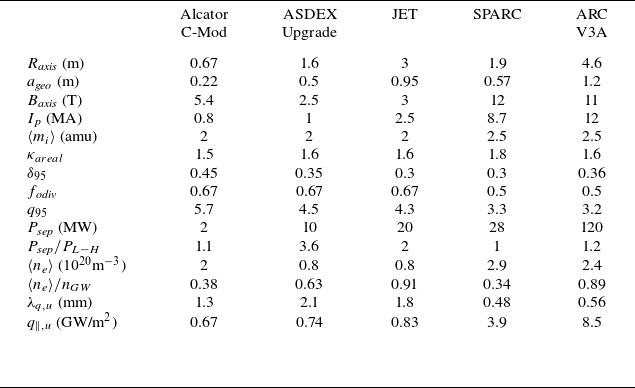


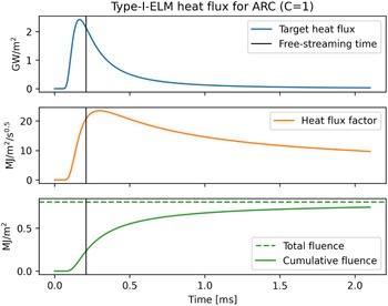


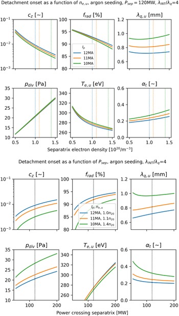


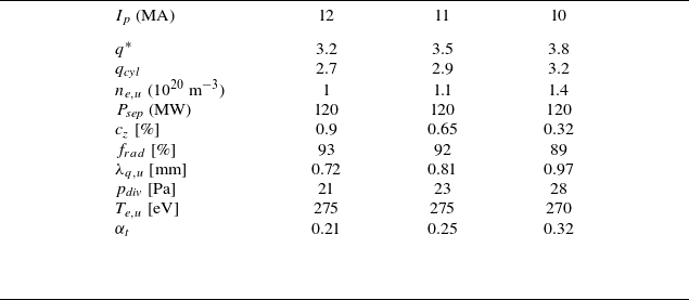


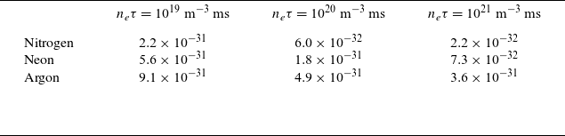


 Open access

