

Introduction
The primary motivation for the work described in the present paper was to create a reliable level wind system for use with the deep ice-sheet coring (DISC) drill. One point to bear in mind with regard to this drill system is that it operates with cable speeds up to 2.5 m s−1. In general, winching speeds were considered to be of primary importance to the drilling operation because most of the time spent at the drill site is spent winching the drill in and out of the borehole. Consider, for example, a drilling depth of 2000 m, a descent speed of 1.0 m s−1 and an ascent speed of 1.0 m s−1. In total, then, some 4000 s (66.6 min) are spent simply moving the drill through the borehole. If the ascent speed is increased to 2.5 m s−1, only 46 min are required, a saving of 20 min per drill run. Cumulatively, over weeks of drilling, this is a sizable increase in ‘product output’, i.e. more ice cores can be drilled per season. Pursuing higher winching speed is therefore important to the overall efficiency of a drilling system. Descent speed is not easily increased as it is limited by the drill’s terminal velocity in fluid (i.e. its ‘freefall’ speed), which in the case of the DISC drill is ∼1 m s−1, depending on borehole diameter.
Traditionally, there are several ways of creating reliable level winding. Lebus, for example, utilizes a passive mechanical feedback system to achieve level winding (Reference LendersLenders, 1961; Reference SeidenatherSeidenather, 2013). Other commercial manufacturers have mechanical feedback systems akin to Lebus’. A second, and perhaps more common, approach is to implement a fixed gear ratio between the rotation of the winch drum and the level wind sheave, causing the level wind sheave to move at a horizontal velocity proportional to the rotational speed of the winch drum. A third approach, akin to the second approach, implements the fixed gear ratio between winch drum and level wind sheave electronically by driving the level wind sheave with a separate motor. This motor’s speed is then carefully matched to the rotational speed of the winch drum by means of a sensing device and closed-loop motor control.
While these approaches have been shown to be successful in many applications, the two latter designs are particularly sensitive to changes in operating conditions (e.g. cable load, temperature, sensor tolerance, computational accuracy and wear of mechanical parts). The DISC drill originally made use of a level wind system which electronically implemented the relation between the rotational speed of the winch drum and the horizontal speed of the level wind sheave. It was found that this approach demanded regular adjustment of the level wind ‘tracking’ with the winch drum in order to make sure that the cable was continually wound correctly onto the drum. Any mismatch between the rotational and horizontal speeds would effect a gradual accumulation of error in the position of the level wind sheave relative to the cable’s entry point onto the winch drum. Ultimately, if not corrected in time, this would lead to the cable skipping turns on the drum or wrapping back onto the previous turn. These consequences lead to concerns regarding cable life, and safety of the system.
The reader may perhaps better appreciate the gravity of these concerns when considering the aforementioned load on the cable. If the cable skips a turn, the operator is alerted by the explosion-like ‘bangs’ that usually accompany the event. This effect is amplified if cable speed is increased. A mis-wrap of this nature was usually followed by a sequence of: stopping the winch, unwinding the faulty turn(s), readjusting the level wind, and possibly a full system reset involving rebooting the level wind control computer. Since an Antarctic drilling season is of limited duration and fairly costly, clearly any malfunction should be avoided if at all possible. With this motivation, it was decided to attempt an altogether different approach to the design of the DISC drill level wind.
Theory of Operation
Although several implementations were created to mature the new concept, this discussion will focus strictly on the first implementation created. The reason for this emphasis is that the first implementation was simple in its design, and therefore best serves the purpose of communicating the salient points of the system without the technical sophistication introduced in later versions. The new design is based on one important observation: the presence of either a Lebus groove or an underlying layer of cable causes cable currently being wound onto the drum to have a natural tendency to wind correctly.
In other words, there exists a range of fleet angle within which the cable will wind correctly. The job of the level wind becomes to maintain a fleet angle of ideally 90°. A ‘small’ deviation from the ideal 90° is permissible so long as the horizontal force due to non-90° fleet angle is less than the force it takes to pull the cable out of the Lebus groove, or valley between cable turns. Figures 1 and 2 illustrate these effects.
Cross-sectional view of a cable drum. Layer 1 is fully wound, and layer 2 is being wound on top of layer 1. The valleys between turns provide guidance for layer 2, causing it to wind correctly.

If misalignment exists between the level wind sheave and the cable’s entry point onto the drum, the fleet angle is different from 90° and an undesirable horizontal force occurs. The horizontal force will tend to pull the cable out of the appropriate valley, and into the next, causing a mis-wrap.

Based on the observation that the cable naturally winds correctly due to the guiding effect of the underlying layer (or Lebus groove), the task of the level wind can now be thought of as simply maintaining a near-90° fleet angle, and the natural guiding will cause the cable to wind correctly. To achieve this, a system was designed where the fleet angle was measured continually and fed back to the motor moving the level wind sheave. This feedback approach allows for continuous adjustment of the level wind speed based on the measured fleet angle. Figure 3 shows the basic idea.
Sketch of a closed-loop feedback system. The fleet angle is kept at ∼90° by means of continuous adjustment through feedback. A sensor measures the fleet angle with the aid of a fork at the end of an arm rotating around a swivel (or pivot); a sensor interface translates the fleet angle into a speed command which, via a motor controller, causes the motor speed to be directly proportional to the fleet angle.
Brush D.C. Motor Experimental Set-Up
The fleet angle is treated as the controlled variable in the system, which attempts to hold it at 90°. If the control system can successfully keep the fleet angle within a range where the cable’s self-guiding can be relied upon, then the cable will wind correctly onto the drum. Experiments revealed that the ‘tolerable range’ was ∼±10°, depending on cable geometry, material, temperature and load. In the interest of establishing early laboratory results, an experimental set-up was constructed based on the sketch shown in Figure 3. For the sake of simplicity, a d.c. motor was chosen for the purpose, driven from a very basic and simple pulse width modulation (PWM)-type controller. Figure 4 shows a simplified schematic of the design.
Simplified schematic of first laboratory design. The fleet angle is sensed with a simple slide potentiometer; the polarity of the sensed signal determines the direction of the motor rotation by means of a comparator and a relay. The speed command signal is simply the rectified sensed signal amplified by an op-amp and fed into the PWM power amplifier driving the motor.

From Figure 4, it can be seen that the fork is used to move the brush of a potentiometer. The potentiometer was a slide-type device, where the slider was attached to the end of the fork-arm as indicated by the dashed line between the fork-arm and potentiometer in Figure 4. In this manner, the output voltage of the potentiometer can be seen as a measurement of fleet angle, where 0 V corresponds to 90°. Negative voltage implied reverse motor rotation, and positive voltage implied forward motor rotation. A comparator was used to detect the polarity of the potentiometer voltage and use that information to set a DPDT (double pole, double throw) relay to either forward or reverse motor voltage. Figure 5 shows the electronics mock-up used for the experiment, and Figure 6 shows the winch with level wind, potentiometer, etc.
Mock-up of controller used to drive d.c.-motor-based experimental set-up. An LED was used to indicate motor direction; a trimmer allowed adjustment of proportional gain. Screw terminals were generally used for power input and output, monitoring, inter-board wiring, etc.

Experimental set-up allowing test of the level wind concept. One winch acts as the source winch with level wind; a second winch simulates the borehole and provides cable tension through braking action.
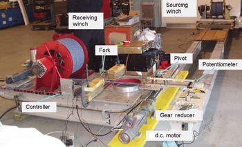
Figure 5 shows how the prototype was constructed using common low-cost techniques. The already simple design made this an attractive approach allowing quick construction and test. Accompanying the controller was the mechanical set-up shown in Figure 6. Two winches from IDDO’s 4-inch drill systems were used. One acted as the sourcing winch with level wind and the other emulated the borehole. The latter was operated in regenerative mode (i.e. the motor was used as a brake) to generate cable tension.
An interesting detail that can be seen in Figure 6 is that no limit switches were implemented to limit the sheave horizontal travel. Instead, wooden blocks were used as hard stops for the cable and fork. Under closed-loop control, physically limiting the cable from getting too close to the drum flanges in this manner had the effect of also limiting the travel of the sheave. This is a direct result of the sheave simply following the cable wherever the cable goes.
The simple set-up described in Figures 4–6 yielded very promising results: the experiment confirmed the theory that the cable has a marked tendency to wind correctly so long as the fleet angle is held within a tolerable range. The exact limits to that range were not established accurately in any quantitative sense as it is affected by several parameters (e.g. cable material, dimensions, tension, etc.). However, qualitatively, it was found that the range was so large that a simple proportional feedback system with only modest loop gain could easily provide the required range.
Since the experimental set-up was simple and unsuited to any real-world application, a more rugged system was designed, destined for WAIS Divide in Antarctica, controlling the 4000 m winch cable used with the DISC drill.
Implementation used at WAIS Divide
The design used in Antarctica with the DISC drill was conceptually identical to that described previously. However, every system member was redesigned to make the system durable and reliable for its application in Antarctica. The existing DISC winch used a level wind which implemented an electronic gear ratio between the winch drum and the level wind. Thus, if the drum moved a certain number of rotations, the level wind lead screw would turn by a proportionally similar amount. Software was in place to determine when the level wind should move in the forward or reverse direction. However, the software was unreliable and prone to errors, further motivating a different approach. The existing system incorporated a lead screw with a separate motor driven by an off-the-shelf controller. Therefore, the existing system was similar to the experimental setup described above, and the experience gained from it was readily applied. Figure 7 shows the design that was used at WAIS Divide. Note the similarity with Figure 4.
Simplified diagram of the design used at WAIS Divide. The slide potentiometer is replaced with an LVDT and ‘AD698 Circuit’ while the primitive PWM motor drive circuit has been replaced with an off-the-shelf three-phase motor drive unit. The d.c. motor is now a 5 HP (3.7 kW) three-phase induction motor. Limit switches are added, stopping the level wind carriage before reaching the drum flanges.

Figure 7 shows how the fleet angle is measured in a manner similar to the simple design described before. A linear variable differential transformer (LVDT) has taken the place of the potentiometer. The more complicated nature of the LVDT requires an ‘interpreting circuit’ to be included in the design. Since LVDTs are common devices, an integrated solution exists, the AD698 IC (integrated circuit) from Analog Devices. This IC includes an oscillator to excite the LVDT’s magnetic circuit and sensing electronics, allowing the creation of an analog output voltage similar to that previously generated using a potentiometer. The advantage of using an LVDT is that it is a very rugged device with only one moving part (the magnetic core) and can be expected to perform well under Antarctic conditions. Figure 8 shows the transfer characteristics of fleet angle vs output voltage.
Fleet angle vs error voltage. The sensor outputs both positive and negative voltage.

As Figure 8 indicates, there is a linear relationship between fleet angle and error voltage. This voltage is then amplified by the operational amplifier with its local feedback network consisting of R1 and R2. The amplified voltage is now rectified to arrive as a positive voltage sent to the motor drive’s frequency reference (the frequency reference can be viewed as an analog speed command input). The motor drive is instructed to go forward or backward depending on the polarity of the error voltage. The two relays, K1 and K2, provide the forward and reverse direction input to the drive. The relays are controlled by the comparator, but can be inhibited by the limit switches on the level wind rail. This ensures that the carriage will not travel beyond the point where the carriage triggers a limit switch. Each limit switch inhibits travel in one direction only.
The design of the fork assembly was altered to allow for an LVDT instead of potentiometer. Additionally, shielding was introduced to reduce the possibility of contaminants entering the rail where the LVDT core met the fork arm. Figure 9 shows an isometric view of the assembly used at WAIS Divide.
Fork assembly using LVDT. The fork arm now has a 90° bend at the pivot, allowing the assembly to fit on top of the sheave assembly.
From Figure 9, it may be seen that the fork arm actuates the core within the LVDT. Additional detail of the design can be found in Figure 10, which is a close-up photograph of the assembly.
Close-up view of the fork assembly. The LVDT core is actuated by a block mounted on a slide rail. In this manner the fleet angle is translated into a linear motion of the LVDT core, generating the error voltage used to set the speed of the level wind motor. This picture was taken during laboratory testing.

The signals to/from the LVDT came from a printed-circuit board (PCB) referred to as the level wind controller. This PCB housed the electronics from the LVDT to the motor drive. In addition, it included a few housekeeping functions (e.g. an enable function, power supplies, etc.). However, its main purpose was to provide the electronic functionality described by Figure 7. Figure 11 shows the PCB designed to translate the signals from the LVDT into speed and direction signals suitable for an off-the-shelf motor drive.
PCB implementation of electronics required to interpret the LVDT and translate the LVDT information into forward, reverse and speed inputs to the motor drive.

The design of the electronics as described in Figure 7 was chosen such that it would easily interface to a range of off-the-shelf motor drives. An interesting point is that many motor drives have similar control inputs across a wide base of manufacturers. This is because there is a common need for these drives to control motors by means of a pendant. The pendant typically has a button for forward motion, reverse motion, a potentiometer for speed and possibly a few other functions. This means that drive manufacturers tend to include control input specifically intended for such a pendant, or similar type control. The PCB designed for the level wind system utilizes this fact by emulating a pendant: it uses relays in place of the pendant buttons and an analog voltage signal in place of the pendant potentiometer. Therefore, although the system at WAIS Divide uses a specific motor drive (Yaskawa F7 type), it is possible to use a range of other drives from other manufacturers as well. The PCB design is not tailored specifically to one motor drive. This detail is likely to increase the system’s applicability to other drill or winching systems.
Conclusion
The feedback approach was based on the thesis that the cable has an inherent tendency to wind correctly. A further aspect of this thesis was that there exists a range of fleet angle within which the cable’s natural tendency to wind correctly can be relied upon.
To verify the thesis, a simple first system was constructed in a laboratory setting. It was indeed found that through application of feedback, a level wind carriage and sheave could be made to follow the cable wherever the cable ‘wanted to go’. Because the cable has a natural tendency to wind correctly, the level wind sheave simply follows the cable to the correct location. It was found that the cable provides adequate self-guidance such that significant fleet angle is required to force the cable away from its natural location. Because the fleet angle is significant, it can be readily sensed and used for feedback control. It was found that a fleet angle of several degrees was tolerable. Thus, simple proportional feedback is adequate to control the level wind.
Though not discussed here, additional laboratory variations were created, ultimately leading to the final design as described in Figure 7. This final design was simply a ruggedized version of the simple early version first described. It was found that the principles studied with the simple prototype translated perfectly to the (much larger) winch system used at WAIS Divide. This suggests that the feedback approach works on fundamental principles and that the technology can therefore be migrated to other winches with different applications.
The final system was used successfully during four seasons, including the 2012/13 replicate coring season, at WAIS Divide.
Acknowledgements
We thank the US National Science Foundation (NSF) Office of Polar Programs for the funding to make this project possible. This work was supported under NSF Cooperative Agreement OPP-0841135.


