


1 Introduction
Laser-driven electron beams have garnered significant attention in diverse fields, including high-brightness X-/gamma-rays[ Reference Senthilkumaran, Bailie, Behm, Warwick, Samarin, Maksimchuk, Nees, Thomas, Sarri, Krushelnick and Hussein 1 – Reference Yan, Fruhling, Golovin, Haden, Luo, Zhang, Zhao, Zhang, Liu, Chen, Chen, Banerjee and Umstadter 4 ], transition radiation (TR)[ Reference Kieffer, Bergamaschi, Bravin, Farabolini, Karataev, Lefevre and Mazzoni 5 ], fast ignition fusion[ Reference Theobald, Solodov, Stoeckl, Anderson, Betti, Boehly, Craxton, Delettrez, Dorrer, Frenje, Glebov, Habara, Tanaka, Knauer, Lauck, Marshall, Marshall, Meyerhofer, Nilson, Patel, Chen, Sangster, Seka, Sinenian, Ma, Beg, Giraldez and Stephens 6 – Reference Robinson, Strozzi, Davies, Gremillet, Honrubia, Johzaki, Kingham, Sherlock and Solodov 8 ] and plasma ultrafast probes[ Reference Zhang, Hua, Wu, Fang, Ma, Zhang, Liu, Peng, He, Huang, Marsh, Mori, Lu and Joshi 9 ]. With the advances in high-intensity laser technology, a table-top laser wakefield accelerator (LWFA) driven by a high-repetition-rate TW/PW-class laser can generate electron beams at the gigaelectronvolt (GeV) scale with quasi-monoenergetic spectra worldwide[ Reference Wang, Li, Liu, Zhang, Qi, Yu, Liu, Fang, Qin, Wang, Xu, Wu, Leng, Li and Xu 10 – Reference Maiolino, Schneider, Oliva, Bianchi, Ferrara, Mannucci, Pedani and Sogorb 13 ]. The charge of such beams is typically tens to hundreds of picocoulombs (pC) due to the relatively low-density gaseous targets. While planar solid targets can produce electron beams with charge of the order of nanocoulombs via resonant absorption[ Reference Estabrook and Kruer 14 , Reference Palastro, Shaw, Follett, Colaïtis, Turnbull, Maximov, Goncharov and Froula 15 ], vacuum heating[ Reference Chen, Zhang, Dong, Teng, Liang, Zhao and Wei 16 ], J×B heating[ Reference Kruer and Estabrook 17 ], and so on, the electron beam’s collimation and uniformity degrade due to the plasma instabilities when passing through the plasma bulk[ Reference Storm, Solodov, Myatt, Meyerhofer, Stoeckl, Mileham, Betti, Nilson, Sangster, Theobald and Guo 18 , Reference MacLellan, Carroll, Gray, Booth, Burza, Desjarlais, Du, Gonzalez-Izquierdo, Neely, Powell, Robinson, Rusby, Scott, Yuan, Wahlstrom and McKenna 19 ], adversely affecting long-distance particle transport and focusing.
Interactions between intense lasers and micro/nano structures offer a novel scheme for generating high-quality electron beams, utilizing targets such as microwires[ Reference Jiang, Ji, Audesirk, George, Snyder, Krygier, Poole, Willis, Daskalova, Chowdhury, Lewis, Schumacher, Pukhov, Freeman and Akli 20 ], microchannels[ Reference Snyder, Ji, George, Willis, Cochran, Daskalova, Handler, Rubin, Poole, Nasir, Zingale, Chowdhury, Shen and Schumacher 21 , Reference Yang, Li, Wu, Zhu, Zhang, Zhang, Yu, Lu, Zhou, Shan, Cao, Zhao, Zhou and Gu 22 ] and foam[ Reference Bin, Yeung, Gong, Wang, Kreuzer, Zhou, Streeter, Foster, Cousens, Dromey, Meyer-ter-Vehn, Zepf and Schreiber 23 , Reference Rosmej, Gyrdymov, Andreev, Tavana, Popov, Borisenko, Gromov, Gus’kov, Yakhin, Vegunova, Bukharskii, Korneev, Cikhardt, Zähter, Busch, Jacoby, Pimenov, Spielmann and Pukhov 24 ]. These structures enhance the effective laser–plasma interaction area, leading to improved laser energy absorption. Electrons are accelerated primarily by the direct laser acceleration (DLA) mechanism[ Reference Pukhov, Sheng and Meyer-ter-Vehn 25 , Reference Mangles, Walton, Tzoufras, Najmudin, Clarke, Dangor, Evans, Fritzler, Gopal, Hernandez-Gomez, Mori, Rozmus, Tatarakis, Thomas, Tsung, Wei and Krushelnick 26 ] rather than ponderomotive acceleration. Propagating in the structure, the laser electric field pulls electrons out of the structure, which gain relativistic velocities in the forward direction by the laser magnetic field. This enables the production of electron beams with both high charge and considerable energy. Such highly directional energetic DLA electrons serve as robust drivers for multiple secondary particle sources and applications. They are particularly used for enhancing proton acceleration[ Reference Bailly-Grandvaux, Kawahito, McGuffey, Strehlow, Edghill, Wei, Alexander, Haid, Brabetz, Bagnoud, Hollinger, Capeluto, Rocca and Beg 27 – Reference Khaghani, Lobet, Borm, Burr, Gartner, Gremillet, Movsesyan, Rosmej, Toimil-Molares, Wagner and Neumayer 29 ], generating high-brightness X-ray and gamma-ray sources[ Reference Yu, Lu, Takahashi, Hu, Gong, Ma, Huang, Chen and Yan 30 – Reference Wang, Ribeyre, Gong, Jansen, d’Humières, Stutman, Toncian and Arefiev 33 ], producing dense positrons[ Reference Jiang, Link, Canning, Fooks, Kempler, Kerr, Kim, Krieger, Lewis, Wallace, Williams, Yalamanchili and Chen 34 ], enabling intense THz radiation[ Reference Yi and Fulop 35 – Reference Mondal, Wei, Ding, Hafez, Fareed, Laramee, Ropagnol, Zhang, Sun, Sheng, Zhang and Ozaki 37 ] and creating strong transient magnetic fields[ Reference Murakami, Honrubia, Weichman, Arefiev and Bulanov 38 ].
Among the structures, microchannels can confine and guide the laser propagation beyond the Rayleigh length. Such prolonged optical guidance further facilitates the collimation and controllability of DLA electrons. Theoretical studies indicate that microchannels can effectively guide the energetic electrons[ Reference Xiao, Huang, Ju, Li, Yang, Yang, Wu, Zhang, Qiao, Ruan, Zhou and He 39 ] through the self-generated plasma fields. When periodic structural arrays are employed as plasma targets, the resulting electron sources usually exhibit distinct spatial distributions correlated to the target geometry, providing a unique approach to manipulate source structures at the micro-scale. These structural beam profiles, often exhibiting a high-order-like mode, are influenced by both the laser focal spots and the spatial arrangement of the structures. To preserve the source profile in the far-field, the generated beam should also be well-collimated such that spatial modulations are not smeared by beam divergence. This has led to difficulties in source-level beam control in laser–plasma systems. Current experimental studies on microstructured targets primarily focus on enhancing particle generation[ Reference Snyder, Ji, George, Willis, Cochran, Daskalova, Handler, Rubin, Poole, Nasir, Zingale, Chowdhury, Shen and Schumacher 21 , Reference Yang, Li, Wu, Zhu, Zhang, Zhang, Yu, Lu, Zhou, Shan, Cao, Zhao, Zhou and Gu 22 , Reference Bailly-Grandvaux, Kawahito, McGuffey, Strehlow, Edghill, Wei, Alexander, Haid, Brabetz, Bagnoud, Hollinger, Capeluto, Rocca and Beg 27 , Reference Bruhaug, Rinderknecht, Weichman, VanDusen-Gross, Palastro, Wei, Regan, E, Garriga, Zhang, Collins and Rygg 36 ], while research on their beam guiding and modulation capabilities is still rare.
In this work, we observed the guiding and shaping effect of the microchannel on an electron beam accelerated via DLA with a 400-TW femtosecond laser. It is found that the electron beam profile is closely related to the number of channels covered by the laser spot. If the laser energy mainly injects into one channel, a well-collimated Gaussian-distribution beam is generated. The recorded profiles are preserved due to the guiding of the channels. We also give the angular distribution, charge and energy spectrum of the microchannel electron beam. Furthermore, we successfully employ the channel electrons to generate a novel annular X-ray source with very low emittance. This channel-based radiation source enables a compact scheme for the two-photon collision process, with the collision rate depending on both the collision area size and photon number[ Reference Yu, Lu, Takahashi, Hu, Gong, Ma, Huang, Chen and Yan 30 , Reference Wang, Ribeyre, Gong, Jansen, d’Humières, Stutman, Toncian and Arefiev 33 ]. Three-dimensional (3D) particle-in-cell (PIC) simulations were performed to study in detail the process of electron guidance and acceleration, and we observe that under the combined influence of the background plasma field and laser field, electrons undergo helical motion within the channel, eventually achieving isotropic collimation after a sub-millimeter propagation distance.
2 Experiments
The experiments were carried out in a Ti:sapphire laser system with central wavelength λ = 800 nm and duration of 36 fs (full width at half maximum, FWHM), delivering 15 ± 2 J on-target energy. About 40% of the laser energy is enclosed in a focal spot of 12 μm in diameter (FWHM), yielding a peak intensity of (1.4 ± 0.2) × 1020 W/cm2. A schematic of the experimental setup is shown in Figure 1(a). The p-polarized laser pulse is focused by an f/4 off-axis parabolic mirror onto the target. Figure 1(c) shows a scanning electron microscopy (SEM) image of a microchannel array target. The channel length, wall thickness and diameter of the microchannel target are 500, 2 and 12 μm, respectively. The drive laser impinges on the front surface of the target at an incident angle of 15.5°, which is the same as the bias angle of the channels. This setup ensures the laser pulse propagates along the channel axis, avoiding light back-reflecting to the laser chain. The angular distribution of the electron beam is measured by a stack of image plates (IPs, Fujifilm BAS-SR 2040, 5 cm × 5 cm) locating at L 1 = 4.3 cm along the laser direction. Iron filters with different thicknesses are added in front of each IP to attenuate electron energy. Following that, an electron spectrometer (ES) equipped with a BAS-SR IP is placed at L 2 = 25 cm. The IP stack can be removed when measuring the spectrum with the ES. Each IP is scanned to be gray data and then this is transformed into a photo stimulated luminescence (PSL) value according to previous calibration[ Reference Williams, Maddox, Chen, Kojima and Millecchia 40 ].
(a) Schematic of the experimental setup for electron measurement. The laser is incident along the channel axis direction. Electron beams are detected with the IP stack and electron spectrometer. The IP stack in the dashed box is movable. (b) Schematic of the experimental setup for X-ray measurement. (c) SEM image of the microchannel array.

Figure 1(b) illustrates the experimental setup for X-ray distribution measurement. A V-shape, wide-angle dipole magnet with a peak field strength of 1.2 T is positioned 8 cm downstream from the target to deflect charged particles, predominantly electrons and low-energy ions. A 20-μm-thick aluminum foil is mounted at the magnetic field entrance to block the laser. The IP is placed at L 3 = 18.5 cm to measure the X-ray profile, preceded by a 5-mm-thick copper filter for attenuating low-energy radiation. The IP detector is enclosed in a one-end-open lead box.
2.1 Controllable channel electron source
The laser spot might cover a single channel or multiple channels in the experiment. Figures 2(a)–2(e) and 2(f)–2(j) exhibit the typical electron distribution when laser energy mainly injects into one channel and two channels, respectively. For the former, it can be seen that the electron beam shows symmetrical distributions at different energies, close to the electron beams in radio frequency (RF) accelerators. The electron charge reaches approximately 1.5 ± 0.3 nC for energy of more than 10 MeV, which is significantly larger than the 2-μm Al foil case (~0.7 ± 0.2 nC). The uncertainty is dominated by the response of the IP to electrons. In the latter case, part of the laser pulse is inevitably diffracted or reflected by the 2-μm channel wall, leading to a decline in the electron quality. The electron charge decreases by 30% compared with the one-channel case. The electron distribution exhibits two peaks with almost equivalent intensities, indicating that the laser is injected into two channels with similar separate energies (seen in Figures 2(f)–2(j)). For electron sources with sufficiently large divergence angles, spatial modulation at the interaction point is usually smoothed out in the far-field detectors. Here the distinctive profiles in the IPs demonstrate that the electrons are well-guided by the channel such that these features persist even after long propagation to the detectors.
Electron distribution when the laser energy mainly injects into one microchannel (a)–(e) and two microchannels (f)–(j). The colorbar represents the logarithm of the gray value. The black lines in (a) and (f) are the linear intensity distribution along z = 0 and z = 2y – 0.81, respectively.

For the one-channel case, one-dimensional distribution of electrons along the horizontal direction at z = 0 is presented in Figure 3(a). The profiles of electron beams for different energies are very close to the Gaussian fit. Figure 3(b) plots the measured divergence angle as a function of electron energy. The divergence angle decreases sharply from 24° to 14° as the electron energy increases from 5 to 10 MeV, and then remains constant at approximately 14° in the 10–50 MeV energy region. This value is far less than the previous measurements of 30° in planar targets[ Reference Green, Ovchinnikov, Evans, Akli, Azechi, Beg, Bellei, Freeman, Habara, Heathcote, Key, King, Lancaster, Lopes, Ma, MacKinnon, Markey, McPhee, Najmudin, Nilson, Onofrei, Stephens, Takeda, Tanaka, Theobald, Tanimoto, Waugh, Van Woerkom, Woolsey, Zepf, Davies and Norreys 41 ]. Given that the electrons are injected from the channel wall, one could assume that the electron source size is comparable to the channel diameter, and thus the estimated beam emittance is as low as 3.9 mm mrad. Such a well-collimated electron beam has good laminarity, which is beneficial to transmission and focusing for secondary applications.
(a) One-dimensional distribution of electrons along the horizontal direction for typical energies. The dashed lines are after Gaussian fitting. (b) Divergence angles (FWHM) as a function of electron energy. (c) Typical electron energy spectra detected by the ES and IP stack. Triangles and circles represent scenarios of one and two-microchannel injection, respectively.

The electron spectra are measured using the ES when the IP stack is moved away, as shown in Figure 3(c). In different shots, there is a fluctuation in electron number and cut-off energy. It is not only related to the fluctuation of the laser parameter, but also largely due to the different energy losses of reflection caused by the channel wall. The average electron slope temperature is 9.1 MeV, significantly higher than the ponderomotive value of about 3.6 MeV according to the scaling law given by T e [MeV] = 0.511× ((1 + I 0 [W/cm2] λ 2 [μm] / 1.37 × 10¹⁸)1/2 – 1)[ Reference Wilks, Kruer, Tabak and Langdon 42 ]. The observation indicates that the super-ponderomotive acceleration via DLA is dominant, consistent with a previous result[ Reference Bin, Yeung, Gong, Wang, Kreuzer, Zhou, Streeter, Foster, Cousens, Dromey, Meyer-ter-Vehn, Zepf and Schreiber 23 ]. This directional electron beam with moderate energies and large population is suitable for optimizing proton acceleration[ Reference Bin, Yeung, Gong, Wang, Kreuzer, Zhou, Streeter, Foster, Cousens, Dromey, Meyer-ter-Vehn, Zepf and Schreiber 23 ], X-/gamma-ray generation[ Reference Yu, Lu, Takahashi, Hu, Gong, Ma, Huang, Chen and Yan 30 ] and positron production[ Reference Jiang, Link, Canning, Fooks, Kempler, Kerr, Kim, Krieger, Lewis, Wallace, Williams, Yalamanchili and Chen 34 ].
2.2 Ring-shaped X-ray source
Figure 4 maps the X-ray emission from electron–wall interactions in the channel target. As shown in Figure 1(b), a large-entrance magnetic spectrometer is employed to deflect charged particles, enabling the measurement of X-ray distribution along the laser propagation direction. An imaging plate is placed at 18.5 cm from the target, aiming to record the signal of the X-ray behind a 5-mm-thick copper filter; the corresponding photon energy is more than 91 keV. This energy significantly exceeds the Kα emission of the channel wall (primarily composed of SiO2). As clearly observed, the spatial distribution of the X-ray closely follows the channel wall structure, ruling out the betatron radiation as the dominant photon generation mechanism. This is because the radiation from electron betatron oscillations typically exhibits a peaked on-axis profile with a significantly weaker edge[ Reference Rousse, Phuoc, Shah, Pukhov, Lefebvre, Malka, Kiselev, Burgy, Rousseau, Umstadter and Hulin 43 – Reference Zhang, Deng, Jiang, Wang, Wei, Ge, Chu, Chen, Wang, Yan, Feng, Jiang, Hu, Tan, Zeng, Guo, Yang, Qian, Zhu, Zhang, Xu, Leng, Zhou, Li, Wang and Li 45 ]. Here, we conclude that the detected X-ray mainly originates from bremsstrahlung radiation as DLA electrons bombard the wall material. It is further corroborated by the PIC simulation results presented in Figure 4(b), where the bremsstrahlung model[ Reference Wu, He, Yu and Fritzsche 46 , Reference Vyskočil, Klimo and Weber 47 ] is included in the calculation. The profiles and intensity distributions of the experiment and simulation are in essential agreement. This X-ray imaging diagnostic also provides an indirect approach to characterize laser or DLA electron interaction with structures.
(a) Self-luminous imaging of the microchannel in the X-ray band measured in the experiment. All the electrons and ions are deflected by a magnetic spectrometer. A 5-mm copper plate is placed in front of the image plate to shield low-energy radiation and debris from the target. (b) Simulated X-ray distribution with photon energy exceeding 50 keV. (c) Simulated X-ray energy spectrum.

In Figure 4(a), the brightest annular ring in the image demonstrates that the laser energy was predominantly coupled into a single channel. Within the central channel, both the electron energy and population are significantly higher than in adjacent channels. The electron–wall collisions generate substantial X-ray photons, leading to the PSL intensity at the ring wall being about twice that of the central region. The number of photons in the ring region is estimated to be (1.7 ± 0.3) × 108 (energy > 90 keV). The ring exhibits a width of approximately 3.2 mm and an inner diameter of 6.1 mm, where the latter corresponds to the 12-μm inner diameter of the hollow channel core. The inferred source size for the single channel is 16 μm and the divergence angle is approximately 3°, yielding an estimated emittance of 0.8 mm mrad. This source simultaneously features a compact size and low emittance. The X-ray source with ring-shaped energy distribution enables 360° illumination, offering a potential route to a shadowless light field, which holds promising application in many fields, such as atomic physics[ Reference Ishikawa, Higashi, Fuyuno, Morifuji, Kondow and Trampert 48 ], biology[ Reference Chapman, Fromme, Barty, White, Kirian, Aquila, Hunter, Schulz, DePonte, Weierstall, Doak, Maia, Martin, Schlichting, Lomb, Coppola, Shoeman, Epp, Hartmann, Rolles, Rudenko, Foucar, Kimmel, Weidenspointner, Holl, Liang, Barthelmess, Caleman, Boutet, Bogan, Krzywinski, Bostedt, Bajt, Gumprecht, Rudek, Erk, Schmidt, Homke, Reich, Pietschner, Struder, Hauser, Gorke, Ullrich, Herrmann, Schaller, Schopper, Soltau, Kuhnel, Messerschmidt, Bozek, Hau-Riege, Frank, Hampton, Sierra, Starodub, Williams, Hajdu, Timneanu, Seibert, Andreasson, Rocker, Jonsson, Svenda, Stern, Nass, Andritschke, Schroter, Krasniqi, Bott, Schmidt, Wang, Grotjohann, Holton, Barends, Neutze, Marchesini, Fromme, Schorb, Rupp, Adolph, Gorkhover, Andersson, Hirsemann, Potdevin, Graafsma, Nilsson and Spence 49 ] and materials science[ Reference Pandey, Dalal, Dutta, Dixit and Mater 50 ]. The generation of such X-ray sources typically relies on ring-shaped laser spots or specially engineered optical components[ Reference Dicken, Shevchuk, Rogers, Godber and Evans 51 - Reference Zverev, Barannikov, Snigireva and Snigirev 54 ], which now can be produced with novel target geometries.
3 Simulation and discussion
To understand the acceleration process of electrons, 3D PIC simulations are performed using EPOCH code[ Reference Arber, Bennett, Brady, Lawrence-Douglas, Ramsay, Sircombe, Gillies, Evans, Schmitz, Bell and Ridgers 55 ]. The simulation is divided into two parts with different simulation settings, focusing on the guiding effect of channels on electron beams and their energy dynamics evolution characteristics, respectively.
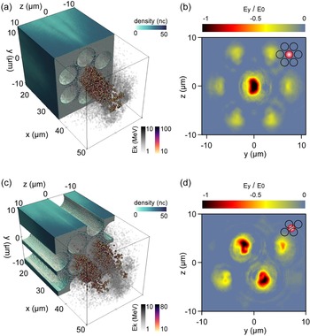
In the first set of simulations, we use smaller laser spot (FWHM = 6 μm), smaller channel diameter (D ch = 6 μm) and shorter channel length (L ch = 35 μm) to reduce computational cost. The 3D simulation box of x × y × z = 50 μm × 22 μm × 20 μm is employed with the resolution of 40 nm × 40 nm × 40 nm. The channel wall is set to fully ionized Si14+ with a thickness of 1 μm, and a 200-nm proton layer is attached to the inner side of the channel wall, with electron densities of 50 n c and 20 n c, respectively. Here, n c = m e ω 2/4πe 2 is the critical density, while ω, m e and e are the laser frequency, electron mass and charge, respectively. The particle per cell values for Si14+, H+ and electrons are 3, 8 and 27, respectively. An 800-nm p-polarized Gaussian laser pulse is incident vertically from the left-hand boundary with a peak intensity of 1.4 × 10²⁰ W/cm2 and a pulse duration of 36 fs. To illustrate the electron beam characteristics for the one- or two-channel injection cases, the laser is focused onto the center of the channel or the channel wall, respectively. These two situations are shown in the insets of Figures 5(b) and 5(d). For the latter configuration, the laser irradiation position is different from the experimental case to enable the plot visualization of two-channel electron beams in Figure 5(c) from the same observation perspective as in Figure 5(a).
Electron beam characteristics from DLA in single-channel (a), (b) and double-channel (c), (d) injection configurations, t = 180 fs, along with laser field distribution at x = 40 μm. The insets in (b) and (d) show the laser energy deposition region within the FWHM spots. Here, E 0 is the initial strength of the laser electric field.

Figures 5(a) and 5(c) present the electron beam profile under different energy allocation schemes in 35-μm-long channels. A clear spatial correlation is observed between the electron bunches and the channel structure, demonstrating the guiding effect of the channel. Although the channel length used in simulation is much shorter than that in realistic scenarios, this configuration suffices to resolve the features of tens of MeV electron beams. In longer plasma channels, high-energy electrons maintain laser-matched spatial profiles throughout co-propagation with the laser field, preserving beam-shape characteristics similar to the laser spot even when experiencing deceleration or dephasing. This further indicates that the size of the high-energy electron source is comparable to the laser-irradiated channel dimensions. For the one-channel injection case in Figure 5(a), the source size of electrons with energies above 10 MeV corresponds to the single-channel diameter, whereas for the two-channel injection case in Figure 5(c), the high-energy electron source size extends to twice the channel diameter. While most laser energy can be coupled into one or two channels, the laser field in the extended area of the Gaussian beam contributes to irradiation of additional channels at lower intensities. These regions exhibit insufficient acceleration fields to reach high electron energies. These electrons correspond to those at the beam periphery.
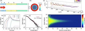
To investigate the dynamical details of long-distance electron guiding in a single channel, we design an independent simulation based on experimental laser and target parameters, that is, a 12-μm laser focus spot and channel diameter, as well as 500-μm channel length and 2-μm wall thickness. The simulation box was changed to x × y × z = 35 μm × 20 μm × 20 μm. The module of moving windows is turned on, with a setting speed of 0.98c. The whole simulation time is 2 ps. As shown in Figure 6(a), the channel is divided into five segments along the x direction. Segments A, B, C, D, E have lengths of 50, 50, 100, 100, 200 μm, respectively. Considering the influence of the pre-pulse, we add a pre-plasma with a scale length of 0.7 μm into the channel. The cross-section distribution of electron density is shown in Figure 6(b). Simulations using this plasma scale length, which is determined through several comparative simulations, successfully reproduce the experimentally measured electron energies.
(a) Segmentation diagram of one microchannel. A, B and C, D represent microchannels with lengths of 50 and 100 μm, respectively. The length of the E part is 200 μm. The inner diameter and wall thickness are 12 and 2 μm, respectively. (b) Density distribution of electrons in a cross-section. The white dashed line marks the critical density position. (c) Maximum energy evolution of electrons from different tube areas. (d) Energy spectrum of electrons running out of the microchannel. (e) Typical electron trajectory across the full 500-μm channel. The color represents electron energy. (f) Divergence angle of electrons with different energy. The angle is according to electron momentum directions in x–y plane.

Figure 6(c) illustrates the maximum energy evolution of the electrons originating from different segments. The electrons located within the first 200 μm of the channel are accelerated to 100–120 MeV in approximately 650 fs; at this time the laser penetration depth is approximately 195 μm, twice the Rayleigh length. Subsequently, due to the electrons dephasing with the acceleration field, high-energy electrons are slowed down to 80 MeV at 1 ps. Within the next 200 μm, the electron energy shows a slow decreasing trend. As the laser propagates in the plasma of the channel, its energy gradually dissipates and the maximum energy of electrons originating from different longitudinal positions also decreases. According to the energy evolution characteristics of electrons from blocks D and E, it can be seen that there is a sudden change in the maximum energy, indicating the overloading effect[ Reference Xu, Shen, Zhang, Wen, Ji, Wang, Yu and Li 56 ] is working. Due to the trapping of a large number of electrons in the laser field, its effect on the electrons is reduced, leading to weak acceleration. This accounts for why the energy of segment D electrons can only reach 13 MeV.
The energy spectrum and divergence angle distribution of the electrons running out of the channel are further analyzed, and the main characteristics of the electron beam were in reasonable agreement with experimental results. Here, the electron slope temperature is 10.4 MeV. Figure 6(f) exhibits the electron divergence at 1.8 ps when they have run out of the channel; it shows that low-energy electrons (0–20 MeV) have relatively large but rapidly decreasing divergence angles. However, the divergence angle of high-energy electrons (20–50 MeV) relatively remains constant at approximately 10°. This phenomenon also indicates that the channel has a more significant guiding effect on high-energy electrons.
During their propagation in the channel, electrons experience not only the Lorentz force from the laser field but also a transverse electric force from the background plasma field; the latter induces betatron oscillations[ Reference Arefiev, Khudik and Schollmeier 57 ]. As shown in Figure 6(e), we track the trajectory of a test electron with out-channel energy of 30 MeV. Under the combined influence of the two forces, the electron follows a helical path with oscillations of varying amplitudes in both the y and z directions. Upon examining the trajectory projection in the x–z plane, the oscillation period is approximately 33 μm within the first 300 μm range. The oscillation amplitude initially reaches 1.5–2 μm but exhibits a slight decay with propagation distance. Over the final 200 μm (t >1.1 ps), the amplitude markedly decreases to 0.3 μm, accompanied by a significant increase in the oscillation period to 100 μm, with nearly no obvious direction deflection. A similar oscillatory characteristic is observed in the projection onto the y–z plane. The simulations demonstrate a clear trend that the electron oscillation amplitude decays while the period elongates with increasing channel length. This evolution is a direct evidence of improved beam collimation throughout the transport, which also suggests that long channels promote more effective electron collimation.
In addition, the main PIC simulation parameters used in Figure 5(a) are also used to calculate the bremsstrahlung photons; their distribution and energy spectrum are presented in Figures 4(b) and 4(c), respectively. The energy spectrum exhibits an exponential decay profile, with the highest photon energies reaching 1–2 MeV. The total number of photons exceeding 50 keV is 2.2 × 10⁷. The simulated channel length is only 35 μm, about one order of magnitude shorter than the actual scale. It is inferred that increasing the channel length or laser intensity would enhance the photon yield.
4 Conclusions
We have experimentally demonstrated the effective guidance and control of laser propagation and electron dynamics using microchannel targets. A relativistic electron beam with good collimation, large charge and elevated temperature is obtained. When laser energy is predominantly coupled into a single channel, the electron beam exhibits enhanced quality, including energy, number and spatial profile. Its good laminarity is ideal for long-distance transport and tight focusing. These capabilities are crucial for the researches in high-energy-density science and laboratory astrophysics. The controllable electron sources will also establish a foundation for many second particle sources, such as our realization of a low-emittance and ring-shaped X-ray source, which exhibits potential for use in photon–photon collision[ Reference Yu, Lu, Takahashi, Hu, Gong, Ma, Huang, Chen and Yan 30 , Reference Wang, Ribeyre, Gong, Jansen, d’Humières, Stutman, Toncian and Arefiev 33 ] and shadowless imaging[ Reference Ji, Zhao, Xing, Liu, Wang, Wan, Liu and Chen 58 ].
Acknowledgements
This work was supported by the National Natural Science Foundation of China (Grant Nos. 12388102 and 12505279), the Strategic Priority Research Program of the Chinese Academy of Sciences (Grant No. XDB0890000), the National Key R&D Program for Young Scientists (Grant No. 2024YFA1612700), the CAS Project for Young Scientists in Basic Research (Grant No. YSBR060), the Shanghai Rising-Star Program (Grant No. 23QA1410600) and the China Postdoctoral Science Foundation (Grant No. 2023M743644).


 Open access