

1 Introduction
The development of high-power ultrafast fiber lasers has been motivated by scientific research and industrial applications in these years[Reference Schibli, Hartl, Yost, Martin, Marcinkevičius, Fermann and Ye1–Reference Pupeza, Holzberger, Eidam, Carstens, Esser, Weitenberg, Rußbüldt, Rauschenberger, Limpert, Udem, Tünnermann, Hänsch, Apolonski, Krausz and Fill3]. These fiber lasers exhibit many outstanding advantages such as high mechanical stability, easy operation, low cost and high average power. Recent advances in both mode-locking method and fiber structure design have led to watt-level average power and sub-100-fs pulse duration directly from fiber laser oscillators, which fulfill the needs in many applications, such as biophotonics and nonlinear optics. The performance of the mode-locked fiber lasers in terms of average power, pulse energy and peak power can be further scaled up by using Yb $^{3+}$
-doped large-mode-area photonic crystal fiber (LMA-PCF)[Reference Baumgartl, Jansen, Stutzki, Jauregui, Ortaç, Limpert and Tünnermann4, Reference Baumgartl, Lecaplain, Hideur, Limpert and Tünnermann5]. However, the air-hole microstructure prevents it from easy connection with standard fiber elements.
$^{3+}$
-doped large-mode-area photonic crystal fiber (LMA-PCF)[Reference Baumgartl, Jansen, Stutzki, Jauregui, Ortaç, Limpert and Tünnermann4, Reference Baumgartl, Lecaplain, Hideur, Limpert and Tünnermann5]. However, the air-hole microstructure prevents it from easy connection with standard fiber elements.
The Yb $^{3+}$
-doped single-mode (SM) double-clad fiber (DCF) turns out to be more flexible than LMA-PCF. By taking advantage of high-power cladding pump, such fibers can also be spliced with any fiber elements, such as combiners and collimators, which makes it possible toward all-fiber structure. In 2001, the Yb
$^{3+}$
-doped single-mode (SM) double-clad fiber (DCF) turns out to be more flexible than LMA-PCF. By taking advantage of high-power cladding pump, such fibers can also be spliced with any fiber elements, such as combiners and collimators, which makes it possible toward all-fiber structure. In 2001, the Yb $^{3+}$
-doped DCF laser was first reported by Hideur et al.
[Reference Hideur, Chartier, Brunel, Louis, Özkul and Sanchez6]. It generated pulses with 430 mW output power, 24 nJ pulse energy and 670 fs pulse duration. Then, Zhao et al. first demonstrated dissipative-soliton (DS) mode-locking mechanism in an all-normal-dispersion cavity of Er
$^{3+}$
-doped DCF laser was first reported by Hideur et al.
[Reference Hideur, Chartier, Brunel, Louis, Özkul and Sanchez6]. It generated pulses with 430 mW output power, 24 nJ pulse energy and 670 fs pulse duration. Then, Zhao et al. first demonstrated dissipative-soliton (DS) mode-locking mechanism in an all-normal-dispersion cavity of Er $^{3+}$
-doped fiber laser[Reference Zhao, Tang and Wu7]. After Chong et al. introduced the DS mode-locking mechanism in Yb
$^{3+}$
-doped fiber laser[Reference Zhao, Tang and Wu7]. After Chong et al. introduced the DS mode-locking mechanism in Yb $^{3+}$
-doped fiber laser, the performance of mode-locked fiber lasers was improved significantly[Reference Chong, Buckley, Renninger and Wise8]. Particularly, Kieu et al. demonstrated 31 nJ pulses with 80 fs dechirped duration from a DS fiber laser with Yb
$^{3+}$
-doped fiber laser, the performance of mode-locked fiber lasers was improved significantly[Reference Chong, Buckley, Renninger and Wise8]. Particularly, Kieu et al. demonstrated 31 nJ pulses with 80 fs dechirped duration from a DS fiber laser with Yb $^{3+}$
-doped SM-DCF as gain fiber[Reference Kieu, Renninger, Chong and Wise9]. Meanwhile, a number of numerical and analytical studies have been conducted to understand the intracavity pulse dynamics in normal-dispersion fiber lasers[Reference Renninger, Chong and Wise10–Reference Renninger, Chong and Wise13]. Comparison between numerical simulation and experimental results[Reference Chong, Renninger and Wise11, Reference Renninger, Chong and Wise14] confirmed that pulse energy can be scaled up by increasing intracavity group-velocity dispersion (GVD). But the large dispersion in cavity makes the dechirped pulse duration be several hundreds of femtosecond because a simple increase of GVD limits output bandwidth. Alternatively, a simple nonlinearity management method can be used. Shorter pulse duration can be achieved by increasing the nonlinear coefficient of passive fibers, while the pulse energy cannot be larger than several nanojoule[Reference Chong, Liu, Nie, Bale, Wabnitz, Renninger, Dantus and Wise15]. Accordingly, neither of them can promise high pulse energy and short dechirped pulse duration simultaneously.
$^{3+}$
-doped SM-DCF as gain fiber[Reference Kieu, Renninger, Chong and Wise9]. Meanwhile, a number of numerical and analytical studies have been conducted to understand the intracavity pulse dynamics in normal-dispersion fiber lasers[Reference Renninger, Chong and Wise10–Reference Renninger, Chong and Wise13]. Comparison between numerical simulation and experimental results[Reference Chong, Renninger and Wise11, Reference Renninger, Chong and Wise14] confirmed that pulse energy can be scaled up by increasing intracavity group-velocity dispersion (GVD). But the large dispersion in cavity makes the dechirped pulse duration be several hundreds of femtosecond because a simple increase of GVD limits output bandwidth. Alternatively, a simple nonlinearity management method can be used. Shorter pulse duration can be achieved by increasing the nonlinear coefficient of passive fibers, while the pulse energy cannot be larger than several nanojoule[Reference Chong, Liu, Nie, Bale, Wabnitz, Renninger, Dantus and Wise15]. Accordingly, neither of them can promise high pulse energy and short dechirped pulse duration simultaneously.
In this paper, we proposed a novel nonlinearity optimization method to address this problem. Nonlinearity optimization is achieved by changing the intracavity distribution of passive fibers in an all-normal-dispersion (ANDi) mode-locked fiber laser. According to a numerical simulation, this nonlinearity optimization effectively increases the output pulse energy, while preserving a large output bandwidth and a short dechirped pulse duration, corresponding to a higher peak power. This method is verified to improve the performance of the DS fiber laser in the following experiment. The laser generates 37 nJ pulses at 82 MHz repetition rate. After compression, the dechirped pulse duration is 66 fs and peak power is as high as 350 kW. To alleviate the pedestal of dechirped pulses, we applied a vector-dispersion compressor (VDC) to independently adjust the third-order dispersion (TOD) of the compressor. As a result of partial compensation of $\unicode[STIX]{x1D6F7}_{\text{NL}}$
accumulated inside the laser cavity, the root mean square (RMS) width of the autocorrelation (AC) trace is shortened from 91 fs to 81 fs.
$\unicode[STIX]{x1D6F7}_{\text{NL}}$
accumulated inside the laser cavity, the root mean square (RMS) width of the autocorrelation (AC) trace is shortened from 91 fs to 81 fs.
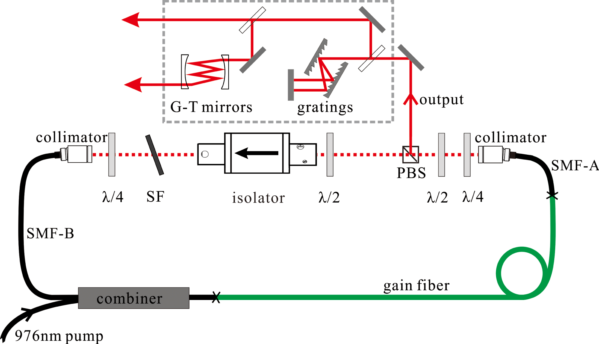
Schematic of the experimental setup. SF, spectral filter; PBS, polarizing beam splitter; gratings and G-T mirrors comprise the VDC, which is shown in the dotted frame. The two output beams are measured to analyze compression result with the grating pair only and VDC.
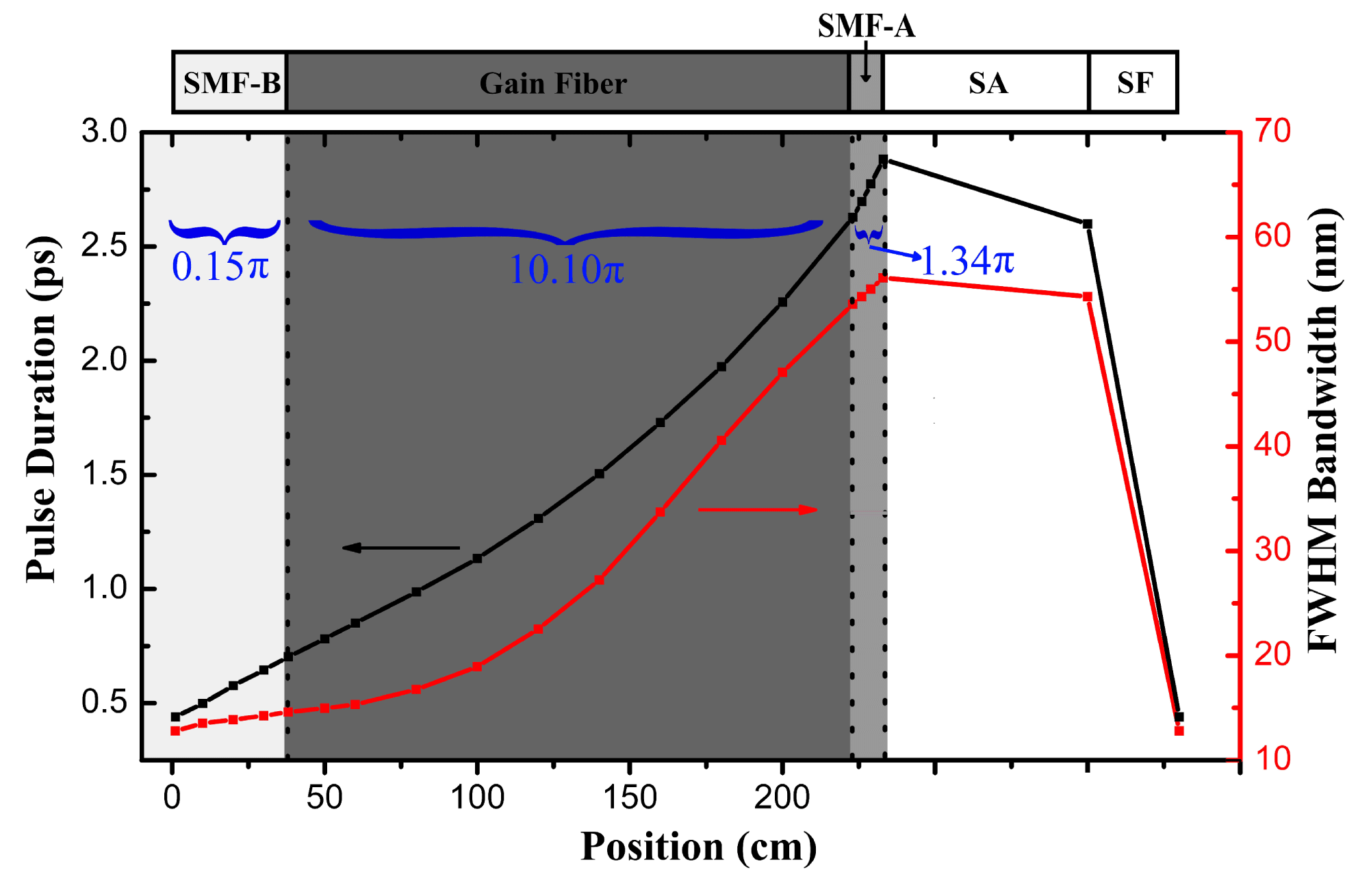
Numerical simulation results of spectral bandwidth and pulse duration evolution in the laser cavity; the pulse enters the SMF-B after the spectral filter (SF).
2 Numerical simulation
Pulse evolution inside a DS fiber laser was investigated by numerically solving the nonlinear Schrödinger equation with gain[Reference Chong, Renninger and Wise11, Reference Ouyang, Chai, Zhao, Hu, Song, Li and Wang12]. We used the standard split-step Fourier method in our simulation with the arrangement of elements in laser cavity as shown in Figure 1. The gain fiber and passive SM fiber have a GVD $\unicode[STIX]{x1D6FD}_{2}=0.023~\text{ps}^{2}/\text{m}$
and a nonlinear coefficient
$\unicode[STIX]{x1D6FD}_{2}=0.023~\text{ps}^{2}/\text{m}$
and a nonlinear coefficient $\unicode[STIX]{x1D6FE}=0.0019\,(\text{W}\cdot \text{m})^{-1}$
. A 1.8-m gain fiber is chosen to absorb most of the pump laser. The intracavity pulse evolution is shown in Figure 2. Both pulse duration and bandwidth increase monotonically in the passive SM fiber before gain fiber (SMF-B, ‘B’ represents ‘before gain fiber’), gain fiber and passive SM fiber after gain fiber (SMF-A, ‘A’ represents ‘after gain fiber’). The saturable absorber (SA) slightly shortens the pulse duration and narrows the optical spectrum. However, the spectral filter (SF) plays a crucial role in reducing the duration and bandwidth by cutting the edges of the spectrum, which balances the pulse evolution in fiber sections over one cavity round trip[Reference Renninger, Chong and Wise13].
$\unicode[STIX]{x1D6FE}=0.0019\,(\text{W}\cdot \text{m})^{-1}$
. A 1.8-m gain fiber is chosen to absorb most of the pump laser. The intracavity pulse evolution is shown in Figure 2. Both pulse duration and bandwidth increase monotonically in the passive SM fiber before gain fiber (SMF-B, ‘B’ represents ‘before gain fiber’), gain fiber and passive SM fiber after gain fiber (SMF-A, ‘A’ represents ‘after gain fiber’). The saturable absorber (SA) slightly shortens the pulse duration and narrows the optical spectrum. However, the spectral filter (SF) plays a crucial role in reducing the duration and bandwidth by cutting the edges of the spectrum, which balances the pulse evolution in fiber sections over one cavity round trip[Reference Renninger, Chong and Wise13].
According to the Ref. [Reference Renninger, Chong and Wise13], the GVD should compensate the $\unicode[STIX]{x1D6F7}_{\text{NL}}$
accumulation in laser cavity to maintain a stable single-pulse operation. For a certain total fiber length, the group-delay dispersion (GDD) of laser cavity is fixed regardless of different passive fiber distribution. Consequently, the maximum
$\unicode[STIX]{x1D6F7}_{\text{NL}}$
accumulation in laser cavity to maintain a stable single-pulse operation. For a certain total fiber length, the group-delay dispersion (GDD) of laser cavity is fixed regardless of different passive fiber distribution. Consequently, the maximum $\unicode[STIX]{x1D6F7}_{\text{NL}}$
accumulation that the GVD can compensate is also decided. Note that
$\unicode[STIX]{x1D6F7}_{\text{NL}}$
accumulation that the GVD can compensate is also decided. Note that $\unicode[STIX]{x1D6F7}_{\text{NL}}$
in each fiber segment is different, which is determined by both fiber length and pulse peak power. Thus, we can scale up the output pulse energy without increasing
$\unicode[STIX]{x1D6F7}_{\text{NL}}$
in each fiber segment is different, which is determined by both fiber length and pulse peak power. Thus, we can scale up the output pulse energy without increasing $\unicode[STIX]{x1D6F7}_{\text{NL}}$
accumulation by changing the distribution of passive fiber segments at a fixed passive fiber length.
$\unicode[STIX]{x1D6F7}_{\text{NL}}$
accumulation by changing the distribution of passive fiber segments at a fixed passive fiber length.
Numerical simulation results. (a) Numerical simulation results of spectral bandwidth (blue circle), dechirped pulse duration (red triangle) and direct output pulse energy (black square). Points A–F represent the different AB-ratios 0.5/0, 0.4/0.1, 0.3/0.2, 0.2/0.3, 0.1/0.4 and 0/0.5, respectively. (b) Autocorrelation trace of the transform-limited pulse of AB-ratio, A (black curve), D (blue curve) and F (red curve). (c) The output maximum and minimum average power of single-pulse operation versus different bandwidths of SF is shown, when AB-ratio is zero. (d) The maximum $\unicode[STIX]{x1D6F7}_{\text{NL}}$
accumulated in the cavity of single-pulse operation versus different bandwidths of spectral filter is shown, when AB-ratio is zero.
$\unicode[STIX]{x1D6F7}_{\text{NL}}$
accumulated in the cavity of single-pulse operation versus different bandwidths of spectral filter is shown, when AB-ratio is zero.
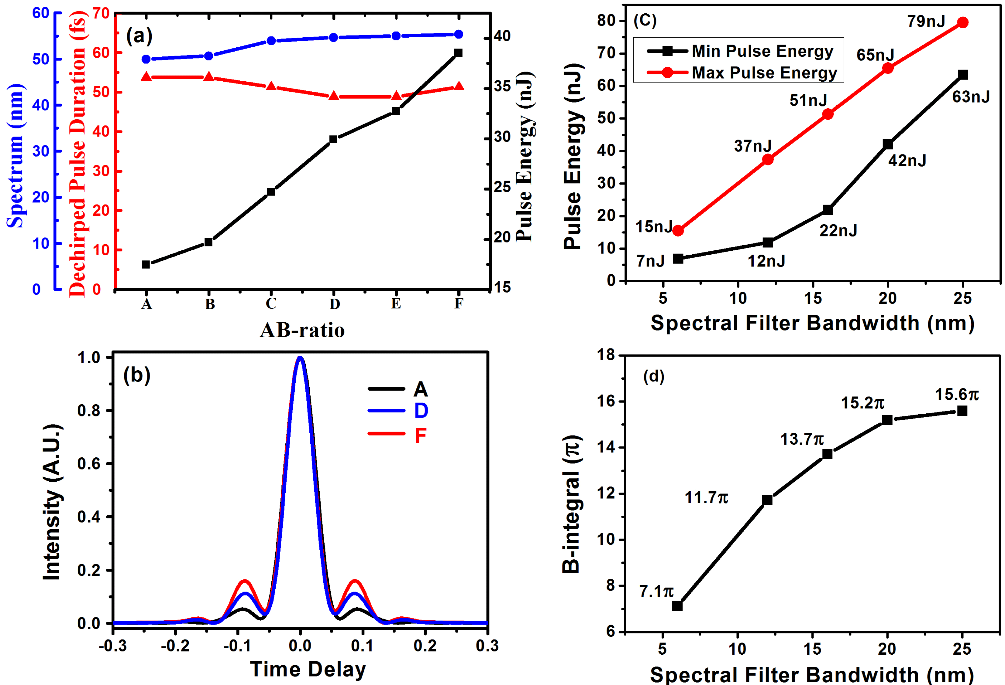
To optimize the intracavity nonlinearity, we first use B-integral to analyze the $\unicode[STIX]{x1D6F7}_{\text{NL}}$
of each fiber segment quantitatively. In the simulation, the B-integral is obtained for SMF-B
$\unicode[STIX]{x1D6F7}_{\text{NL}}$
of each fiber segment quantitatively. In the simulation, the B-integral is obtained for SMF-B $(0.15\unicode[STIX]{x03C0})$
, gain fiber
$(0.15\unicode[STIX]{x03C0})$
, gain fiber $(10.1\unicode[STIX]{x03C0})$
and SMF-A
$(10.1\unicode[STIX]{x03C0})$
and SMF-A $(1.34\unicode[STIX]{x03C0})$
, as shown in Figure 2. Considering the fiber length, the average B-integral parameters are
$(1.34\unicode[STIX]{x03C0})$
, as shown in Figure 2. Considering the fiber length, the average B-integral parameters are $0.39\unicode[STIX]{x03C0}~\text{rad}/\text{m}$
for SMF-B,
$0.39\unicode[STIX]{x03C0}~\text{rad}/\text{m}$
for SMF-B, $5.6\unicode[STIX]{x03C0}~\text{rad}/\text{m}$
for gain fiber and
$5.6\unicode[STIX]{x03C0}~\text{rad}/\text{m}$
for gain fiber and $11.2\unicode[STIX]{x03C0}~\text{rad}/\text{m}$
for SMF-A. It is clear that
$11.2\unicode[STIX]{x03C0}~\text{rad}/\text{m}$
for SMF-A. It is clear that $\unicode[STIX]{x1D6F7}_{\text{NL}}$
accumulation of SMF-A is larger than that of SMF-B. Moreover, the average B-integral parameter of SMF-A is the highest among these three fiber segments. Since the nonlinearity in SMF-A is larger than this parameter in other fiber segments, shorter SMF-A potentially results in less
$\unicode[STIX]{x1D6F7}_{\text{NL}}$
accumulation of SMF-A is larger than that of SMF-B. Moreover, the average B-integral parameter of SMF-A is the highest among these three fiber segments. Since the nonlinearity in SMF-A is larger than this parameter in other fiber segments, shorter SMF-A potentially results in less $\unicode[STIX]{x1D6F7}_{\text{NL}}$
accumulation. Thus, we can scale up output pulse energy by optimizing the intracavity nonlinearity by changing the length ratio of SMF-A to SMF-B (AB-ratio). This is verified in Figure 3. With the fixed total passive fiber length and gain fiber length, the highest output pulse energy increases from 17 nJ to 38 nJ along with the AB-ratio decreasing, until AB-ratio becomes zero. Note that, the total B-integral in the laser cavity is constant at around
$\unicode[STIX]{x1D6F7}_{\text{NL}}$
accumulation. Thus, we can scale up output pulse energy by optimizing the intracavity nonlinearity by changing the length ratio of SMF-A to SMF-B (AB-ratio). This is verified in Figure 3. With the fixed total passive fiber length and gain fiber length, the highest output pulse energy increases from 17 nJ to 38 nJ along with the AB-ratio decreasing, until AB-ratio becomes zero. Note that, the total B-integral in the laser cavity is constant at around $12\unicode[STIX]{x03C0}$
, in spite of pulse energy scaling up. This means that the output spectrum is nearly unchanged, so is the dechirped pulse duration. In this way, we can scale up the output pulse energy and maintain a short dechirped pulse duration, corresponding to boosting peak power. In the cavity, the SF is also vital to the evolution of the pulses. In the simulation, we analyze the impact of SF bandwidth on the pulse energy and
$12\unicode[STIX]{x03C0}$
, in spite of pulse energy scaling up. This means that the output spectrum is nearly unchanged, so is the dechirped pulse duration. In this way, we can scale up the output pulse energy and maintain a short dechirped pulse duration, corresponding to boosting peak power. In the cavity, the SF is also vital to the evolution of the pulses. In the simulation, we analyze the impact of SF bandwidth on the pulse energy and $\unicode[STIX]{x1D6F7}_{\text{NL}}$
accumulation, as shown in Figure 3. The pulse energy and
$\unicode[STIX]{x1D6F7}_{\text{NL}}$
accumulation, as shown in Figure 3. The pulse energy and $\unicode[STIX]{x1D6F7}_{\text{NL}}$
increase with the increase of SF bandwidth because broader bandwidth of SF makes the pulse duration after SF longer. But there is an optimal SF bandwidth for a fixed GVD. The deviation from it would weaken self-amplitude modulation and make the laser difficult to be mode-locked. As a result, we select the 12-nm SF for our simulation and experiment.
$\unicode[STIX]{x1D6F7}_{\text{NL}}$
increase with the increase of SF bandwidth because broader bandwidth of SF makes the pulse duration after SF longer. But there is an optimal SF bandwidth for a fixed GVD. The deviation from it would weaken self-amplitude modulation and make the laser difficult to be mode-locked. As a result, we select the 12-nm SF for our simulation and experiment.
Unfortunately, the pedestal of dechirped pulse becomes more observable as the AB-ratio is reduced, which is shown in Figure 3(b). The reason is that more spectral broadening in gain fiber makes gain narrowing effect more obvious when AB-ratio decreases. As a result, dechirped output pulse degrades. To overcome this drawback, the VDC can be applied to suppress this pedestal[Reference Zhang, Torizuka, Itatani, Kobayashi, Sugaya and Nakagawa16, Reference Xie, Liu, Niu, Song, Li, Hu, Zhang, Shen, Liu and Wang17].
3 Experimental results
According to the numerical simulation result, we zeroed AB-ratio so as to support the highest pulse energy in the experiment[Reference Chi, Liu, Song, Hu, Chai, Shen, Liu and Wang18]. To realize zeroed AB-ratio, we removed the passive fiber after the gain fiber, which was connected directly with the collimator (Thorlabs, Item#: F220APC-1064). The experimental setup is shown in Figure 1. The gain fiber is a 1.8 m Yb $^{3+}$
-doped SM-DCF (LIEKKI-Yb1200-10/125) with
$^{3+}$
-doped SM-DCF (LIEKKI-Yb1200-10/125) with $10~\unicode[STIX]{x03BC}\text{m}$
core diameter and
$10~\unicode[STIX]{x03BC}\text{m}$
core diameter and $125~\unicode[STIX]{x03BC}\text{m}$
inner cladding diameter. The SMF-B (LIEKKI-Passive-10/125DC) is about 50 cm. A laser diode at 976 nm provides enough pump power via a high-power
$125~\unicode[STIX]{x03BC}\text{m}$
inner cladding diameter. The SMF-B (LIEKKI-Passive-10/125DC) is about 50 cm. A laser diode at 976 nm provides enough pump power via a high-power $(1+1)\times 1$
forward-pumping combiner. The efficiency of pump coupling is above 90%. A set of wave plates and a polarization beam splitter implement the nonlinear polarization evolution. To obtain easy-started and stable mode-locking, 12-nm spectral filter with the center wavelength of 1040 nm is used. A free-space isolator is employed to guarantee a unidirectional propagation. The maximum transmittance is ensured by adjusting the half-wave plate before the isolator. To verify the single-pulse operation, output pulses are monitored by a commercial autocorrelator (APE Pulse-Check) with 50 ps delay range, an oscilloscope (20 GHz bandwidth module, HP 83485A) with a fast photodiode (35 ps rising time) and a 400-MHz analog oscilloscope with another photodiode (200 ps rising time).
$(1+1)\times 1$
forward-pumping combiner. The efficiency of pump coupling is above 90%. A set of wave plates and a polarization beam splitter implement the nonlinear polarization evolution. To obtain easy-started and stable mode-locking, 12-nm spectral filter with the center wavelength of 1040 nm is used. A free-space isolator is employed to guarantee a unidirectional propagation. The maximum transmittance is ensured by adjusting the half-wave plate before the isolator. To verify the single-pulse operation, output pulses are monitored by a commercial autocorrelator (APE Pulse-Check) with 50 ps delay range, an oscilloscope (20 GHz bandwidth module, HP 83485A) with a fast photodiode (35 ps rising time) and a 400-MHz analog oscilloscope with another photodiode (200 ps rising time).
Experimental results. (a) Output average power (black square) and dechirped pulse duration (red triangle) versus pump power. (b) Pulse train, 50 ns/div, detected by photodiode (200 ps rising time) and analog oscilloscope (400 MHz bandwidth). Inset: two consecutive pulses, 2 ns/div, detected by photodiode (35 ps rising time) and oscilloscope (20 GHz bandwidth). (c) Autocorrelation trace of direct output pulse in a long scan range. Inset: autocorrelation of pulse dechirped by gratings (black solid curve) and transform-limited pulse. (d) Output spectrum when AB-ratio is 0 (black solid curve) and 0.32 (red dotted curve).

By adjusting the wave plates, the stable single-pulse operation is achieved over a pump power range from 4.4 W to 9.2 W, as shown in Figure 4(a). When the pump power is 9.2 W, the output average power is 3 W at 82 MHz repetition rate, corresponding to 37 nJ pulse energy. The direct output pulse duration is 2.4 ps. A single-pulse operation is obtained, as verified by oscilloscopes and autocorrelator, as shown in Figures 4(b) and 4(c), respectively. After a grating pair (600 lines/mm), the pulses can be compressed to 66 fs. The AC trace and spectrum after pulse dechirping are shown in Figures 4(c) and 4(d), respectively. Further increasing the pump power will drive the laser into multi-pulse operation.
For comparison, we then changed the AB-ratio to 0.32, with the identical total passive fiber length, gain fiber length and other cavity parameters. These identical parameters promise the same total GVD and repetition rate. The fiber length of SMF-B is 0.38 m, and the SMF-A is 0.12 m. In this situation, the highest pulse energy of single-pulse operation is only 18 nJ. The pulse can be compressed to 88 fs. Thus, this comparison proves that the output pulse energy can be scaled up by decreasing AB-ratio.
As pulse energy rises up, the $\unicode[STIX]{x1D6F7}_{\text{NL}}$
accumulation is enhanced. Correspondingly, the pedestals of dechirped pulses become more obvious. To alleviate pulse distortion simply and efficiently, the TOD of the compressor is proposed to partially compensate
$\unicode[STIX]{x1D6F7}_{\text{NL}}$
accumulation is enhanced. Correspondingly, the pedestals of dechirped pulses become more obvious. To alleviate pulse distortion simply and efficiently, the TOD of the compressor is proposed to partially compensate $\unicode[STIX]{x1D6F7}_{\text{NL}}$
[Reference Shah, Liu, Hartl, Imeshev, Cho and Fermann19, Reference Zhou, Kuznetsova, Chong and Wise20]. However, the common grating pair provides the fixed GDD-to-TOD ratio. It is difficult to adjust the grating pair to compensate the
$\unicode[STIX]{x1D6F7}_{\text{NL}}$
[Reference Shah, Liu, Hartl, Imeshev, Cho and Fermann19, Reference Zhou, Kuznetsova, Chong and Wise20]. However, the common grating pair provides the fixed GDD-to-TOD ratio. It is difficult to adjust the grating pair to compensate the $\unicode[STIX]{x1D6F7}_{\text{NL}}$
independently, which always leads to large pedestal, as shown in Figure 4(c). To overcome this drawback, we applied the vector-dispersion compressor[Reference Zhang, Torizuka, Itatani, Kobayashi, Sugaya and Nakagawa16, Reference Xie, Liu, Niu, Song, Li, Hu, Zhang, Shen, Liu and Wang17], which consists of gratings and specially designed multipass cell-based TOD Gires Tournois interferometer mirrors (GTI mirrors) as shown in the dotted frame of Figure 1. By optimizing the bounce number on GTI mirrors and the separation between gratings, the VDC provides an adjustable dispersion vector (i.e., the ratio of TOD to GDD). The
$\unicode[STIX]{x1D6F7}_{\text{NL}}$
independently, which always leads to large pedestal, as shown in Figure 4(c). To overcome this drawback, we applied the vector-dispersion compressor[Reference Zhang, Torizuka, Itatani, Kobayashi, Sugaya and Nakagawa16, Reference Xie, Liu, Niu, Song, Li, Hu, Zhang, Shen, Liu and Wang17], which consists of gratings and specially designed multipass cell-based TOD Gires Tournois interferometer mirrors (GTI mirrors) as shown in the dotted frame of Figure 1. By optimizing the bounce number on GTI mirrors and the separation between gratings, the VDC provides an adjustable dispersion vector (i.e., the ratio of TOD to GDD). The $\unicode[STIX]{x1D6F7}_{\text{NL}}$
can be compensated accurately to suppress the wing structure. In the experiment, we optimize the VDC for pulse compensation at a pump power of 9.2 W and find the observable suppression of pedestals, as shown in Figure 5. As a result, RMS width of the AC trace is decreased from 91 fs to 81 fs. The pulse energy is mostly confined in the main peak to produce
$\unicode[STIX]{x1D6F7}_{\text{NL}}$
can be compensated accurately to suppress the wing structure. In the experiment, we optimize the VDC for pulse compensation at a pump power of 9.2 W and find the observable suppression of pedestals, as shown in Figure 5. As a result, RMS width of the AC trace is decreased from 91 fs to 81 fs. The pulse energy is mostly confined in the main peak to produce ${\sim}350~\text{kW}$
peak power with
${\sim}350~\text{kW}$
peak power with ${\sim}62\%$
efficiency of the VDC (64% efficiency for double pass in 600 lines/mm grating pair, 96.8% total efficiency for 32 bounces on the G-T mirror with 99.9% reflectance), and the polarization of the beam is still maintained.
${\sim}62\%$
efficiency of the VDC (64% efficiency for double pass in 600 lines/mm grating pair, 96.8% total efficiency for 32 bounces on the G-T mirror with 99.9% reflectance), and the polarization of the beam is still maintained.
Autocorrelation trace of pulse dechirped by different bounce number of VDC. Inset: details on root of dechirped pulses.

4 Conclusion
In conclusion, we have proposed and demonstrated a solution to optimize the nonlinearity of DS mode-locked fiber laser in ANDi regime to scale up the pulse energy with sub-100-fs dechirped pulse duration. The pulse with 37-nJ energy is obtained from a DS cladding pumped Yb-fiber laser by using this method. After compression, the pulse duration is 66 fs and peak power is 350 kW. With the help of vector-dispersion compressor, the pedestal of the dechirped pulse is effectively suppressed. In the future, a systematical optimization on the total fiber length and bandwidth and shape of SF will be a promising route to further improve the performance of mode-locked fiber lasers.
Acknowledgements
This work was partially supported by the National Natural Science Foundation of China (Nos. U1730115, 61535009, and 11527808) and the Open Fund of the State Key Laboratory of High Field Laser Physics (Shanghai Institute of Optics and Fine Mechanics).


 Open access