

1 Introduction
Conventionally, nonlinear media are employed to transform the fundamental frequency of the input laser to those of high harmonics to obtain extreme ultraviolet and even X-ray beams using table-top lasers[Reference Kohler, Pfeifer, Hatsagortsyan, Keitel, Berman, Arimondo and Lin1, Reference Jaeglé, Samson and Ederer2]. High harmonic generation (HHG), as an ideal tool, can be applied in probing electronic dynamics on the atomic or molecular scale, microscale imaging, etc. Gases or metals are utilized to generate high-order harmonics for lasers with intensities around 1014–16 W/cm2[Reference Hernandez-Garcia, Picon, Roman and Plaja3–Reference Winterfeld, Spielmann and Gerber7], and a plasma target is ideal for lasers with much higher intensities, i.e., approximately or over 1018 W/cm2[Reference Nomura, Horlein, Tzallas, Dromey, Rykovanov, Major, Osterhoff, Karsch, Veisz, Zepf, Charalambidis, Krausz and Tsakiris8–Reference Pan, Yang, Guo, Li, Li, Zheng, Jiang, Zhang and He15]. In general, all harmonics couple with the input laser(s), and they are not separated outside the interaction domain[Reference Shen and Meyer-ter-Vehn16-Reference Zhang, Shen, Shi, Zhang, Ji, Wang, Xu and Tajima20]; consequently, additional spectrometers are usually utilized to separate a specific-order harmonic for application[Reference Suzuki and Heinz21-Reference Bertrand, Worner, Bandulet, Bisson, Spanner, Kieffer, Villeneuve and Corkum23]. Angular separation of high harmonics from solid plasma targets has been achieved experimentally in a single-beam scheme by using grating targets[Reference Cerchez, Giesecke, Peth, Toncian, Albertazzi, Fuchs, Willi and Toncian24]. Enhancement of harmonics in the grating scheme via surface plasmon excitation has also been demonstrated[Reference Cantono, Fedeli, Sgattoni, Denoeud, Chopineau, Reau, Ceccotti and Macchi25]. On the other hand, angularly isolated high harmonics from a gas jet were first reportedly generated by two overlapping 1014 W/cm2 non-collinear laser beams[Reference Hickstein, Dollar, Grychtol, Ellis, Knut, Hernandez-Garcia, Zusin, Gentry, Shaw, Fan, Dorney, Becker, Jaron-Becker, Kapteyn, Murnane and Durfee22]. This non-collinear HHG geometry presents numerous advantages[Reference Hickstein, Dollar, Grychtol, Ellis, Knut, Hernandez-Garcia, Zusin, Gentry, Shaw, Fan, Dorney, Becker, Jaron-Becker, Kapteyn, Murnane and Durfee22, Reference Kim, Zhang, Shiner, Kirkwood, Frumker, Gariepy, Naumov, Villeneuve and Corkum26-Reference Kong, Zhang, Bouchard, Li, Brown, Ko, Hammond, Arissian, Boyd, Karimi and Corkum29], including the separation of the harmonics from the pump beams, angular separation of different order harmonics, generation of high-energy photons, and production of isolated attosecond bursts. Evidently, this HHG process meets the phase-matching requirement, which stipulates that the output momentum of an nth-order harmonic photon (k n) is only related to the momentum of the input photons (k 1 and k 2) by the momentum conservation principle, k n = n 1k 1 + n 2k 2, where n 1 and n 2 are the numbers of photons absorbed from each of the input beams, and n = n 1 + n 2[Reference Hickstein, Dollar, Grychtol, Ellis, Knut, Hernandez-Garcia, Zusin, Gentry, Shaw, Fan, Dorney, Becker, Jaron-Becker, Kapteyn, Murnane and Durfee22, Reference Bertrand, Worner, Bandulet, Bisson, Spanner, Kieffer, Villeneuve and Corkum23, Reference Ellis, Dorney, Durfee, Hernandez-Garcia, Dollar, Mancuso, Fan, Zusin, Gentry, Grychtol, Kapteyn, Murnane and Hickstein30]. As far as we know, all this interesting research is based on the gas ionization process, where the laser intensity is generally below 1016 W/cm2, and the crossing angle is small enough to ensure adequate interaction.
In this study, based on a different HHG mechanism, we propose an approach for generating intense isolated harmonics through the interaction between relativistic lasers and a plasma target, but with a quite different phase-matching selection rule. In our approach, two relativistic laser pulses impinge on a solid thin foil at an angle. The generated intense harmonics are naturally separated from each other and from the input beams at considerably large angles, which can be predicted. The proposed approach offers several exclusive benefits. First and most importantly, both our theoretical analysis and three-dimensional particle-in-cell (3D PIC) simulations prove that the nth harmonic carrying the information of both input lasers is converted by its adjacent (n – 1)th harmonic which has the smallest crossing angle with the nth harmonic owing to the highest occurrence possibility and one fundamental input beam, rather than directly by the two input beams in the gas HHG case. That is, considering phase matching, the output momentum (emission direction) of an nth-order harmonic photon depends on the momentum of the (n – 1)th-order harmonic photon and that of one input laser photon, according to the momentum conservation, k n = k n–1 + k 1(2), for the input beams with the same wavelength. Second, plasma, as a nonlinear medium, can endure lasers nearly without the intensity limitation. Therefore, the intensity of isolated harmonics can be in the relativistic region[Reference Teubner and Gibbon31, Reference Gao, Li, Liu, Chen, Chen, Ge, Yuan, Chen, Sheng and Zhang32]. Finally, because the crossing angle between the input lasers can be sufficiently large, the individual harmonic can be emitted at an angle nearly two orders of magnitude higher than that (usually in the milliradian level) in gas HHG. This point is very important for the measurement and application of this method in experiments. It should be noted that a large number of papers on the selection rule for the plasma HHG in terms of the oscillating mirror model, first proposed by Bulanov et al.[Reference Bulanov, Naumova and Pegoraro9] and then studied extensively by Lichters et al.[Reference Lichters, Meyer-ter-Vehn and Pukhov10], have been published. All of them are about a single incident laser or collinear incident lasers, and all of harmonics are coupled spatially. The problems such as proper phase matching do not exist. However, in our case, the harmonic emission is determined by the phase-matching relation and hence isolated angularly.
2 Theoretical analysis
The proposed scheme is shown in Figure 1. Two circularly polarized (CP) laser pulses a 1 and a 2 impinge on a solid thin foil symmetrically at a large crossing angle 2θ. For simplification, two identical input pulses with the same frequency (ω) are considered, and the angle θ = π/4 is the incident angle of each laser pulse. The electrons in the target experience the overlapped fields in the thin foil and oscillate. The harmonics radiated from the oscillating electrons are isolated angularly and propagate in the reflected side and also in the transmitted side if the target is sufficiently thin. The total normalized laser amplitude acting on the target is a = a 1+a 2 ( $a= eA/{m}_e{c}^2$, where A is the vector potential, $c$ is the speed of light in vacuum, ${m}_e$ is the electron mass, and $e$ is the electron charge), where a 1 and a 2 are the driving laser beams used as
 $$\begin{align}{a}_1&={a}_0[\sin (\omega t- kx\cos \theta - ky\sin \theta )\notag\\{}&\times (\overset{\frown }{y}\cos \theta -\overset{\frown }{x}\sin \theta )+\cos (\omega t- kx\cos \theta - ky\sin \theta )\overset{\frown }{z}],\notag\\{}{a}_2&={a}_0[\sin (\omega t- kx\cos \theta + ky\sin \theta )\notag\\{}&\times (\overset{\frown }{y}\cos \theta +\overset{\frown }{x}\sin \theta )\pm \cos (\omega t- kx\cos \theta + ky\sin \theta )\overset{\frown }{z}],\end{align}$$
respectively, for the cases of counter-rotation and same-rotation CP beams, denoted by “–” and “+” in the expression of a 2, a 0 is the peak amplitude, and k is the wavenumber. The transverse components of the laser amplitude acting on the target (with x indicating the longitudinal direction) can be written as
 $$\begin{align}{a}_{\mathrm{CR}\perp}&\sim \sin (\omega t- kx\cos \theta )\notag\\{}&\times [\cos \theta \cos ( ky\sin \theta )\overset{\frown }{y}+\sin ( ky\sin \theta )\overset{\frown }{z}],\notag\\{}{a}_{\mathrm{SR}\perp}&\sim \cos ( ky\sin \theta )\notag\\{} &\times [\cos \theta \sin (\omega t- kx\cos \theta )\overset{\frown }{y}+\cos (\omega t- kx\cos \theta )\overset{\frown }{z}],\end{align}$$
for the counter-rotation and same-rotation cases, respectively. This expression for counter-rotation CP pulses shows a linearly polarized laser pulse. According to the γ-spikes theory of the relativistic oscillating mirror model[Reference Baeva, Gordienko and Pukhov11, Reference Chen and Pukhov33], harmonics can be efficiently generated in this case. Conversely, for same-rotation CP pulses, the superposed transverse field acting on the electrons is similar to that of a CP laser pulse; thus, the harmonics are expected to be considerably weak and even negligible. For a clear demonstration, we select the counter-rotation case for the harmonics analysis. The ponderomotive force causes longitudinal oscillations of the surface at twice the fundamental frequency. By further combining the longitudinal component with the laser frequency (ω) owing to the oblique incidence, both even and odd harmonics are generated[Reference Lichters, Meyer-ter-Vehn and Pukhov10, Reference Teubner, Pretzler, Schlegel, Eidmann, Forster and Witte34].
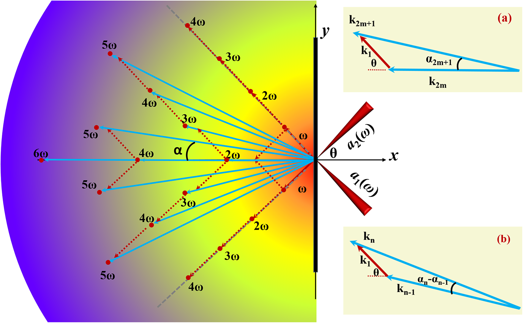
Figure 1 Schematic of the chain selection rule for the proposed approach. Two laser pulses a 1(ω) and a 2(ω), irradiate a thin foil symmetrically at a large crossing angle 2θ, considering the normal direction of the target surface. High-order harmonics are emitted at different spatial locations at an angle α, which is determined by the conservation of energy and linear momentum through the chain selection rule. This chain selection rule is demonstrated by the phase-matching schemes (a) and (b).
As an example, we adopt the z component of the input fields,  ${a}_z={a}_{1z}+{a}_{2z}$, which is related to the harmonics, to analyze the HHG process. Here ${a}_{1z}=\cos \left(\omega t- kx\cos \theta - ky\sin \theta \right)\overset{\frown }{z}$ and ${a}_{2z}=-\cos (\omega t- kx \cos \theta + ky\sin \theta )\overset{\frown }{z}$. The nonlinear part, ${a}_z/\gamma$ (where $\gamma =\sqrt{1+{a}^2}$), in Maxwell’s equation, ${\nabla}^2a-{\partial}^2a/\partial {t}^2={na}_z/\gamma$, contributes to the harmonic generation (where n is the particle density). After the Fourier expansion of this source term, we can derive the expressions for the harmonics generated, as follows:
 $$\begin{align}\left\{\cos \left[2m\left(\omega t- kx\cos \theta \right)+\omega t- kx\cos \theta - ky\sin \theta \right]\right.\notag\\{}\left.+\cos \left[2m\left(\omega t- kx\cos \theta \right)+\omega t- kx\cos \theta + ky\sin \theta \right]\right\}\overset{\frown }{z},\end{align}$$
which can be simplified as  $\sim [\cos (m\cdot 2{\omega}_xt+{\omega}_{a1z}t)+ \cos (m\cdot 2{\omega}_xt+{\omega}_{a2z}t)]\overset{\frown }{z}$, where ${\omega}_xt\sim \left(\omega t- kx\cos \theta \right)$, ${\omega}_{a1(2)z}t\sim \left(\omega t- kx\cos \theta \mp ky\sin \theta \right)$, and m = 0, 1, 2, …. This term highlights the selection processes for generating harmonics. That is, some odd harmonics are produced by the even harmonics propagating in the x direction coupled with the input laser a 1 or a 2, such as the third and fifth harmonics, as shown in Figure 1. Based on this, we can infer that each harmonic carrying the information of both input lasers is formed by lower-order harmonics coupled with one of the input lasers. The expected chain selection rule for the generation of harmonics is shown in Figure 1 and the corresponding phase matching schemes are demonstrated in detail in Figures 1(a) and 1(b). Basically, for n = 2m order harmonics, one photon of which stems from m photons of a 1 and m photons of a 2, the propagating direction is normal to the target (emission angle α = 0), and the coordinate in k-space is (n, 0). Otherwise, one photon of the nth-order harmonic is transformed by one photon of its adjacent (n – 1)th-order harmonic, which has the smallest crossing angle with the nth harmonic owing to the highest occurrence possibility, and one photon of the input laser. According to this chain selection rule, the emission angle ${\alpha}_n$ and the coordinate (knx, kny) in k-space can be predicted by
 $$\begin{align}\tan {\alpha}_n=\frac{\sin \theta +\left(n-1\right)\sin {\alpha}_{n-1}}{\cos \theta +\left(n-1\right)\cos {\alpha}_{n-1}},\notag\\{}\left({k}_{nx},{k}_{ny}\right)=\left(n\cos {\alpha}_n,n\sin {\alpha}_n\right).\end{align}$$
We verify this rule in the following section using 3D PIC simulations, which are also considered as numerical experiments.
3 3D PIC simulations
The PIC simulation configuration is shown in Figure 2(a). The simulations are carried out using the EPOCH code[Reference Arber, Bennett, Brady, Lawrence-Douglas, Ramsay, Sircombe, Gillies, Evans, Schmitz, Bell and Ridgers35]. Two CP laser pulses, a 1 and a 2, with the same frequency ω (the corresponding wavelength λ=1 μm) reach the target at the same angle θ=π/4 symmetrically. A peak normalized amplitude (a 0) of 3 and a focal spot size of 5 μm are used. The laser profile is  ${\sin}^2\left[\pi t/\left(2{t}_0\right)\right]$, where t 0 = 7T and T is the period of the input laser. The simulation box is $20\;\unicode{x3bc} \mathrm{m}\;(x)\times 40\;\unicode{x3bc} \mathrm{m}\;(y)\times 40\;\unicode{x3bc} \mathrm{m}\;(z)$, corresponding to a window with $1000\times 1000\times 1000$ cells and one particle per cell. A thin foil with a thickness of $1\;\unicode{x3bc} \mathrm{m}$ and a density of ${n}_0=20{n}_c$, is employed, where ${n}_c=1.1\times {10}^{21}\ {\mathrm{cm}}^{-3}$ is the critical density for the input laser pulse. Here we note this thin foil is plasma which is initially solid and ionized by the laser pedestal. At $t=0$, the laser pulses enter the simulation box. Considering that the harmonics in the reflected direction are more intense, we focus our analysis on the harmonics in the reflected side from the simulations. As shown in Figure 2(b), where the fundamental frequency components are filtered out, harmonics containing the information of two input pulses are emitted in the reflected side, and they are much more intense than those in the same-rotation case (see Figure s1 in the Supplementary Material).
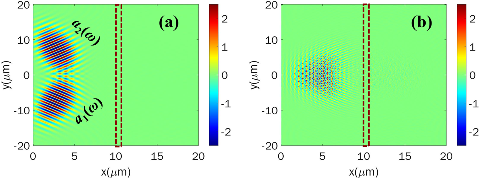
Figure 2 (a) Configuration of the PIC simulation box. The input laser field distribution before the lasers strike the target. (b) Electric field (E z) distribution of the harmonics for two counter-rotation CP lasers after the lasers are reflected completely from the target, where the fundamental components are filtered out. The dashes denote the location of the target. The field is normalized to  ${E}_0={m}_e{\omega}_0c/e$ (3.2×10¹² V/m).
Figure 3 shows the spectrum distribution of the harmonics in k-space after the Fourier transformation of the reflected electric field, E z, in Figure 2(b). As expected, the harmonics include odd and even orders in the reflected directions. The harmonic locations marked with the small white circles in Figure 3 are obtained from Equation (4), showing the good agreement with the simulation results. Harmonics such as 2ω 20, 3ω 30, 4ω 40, 2ω 02, 3ω 03, and 4ω 04 only contain the information of one input laser pulse and propagate along the incident directions. Here we focus on the harmonics containing the information of both input laser pulses. They are generated and angularly isolated, including 2ω 11 of the second harmonic, 3ω 21 and 3ω 12 of the third harmonics, and 4ω 22, 4ω 31, and 4ω 13 of the fourth harmonics, as shown in Figure 3. The propagating directions of these harmonics are determined by vector addition according to their generation way, in which the phase-matching rule should be satisfied.
For example, there are four ways to generate the third harmonics in the photon picture according to energy conservation, i.e., 3ω=3×1ω (a 1), 3ω=3×1ω (a 2), 3ω=2ω+1ω (a 1), 3ω=1ω (a 2) +2ω. However, it implies there are four different emission directions, as shown with 3ω 30, 3ω 03, 3ω 21, and 3ω 12 in Figure 3, because of the different phase-matching relation. Harmonics 3ω 30 or 3ω 03, are undoubtedly emitted along the incident directions because only one linear momentum is related. However, for the other two ways, it is questionable that the photon with an energy of 2ω originates from 2ω 20, 2ω 02, or 2ω 11. Taking 3ω 21 as an example, each photon of 3ω 21 may be transformed by one photon of a 1 and one photon of 2ω 11, or by one photon of a 2 and one photon of 2ω 02 (this selection rule is the same as that in non-collinear gas HHG). For the former, according to Equation (4), the coordinate of 3ω 21 in the k-spectrum distribution should be (2.9, 0.76), and the emission angle (α) should be 0.25 rad. Conversely, for the latter, the coordinate of 3ω 21 in the k-spectrum distribution should be (2.85, 0.95), and the emission angle should be 0.32 rad. The former selection rule is evidenced by the PIC simulations, as shown in Figure 3. In addition, according to our chain selection rule, each photon of 4ω 31 should be transformed by one photon of a 1 and one photon of 3ω 21, and its coordinate in the k-spectrum distribution is expected to be (3.71, 1.5) and the emission angle 0.37 rad, instead of the (3.58, 1.79) coordinate and the 0.464 rad emission angle in the gas HHG way (one photon of a 2 and one photon of 3ω 30). This expectation is also confirmed by the simulation result in Figure 3.

Figure 3 The spectrum distribution of harmonics in k-space corresponding to that in Figure 2(b). Here 2ω 11 is the second harmonic in the direction normal to the target; 3ω 30, 3ω 21, 3ω 12, and 3ω 03 are the third harmonics emitted in different directions; 4ω 40, 4ω 31, 4ω 22, 4ω 13, and 4ω 04 are the fourth harmonics emitted in different directions; and 5ω 32 and 5ω 23 are the fifth harmonics emitted in different directions. The small white circles indicate the harmonics derived from the new phase matching selection rule Equation (4). The blue dashed lines indicate that same order harmonics in different directions have the same wavenumber.
To further verify this conclusion, we show the second harmonic (2ω 11), third harmonic (3ω 21), and the fourth harmonic (4ω 31) in Figure 4. Figures 4(d)–4(f) demonstrate the electric field distributions of the constant phase planes, where the emission angle is selected according to Equation (4). The distributions meet our expectations. We also note that the intensities of the relatively low-order harmonics are in the relativistic range in the present a 0 = 3 case, with the normalized amplitude around 1, basically following the high energy conversion efficiency rule in plasma HHG. The emission angle is about two orders of magnitude higher than that (usually, in the milliradian level) in the non-collinear gas HHG.

Figure 4 Electric field (E z) distributions of the (a), (d) second harmonic (2ω 11), (b), (e) third harmonic (3ω 21), and (c), (f) fourth harmonic (4ω 31) in the (a)–(c) x–y plane at z = 0, and (d)–(f) are the section planes taken along the black dashed lines in (a)–(c).
4 Discussion
Here, two points are elucidated. According to the angular momentum conservation, the n = 2m order harmonics in the normal direction should be linearly polarized, because one photon of such harmonics stems from m photons of a 1 and m photons of a 2, and the total spin angular momentum is zero. The other harmonics are circularly (or elliptically) polarized, because one photo of such harmonics is transformed by one photon of its adjacent (n – 1)th-order harmonic and one photon of the input laser (CP laser). In fact, the PIC simulation result confirms this point; see the k-space spectrum distribution of E y in the Supplementary Material where the even harmonics in the normal direction are missing. We also compared these results with those obtained in the cases of purely linearly polarized incident beams. In the case of p-polarized laser case, harmonics include both the odd and even orders in y component. In the case of s-polarized case, there are only odd order harmonics in z component and even order harmonics in y component. These results are in agreement with the conclusion in Ref. [Reference Lichters, Meyer-ter-Vehn and Pukhov10]. The emission angle for the same order harmonic is identical with that in the CP incident lasers case because it is determined by the same selection rule. Second, phase matching ensures that there is no wave vector mismatch between the emitted harmonics and the input beams which contributes to its emission, usually in the case of small enough crossing angle between the input beams, and these harmonics at different locations can hardly be distinguished spatially. However, in the present large crossing angle geometry, the projection of the input beam wave vectors along the harmonic emission direction should be considered, which results in a phase mismatch, expressed as  $\Delta k={k}_n-{k}_{n-1}\cos \left({\alpha}_n-{\alpha}_{n-1}\right)-{k}_{1(2)}\cos \left(\theta -{\alpha}_n\right)$. As demonstrated in Figures 1 and 3, the harmonic wave vector is slightly larger than the sum of the wave vector projections of the beams which contributes to the harmonic. In this case, the phase matching must be accomplished by considering the whole interaction system including the plasma.
For the HHG from the laser–plasma interaction, one of the most significant findings is that the roll-off of the harmonic spectrum exhibits a power-law dependence of Iωn ~ ω -8/3, and the cutoff frequency increases with the laser intensity by ω cut-off ~ IL 2.5[Reference Baeva, Gordienko and Pukhov11, Reference Teubner, Pretzler, Schlegel, Eidmann, Forster and Witte34]. Our results basically follow these findings for the same plasma HHG mechanism. Our selection rule is still valid for the different intensities and crossing angles, confirmed by additional simulations in the cases of a 0 = 0.2, 0.5, 3, 10, 20, 50 when the half crossing angle is π/4 and a 0 = 3 when the half crossing angle is π/8 and π/3. That is, for the same crossing angle, the intensity and cut-off frequency of the harmonics rise with the input laser intensity. On the other hand, for the same input lasers, the superposed electric field acting on electrons in the surface layer will be strengthened with the decrease of the crossing angle, which will also enhance the harmonics and extend the cut-off frequency. According to the simulation results, we found the conversion efficiency follows the power-law dependence of ~ω -4.1 as shown in Figure 5(a) for the harmonics in the reflected directions. For the same order harmonics emitted at different angles, the conversion efficiency (intensity) decreases with the emission angle, as shown in Figure 5(b).

Figure 5 (a) Energy conversion efficiency for the harmonics in the reflected directions. (b) Energy conversion efficiency for the harmonics of the same order emitted at different angles.
Although the emission angles of the harmonics obtained from the phase-matching equation agree well with the simulation results, we find a slight angle mismatch, as shown in Figures 3 and 4. The main reason is the deformation of the surface plane and Doppler effect of the reflected laser pulse. If the highly relativistic laser pulse is used, the radiation pressure dominates in the laser–plasma interaction, and there will be a curve for the surface electron layer, which may deflect the reflected pulses and impact the emission angle slightly. At the same time, red shift effect will occur for the lasers (harmonics) reflected from the election layer. We know that the motion velocity of the surface electron layer increases with the laser intensity and decreases with the target density, i.e.,  ${v}_p\propto a/\sqrt{n}$[Reference Ji, Shen, Li, Wang, Leng, Zhang, Wen, Wang, Xu and Yu36–Reference Macchi, Cattani, Liseykina and Cornolti39]. For the same target density, the velocity of the surface electron layer increases with the laser intensity, which broadens the spectrum of the harmonics. However, for the given high-density target, our theoretical model is still predictable for the highly relativistic laser case, though the harmonic spectrum would be slightly modulated, as shown by the comparison of the results of different laser intensity cases in Figure 6.

Figure 6 The spectrum distribution of harmonics in k-space after the lasers are reflected completely from the target, where the fundamental components are filtered out in the cases of (a) a 0 =10, (b) a 0=20, and (c) a 0=50.
Harmonics can also be modulated angularly directly from laser irradiated gratings, which has been demonstrated theoretically and experimentally. The approach using a single-beam scheme with grating targets results from the target (grating) modulation directly. In our approach, by overlapping two non-collinear lasers on the plasma target, the spatial structure of the driving field is imprinted on the electron dynamics and, hence, on the harmonic generation. The generated harmonics contain the information of the two incident laser pulses, and thus one can adjust the incident lasers for the different harmonic emission. Most importantly, we found the new phase-selection rule, which is the feature for the non-collinear plasma HHG mechanism, and the harmonic emission direction can be obtained. In addition, the non-collinear plasma HHG process is not limited to mixing two input beams of the same wavelength. When two-color input pulses are used, the selection rule is more complicated because there are additional electron oscillation frequencies except 1ω and 2ω which determines the HHG process. The selection rule of the phasing matching to generate harmonics is similar to what we obtained.
The computational precision in the PIC simulation may also affect the simulation results, particularly for those of order higher than the fourth. We check this by conducting another two-dimensional (2D) PIC simulation with 10,000×10,000 grids instead of 1000×1000 for the x×y window in the aforementioned 3D simulation. Apparently, there is nearly no difference between the harmonics in this case and those analyzed earlier (see the k-space spectrum distribution in the 2D case in the Supplementary Material).
5 Conclusion
In summary, we have proposed an approach, based on the non-collinear plasma HHG process, for generating angularly isolated harmonics at large emission angles. When two counter-rotation CP lasers hit a plasma target at the same side in V-shape, the harmonics carrying the information of the two input lasers are isolated. Using the momentum vector addition of photons, the propagating direction has been obtained. With the present scheme, the origin of these harmonics radiated in the relativistic laser and plasma interaction was elucidated for the first time. Both theoretical analysis and 3D PIC simulations confirmed the newly derived phase-matching selection rule for generating high harmonics. Thus, it is meaningful for practical applications and for understanding the plasma HHG process.
Multi-angle imaging is a potential application for these angularly isolated harmonics. Conventionally, to obtain more detailed imaging information, more than one laser pulses with different wavelengths are required to probe the sample simultaneously from different directions. The application of multiple pump lasers in an optical band will challenge the experimental layout and temporal synchronization. Therefore, angularly isolated multi-wavelength lasers generated simultaneously using the non-collinear HHG approach present significant application promise, particularly in biomedical imaging and material detection. In addition to such application as the gas harmonic source, one can extend its application in laser–plasma interaction, taking advantage of the high intensity of the plasma harmonic source. Although the plasma harmonic source has not efficiently been used so far owing to the strict requirement for the laser condition (intensity, contrast, etc.), there are some exclusive advantages for this harmonic source, such as high intensity/flux and large crossing angle, and this will certainly broaden the application field. Moreover, with the development of the laser technique and the experimental skill, the plasma harmonic source application is expected to flourish in the near future.
Supplementary Materials
To view supplementary material for this article, please visit http://dx.doi.org/10.1017/hpl.2021.14.
Acknowledgements
The authors acknowledge funding from the National Natural Science Foundation of China (Nos. 11922515, 11674339, and 11335013), the National Key R&D Program of China (Nos. 2018YFA0404803 and 2016YFA0401102), the Strategic Priority Research Program of the Chinese Academy of Sciences (No. XDB16), and the Innovation Program of Shanghai Municipal Education Commission.


 Open access