





1 Introduction
Mid-infrared (mid-IR) laser sources are invaluable in modern surgery, medical diagnostics, material processing and industrial or ecological remote sensing[ Reference Wang, Zhang, Liu, Song and Zhang 1 – Reference Nazarov, Kozlova and Tarabrin 4 ]. Among different types of such sources, optical parametric oscillators (OPOs) allow generation in a wide range of wavelengths due to the principle of their operation being based on optical gain from parametric amplification in nonlinear crystals rather than on stimulated emission of radiation. For that, the pump beam is usually tightly focused near the surface or in the bulk of nonlinear crystals, as higher energy intensities improve the nonlinear conversion efficiency.
Therefore, one of the main limits in power scaling of OPOs is laser-induced damage of the nonlinear crystal. By the current ISO standard regulating the matter, for a specific set of incident laser irradiance parameters, the value at which no extrapolated damage probability exists is determined as the laser-induced damage threshold (LIDT)[ 5 ]. With respect to the case of mid-IR OPOs, the problem with the LIDT is aggravated by the usage of antireflection thin-film coatings, which are necessary due to the usually relatively high index of refraction of materials used as nonlinear media for OPOs. Antireflection dielectric coatings (ARCs) tend to have a lower LIDT than substrates if the coating is not designed specifically for the case in question. Such designs of multilayer dielectric coatings include correct choice of materials and adjusting thicknesses and the order of layers in a way to redistribute the electromagnetic field inside the dielectric layers. However, the pursuit of a higher LIDT applies additional design constraints and can become unfeasible, especially if the coating should work for a wide range of wavelengths, which is the case with OPOs.
A novel LiGaS2 crystal is one of the most prospective wide band-gap mid-IR nonlinear crystals. It has already proved itself well in both nanosecond and picosecond parametric down-converters pumped at a wavelength of 1.06 μm because of the high LIDT at 1.06 μm of 3.5 J $\cdot$
cm
$\cdot$
cm ${}^{-2}$
for a 14 ns pulse duration[
Reference Tyazhev, Vedenyapin, Marchev, Isaenko, Kolker, Lobanov, Petrov, Yelisseyev, Starikova and Zondy
6
] and 0.65 J
${}^{-2}$
for a 14 ns pulse duration[
Reference Tyazhev, Vedenyapin, Marchev, Isaenko, Kolker, Lobanov, Petrov, Yelisseyev, Starikova and Zondy
6
] and 0.65 J $\cdot$
cm
$\cdot$
cm ${}^{-2}$
for a 20 ps pulse duration[
Reference Smetanin, Jelínek, Kubeček, Kurus, Vedenyapin, Lobanov and Isaenko
7
] in comparison with other mid-IR nonlinear crystals[
Reference Isaenko and Yelisseyev
8
]. The problem is high Fresnel losses of 12.6% per face due to the high refractive index of the crystal of 2.1. Therefore, for its efficient operation, it is necessary to apply ARC despite the low LIDT.
${}^{-2}$
for a 20 ps pulse duration[
Reference Smetanin, Jelínek, Kubeček, Kurus, Vedenyapin, Lobanov and Isaenko
7
] in comparison with other mid-IR nonlinear crystals[
Reference Isaenko and Yelisseyev
8
]. The problem is high Fresnel losses of 12.6% per face due to the high refractive index of the crystal of 2.1. Therefore, for its efficient operation, it is necessary to apply ARC despite the low LIDT.
However, there is an alternative solution to minimize Fresnel losses. Antireflection microstructures (ARMs) can be applied to achieve lowered Fresnel reflection in a wide range of wavelengths, especially in the mid-IR range of the electromagnetic spectrum. The method is actively researched and has been applied to a variety of materials[ Reference Chattopadhyay, Huang, Jen, Ganguly, Chen and Chen 9 – Reference Han, Wang, Feng, Li, Mu, Zhang, Niu and Ren 12 ]. The ARM usually represents a system of periodic cavities or protrusions of characteristic sizes in the range from hundreds of nanometers to several micrometers. There is a great deal of research that assesses and optimizes the antireflection capabilities of ARMs[ Reference Bushunov, Tarabrin and Lazarev 10 , Reference Boden and Bagnall 13 , Reference Deinega, Valuev, Potapkin and Lozovik 14 ]; however, little research has been done on the LIDT testing of ARMs. The few existing publications[ Reference Du, Liu, He, Jin, Kong and Guan 15 , Reference Hobbs, Macleod, Sabatino, Mirov, Martyshkin, Mirov, Tsoi, McDaniel and Cook 16 ] show that ARMs typically demonstrate significantly higher LIDT values compared to ARCs and therefore present a promising alternative to them, especially for applications where operation in a wide range of wavelengths without compromising the LIDT is desired. Therefore, this work aims to provide detailed LIDT tests of prospective LiGaS2 crystals with ARMs and ARCs applied to minimize Fresnel losses.
2 Experimental setup
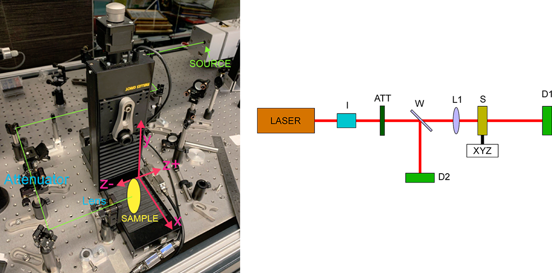
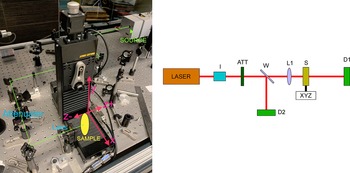
The LIDT measurement setup used consisted of a laser source, a Glan prism polarizer used for beam attenuation, a focusing 50 mm CaF2 lens and automated sample positioning equipment. The setup scheme is presented in Figure 1. For all tests, a single pulse per test site (one-on-one test) was focused with the lens on the sample surface. The tests were carried out in ambient air without purging.
Setup photo and scheme.
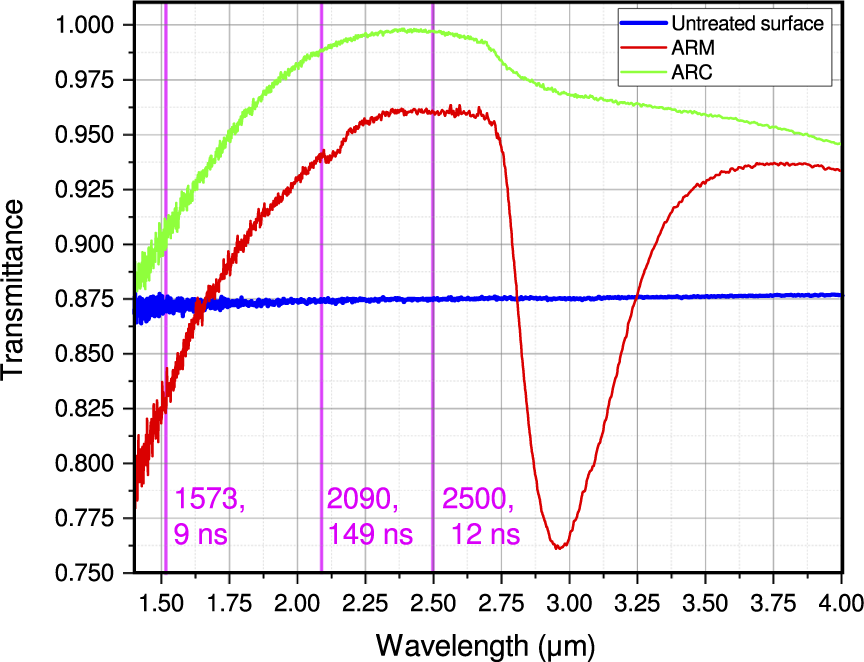
In total, six samples of a LiGaS2 nonlinear crystal were tested. The crystals were grown in the Laboratory of Crystal Growth of Novosibirsk State University using the modernized Bridgman–Stockbarger method with a controlled heat exchanger under conditions of low temperature gradients[ Reference Kurus, Lobanov, Grazhdannikov, Shlegel and Isaenko 17 ]. Prior to the ARM and ARC application, the samples met the quality standard of optical elements used in laser systems: plane-parallel plates with an optical finish specified as 30/20 (scratches/digs). Two samples were left untreated, while both sides of two other samples were coated with ARCs, and on one surface of the remaining two, ARMs were fabricated. The respective transmittance spectra are presented in Figure 2. The transmittance of the ARMs has the typical[ Reference Bushunov, Tarabrin and Lazarev 10 ] form, with a wide peak and a drop at shorter wavelengths due to diffraction and scattering. Radiation diffraction and scattering become prominent at 2.25 μm. The transmittance drop near 3 μm is due to absorption of O-H groups trapped within the ARM and is a side-effect of our fabrication process as applied specifically to LiGaS2. It is similar to ARMs fabricated earlier on samples of LiGaSe2 crystals[ Reference Teslenko, Bushunov, Isaenko, Shklyaev, Goloshumova, Lobanov, Lazarev and Tarabrin 18 ]. A post-process to alleviate this effect is currently under development, but was not applied to the crystal samples used in this work. The applied ARC was a generic single-layer Al2O3 coating, not specifically optimized for high LIDT, due to the limited selection of materials that can be reliably deposited on LiGaS2. Both the ARM and ARC are therefore optimized for the signal wave output in the range from 2 to 2.75 μm, while allowing pumping at shorter wavelengths with reflection losses comparable to the Fresnel losses of an untreated crystal.
Single-surface transmittance of untreated LiGaS2 samples and LiGaS2 samples with ARMs and ARCs applied.
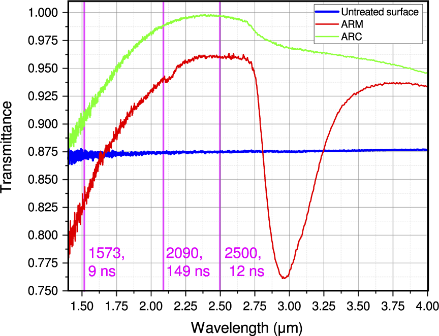
Supposedly, scattering and diffraction not only affect the transmittance of ARMs but also, at the same time, decrease the LIDT due to local concentrations of energy in the cavities and defects of the ARM. To check this, in this work three distinct sources with widely spaced wavelengths were used. The three wavelengths for which the LIDT tests were carried out are marked on the transmittance graph in Figure 2 by vertical magenta lines. The 1.57 μm wavelength is in the spectral region affected by diffraction and scattering on ARMs, the 2.5 μm wavelength is in the spectral region where ARMs should transmit optimally and the wavelength of 2.09 μm is in the transitional spectral region.
Each laser source was characterized by measuring the effective beam diameter[ 5 ] in the beam waist (where the sample was placed for LIDT measurement). These measurements were performed with a Pyrocam IV beam profiler (Ophir Photonics, Israel). However, an alternative knife edge technique[ Reference De Araújo, Silva, De Lima, Pereira and De Oliveira 19 ] was used if the focused beam size was close to the beam profiler pixel size (80 μm).
The first source was a parametric amplifier system that provided 35 mJ pulses at a 1.57 μm wavelength, which is close to a short-wavelength edge of the wavelength region of antireflection of the ARM investigated in this work (Figure 2). The radiation source had a pulse duration of 9 ns at a repetition rate of 100 Hz. The output beam profile measured by a beam profiler was close to Gaussian. The measured effective beam diameter in the focused beam waist was 307 μm, the confocal parameter was near 4 mm and the quality factor was M 2 = 9.2.
The second source was a homemade, tunable in the spectral range from 1.98 to 3.03 μm, Cr ${}^{2+}$
:ZnSe laser with a maximum pulse energy of 2.4 mJ, a pulse duration of 12 ns and a pulse repetition rate of 100 Hz. The wavelength of 2.5 μm was selected because of the maximum transmittance of the ARM and ARC under study (Figure 2). The output beam profile measured by a beam profiler was close to Gaussian. The measured effective beam diameter in the focused beam waist was 83 μm, the confocal parameter was near 1.3 mm and the quality factor M
2 = 1.7.
${}^{2+}$
:ZnSe laser with a maximum pulse energy of 2.4 mJ, a pulse duration of 12 ns and a pulse repetition rate of 100 Hz. The wavelength of 2.5 μm was selected because of the maximum transmittance of the ARM and ARC under study (Figure 2). The output beam profile measured by a beam profiler was close to Gaussian. The measured effective beam diameter in the focused beam waist was 83 μm, the confocal parameter was near 1.3 mm and the quality factor M
2 = 1.7.
The third source was a homemade Ho ${}^{3+}$
:yttrium aluminum garnet (YAG) laser at a 2.09 μm wavelength, also located within the wavelength range of antireflection of the ARM under study. The laser was Q-switched using a frustrated total internal reflection device[
Reference Gagarskii, Galagan, Denker, Korchagin, Osiko, Prikhod'ko and Sverchkov
20
] that provided long laser pulses with an energy of up to 9 mJ and an effective duration of 149 ns at a repetition rate of 1 Hz. The measured effective beam diameter in the focused beam waist was 234 μm with beam quality factor M
2 = 4.2.
${}^{3+}$
:yttrium aluminum garnet (YAG) laser at a 2.09 μm wavelength, also located within the wavelength range of antireflection of the ARM under study. The laser was Q-switched using a frustrated total internal reflection device[
Reference Gagarskii, Galagan, Denker, Korchagin, Osiko, Prikhod'ko and Sverchkov
20
] that provided long laser pulses with an energy of up to 9 mJ and an effective duration of 149 ns at a repetition rate of 1 Hz. The measured effective beam diameter in the focused beam waist was 234 μm with beam quality factor M
2 = 4.2.
The laser-induced damage mechanisms are dependent on pulse duration, inclining to thermally mediated effects for longer pulse durations. LIDT testing at 2.09 μm with longer 149 ns pulse duration makes it possible to enhance the effect of the thermal mechanism of damage in the presence of thermal resistance between the crystal and the ARC or ARM. Moreover, whereas the ARM transmittance near 2.09 μm is close to the peak, it is still in spectral region affected both by diffraction and scattering.
In general, experiment procedures and experimental data processing were carried out in accordance with the standard for one-on-one measurements[ 21 ], with certain exclusions related to the limitations of the actual experimental setup, noted next.
To verify damage, post-experiment analysis of the samples was employed using simple optical microscopy. As a damage criterion, any observable change in transmitted or reflected illumination was considered. As a value for the LIDT, linear approximation extrapolation was used to determine the minimal fluence at which volumetric or surface damage occurred.
Each test sample was 7 mm × 7 mm × 2 mm in size; however, because the sample was mounted in a holder, the test surface area available was approximately 5.5 mm × 5.5 mm. Such a limited area is not sufficient to arrange enough test sites with proper spacing. Therefore, measurements were conducted in two steps. At first, a preliminary test was conducted in a wide range of pulse energies but with a relatively small number of test sites spaced widely. In this step, the coarse estimate for the LIDT and the typical diameter of the damaged spot are acquired. In the next step, the other, pristine sample was tested in the range of pulse energies near the coarsely estimated LIDT, now with a much larger number of test sites (150–200 sites depending on the available space and determined typical damaged spot diameter). This second experiment allows for a statistical LIDT estimation.
3 Experimental results
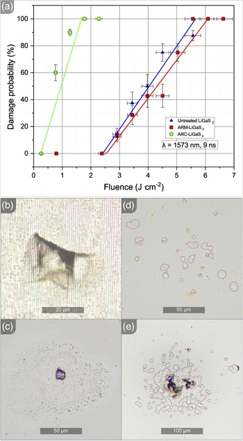
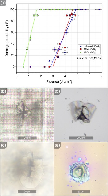
For 1.57 μm, 9 ns LIDT testing, 244 test spots were analyzed both for untreated and microstructured samples, totaling 488 experiments. This allowed for a sufficient statistical estimation of the LIDT. The results of the measurement are presented in Figure 3(a).
LIDT test with 1.57 μm 9 ns pulses: (a) LIDT measurement data; (b) typical damage site of the ARM; (c) typical damage site of the untreated substrate; (d) typical damage of the ARC; (e) catastrophic damage of the ARC.
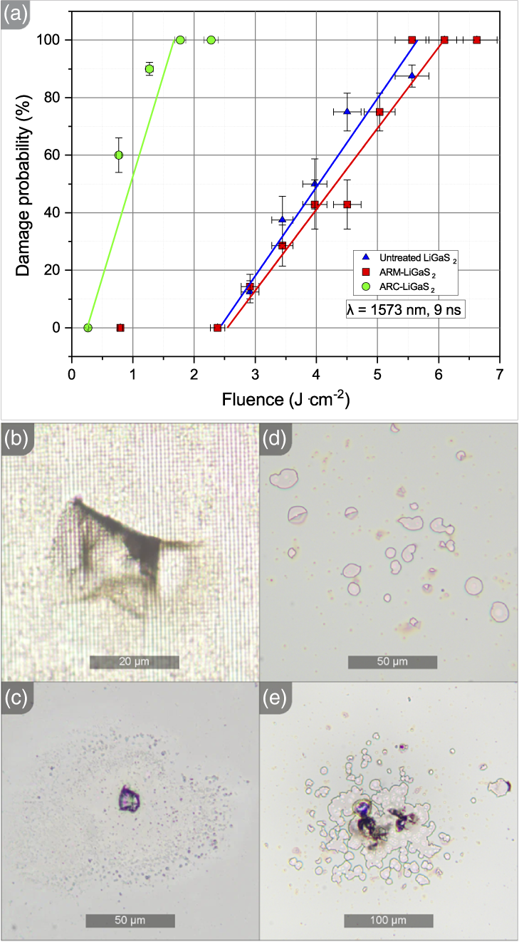
The estimated LIDT is 2.45 J $\cdot$
cm
$\cdot$
cm ${}^{-2}$
for untreated and 2.56 J
${}^{-2}$
for untreated and 2.56 J $\cdot$
cm
$\cdot$
cm ${}^{-2}$
ARM-treated LiGaS2. Figure 3(b) shows the typical damaged site of the ARM, with a mean diameter close to 35 μm. Figure 3(c) shows the typical damaged site of the untreated surface, with a mean diameter close to 15 μm. Damage to the ARM occurred mainly on the surface of the sample, while damage to the untreated sample occurred both on the surface and in the volume of the crystal (nearly 200 μm underneath the surface) at an even ratio. The LIDT of the tested ARC is 0.36 J
${}^{-2}$
ARM-treated LiGaS2. Figure 3(b) shows the typical damaged site of the ARM, with a mean diameter close to 35 μm. Figure 3(c) shows the typical damaged site of the untreated surface, with a mean diameter close to 15 μm. Damage to the ARM occurred mainly on the surface of the sample, while damage to the untreated sample occurred both on the surface and in the volume of the crystal (nearly 200 μm underneath the surface) at an even ratio. The LIDT of the tested ARC is 0.36 J $\cdot$
cm
$\cdot$
cm ${}^{-2}$
, nearly seven times lower in comparison to the LIDT of the untreated surface and ARMs. Figures 3(d) and 3(e) show the typical damaged site of the antireflection-coated surface. Diameters of damage sites for the ARC are much larger: in the range from 100 to 200 μm for both typical and catastrophically damaged sites and comparable with a beam spot size of 300 μm.
${}^{-2}$
, nearly seven times lower in comparison to the LIDT of the untreated surface and ARMs. Figures 3(d) and 3(e) show the typical damaged site of the antireflection-coated surface. Diameters of damage sites for the ARC are much larger: in the range from 100 to 200 μm for both typical and catastrophically damaged sites and comparable with a beam spot size of 300 μm.
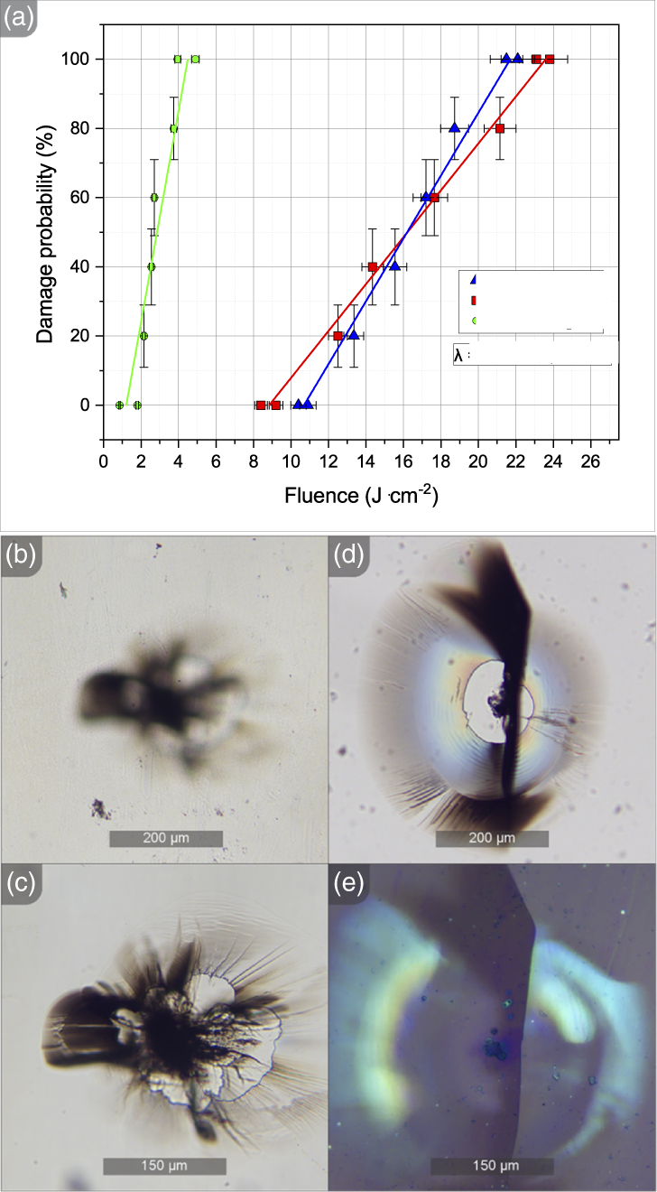
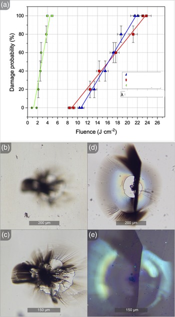
For 2.5 μm, 12 ns LIDT testing, 100 test spots were analyzed for each of the samples, including untreated, ARC and ARM samples, totaling 300 experiments. The results of the measurement are presented in Figure 4(a).
LIDT test with 2.5 μm, 12 ns pulses: (a) LIDT measurement data; (b) typical damage site of the ARM, focused on the surface; (c) typical damage site of the ARM, focused on volumetric damage underneath the surface damage; (d) typical damage site of the untreated substrate; (e) typical catastrophic damage site of the ARC.
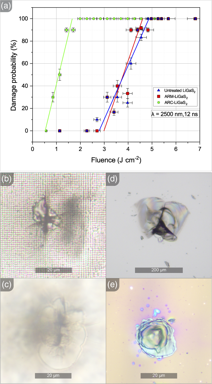
The estimated LIDT is 2.78 J $\cdot$
cm
$\cdot$
cm ${}^{-2}$
for untreated LiGaS
${}^{-2}$
for untreated LiGaS ${}_2$
and 3 J
${}_2$
and 3 J $\cdot$
cm
$\cdot$
cm ${}^{-2}$
for that with ARM applied. Antireflection-coated LiGaS2 demonstrates a 0.52 J
${}^{-2}$
for that with ARM applied. Antireflection-coated LiGaS2 demonstrates a 0.52 J $\cdot$
cm
$\cdot$
cm ${}^{-2}$
LIDT. Figures 4(b) and 4(c) show the typical damage on the surface and in the volume. Both areas of surface and volumetric damage have a diameter close to 40 μm. Figure 4(d) shows the typical damaged site of the untreated surface, with a mean diameter close to 15 μm. Cracking of untreated and ARM samples with surface damage was observed in most cases of LIDT testing with 2.5 μm if compared to 1.57 μm. The samples with ARMs applied in this series of experiments were damaged in volume nearly as frequently as untreated ones. Figure 4(e) shows the catastrophic damage site of the ARC. The damage area mean diameter is near 30 μm. Most of the test sites in our experiments show fairly mild damage to the ARC with no cracking and extensive coating delamination, even at fluence several times the damage threshold value.
${}^{-2}$
LIDT. Figures 4(b) and 4(c) show the typical damage on the surface and in the volume. Both areas of surface and volumetric damage have a diameter close to 40 μm. Figure 4(d) shows the typical damaged site of the untreated surface, with a mean diameter close to 15 μm. Cracking of untreated and ARM samples with surface damage was observed in most cases of LIDT testing with 2.5 μm if compared to 1.57 μm. The samples with ARMs applied in this series of experiments were damaged in volume nearly as frequently as untreated ones. Figure 4(e) shows the catastrophic damage site of the ARC. The damage area mean diameter is near 30 μm. Most of the test sites in our experiments show fairly mild damage to the ARC with no cracking and extensive coating delamination, even at fluence several times the damage threshold value.
Figure 5(a) shows the analogous results of LIDT testing at 2.09 μm, 149 ns. A total of 150 experiments were conducted.
LIDT test with 2.09 μm, 149 ns pulses: (a) LIDT measurement data; (b) typical damage site of the ARM, focused on the surface, in which there is no damage at the surface; (c) typical damage site of the ARM, focused on the volumetric damage, in the same spot as for (b); (d) typical catastrophic damage site of the ARC; (e) typical catastrophic damage site of the ARC, with polarization contrast applied.
As can be seen, the LIDT values with zero probability were significantly higher and amounted to 10.9, 9 and 1.1 J $\cdot$
cm
$\cdot$
cm ${}^{-2}$
for untreated LiGaS2, LiGaS2 with ARMs and LiGaS2 with ARCs, respectively. In this experiment, the general features of the damaged ARM sites resemble those previously demonstrated, with both volumetric and surface damage and moderate cracking in close proximity to the damage site. However, all the damaged sites on the untreated sample have only volumetric damage. Figures 5(b) and 5(c) demonstrate one of these sites. In all experiments, damage occurred at nearly 300 μm below the surface. Both areas of surface and volumetric damage have a diameter close to 400 μm, more than twice the diameter of the beam waist. Figure 5(d) shows the catastrophic damage to the ARC sample. The damaged area is much larger than in the case of the LIDT test at 2.5 μm wavelength and severe cracking is present. Figure 5(e) shows a photo of the same site but with polarization contrasting. Although the initial damage spot is of a size comparable to that of the experiments with a wavelength of 2.5 μm, the resulting cracking and volumetric damage cover an area of more than 500 μm in diameter.
${}^{-2}$
for untreated LiGaS2, LiGaS2 with ARMs and LiGaS2 with ARCs, respectively. In this experiment, the general features of the damaged ARM sites resemble those previously demonstrated, with both volumetric and surface damage and moderate cracking in close proximity to the damage site. However, all the damaged sites on the untreated sample have only volumetric damage. Figures 5(b) and 5(c) demonstrate one of these sites. In all experiments, damage occurred at nearly 300 μm below the surface. Both areas of surface and volumetric damage have a diameter close to 400 μm, more than twice the diameter of the beam waist. Figure 5(d) shows the catastrophic damage to the ARC sample. The damaged area is much larger than in the case of the LIDT test at 2.5 μm wavelength and severe cracking is present. Figure 5(e) shows a photo of the same site but with polarization contrasting. Although the initial damage spot is of a size comparable to that of the experiments with a wavelength of 2.5 μm, the resulting cracking and volumetric damage cover an area of more than 500 μm in diameter.
4 Discussion
All tests demonstrated that the LIDT value of the ARM is basically the same as for the untreated surface of LiGaS2, while the ARC tends to have a nearly six or even seven-fold reduced LIDT in comparison. This is generally consistent with the results obtained in other studies that compared the LIDT of ARCs and ARMs[ Reference Du, Liu, He, Jin, Kong and Guan 15 , Reference Hobbs, Macleod, Sabatino, Mirov, Martyshkin, Mirov, Tsoi, McDaniel and Cook 16 ].
However, the predicted reduced LIDT of ARMs for shorter wavelengths has not been confirmed by the experimental results. The observed decrease (Figure 2) in transmittance for wavelengths shorter than 2.25 μm is usually attributed to scattering on the features of the ARM. This scattering should, in theory, significantly reduce the LIDT. The mechanism is electromagnetic field localization and concentration within the micro-cavities when the laser wavelength is shorter than the ARM period. This localization can produce field amplitude spikes an order of magnitude higher[ Reference Gao, Wang, Jia, Ding, Jiang, Wang and Duan 22 , Reference Weiblen, Florea, Busse, Shaw, Menyuk, Aggarwal and Sanghera 23 ] than in the long-wavelength regime (where the wavelength exceeds the ARM period), ultimately leading to breakdown. This result is quite unexpected and means that the ARM can effectively withstand intense irradiation of the pump in the scattering-affected spectral region (for wavelengths shorter than 1.75 μm), while providing enhanced transmittance for signal and idler waves for longer wavelengths, thus effectively increasing the ARM working range. However, further theoretical and experimental investigation should be conducted to rule out possible misinterpretation of experimental results.
Another experimental finding is that with 1.57 μm radiation the damage to the ARM was mostly localized on the surface of the sample, while untreated LiGaS2 was equally frequently damaged on the surface and in the volume, even though the confocal parameters are larger than the sample thickness. This could be attributed to the scattering that initiates damage on the surface, and indeed, with 2.5 μm radiation the tendency of LiGaS2 with ARM to be damaged in volume is practically the same as that of untreated LiGaS2. However, there is still no decrease in the LIDT for LiGaS2 with ARM at this wavelength.
The increase in LIDT for longer pulses is theoretically explained by the well-known proportionality of the LIDT to the square root of the pulse duration[
Reference Niemz
24
], that is, the values at 149 ns should be higher by $(149/8)^{1/2}$
= 4.3 times than at 8 ns. In fact, this is close to the truth for LiGaS2. However, the value (1.8 J
$(149/8)^{1/2}$
= 4.3 times than at 8 ns. In fact, this is close to the truth for LiGaS2. However, the value (1.8 J $\cdot$
cm
$\cdot$
cm ${}^{-2}$
) for antireflection-coated LiGaS2 turned out to be noticeably lower than expected (0.7
${}^{-2}$
) for antireflection-coated LiGaS2 turned out to be noticeably lower than expected (0.7 $\times$
4.3
$\times$
4.3 $\approx$
3 J
$\approx$
3 J $\cdot$
cm
$\cdot$
cm ${}^{-2}$
). This can be explained as follows. For relatively short pulses with a duration close to 10 ns, dielectric breakdown plays a significant role, while thermally mediated damage is not as pronounced as for longer pulses with a duration up to the order of 100 ns. For these longer pulses, destruction occurs with prominent thermal mechanisms[
Reference Wood
25
]. The predominant thermally mediated damage mechanism can also be attributed to an increase in the damage footprint in tests with longer 149 ns pulses in comparison with shorter 12 and 9 ns pulses. Severe cracking of antireflection-coated crystals (Figure 5) under intense pulsed thermal load is also a known case[
Reference Hobbs, Macleod, Sabatino, Mirov, Martyshkin, Mirov, Tsoi, McDaniel and Cook
16
]. Therefore, the thermal mechanism of the damage leads to the reduced LIDT of the ARC due to the thermal resistance between the LiGaS2 crystal and the ARC. However, for ARMs the LIDT reduction does not occur, as the applied thermal load can spread due to no thermal resistance between the ARM and the volume of the substrate.
${}^{-2}$
). This can be explained as follows. For relatively short pulses with a duration close to 10 ns, dielectric breakdown plays a significant role, while thermally mediated damage is not as pronounced as for longer pulses with a duration up to the order of 100 ns. For these longer pulses, destruction occurs with prominent thermal mechanisms[
Reference Wood
25
]. The predominant thermally mediated damage mechanism can also be attributed to an increase in the damage footprint in tests with longer 149 ns pulses in comparison with shorter 12 and 9 ns pulses. Severe cracking of antireflection-coated crystals (Figure 5) under intense pulsed thermal load is also a known case[
Reference Hobbs, Macleod, Sabatino, Mirov, Martyshkin, Mirov, Tsoi, McDaniel and Cook
16
]. Therefore, the thermal mechanism of the damage leads to the reduced LIDT of the ARC due to the thermal resistance between the LiGaS2 crystal and the ARC. However, for ARMs the LIDT reduction does not occur, as the applied thermal load can spread due to no thermal resistance between the ARM and the volume of the substrate.
5 Conclusion
In the work, the LIDT of the prospective nonlinear LiGaS2 crystal was extensively tested with three distinct laser sources. The LiGaS2 samples were tested with an untreated surface, and surfaces coated with ARC and with ARMs applied. The experimentally determined LIDT values of untreated LiGaS2 are as follows: 2.45 J $\cdot$
cm
$\cdot$
cm ${}^{-2}$
(at 1.57 μm, 9 ns), 11.1 J
${}^{-2}$
(at 1.57 μm, 9 ns), 11.1 J $\cdot$
cm
$\cdot$
cm ${}^{-2}$
(at 2.09 μm, 149 ns) and 2.78 J
${}^{-2}$
(at 2.09 μm, 149 ns) and 2.78 J $\cdot$
cm
$\cdot$
cm ${}^{-2}$
(at 2.5 μm, 12 ns). The experimentally determined LIDT values of antireflection-coated LiGaS2 are as follows: 1.8 J
${}^{-2}$
(at 2.5 μm, 12 ns). The experimentally determined LIDT values of antireflection-coated LiGaS2 are as follows: 1.8 J $\cdot$
cm
$\cdot$
cm ${}^{-2}$
(at 2.09 μm, 149 ns) and 0.52 J
${}^{-2}$
(at 2.09 μm, 149 ns) and 0.52 J $\cdot$
cm
$\cdot$
cm ${}^{-2}$
(at 2.5 μm, 12 ns). The experimentally determined LIDT values of LiGaS2 with ARMs applied are as follows: 2.56 J
${}^{-2}$
(at 2.5 μm, 12 ns). The experimentally determined LIDT values of LiGaS2 with ARMs applied are as follows: 2.56 J $\cdot$
cm
$\cdot$
cm ${}^{-2}$
(at 1.57 μm, 9 ns), 9.2 J
${}^{-2}$
(at 1.57 μm, 9 ns), 9.2 J $\cdot$
cm
$\cdot$
cm ${}^{-2}$
(at 2.09 μm, 149 ns) and 3 J
${}^{-2}$
(at 2.09 μm, 149 ns) and 3 J $\cdot$
cm
$\cdot$
cm ${}^{-2}$
(at 2.5 μm, 12 ns).
${}^{-2}$
(at 2.5 μm, 12 ns).
These results essentially prove that LiGaS2 with ARMs applied can be pumped at shorter wavelengths, while providing increased transmittance for signal and idler waves, all with an LIDT nearly as high as the substrate itself. In a similar scenario, the application of the ARC reduced the LIDT significantly, decreasing damage-safe pump power nearly seven-fold. Thus, implementing nonlinear crystals with ARMs applied in actual parametric systems can significantly improve their energetic characteristics.
Acknowledgements
A.A.B., P.D.K., S.N.S., A.A.G., S.I.L., A.F.K., L.I.I. and M.K.T. acknowledge the Russian Science Foundation (project 20-72-10027-P) for the support of crystal growth, ARM fabrication and LIDT measurements. S.I.L. acknowledges the state assignment of the V.S. Sobolev Institute of Geology and Mineralogy SB RAS (122041400031-2) for the support of charge composition analysis for the crystal synthesis.
Author contributions statement
A.A.B., M.K.T., A.A.G. and S.N.S. conceived the idea of the research. A.A.G., S.I.L., A.F.K. and L.I.I. grew and prepared samples of crystals. P.D.K., Y.M.V. and D.A.N. set up and carried out the LIDT test experiments. A.G.P., S.E.S. and B.I.G. conducted damage site investigation. A.A.B. and S.N.S. performed analysis of the results. S.N.S. and A.A.B. compiled the manuscript. All authors reviewed the manuscript. L.I.I., S.N.S and M.K.T. supervised the work and maintained communication between parts of the research team.

 Open access

