




I. INTRODUCTION
Dissimilar joints of aluminum (Al)–steel have acquired substantial applications in different sectors of industries including majority in automotive, marine, aerospace, and chemical sectors, furthermore, day by day increasing along with development in technologies.Reference Atabaki, Nikodinovski, Chenier, Ma, Harooni and Kovacevic1–Reference Kusuda4 The applications of Al–steel joints such as wind shield frame, bumper reinforcement, center pillar, and floor pan are existed in automotive structures and can be expanded in future.Reference Hussein, Tahir and Hadzley3–Reference Clark5 The use of dissimilar Al–steel joints in a product leads to the sustainable advantages such as reduction of overall cost by considering price differences of both the materials, minimizing weight of the component taking into account density differences of both the materials, benefit on combination of light weight Al to high strength steel material, and hybrid properties availability at two different ends.Reference Shah and Ishak6,Reference Choi, Kim, Nam, Kim and Park7 However, the welding of dissimilar Al–steel materials is complicated due to complexity in compatibility of both the materials during mixing in each other.Reference Shah and Ishak6,Reference Agudo, Eyidi, Schmaranzer, Arenholz, Jank, Bruckner and Pyzalla8 Specific differences in properties of Al and steel materials are mentioned subsequently. The difference in melting temperature between Al and steel is around 850 °C. The ability to form oxides at distinct temperature is contrast for Al and steel materials. The coefficient of thermal expansion and specific heat of the Al material are almost twice than the steel material.Reference Atabaki, Nikodinovski, Chenier, Ma, Harooni and Kovacevic1 The thermal conductivity of the Al material is six times higher than the that of the steel material. The Al material has three times higher modulus of elasticity than steel.Reference Shah and Ishak6 Al and steel are having very poor solubility in each other. The electrochemical difference between Al and steel is 1.22 volts.Reference Atabaki, Nikodinovski, Chenier, Ma, Harooni and Kovacevic1,Reference Shah and Ishak6 These dissimilarities in thermophysical, chemical, and mechanical properties of Al–steel materials lead to disadvantages such as formation of intermetallic compounds (IMCs), heat-affected zone (HAZ), metallurgical precipitation, defects, distortion, and deterioration of mechanical joint properties.Reference Atabaki, Nikodinovski, Chenier, Ma, Harooni and Kovacevic1,Reference Hussein, Tahir and Hadzley3,Reference Shah and Ishak6,Reference Liu, Ma, Mazar Atabaki and Kovacevic9,Reference Ma, Harooni, Carlson and Kovacevic10
Considering these factors, joining processes such as brazing,Reference Sierra, Peyre, Beaume, Stuart and Fras11–Reference Roulin, Luster, Karadeniz and Mortensen13 gas tungsten arc welding (GTAW),Reference Sierra, Peyre, Deschaux Beaume, Stuart and Fras14,Reference Borrisutthekul, Seangsai and Paonil15 gas metal arc welding,Reference Su, Hua and Wu16,Reference Su, Hua and Wu17 metal inert gas welding,Reference Nguyen and Huang18 laser welding,Reference Sierra, Peyre, Deschaux Beaume, Stuart and Fras14,Reference Sun, Yan, Gao and Huang19–Reference Rathod and Kutsuna22 hybrid welding,Reference Mei, Gao, Yan, Zhang, Li and Zeng23–Reference Gao, Chen, Mei, Wang and Zeng26 resistance spot welding,Reference Chen, Yuan, Hu, Sun, Zhang and Zhang27–Reference Chen, Wang, Carlson, Sigler and Wang29 explosive welding,Reference Acarer and Demir30 magnetic pulse welding,Reference Lee, Kumai, Arai and Aizawa31,Reference Aizawa, Kashani and Okagawa32 cold metal transfer,Reference Zhang, Feng, He, Zhang, Chen and Wang33,Reference Zhang, Feng and He34 ultrasonic welding,Reference Tsujino, Hidai, Hasegawa, Kanai, Matsuura, Matsushima and Ueoka35 and friction-based welding processesReference Atabaki, Nikodinovski, Chenier, Ma, Harooni and Kovacevic1,Reference Hussein, Tahir and Hadzley3,Reference Shah and Ishak6 are investigated in different literature studies. Out of all these processes, arc welding processes are viewed as nonrecommended processes to obtain successful dissimilar Al–steel welds based on their process aspects of melting and solidification caused by arc. Besides, friction-based welding can be considered as the most feasible solution to overcome the aforementioned problems associated with dissimilar Al–steel welds by bearing in mind their solid state nature and low heat input conditions.Reference Atabaki, Nikodinovski, Chenier, Ma, Harooni and Kovacevic1,Reference Hussein, Tahir and Hadzley3,Reference Shah and Ishak6 Different friction-based welding processes such as friction welding, friction stir welding (FSW), hybrid friction stir welding (HFSW), friction stir spot welding (FSSW), friction stir spot fusion welding (FSSFW), friction stir scribe welding, friction stir brazing (FSB), friction stir dovetailing (FSD), friction bit joining (FBJ), friction melt bonding (FMB), friction stir extrusion (FSE), and friction stir assisted diffusion welding (FSADW) are analyzed for dissimilar Al–steel joints based on previous literature studies. However, the collective information and comparison of joint formation with different friction-based processes have never been attempted for publication hitherto to the extent of author’s knowledge. There is a need to show collective informations on these literature studies in one single document by taking into account the importance of dissimilar Al–steel joints’ and properties’ variations in the weld area. As a consequence, comprehensive understanding is developed through this article, which showcases details on dissimilar Al–steel joint manufactured by the above-mentioned friction-based welding for its process description, influence of parameters, microstructural variations, formation of IMCs, and variations in mechanical properties.
A. Binary phase diagram and IMCs
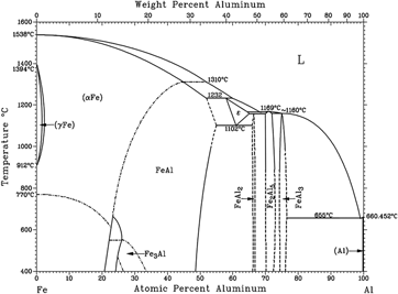
Al and steel materials are having nearly zero mutual solubility that subsequently leads to form IMCs of FexAlx.Reference Springer, Kostka, Payton, Raabe, Kaysser-Pyzalla and Eggeler36 The formation of IMCs is dependent on solid state reactions between these two materials of Fe and Al.Reference Haidara, Record, Duployer and Mangelinck37 Interactions of at.% of Fe and Al materials decide the type of the IMC phase. The binary phase diagram of Fe and Al is shown in Fig. 1 to understand the stand of different IMCs and reactions of Fe and Al with temperature interactions. Parameters such as time, temperature, pressure, and chemical compositions govern the formation of these IMCs, which is consequently depended on welding parameters and process conditions.Reference Springer, Kostka, Payton, Raabe, Kaysser-Pyzalla and Eggeler36,Reference Haidara, Record, Duployer and Mangelinck37 Al and Fe undergo interchanging as a function of small solute diffusion, movement of grain boundaries, and number of vacancies in the scale of atom, during a welding process. It can be seen from Fig. 1 that nonstoichiometric IMCs such as FeAl, FeAl2, Fe3Al, Fe2Al3, Fe2Al5, FeAl3, and FeAl6 are formed during the bonding between Al and steel-based alloys.Reference Atabaki, Nikodinovski, Chenier, Ma, Harooni and Kovacevic1,Reference Springer, Kostka, Payton, Raabe, Kaysser-Pyzalla and Eggeler36,Reference Haidara, Record, Duployer and Mangelinck37 The formation of IMCs are depended on the chemical potential of Al and Fe, phase nucleation at the beginning of interdifusion, and mobility of alloying elements, which are subsequently affected by thermodynamic conditions of the process.Reference Potesser, Schoeberl, Antrekowitsch and Bruckner38 Most of these IMCs are very hard and brittle than the Al and Fe base materials. The IMCs of FeAl2, Fe2Al5, and FeAl3 are most hard compounds among all the mentioned phases, as they consist of hardness more than 1000 VHN.Reference Atabaki, Nikodinovski, Chenier, Ma, Harooni and Kovacevic1,Reference Springer, Kostka, Payton, Raabe, Kaysser-Pyzalla and Eggeler36,Reference Haidara, Record, Duployer and Mangelinck37 Apart from differences in hardness, the crystal structures are distinct for different IMCs. The summary on IMCs of the Al–Fe system for their crystal structures and hardness is presented in Table I. In the case of weld area, the IMCs are generally found in the layer form at the interface between Al and steel materials and that is considered as the weakest part of the weld. Therefore, the presence of IMCs is recommended as minimum as possible in terms of thickness and volume fraction. The type, size, and amount of IMC formation are dependent on heat input that is governed by the welding process parameters. A higher amount of IMCs are formed due to higher heat input; therefore, it is recommended to operate a welding process with less heat input to make dissimilar Al–steel joints.Reference Atabaki, Nikodinovski, Chenier, Ma, Harooni and Kovacevic1,Reference Springer, Kostka, Payton, Raabe, Kaysser-Pyzalla and Eggeler36,Reference Haidara, Record, Duployer and Mangelinck37 There are additional process parameters and some process modifications relative to the conventional process performed to improve the formation of IMCs in different friction-based welding processes. Further description of IMCs can be found in subsequent sections based on different friction-based processes along with important analysis on microstructural features and variations in mechanical properties.
Binary phase diagram of the Al–Fe system, with permission from Ref. Reference Haidara, Record, Duployer and Mangelinck37.
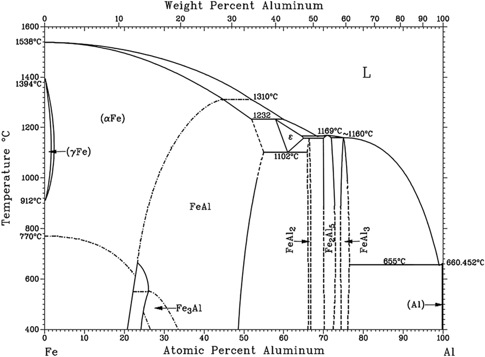
Summary on crystal structure and hardness of different IMCs of the Al–Fe system.Reference Atabaki, Nikodinovski, Chenier, Ma, Harooni and Kovacevic1,Reference Springer, Kostka, Payton, Raabe, Kaysser-Pyzalla and Eggeler36,Reference Haidara, Record, Duployer and Mangelinck37
II. FRICTION WELDING
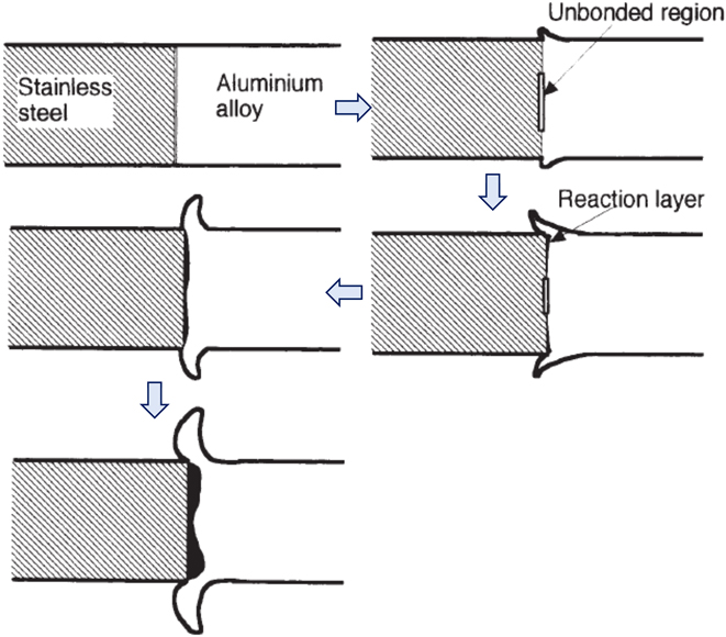
Friction welding is a conventional solid state welding process that uses frictional heat and pressure to obtain welding between parent materials. The frictional heat is generated with the help of relative movement of workpiece materials by means of rotation or reciprocating motions.Reference Meshram, Mohandas and Reddy39,Reference Li, Vairis, Preuss and Ma40 Dissimilar welding of Al–steel can be successfully welded by the friction welding process as solid state welding leads to overcome problems of dissimilar welding.Reference Taban, Gould and Lippold41–Reference Wan and Huang54 Cylindrical rods of Al–steel are generally welded by friction welding as it is most convenient for friction welding methodology. Process parameters such as rotational speed, axial pressure, time associated for heating, special edge preparations, use of interlayer, and holding of a specific material for rotation and stationary position are important as far as dissimilar Al–steel friction steel is concerned.Reference Taban, Gould and Lippold41–Reference Wan and Huang54 Special edge preparations and holding of the workpiece material are unique parameters in addition to the conventional parameters for dissimilar Al–steel friction welding as reported in some of the literature studies.Reference Ashfaq, Sajja, Khalid Rafi and Prasad Rao47,Reference Wan and Huang54 Heat generation in friction welding is mainly dependent on the aforementioned process parameters of rotational speed and time.Reference Kimura, Suzuki, Kusaka and Kaizu50 Hence, the formation of IMCs is majorly governed by these parameters as it is directly influenced by heat generation.Reference Taban, Gould and Lippold41–Reference Wan and Huang54 Subsequently, the mechanical properties especially tensile strength and hardness are affected with variations in IMCs.Reference Taban, Gould and Lippold41,Reference Herbst, Aengeneyndt, Maier and Nürnberger45,Reference Reddy, Rao and Mohandas51 Higher rotational speed and frictional time lead to higher heat generation that consequently increases the formation of IMCs in the weld zone and deteriorated the mechanical properties.Reference Taban, Gould and Lippold41,Reference Herbst, Aengeneyndt, Maier and Nürnberger45,Reference Reddy, Rao and Mohandas51,Reference Wan and Huang54 The reaction layer of IMCs is found at the interface between Al and steel materials. This reaction layer of IMCs is required as thin as possible by controlling process parameters, which is characterized as the better joint phenomenon. The critical reaction layer of IMCs is recommended as thin as 1–2 µm for strong bond strength. However, even thinner than this dimension enhances the mechanical properties of joint.Reference Taban, Gould and Lippold41–Reference Wan and Huang54 The thick layer of IMCs deteriorates the tensile strength and increases hardness while reduces ductility of the joint. The heat distribution is nonuniform in all the directions of the weld interface that in turn form a nonuniform layer of IMCs. The analysis of the Al–steel interface is considered as critical due to the formation of brittle IMCs at this location. Apart from the layer of IMCs at the interface, the random distribution of IMCs is also presented in the weld zone. Different IMC phases of FeAl, Fe2Al5, and FeAl3 are reported in most of the literature studies of Al–steel friction welding.Reference Taban, Gould and Lippold41–Reference Wan and Huang54 The mechanism of solid state diffusion and mechanical intermixing are mainly responsible for the formation of different IMCs.Reference Taban, Gould and Lippold41,Reference Herbst, Aengeneyndt, Maier and Nürnberger45,Reference Reddy, Rao and Mohandas51,Reference Wan and Huang54 The mechanical pressure mainly influences the flash effect which usually occurs at the Al side. Larger mechanical pressure leads to larger deformation of the Al material that in turn causes larger flash effect.Reference Taban, Gould and Lippold41–Reference Wan and Huang54 On the other end, adequate flash of Al is mandatory as bonding between Al and steel starts from the outer region of the faying surface and afterward goes toward the center of the faying surface. Due to this, the formation of the IMC layer is found thicker at the outer region and thinner at center as shown in Fig. 2.
Interlayer formation steps in dissimilar Al–steel friction welding, with permission from Ref. Reference Fukumoto, Tsubakino, Okita, Aritoshi and Tomita42.
Microstructural features are affected by friction welding parameters. In the case of Al and steel base materials of friction welding, Al is the softer material relative to steel that in turn leads to quick and large deformation. Moreover, the heat conductivity of Al is more than that of steel, and, therefore, large microstructural changes are noticed from the Al side due to high heat experiences. Since Al is a softer material than steel, large deformation of Al is obvious that consequently leads to large flash effect and microstructural changes at the Al side in the case of friction welding.Reference Taban, Gould and Lippold41,Reference Herbst, Aengeneyndt, Maier and Nürnberger45,Reference Reddy, Rao and Mohandas51,Reference Wan and Huang54 There are four different microstructural changes reported at the Al side while another four microstructural changes are observed at the interface between Al–steel joint by Wan and Huang et al.Reference Wan and Huang54 as shown in Fig. 3(a). The interface microstructure is important to understand considering the complexity of dissimilar Al–steel friction welded joints. The thickness of the reaction layer can be estimated under the diffusion process control by the equation of X = √t [K o·exp(−Q/RT)],Reference Shah and Ishak6,Reference Fukumoto, Tsubakino, Ono, Aritoshi, Tomita and Okita43 where X is the thickness of the reaction layer (mm), t is the diffusion time (s), K o is a constant, Q is the activation energy (J) for the growth of the layer, R is the gas constant, and T is the absolute temperature (K).
Microstructural features of dissimilar Al–steel friction welds (a) Al–steel interface and different zones at Al sides, (b) solid solution zone at interface-region D of (a), (c) partial secondary recrystallized zone at Al-region E of (a), (d) recrystallized zone at Al-region F of (a), (e) partial recrystallized zone-region G of (a), (f) plastic deformation zone-region H of (a), with permission from Ref. Reference Wan and Huang54.
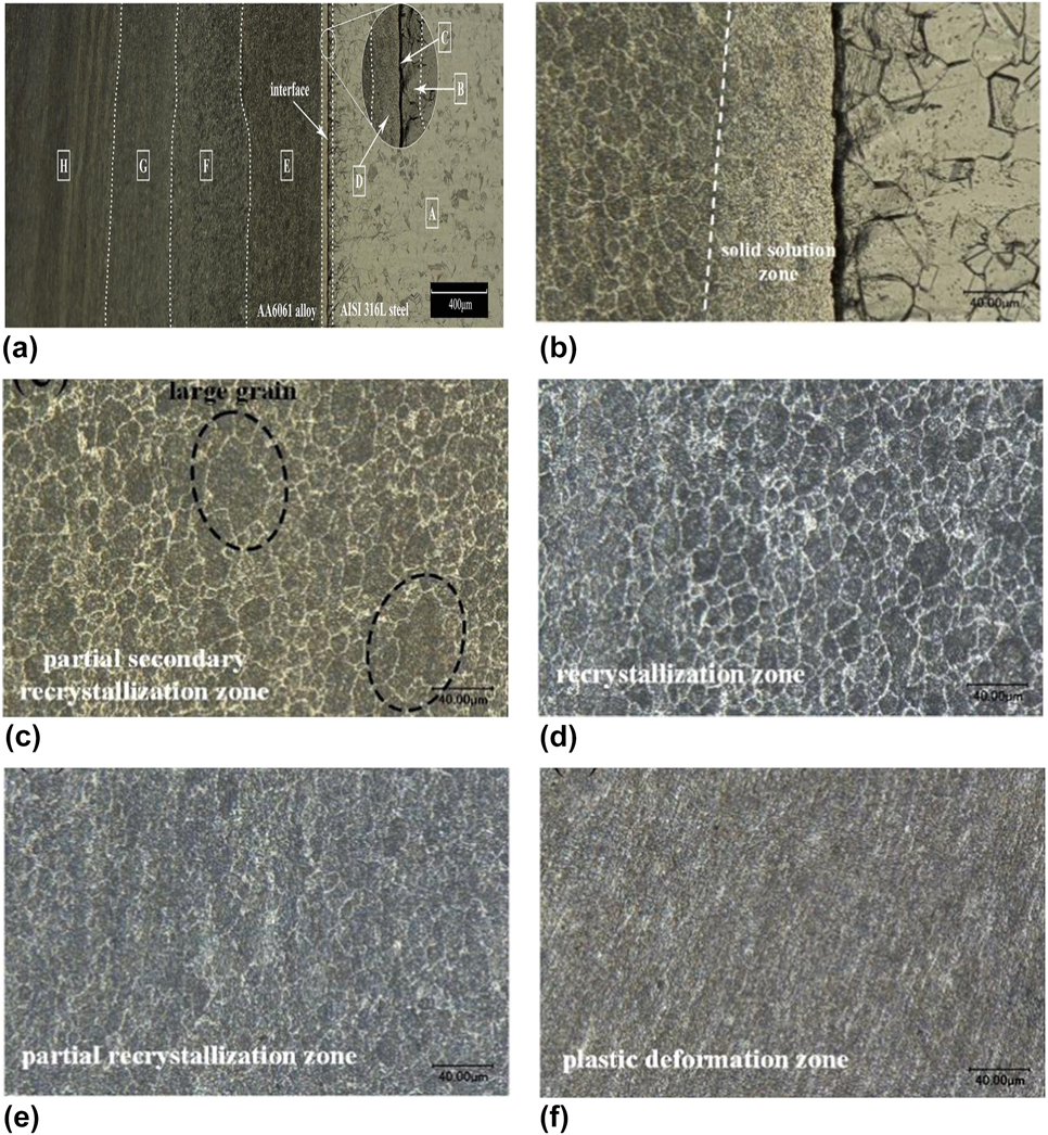
Region B of Fig. 3(a) indicates heat and deformation affected zone at the stainless steel side, which is generated due to frictional heat as well as plastic deformation. In this region, significantly smaller grains are reported with broadened crystal boundaries.Reference Taban, Gould and Lippold41,Reference Herbst, Aengeneyndt, Maier and Nürnberger45,Reference Reddy, Rao and Mohandas51,Reference Wan and Huang54 Despite this, no major microstructural changes are occurred at the stainless steel side. The most critical microstructure zone is the interface of Al–steel that consists of the layer of IMCs as maximum interactions between Al and steel occur at this region.Reference Taban, Gould and Lippold41–Reference Wan and Huang54 On the other hand, major microstructural changes are observed at the Al side, which are noticed as complex to define.Reference Taban, Gould and Lippold41,Reference Herbst, Aengeneyndt, Maier and Nürnberger45,Reference Reddy, Rao and Mohandas51,Reference Wan and Huang54 Figure 3(b) shows the solid solution region that is created due to insufficient precipitation caused by experiencing highest temperature and fast cooling rate. Figure 3(c) shows the partial secondary recrystallized zone, wherein the combined effect of plastic deformation and high temperature is resulted in refined and equiaxed grains along with few large size grains. Next to it, the equiaxed recrystallized zone can be seen from Fig. 3(d) that is caused due to adequate temperature for grain growth recovery. Figure 3(e) shows the partial recrystallization zone that is generated due to low temperature than the region of the recrystallized zone. Figure 3(f) shows the plastically deformed zone that is formed due to mechanical deformation of the Al material caused by inadequate frictional heat and heat input as it is far from the interface of Al–steel.Reference Wan and Huang54 Some of these four zones are referred as the thermomechanically affected zone (TMAZ) in some of the literature studies.Reference Taban, Gould and Lippold41,Reference Herbst, Aengeneyndt, Maier and Nürnberger45,Reference Reddy, Rao and Mohandas51,Reference Wan and Huang54 The less heat generation may result in less number of zones that subsequently treated as TMAZ based on material deformation and grain growth affected by heat input. For example, Wan et al.Reference Wan and Huang54 mentioned that the decrease in friction time reduces heat input, which in turn reduces the number of microstructural zones. Furthermore, the zones can be affected by only heat and that is treated as HAZ, if the mechanical deformation is not present.
The aforementioned microstructural features can be found for Al–steel friction welded joints without having any interlayer. The addition of the third material as the interlayer between Al–steel materials influences the microstructure of the interface along with the thickness of IMCs at the interface. In the case of Al–steel friction welding, without using any interlayer, brittle IMCs are formed while the interlayer material such as Ag generates IMC phases of Ag2Al and FeAl.Reference Reddy, Rao and Mohandas51 Other than Ag, interlayer materials such as Ni and Cu can be used as an option to improve the bonding between dissimilar materials Al–steel.Reference Reddy, Rao and Mohandas51 However, the formation of IMCs such as AlNi, Al3Ni AlNi, and Al3Ni for the Ni interlayer and formation of CuAl2, CuAl, Cu9Al4 CuAl2, and CuAl for the Cu interlayer are reported by Reddy et al.Reference Reddy, Rao and Mohandas51 The use of interlayer is considered as the unique parameter of dissimilar friction welding in addition to conventional process parameters.
The mechanical properties such as tensile strength, ductility, and hardness of dissimilar Al–steel friction welds are influenced by process parameters and working conditions. The tensile strength of dissimilar Al–steel joints is reported lower than the steel base material, considering the differences in the properties and complexity observed in microstructural features including IMCs. Acceptable tensile strength is considered as strength nearly equal to the Al-base material or more than that of Al. Controlled heat input through conventional process parameters of friction welding is recommended to obtain acceptable tensile strength. Sufficiently high axial pressure and lower deformation temperature through optimum friction time and relative speed can give better joint strength and ductility in the case of Al–steel friction welding. Literature studies suggested different ways such as the use of interlayer between Al–steelReference Reddy, Rao and Mohandas51 and contact surface modification,Reference Ashfaq, Sajja, Khalid Rafi and Prasad Rao47,Reference Wan and Huang54 to improve tensile strength of dissimilar Al–steel joints apart from conventional friction welding. Application of the interlayer of Ag between Al and steel provides improved tensile strength than the conventional friction welding from 20 to 270 Mpa.Reference Reddy, Rao and Mohandas51 It is also observed that the formation of IMC such as Fe2Al5 can be restricted by applying the Ag interlayer. On the other side, the Ag interlayer results in the formation of IMCs such as Ag2Al and FeAl that add ductility and subsequently improves hardness of the joint.Reference Reddy, Rao and Mohandas51 Another approach to improve mechanical properties through novel parameter is edge preparations.Reference Ashfaq, Sajja, Khalid Rafi and Prasad Rao47,Reference Wan and Huang54 The taper groove edge preparations of the steel material is recommended to improve joint strength relative to the conventional method of flat edge. The material flow and deformation pattern of joint area are significantly improved by this method of grove toward edge, which in turn resulted in enhancement of tensile strength. The improved intermixing by this method can result in improvement of the IMC layer.Reference Ashfaq, Sajja, Khalid Rafi and Prasad Rao47 The tensile specimens are prone to brake from the joint interface as IMCs are present at this region. In this case, the fracture surfaces reveal brittle fracture that is but obvious due to the formation of IMCs. However, optimum heat input results in braking of tensile specimens from the deformed zone of the Al base material.
III. FRICTION STIR WELDING
FSW is a variant of friction welding, invented at The Welding Institute (TWI) in 1991.Reference Mishra, Sarathi De and Kumar55,Reference Mehta and Gupta56 In the FSW process, the nonconsumable tool is applied to the surfaces of the workpieces to be joined as shown in Fig. 3. This nonconsumable tool consists of featured pin and shoulder, which is inserted into the workpiece until shoulder contacts the top surface of the workpiece. The rubbing action between tool surfaces and workpiece generates heat that in turn softens the material under tool shoulder. Following it, transverse movement of tool is given, which is responsible for the movement of the softened material from front to the trail of the tool.Reference Mehta and Badheka57 Upon cooling to room temperature, the recrystallized weld zone is obtained along with bonding between two workpieces. Axial pressure and tool tilt angle are used as process parameters that help to forge the material downward in the direction of tool axis to obtain full penetration equal to or more than pin length. Therefore, it can be noted that rotational speed, travel speed, axial force, tool tilt angle, and tool design are most important process parameters of the FSW process.Reference Mishra, Sarathi De and Kumar55,Reference Mehta and Gupta56 The major advantage of FSW over friction welding is joint configurations. Apart from butt joint configuration mentioned in Fig. 4, FSW can be applied for different configurations such as lap joint, overlap joint, T joint, and L joint.Reference Mishra, Sarathi De and Kumar55 Atomized spindle/robotic arm can be adopted in FSW, to follow complex contours that in turn provide welding of complex profiles.Reference Zappia, Corporation, Smith, Link, Colligan, Lohwasser and Chen58 Formation of exit-hole as a cavity of pin shape that is left at the end phase of the process is a major disadvantage of the process, which can be solved by advanced refilling techniques.Reference Mishra, Sarathi De and Kumar55,Reference Mehta and Gupta56,Reference Mishra and Mahoney59
Dissimilar FSW of steel to aluminum.
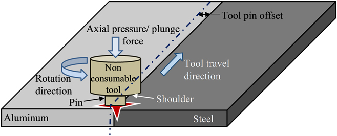
FSW can be applied to different dissimilar combinations such as Al–steel,Reference Shah and Ishak6 Al–Cu,Reference Mehta and Badheka60–Reference Mehta and Badheka63 Al–titanium,Reference Chen and Nakata64 Al–magnesium,Reference Shah, Othman and Gerlich65 magnesium–steel,Reference Chen and Nakata66 titanium–steel,Reference Fazel-Najafabadi, Kashani-Bozorg and Zarei-Hanzaki67 and polymers–metals.Reference Sengupta, Chakraborty, Bandyopadhyay, Dasgupta, Mukhopadhyay, Auddy and Deuri68 The FSW process is one of the maximum investigated processes for the dissimilar joints considering the number of articles available. In the case of dissimilar Al–steel, the FSW process is having additional parameters such as tool pin offset at Al side and placing of the steel material at advancing side (i.e., the place where rotation direction and transverse direction are same),Reference Shah and Ishak6 as shown in Fig. 4. Differences in properties can be adjusted with the help of these two new parameters. Pin offset in the Al material can be explained by the displacement of the tool to the Al base material, which is required because the deformation of both the materials cannot be attained at the same time of the operation. Pin offset in Al leads to major plastic deformation of the Al material while partial deformation of the steel material, which causes the dispersion of steel particles and that consequently lead to mixing of steel particles into the Al matrix.Reference Atabaki, Nikodinovski, Chenier, Ma, Harooni and Kovacevic1,Reference Bang, Bang, Jeon, Oh and Ro25,Reference Mishra, Sarathi De and Kumar55,Reference Watanabe, Takayama and Yanagisawa69–Reference Yazdipour and Heidarzadeh88 The size of these steel particles are dependent on tool pin offset majorly as well as heat input given by the process parameters of rotational speed, travel speed, and tool design. Another important parameter is the position of the workpiece,Reference Atabaki, Nikodinovski, Chenier, Ma, Harooni and Kovacevic1,Reference Shinoda, Miyahara, Ogawa and Endo53,Reference Derazkola, Elyasi and Hossienzadeh89,Reference Chen and Kovacevic90 wherein, effective material flow and enhanced mixing can be obtained when steel is kept at the advancing side and Al at the retreating side. The tool pin disperses steel particles from the advancing side and drops into the Al matrix in an effective way, considering the same direction of rotation speed and travel speed. In the case of lap joint configuration, Al is kept on the top of steel and tool pin is inserted full in Al and minor in steel. The nonconsumable tool is having important elements such as pin diameter/dimensions, pin shape feature, shoulder diameter, shoulder surface geometry, shoulder to pin diameter ratio, and pin length that need to be fixed in such a way that effective dissimilar joint of Al–steel can be obtained.Reference Hussein, Tahir and Hadzley3,Reference Mishra, Sarathi De and Kumar55,Reference Watanabe, Takayama and Yanagisawa69–Reference Elyasi, Derazkola and Hosseinzadeh75,Reference Abbasi, Dehghani, Guim and Kim77–Reference Dehghani, Amadeh and Akbari Mousavi81,Reference Kimapong and Watanabe85,Reference Dehghani, Mousavi and Amadeh87–Reference Yazdanian120 Shoulder diameter, its surface area, and shoulder to pin diameter ratio contribute maximum to the heat input that in turn influences joint formation. Pin dimensions and its features decide the material flow. The cylindrical pin is studied maximum for dissimilar Al–steel combinations as the dispersion of particles are more useful with the cylindrical pin in the case of dissimilar FSW.Reference Mehta and Badheka121 The ratio of rotational speed to travel speed is equally responsible for the heat input. The optimum ratio is recommended to perform the dissimilar FSW. The variation in thickness of the base material needs variable heat input according to dimensions that subsequently require change in tool design, rotational speed, and travel speed.
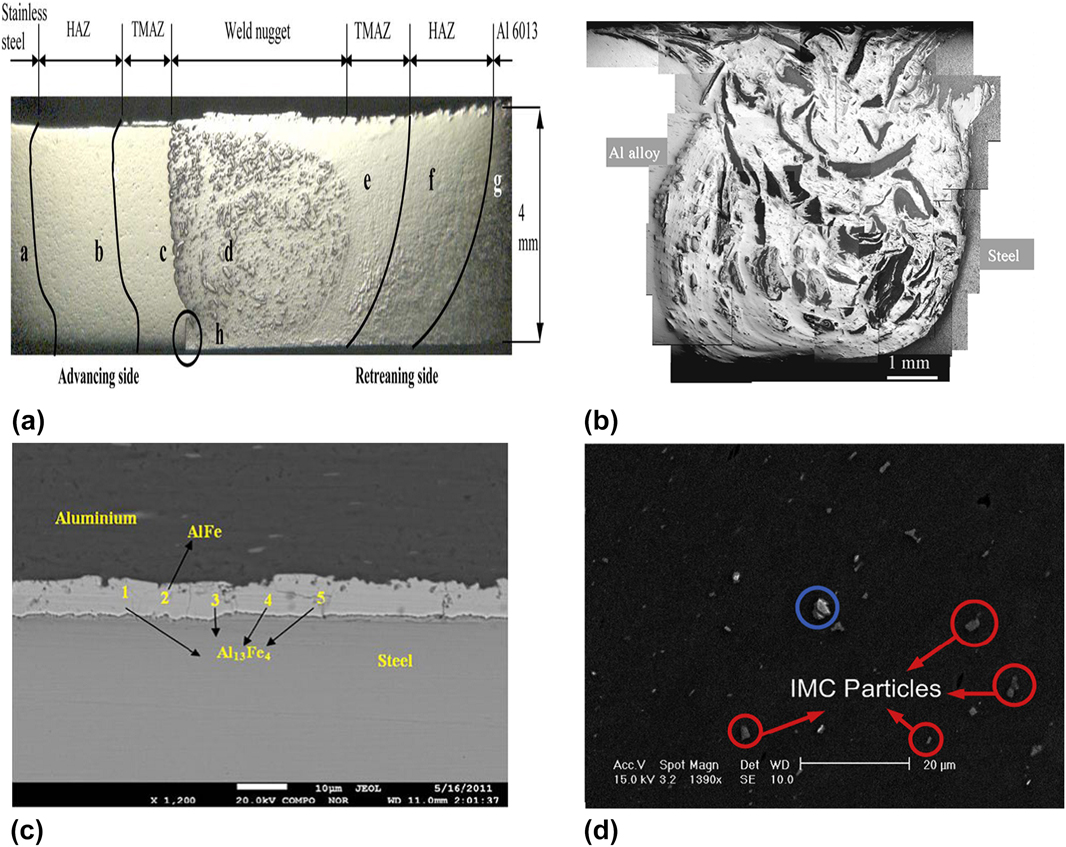
In terms of microstructure features, dissimilar FSW of Al–steel joints consists of distinct microstructural zones such as stir zone, TMAZ of Al, TMAZ of steel, HAZ of Al, and HAZ of steel in addition to base material microstructuresReference Hussein, Tahir and Hadzley3,Reference Shah and Ishak6,Reference Shinoda, Miyahara, Ogawa and Endo53,Reference Fazel-Najafabadi, Kashani-Bozorg and Zarei-Hanzaki67–Reference Yazdipour and Heidarzadeh73,Reference Elyasi, Derazkola and Hosseinzadeh75–Reference Coelho, Kostka, dos Santos and Kaysser-Pyzalla79,Reference Tang and Shen83,Reference Kimapong and Watanabe85–Reference Springer, Kostka, dos Santos and Raabe118,Reference Seo, Song and Park122 as shown in Fig. 5(a). The stir zone is an area, where bonding between steel and Al is taking place in FSW. Major plastic deformation of Al leads to recrystallized zone of its matrix wherein steel particles are mixed in a random manner. It is recommended to have uniform distribution of these steel particles in the Al matrix as shown in Fig. 5(b), to obtain enhanced mechanical properties and very less tool wear. However, the dispersion of steel particles should not be excessive. The size of steel particles dispersed from the steel material is recommended to as less as possible that helps in effective mixing with the Al matrix. The large-sized dispersed particles cause restriction in material flow and lead to the defects such as void, cavity, tunnel, and channel. As the stir zone consists of Al matrix and steel particles, it can be treated as the metal matrix composite zone. The stir zone interface with steel consists of the IMC layer while different phases of IMCs are also formed inside the stir zone. The presence of IMCs is reported in a layer form also around the steel particles [see Figs. 5(c) and 5(d)].Reference Abbasi, Dehghani, Guim and Kim77 Traveling of Fe particles from the steel workpiece also influences the formation of IMCs. The IMC phases of FeAl2, FeAl3, Al13Fe4, and Al5Fe2 are detected in different literature studies of Al–steel FSW.Reference Watanabe, Takayama and Yanagisawa69,Reference Ghosh, Gupta and Husain106,Reference Pourali, Abdollah-zadeh, Saeid and Kargar113,Reference Bozzi, Helbert-Etter, Baudin, Criqui and Kerbiguet123 The thickness of the IMC layer at the interface is reported in the range of <0.1 µm–58.1 µm.Reference Hussein, Tahir and Hadzley3,Reference Shah and Ishak6,Reference Shinoda, Miyahara, Ogawa and Endo53,Reference Fazel-Najafabadi, Kashani-Bozorg and Zarei-Hanzaki67–Reference Yazdipour and Heidarzadeh73,Reference Elyasi, Derazkola and Hosseinzadeh75–Reference Coelho, Kostka, dos Santos and Kaysser-Pyzalla79,Reference Tang and Shen83,Reference Kimapong and Watanabe85–Reference Springer, Kostka, dos Santos and Raabe118,Reference Seo, Song and Park122 Thickness of IMCs in the Al–steel FSW system is governed by shoulder diameter, shoulder to pin diameter ratio, rotational speed, and travel speed as heat input is largely influenced by these parameters. Rest of the parameters of FSW such as tool pin offset, material position, and axial pressure play significant role for the proportion of Al and steel interaction and hence IMCs are also influenced by them. Majority of literature studies related to Al–steel FSW have suggested that the IMC layer <5 µm can report better joint properties.Reference Hussein, Tahir and Hadzley3,Reference Shah and Ishak6,Reference Shinoda, Miyahara, Ogawa and Endo53,Reference Fazel-Najafabadi, Kashani-Bozorg and Zarei-Hanzaki67–Reference Yazdipour and Heidarzadeh73,Reference Elyasi, Derazkola and Hosseinzadeh75–Reference Coelho, Kostka, dos Santos and Kaysser-Pyzalla79,Reference Tang and Shen83,Reference Kimapong and Watanabe85–Reference Springer, Kostka, dos Santos and Raabe118,Reference Seo, Song and Park122 Larger thickness of IMCs always deteriorates the mechanical properties of the joint that is evidenced in the case of Al–steel FSW in number of articles.Reference Watanabe, Takayama and Yanagisawa69,Reference Ghosh, Gupta and Husain106,Reference Pourali, Abdollah-zadeh, Saeid and Kargar113,Reference Bozzi, Helbert-Etter, Baudin, Criqui and Kerbiguet123 The phases developed in the case of FSW are because of solid state diffusion with metal to metal interactions, interreaction with phases and lowest eutectic compositions, and inter reactions of phases and Fe.Reference Sengupta, Chakraborty, Bandyopadhyay, Dasgupta, Mukhopadhyay, Auddy and Deuri68,Reference Murugan, Thirunavukarasu, Kundu, Kailas and Chatterjee93,Reference Ghosh, Kar, Kumar and Kailas105,Reference Movahedi, Kokabi, Seyed Reihani, Cheng and Wang112,Reference Seo, Song and Park122 The stir zone consists of small size grain size of the Al–steel mixed material along with the presence of relatively large steel particles. On contrary to the increase in heat input via increase in rotational speed, the stirring effect is increased with an increase in rotational speed that further decreases the grain size of the stir zone to ultrafine grains, whereas the grain size becomes coarsen when heat input increases through reduction in travel speed and increase in shoulder diameter. TMAZ is a zone that is developed due to the effects of thermal and mechanical deformation under the shoulder of the tool. The grains of TMAZ are deformed and elongated due to stirring effects. The Al side is largely affected by TMAZ compared to the steel side and tool is displaced toward the Al side in the case of Al–steel FSW. HAZ is a zone that is adjacent to the TMAZ and no major changes of grain size are observed relative to the respective base material.Reference Uzun, Dalle Donne, Argagnotto, Ghidini and Gambaro103 However, some of the literature studies have reported increased grain size in HAZ relative to the base material due to thermal effects.Reference Coelho, Kostka, dos Santos and Kaysser-Pyzalla79
Microstructural features of Al–steel FSW joints, (a) different zones indicated, with permission from Ref. Reference Uzun, Dalle Donne, Argagnotto, Ghidini and Gambaro103, (b) complex stir zone, with permission from Ref. Reference Jiang and Kovacevic102, (c) Al–steel interface with IMC layer, with permission from Ref. Reference Das, Basak, Das and Pal107, and (d) presence of IMCs in the stir zone, with permission from Ref. Reference Liu, Lan and Ni78.
In the case of lap joint configuration, the stir zone consists of different microstructural behaviors than butt joint configurations as workpiece materials are lapped. In the case of lap joint, the Al is kept upward to the steel base material and hence the stir zone behaves like dynamically recrystallized zone with ultrafine grains majorly in Al. The interface zone of Al–steel is identified as metal matrix zone, where the dynamically recrystallized micro-structure is reported. Ultrafine grain size is generally reported at this stirred area due to large mechanical deformation and recrystallization. In addition to this, steel fragments are distributed in the Al matrix similar like butt joint configuration. However, in the case of lap joint configurations, the distribution of steel fragments is horizontal in direction that is different than the butt joint configuration. IMCs are presented in a direction of horizontal along the base material interaction surfaces. TMAZ and HAZ are formed like conventional FSW of similar materials. However, variations of zones are reported in the vertical direction as the dissimilar materials consist of variation properties.
Mechanical properties such as tensile properties and hardness are studied in majority of the literature studies.Reference Hussein, Tahir and Hadzley3,Reference Shah and Ishak6,Reference Shinoda, Miyahara, Ogawa and Endo53,Reference Fazel-Najafabadi, Kashani-Bozorg and Zarei-Hanzaki67–Reference Yazdipour and Heidarzadeh73,Reference Elyasi, Derazkola and Hosseinzadeh75–Reference Coelho, Kostka, dos Santos and Kaysser-Pyzalla79,Reference Tang and Shen83,Reference Kimapong and Watanabe85–Reference Springer, Kostka, dos Santos and Raabe118,Reference Seo, Song and Park122 These properties are greatly influenced by the mixing of Al and Fe fragments that is governed by FSW process parameters. High heat input conditions such as too low travel speed, very high rotational speed, and large shoulder diameter cause more material deformation that in turn detaches large fragments of Fe particles, which is difficult to mix with the Al matrix and results into the defects (such as voids and cracks).Reference Hussein, Tahir and Hadzley3,Reference Mahto, Bhoje, Pal, Joshi and Das70,Reference Shen, Chen, Haghshenas and Gerlich92,Reference Das, Kumar, Rajkumar, Saravanan, Jayakumar and Pal99,Reference Movahedi, Kokabi, Reihani and Najafi111 Voids and cracks are generated due to improper material flow caused due to large fragments of Fe particles. These defects subsequently reduce the tensile strength of the stir zone. Aside from high heat input conditions, less tool pin offset and wrong placement of workpiece material lead to large dispersion of Fe fragments that in turn generate same conditions of voids and cracks and subsequently reduces the tensile strength.Reference Watanabe, Takayama and Yanagisawa69,Reference Sadeghian, Taherizadeh and Atapour72–Reference Elyasi, Derazkola and Hosseinzadeh75,Reference Yazdipour and Heidarzadeh88 Furthermore, higher heat input forms large amount of IMCs in the stir zone and makes it hard, brittle, and low strength zone. These IMCs cause major variations in the hardness at the stir zone, Al base material, and steel particles along with distinct microstructures. Hardness peak values are reported in different literature studies such as 350 HV,Reference Shen, Chen, Haghshenas and Gerlich92 500 HV,Reference Ramachandran, Murugan and Shashi Kumar74 400 HV,Reference Chen and Kovacevic90 739 HV,Reference Das, Ghosh and Pal98 376 HV,Reference Elrefaey, Gouda, Takahashi and Ikeuchi100 320 HV,Reference Jiang and Kovacevic102 250 HV,Reference Uzun, Dalle Donne, Argagnotto, Ghidini and Gambaro103 335 HV,Reference Movahedi, Kokabi, Reihani and Najafi111 350 HV,Reference Ramachandran, Murugan and Shashi Kumar74 and 270 HV.Reference Yazdipour and Heidarzadeh73 These differences are because of variations in IMCs in volume fractions. The thick layer of IMCs at the interface between stir zone and steel material is observed in the case of high heat input conditions that are consequently responsible for the brittle fracture of tensile specimens. Besides, insufficient material deformation is caused by low heat input conditions such as very high travel speed, low rotational speed, and small shoulder diameter. The defects such as tunnel, voids, and lack of fill are generated due to nonuniform material flow caused by insufficient material deformation. Therefore, optimum combination of process parameters is required to obtain better mechanical properties. However, the tensile strength of the stir zone is always less than or equal to the Al base material due to the dissimilarities in properties of both the materials of Al and steel.
The FSW process is expanded with different approaches such as application of Zn interlayer between Al and steel base material,Reference Zheng, Feng, Shen, Huang and Zhao71 scroll tool shoulder without pin,Reference Ibrahim, Uematsu, Kakiuchi, Tozaki and Mizutani91 wave shape tool pin base for lap joint configurations,Reference Sorger, Wang, Vilaça and Santos117 kneed type butt joint configuration,Reference Geiger, Micari, Merklein, Fratini, Contorno, Giera and Staud124 and cutting edge type tool pin.Reference Xiong, Li, Qian, Zhang and Huang80 It is recommended to use third material layer as the interlayer between dissimilar materials in the case of FSW. The joint properties of Al–steel dissimilar welds can be enhanced by putting the thin Zn interlayer between base materials. The Zn interlayer enhances the formation of IMCs that in turn improves the strength of the joint while reduces hardness and brittleness of the joint.Reference Zheng, Feng, Shen, Huang and Zhao71 Wave shaped tool pin base has improved steel flow in the Al material with two passes of processing.Reference Sorger, Wang, Vilaça and Santos117 However, obtained tensile strength from wave shaped tool pin base is not up to the mark relative to the conventional method. Cutting edge type of the tool is adopted to obtain enhanced distribution of steel particles in Al that in turn resulted into higher strength than the Al base material. This method is not so popular due to complex tool design and sticking of the base material on that complex tool.
IV. HYBRID FRICTION STIR WELDING
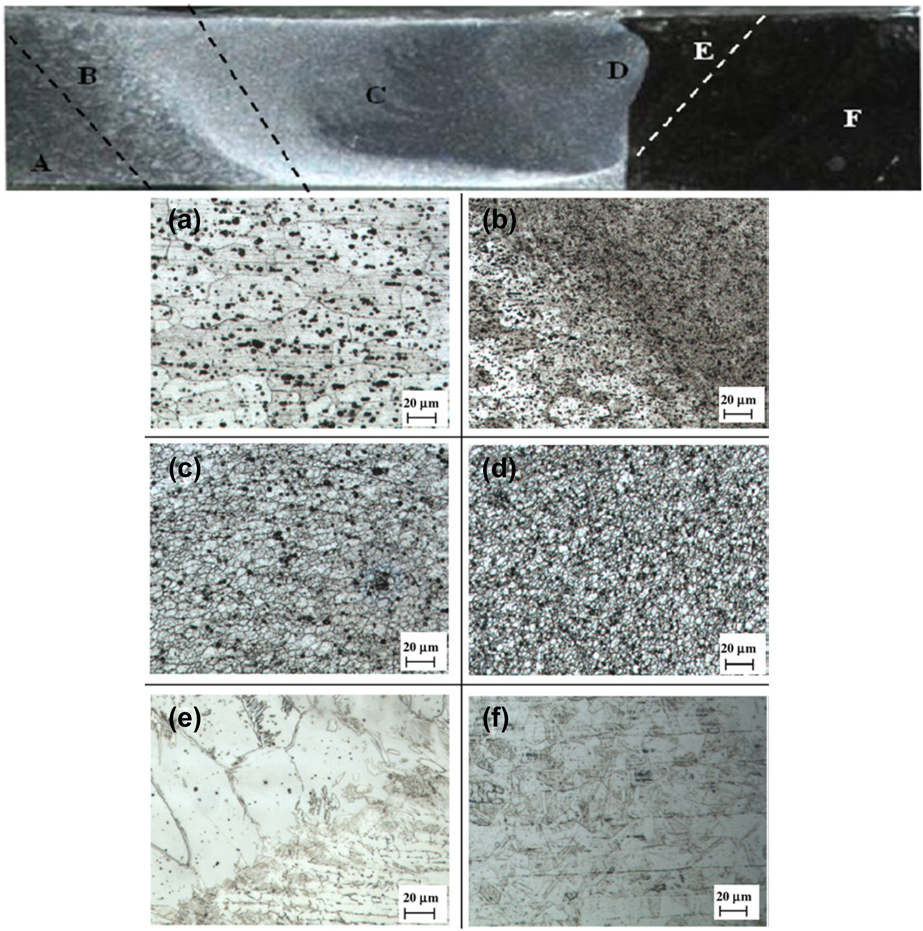
HFSW can be interpreted as a combination of conventional FSW with another process. Combination of two processes can enhance the capability of the conventional manufacturing process. Dissimilar Al–steel joints are benefitted by HFSW as the differences in deformation behavior of both the materials can be managed by secondary heat source. Secondary heat source can be applied to the particular base material that helps in enhancing bonding between base materials. HFSW techniques such as GTAW-assisted FSW, laser-assisted FSW, arc-assisted FSW, and electrically assisted FSW. Bang et al.Reference Bang, Bang, Jeon, Oh and Ro25 studied GTAW-assisted FSW for dissimilar AA6061-T6 to 304 stainless steel through preheating effect applied on the stainless steel base material (at 2 mm away from the center line). The preheating of stainless steel can ensure tool wear reduction and subsequently enhances the material flow through increased deformation behavior of stainless steel. Tensile strength and ductility of the joint can be enhanced with GTAW-assisted FSW. This approach causes finer grains in HAZ and TMAZ of the Al side relative to the stir zone as can be seen from Fig. 6. Similar stir zone of the Al material with steel particles is observed in GTAW-assisted FSW. However, severe plastic deformation and higher temperature attribute to slightly finer recrystallized grains in the stir zone compare to the stir zone of conventional FSW.
Microstructural changes of dissimilar Al-steel GTAW assisted FSW joint: (a) Al base material, (b) TMAZ of Al side, (c) stir zone, (d, e) stir zone-steel interface-TMAZ of steel side, and (f) steel base material, with permission from Ref. Reference Bang, Bang, Jeon, Oh and Ro25.
Laser-assisted FSW is investigated by Fei et al.Reference Fei, Jin, Ye, Xiu and Yang76,Reference Fei, Jin, Peng, Ye, Wu and Dai125 for Al–steel dissimilar joint, wherein laser is applied as preheating source on the steel base material small distance away from the joint line similar like GTAW-assisted FSW. It is always suggested with different heating assisted FSW approaches that the tool wear can be significantly reduced and travel speed can be increased. The stir zone of laser-assisted FSW is again like Fe particles mixed with the Al matrix without major changes in other zones. However, it is suggested that additional parameters enhance the microstructures and mechanical properties of the joints. It is suggested to keep predrill at the Al side while performing laser-assisted FSW to improve plunge phase and subsequent material flow. Due to the predrill factor, the layer of IMCs at that particular location is enhanced and consequently tensile strength is improved.Reference Fei, Jin, Ye, Xiu and Yang76 Another additional factor of laser-assisted FSW for Al–steel joint is filler material addition. Foil of the Ni material is recommended for Al–steel laser-assisted FSW joint that augments the tensile strength of the joint as well as the ductility of the joint. On the other hand, Zn foil reduces the strength and increases the brittleness of the joint. The use of the Ni interlayer between Al and steel material is also mentioned in the section of friction welding as it improves mechanical properties by having better metallurgy. Besides, the Zn interlayer is recommended in the case of previous section of conventional FSW, where brittleness and increase in hardness are the issues observed in line with hybrid FSW due to the formation of brittle IMCs. Electrically assisted FSW is a technique in which electrical resistance is applied as a preheating source that leads to effective electroplastic effect and enhances the formation of IMCs with improved micro interlock features at the stir zone that in turn improves the quality of joint.Reference Liu, Lan and Ni86 In the case of heating assisted FSW, process parameters such as distance between heating source to the FSW tool, angle and distance of heating source from the joint line, amount of heat supplied via heating source, and type of heating source used are the extra factors in addition to process parameters of FSW that are required to be considered. Preheating of steel leads to partial annealing effect and helps to soften the steel material at that particular location, which subsequently improves material flow and results in better joint properties.
V. FRICTION STIR SPOT WELDING
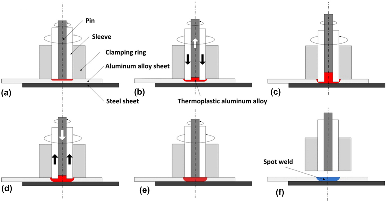
FSSW is developed from the process principle of FSW, which uses to make spot welds.Reference Kallee, Lohwasser and Chen126 The travel phase of the FSW process is completely eliminated in this process while the dwell phase is considered as an important phase of the FSSW process. Automobile structures of dissimilar Al–steel joints are applied with FSSW due to benefits over other spot welding processes. FSSW is an alternative method of resistance spot welding and mechanical fastening. FSSW is applied majorly in the case of lap joint configuration. Process parameters such as tool design, rotational speed, dwell time, depth of plunging, rate of plunging, and position of the workpiece material are considered as important as far as dissimilar Al–steel FSSW is concerned.Reference Chen, Liu and Ni82,Reference Ibrahim, Uematsu, Kakiuchi, Tozaki and Mizutani91,Reference Bozzi, Helbert-Etter, Baudin, Criqui and Kerbiguet123,Reference Dong, Chen, Song, Guo, Zhang and Sun127–Reference Uematsu, Kakiuchi, Tozaki and Kojin143 Application of fixture is also considered as an important parameter when the joint configuration is complex. Double sided FSSW is developed for dissimilar Al–steel joints with special purpose fixture by Lyu et al.Reference Lyu, Li, Li and Chen131 The heat input is majorly governed by tool diameter, rotational speed, and dwell time that subsequently affect the formation of IMCs. Besides, the material flow and mixing is highly dependent on penetrating depth and position of the workpiece material in lap configuration.Reference Piccini and Svoboda138 The microstructural changes of FSSW are similar to the FSW process such as stir zone, TMAZ, and HAZ, as frictional heat softens the base material and subsequent recrystallization leads to joint formation.Reference Fei, Jin, Peng, Ye, Wu and Dai125–Reference Sun, Fujii, Takaki and Okitsu141 In the case of dissimilar Al–steel FSSW, the Al base material is suggested to keep on top of the steel base material as it is a soft material that subsequently leads to better plunge phase and recrystallized grain formation in the stir zone with particles of steel dispersion. By keeping Al on top of steel, the forces required for the plunge stage and tool wear are less. Moreover, the depth of the penetration of tool pin controls the dispersion of steel fragments. Smaller depth leads to fine dispersion and better mixing while higher depth results in large dispersion and generates defects. Besides, the zero penetration depth, i.e., tool pin penetration in the Al base material up to full thickness without penetrating into the steel base material is not recommended due to poor strength and joining mechanism. Solid state diffusion causes metallurgical bonding and forms IMCs at the interface between Al and steel in the case of FSSW without pin penetration in steel, whereas in addition to IMC formation, mechanical hooking and swirl layered microscopic mechanical lock effects improve the strengthening of Al–steel dissimilar joint.Reference Fereiduni, Movahedi and Kokabi133 However, mechanical interlocking by the hocking effect is not advantageous when the hooking effect is large. Therefore, selection of pin length is critical. Generally, pin length is kept slightly higher than the thickness of the Al base material. Due to variations in properties of both the base materials, TMAZ, HAZ, and stir zone consist of different types of grains on both the sides of them. The deformation is high at the Al side and hence large TMAZ and HAZ are formed at the Al side.Reference Ghosh, Gupta and Husain106,Reference Fereiduni, Movahedi and Kokabi129,Reference Chen, Liu and Ni132,Reference Fereiduni, Movahedi and Kokabi133,Reference Piccini and Svoboda138 At the end of FSSW, the exit-hole formation is again occurred at the stir zone, which is resolved with the development of refilling techniques or pin less FSSW techniques.Reference Mishra and Mahoney59,Reference Mehta and Badheka63,Reference Chen, Liu and Ni82,Reference Ding, Shen and Gerlich130,Reference Shen, Chen, Ding, Hou, Shalchi Amirkhiz, Chan and Gerlich140 Scrolled shoulder tool of without pin is found as one of the methods to eliminate the exit-hole effect with improved material flow.Reference Ibrahim, Uematsu, Kakiuchi, Tozaki and Mizutani91 However, cavity formation is always there with these types of techniques. Refill FSSW is a popular technique to obtain the exit-hole free stir zone in the case of dissimilar Al–steel joints (refer Fig. 7). Refill FSSW results in improved joint strength with improved material flow in the stir zone area.Reference Dong, Chen, Song, Guo, Zhang and Sun127 Vertical movement of the pin with additional pressure by sleeves fills the cavity formed during the FSSW process as shown in Fig. 7 that subsequently improves the microstructures of the stir zone and surroundings when compared with conventional FSSW. It is observed that dispersion of steel particles is significantly improved with refill FSSW. The formation of IMCs is observed in a layer form as mentioned in previous sections of different welding processes. A continuous layer of IMCs with its minimum thickness at the interface of Al–steel joints is recommended.Reference Mishra and Mahoney59,Reference Mehta and Badheka63,Reference Chen, Liu and Ni82,Reference Ding, Shen and Gerlich130,Reference Shen, Chen, Ding, Hou, Shalchi Amirkhiz, Chan and Gerlich140 The presence of brittle IMCs at the interface of Al–steel results in brittle fracture during shear testing. These brittle IMCs are responsible for having very high hardness at the joint interface as similar as mentioned in the case of FSW. Joint strength is considered better if it goes close to the Al base material with fracture from the Al base material. The exit-hole refilling by circular moving friction stir processing at the periphery of the exit-hole can also fill the cavity.Reference Chen, Liu and Ni82 However, this is not an effective one relative to refill FSSW, as another exit-hole by secondary process causes same difficulties.
Refill FSSW (a) before plunge, (b) plunge phase, (c) dwell phase, (d) refilling phase, (e) trim phase, and (f) retreating phase, with permission from Ref. Reference Dong, Chen, Song, Guo, Zhang and Sun127.
VI. FRICTION STIR SCRIBE WELDING
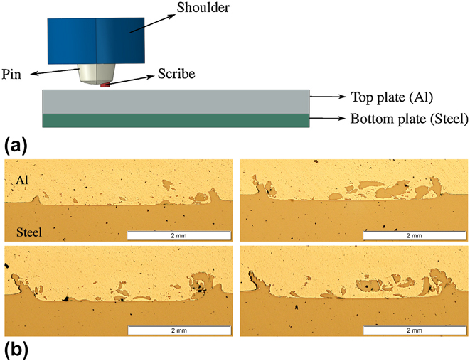
Friction stir scribe welding is a technique developed based on FSW that uses modified tool design to joint workpieces of lap joint configuration. The end surface of the tool pin consists of scribe that is hard material insert with very small lengthReference Wang, Sidhar, Mishra, Hovanski, Upadhyay and Carlson84,Reference Gupta, Upadhyay, Fifield, Roosendaal, Sun, Nelaturu and Carlson144 as shown in Fig. 8(a). This friction stir scribe welding technique is known as the hybrid combination of mechanical fastening and solid state joining. Dissimilar joint can be successfully obtained with friction stir scribe welding by inserting the tool pin into the low melting softer material (i.e., kept at top) along with scribe insertion in another material.Reference Wang, Sidhar, Mishra, Hovanski, Upadhyay and Carlson84,Reference Gupta, Upadhyay, Fifield, Roosendaal, Sun, Nelaturu and Carlson144 This causes huge plastic deformation at the pin area of the softer material and helps in dispersion of small particles from the bottom material and improves material mixing [see Fig. 8(b)]. This in turn forms hook-like interface with enhanced mechanical interlocking. The height of this hook is very important to govern mechanical properties such as joint strength.Reference Wang, Sidhar, Mishra, Hovanski, Upadhyay and Carlson84,Reference Gupta, Upadhyay, Fifield, Roosendaal, Sun, Nelaturu and Carlson144 Important process parameters of friction stir scribe welding are tool design including scribe design, rotational speed, travel speed, tool tilt angle, and plunge depth that influence dissimilar joint properties. The scribe length is kept very small that helps in removing small particles of the hard material, which improves material mixing as also mentioned in previous sections. It can be suggested to keep 0.5 mm or less than that as scribe length while tool pin length is to be kept near to the Al base material or slightly higher than that considering plunge depth.Reference Wang, Sidhar, Mishra, Hovanski, Upadhyay and Carlson84,Reference Gupta, Upadhyay, Fifield, Roosendaal, Sun, Nelaturu and Carlson144 However, the thickness of the workpiece is an important factor to decide scribe length and other tool dimensions. Formation of IMCs cannot be avoided with friction stir scribe welding of Al–steel joints. Similar IMC phases mentioned in the case of FSW are expected to form in this technique.Reference Wang, Sidhar, Mishra, Hovanski, Upadhyay and Carlson84,Reference Gupta, Upadhyay, Fifield, Roosendaal, Sun, Nelaturu and Carlson144 However, dispersion of steel particles is different in this case that may affect volume fraction of IMC formation. Figure 8(b) shows that the dispersion of steel fragments is varied along the length of the weld. Therefore, IMCs are proposed as different in volume fraction along the length as well. In the case of galvanized steel to Al alloy friction stir scribe welding, formation of Al–Zn solid solution is noted in addition to expected IMCs of the Al–steel binary system.Reference Uematsu, Kakiuchi, Tozaki and Kojin143
(a) Friction stir scribe welding and (b) material mixing from friction stir scribe welding along the length, with permission from Ref. Reference Gupta, Upadhyay, Fifield, Roosendaal, Sun, Nelaturu and Carlson144.
VII. FRICTION STIR BRAZING
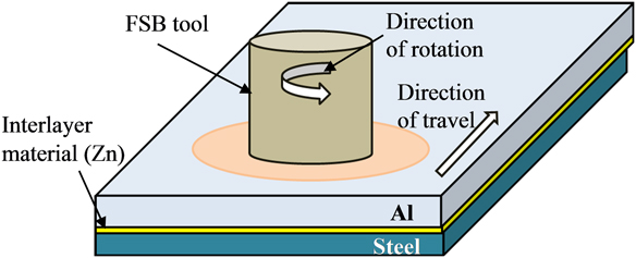
FSB is again developed from the FSW process with an application of the third material as an interlayer between base materials of lap joint configuration.Reference Zhang, Zhang, Guo and Zhang145,Reference Zhang, Su, Zhang and Wei146 FSB is a process in which the pinless tool consists of shoulder applied on the Al workpiece surface that is kept on the top of the fixture. Besides, steel is kept at the most bottom side of the fixture while the interlayer material is applied in between Al and steel. The Zn material is applied as an interlayer material by Zhang et al.Reference Zhang, Su, Zhang and Wei146 Refer Fig. 9 for FSB of the dissimilar Al–steel system. Multipasses are carried out to generate more amount of heat in the case of FSB. Process parameters such as rotational speed, travel speed, tool shoulder diameter, thickness of the interlayer material, and workpieces are considered important for Al–steel.Reference Zhang, Su, Zhang and Wei146
Friction stir brazing of Al–steel.
As the tool pin is not present in the case of FSB,Reference Zhang, Zhang, Guo and Zhang145,Reference Zhang, Su, Zhang and Wei146 the microstructural variations are different compared to FSW and other FSW-based processes. Plastic deformation in stir zone and other features like dispersion of steel fragments/particles and hook type mechanical interlocking are avoided in the case of FSB. To have the reaction of Al–Zn and Zn–steel interfaces, frictional heat generated via rubbing action between shoulder and workpiece is transferred to the interface between Al–Zn–steel, which in turn melts the interlayer material of Zn and leads to the reactions. These reactions are caused due to interdiffusion and form a variety of IMCs and eutectics based on the Zn–Al–Fe ternary alloy. Different phases of FeAl3(Zn) at Al side, Fe2Al5(Zn) at steel side, and eutectics of the Zn–Al super saturated structure are observed in FSB along with the presence of FeAl(Zn), and Fe2Al9(Zn) due to interdiffusion and Al dissolution in the molten Zn phenomenon.Reference Zhang, Su, Zhang and Wei146 Mentioned IMCs are reported in a layer form and the thickness of it varies from 25 to 3 µm.Reference Zhang, Su, Zhang and Wei146 Continuous thickness of these IMCs is recommended for good quality joint with its minimum possible value. Better shear tensile strength can be obtained when the thickness of IMCs is reported less, which is governed by process parameters. In the case of FSB, the workpiece thickness may be the constraint as the heat produced on the top surface must be transferred to the interface of Al–Zn–steel.
VIII. FRICTION MELT BONDING
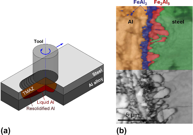
FMB is a process to join Al–steel dissimilar materials in lap configuration with pin less shoulder as like FSB but without using the interlayer material.Reference Van Der Rest, Jacques and Simar147 In addition to this, the steel material is positioned above the Al base material as shown in Fig. 10(a), unlike FSB and FSSW. Frictional heat is generated from the tool and transferred to the interface of Al–steel, which leads solid state plastic deformation that subsequently increases the temperature. Transfer of this heat to the Al base material leads to partial melting of it as that has lower melting point. This partial melting of Al forms localized pool at the contact interface as shown in Fig. 10(a), while the bottom part of Al remains in the solid state. Reaction of this localized melted Al and plasticized steel leads to joint formation.Reference Van Der Rest, Jacques and Simar147 Process parameters such as rotational speed, travel speed, shoulder diameters, tool tilt angle, and workpiece thicknesses are important to consider. In the case of thicknesses, FMB is recommended for low thickness workpieces. Besides, workpiece materials of larger thicknesses cannot be joined due to problems in heat availability at the interface between Al–steel. Rest et al.Reference Van Der Rest, Jacques and Simar147 performed successful experiments on 0.8 mm steel and 2 mm Al alloy to obtain dissimilar joint by FMB. Microstructural variations of FMB are TMAZ, reactive layer consists of IMCs, and dendritic structure at solidified Al. Formation of IMCs in different layer forms are reported at the interface that can be confirmed by Fig. 10(b), and IMC phases such as FeAl3 at Al side and Fe2Al5 at steel side are formed during the FMB process.Reference Van Der Rest, Jacques and Simar147 Better tensile strength can be obtained with FMB for Al–steel joints after performing postweld heat treatment processes.
Friction melt bonding (a) process principle and (b) formation of IMC-EBSD image, with permission from Ref. Reference Van Der Rest, Jacques and Simar147.
IX. FRICTION STIR SPOT FUSION WELDING
FSSFW is a derived technique of FSSW for lap joint configuration, wherein hollow shouldered tool having an assembly embedded rod in it. FSSFW is a process in which the steel material is kept on the Al base material and special tool is inserted into it.Reference Hsieh, Lee and Chiou148 The embedded rod in the hollow shouldered tool is used to avoid adhesion between shoulder surfaces and workpiece top surface after welding by moving it toward the end surface of the cylinder. Process parameters such as tool shoulder diameter, shoulder hollow diameter, rotational speed, dwell time, downward force, displacement after shoulder surface contacts the workpiece, and workpiece thicknesses are to be considered in the case of FSSFW.Reference Hsieh, Lee and Chiou148 As mentioned in Sec. VIII, partial melting of Al can be achieved when frictional heat is transferred from the top surface of steel to Al that is kept below the steel. Similarly, the partial melting of Al is obtained, which is responsible for the bonding with the interdiffusion phenomenon. Formation of the IMC layer with phases of Fe2Al5 and Fe4Al13 is noted when low carbon steel is welded to the Al alloy of 6061-T6.Reference Hsieh, Lee and Chiou148 Microstructural variations of FSSFW of Al–steel joint suggest that the layer of IMCs is thicker in the case of fusion zone relative to the deformation zone due to the strong interdiffusion phenomenon at the fusion zone. Appropriate range of IMCs thickness such as 6–17 μm is suggested to enhance failure load during shear tensile testing.Reference Hsieh, Lee and Chiou148 The material mixing and microstructural changes are suggested to be largely influenced by the thickness of the Al base material.
X. FRICTION STIR ASSISTED DIFFUSION WELDING
FSADW is a process promoted by the FSW process that is applied to lap joint configuration of Al–steel dissimilar joint, wherein Al is kept on top of steel.Reference Haghshenas, Abdel-Gwad, Omran, Gökçe, Sahraeinejad and Gerlich149 The tool used in FSW is used in the case of FSADW that consists of tool pin and shoulder with a difference of pin length. The pin length is kept slightly less (such as 0.2 mm) than the thickness of the Al base material to avoid contact with the steel base material.Reference Haghshenas, Abdel-Gwad, Omran, Gökçe, Sahraeinejad and Gerlich149 Therefore, the stirring action is intended to transfer heat at the interface of Al–steel, which consequently causes diffusion at the interface. Microstructures of FSADW suggest the recrystallized stir zone and TMAZ in the Al material while the diffusive interlayer of IMCs can be reported at the interface of Al–steel.Reference Haghshenas, Abdel-Gwad, Omran, Gökçe, Sahraeinejad and Gerlich149 IMC phases such as Al5Fe2 and AlFe are reported due to solid state diffusive action through intense deformation of thermomechanical processing imposed by friction as well as mechanical stirring action. The change in transverse speed affects heat input and subsequently influences the formation of IMCs. It is observed by Haghshenas et al.Reference Haghshenas, Abdel-Gwad, Omran, Gökçe, Sahraeinejad and Gerlich149 that IMC transformation from Al5Fe2 to AlFe is reported with the change in transverse speed from higher to lower.
XI. FRICTION STIR EXTRUSION
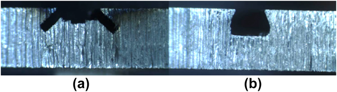
FSE is another friction-based joining technique applied to lap joint configuration of dissimilar Al–steel joints. The steel base material is kept below to the Al base material with special preparation such as slit saw grove and o ring dovetail groveReference Evans, Gibson, Reynolds, Strauss and Cook150 as shown in Fig. 11. The FSE tool is similar to FSW tool, inserted into Al base material up to the prepared grove area at the side of steel material, and hence the penetration length of tool is certainly higher than the thickness of Al base material. However, the contact of tool pin with steel is totally avoided with minor insertion in grove design on the steel material.Reference Evans, Gibson, Reynolds, Strauss and Cook150 The tool wear is drastically reduced as the pin is only stirring into the Al base material, which is easy to deform Al relative to the steel base material. Besides, the mixing of both the materials is not like mentioned in FSW. In the case of FSE, the Al base material is plastically deformed due to frictional heat produced. This solid state plastically deformed material is extruded to the steel grove that creates mechanical fixing of Al with steel along with diffusion bonding. However, the formation of IMCs is not reported with this type of manufacturing process that shows strong mechanical interlock between Al and steel with prepared grove. Out of two mentioned groves, slit saw grove has given better shear tensile strength relative to o ring dovetail grove.Reference Evans, Gibson, Reynolds, Strauss and Cook150
Friction stir extrusion edge preparation (a) slit saw grove and (b) o ring dovetail grove, with permission from Ref. Reference Evans, Gibson, Reynolds, Strauss and Cook150.
Same concept of FSE is utilized to obtain double sided bonding for Al–steel–Al base materials, which is named as two-sided friction stir riveting by extrusion.Reference Evans, Cox, Gibson, Strauss and Cook151 This technique is performed with the pin less tool with considered grove as the distance between two different steel plates in a sandwich structure of the Al–steel–Al base material. Two same tools are applied to the aforementioned base material from both the sides that in turn forms joint as mentioned above in FSE.Reference Evans, Gibson, Reynolds, Strauss and Cook150 Plastically deformed Al fills the cavity mentioned between two different steel plates, which subsequently joined with mechanical fixation.Reference Evans, Cox, Gibson, Strauss and Cook151 Therefore, authors of Ref. Reference Evans, Cox, Gibson, Strauss and Cook151 have given name as friction stir riveting by extrusion.
XII. FRICTION STIR DOVETAILING
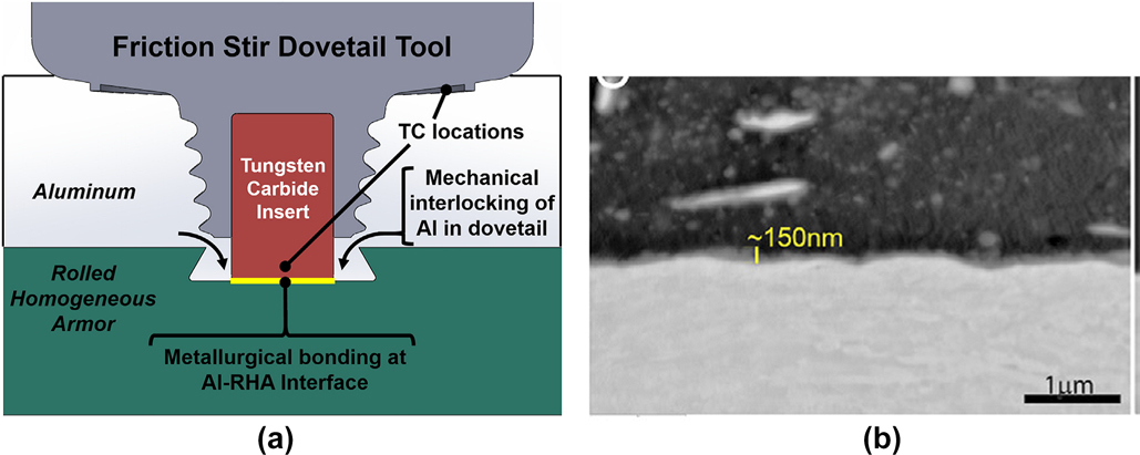
FSD is a technique to join dissimilar Al–steel joints in a lap joint configuration for thick sections. Figure 12(a) shows the process description of FSD wherein 12.7 mm sectional thick workpieces of Al–steel are joined.Reference Reza-E-Rabby, Ross, Overman, Olszta, McDonnell and Whalen152 A dovetail edge preparation is carried out before welding. The specially designed tool as shown in Fig. 12(a) is inserted into this dovetail groves up to the steel surface where tungsten carbide insert makes contact. This special edge preparation and tool design is able to obtain sound weld having mechanical interlocking along with strong metallurgical bonding.Reference Reza-E-Rabby, Ross, Overman, Olszta, McDonnell and Whalen152 The formation of the IMC layer is suppressed with the help of FSD technique based on localized solid state deformational bonding. The submicrolevel IMC layer can be observed in Fig. 12(b) which is formed after excellent metallurgical bonding obtained by the FSD process. The thickness of the IMC interlayer is identified through high magnification microscopy as low as in the range of 40–150 nm in the case of FSD.Reference Reza-E-Rabby, Ross, Overman, Olszta, McDonnell and Whalen152 The presence of FeAl3 IMCs is observed during FSD while other phases of the Al–Fe binary diagram are not reported.Reference Reza-E-Rabby, Ross, Overman, Olszta, McDonnell and Whalen152 It is suggested that FSD can help to obtain dissimilar Al–steel joint with superior lap shear strength relative to other friction stirred based processes.Reference Reza-E-Rabby, Ross, Overman, Olszta, McDonnell and Whalen152 Major microstructural differences can be expected in the Al base material relative to the steel material as full pin is inside Al while not making significant contact to the steel base material.
Friction stir dovetailing (a) process description and (b) SEM image of joint interface, with permission from Ref. Reference Reza-E-Rabby, Ross, Overman, Olszta, McDonnell and Whalen152.
XIII. FRICTION BIT JOINING
FBJ is a technique of making joints with the help of inserting bit of tool material into the joint surfaces. Dissimilar materials can be joined with the help of the FBJ process. Lap joint configuration of Al–steel dissimilar combination can be joined with the help of specially designed bit made up of hardened steel.Reference Miles, Hong and Jeong153 Al is kept on top of the steel base material which makes deformation easy initially during plunging. Mechanical fixation and interlocking improve joining strength in the case of the FBJ process. The FBJ process can be the replacement of conventional mechanical fastening. The major problem associated in the case of Al–steel welding is formation of IMCs. This problem can be avoided up to the great extent as no metallurgical bonding is reported.Reference Miles, Hong and Jeong153 The bit material and its design and plunging force are two most important considerations as far as the FBJ process is concerned.
XIV. SUMMARY AND OUTLOOK
Dissimilar Al–steel joints lead to the sustainable advantages such as overall cost reduction, weight minimization, and special properties. Due to this, different sectors of industries such as automotive, aerospace, and marine have rejuvenated the applications of Al–steel dissimilar joints. Development of this combination of dissimilar Al–steel system is very challenging considering complexity in metallurgy of dissimilar joints. A review on process description, influence of parameters, microstructural variations, formation of IMCs, and variations in mechanical properties is presented for various friction-based welding processes. Friction-based welding processes have proved their ability to prevail over the challenges observed in the case of dissimilar Al–steel joints. Developments in friction-based welding processes are increasing day by day with novel concepts to improve joint quality and hybrid properties taking into account its solid state advantages. Friction welding and FSW are considered as origin techniques from which further developments in welding processes are evolved.
In the case of obtaining Al–steel friction-based welds, the interfacial reaction layers are formed of various IMC phases, which is advised to be as low as possible. Different approaches such as hybrid welding, process modification, use of interlayer material, heat input control, and post weld heat treatment processes can be implemented to suppress the formation of IMCs in terms of types and volume fraction. As frictional heat is involved in friction-based welding of Al–steel joints, solid state interdiffusion is reported as driving mechanism to form different phases of IMCs. Mechanical properties of these dissimilar joints are governed by the formation of IMCs. The increase in formation of IMCs increases hardness and brittleness while reduces tensile strength. Microstructural variations can be summarized as different based on applied processes. Large deformation in Al causes more grain size variations at Al side in most of the friction-based welding processes relative to the steel base material.
To the best of author’s opinion, despite available articles related to Al–steel joints, there is a large scope for research in the development of dissimilar Al–steel joints. The complexity involved in joining of this combination is observed interesting and needs to be fully understood with detailed studies for each and every friction-based welding processes. Limited joint configurations are reported that need to be resolved. There is a scarcity in data for each friction-based welding processes in terms of tool design, process parameters, and applicability for various base materials and different thicknesses.
ABBREVIATIONS

ACKNOWLEDGMENTS
The work presented in this article is carried out as a part of the literature survey of sponsored project 39/14/02/2018-BRNS, funded by Board of research in nuclear sciences with Plasma and fusion research committee – Institute for Plasma research, for which author is grateful.


 Open access

