


1. Introduction
Plasma physics has had tremendous success in developing our understanding of the most observable state of matter in the universe, and today it is at the heart of diverse scientific and industrial applications. Yet there is a class of plasmas overlapping with the field of antimatter physics that is nearly unexplored, namely pair plasmas consisting of two species of particles with opposite sign of charge, but equal mass. It was recognized more than 40 years ago that the physics of pair plasmas is truly unique (Tsytovich & Wharton Reference Tsytovich and Wharton1978), and around the same time it was proposed that magnetized electron–positron plasmas likely exist around pulsars (Arons Reference Arons1979). The gamma-ray flux around neutron stars and active galactic nuclei is so large that copious pair production can occur as gamma radiation interacts with matter. Pair plasmas appear, for example, in the relativistic jets that are observed around these objects. That some relativistic jets are in fact dominated by pair plasma has been concluded based on observations (Wardle et al. Reference Wardle, Homan, Ohja and Roberts1998; Hirotani et al. Reference Hirotani, Iguchi, Kimura and Wajima2000; Homan et al. Reference Homan, Lister, Aller, Aller and Wardle2009). The ability to study and manipulate pair plasmas in the laboratory will open an entirely new avenue for understanding the astrophysical phenomena that involve electron–positron plasmas. With the advent of advanced techniques over the last decade to create and manipulate large numbers of low-energy and relativistic positrons, efforts described here to realize pair plasmas have become achievable for the first time.
It is worth noting that pair plasmas composed of anions and cations of the same species have attracted some interest. In particular, creation and analysis of plasmas composed of  ${C}_{60}^{\pm }$ fullerene ions represent an important accomplishment (Oohara, Date & Hatakeyama Reference Oohara, Date and Hatakeyama2005; Kono, Vranjes & Batool Reference Kono, Vranjes and Batool2014). Due to the much higher mass of the particles, they are less relevant from our standpoint of interest in studying magnetized plasmas.
In this article, we provide an introduction to the physics of magnetized pair plasmas and describe the various schemes currently being pursued to create them in the laboratory. For astrophysical pair plasmas, we refer to a recent review (Kumar & Zhang Reference Kumar and Zhang2015). The plan of this paper is as follows. In the introductory section we refer to some of the physics which makes a magnetized pair plasma a unique object for study in a laboratory. In § 2, we outline a plan to create magnetically confined, low-energy electron–positron plasmas in some detail. In § 3, we describe how electron–positron plasmas generated by laser–matter interactions can be magnetically confined. We conclude with a comparison of these approaches to the pair plasma challenge.
1.1. Unique behaviour of pair plasmas: density and potential fluctuations decoupled
A primary difference between conventional plasmas and electron–positron plasmas is a general lack of coupling between density fluctuations and electrostatic potential fluctuations. This is easily illustrated by considering the basic physics of the ion acoustic wave, one of the best known and most fundamental waves in a conventional plasma consisting of electrons and ions. The wave is driven by the combination of the electron pressure and the ion mass. Consider a positive pressure perturbation in a plasma with equal temperature of both components ( $T_e = T_i$) as the initial condition for the problem (figure 1), and ignore collisions. Due to their lower mass and correspondingly broader velocity distribution, electrons escape much faster from the high-pressure region than ions. In doing so, they leave behind the ions, resulting in some charge separation. The electrons continue to escape until at some point they are pulled back by the electric field resulting from the positive space charge associated with the surplus of ions. The ions accelerate in this self-generated electric field. They overshoot due to their inertia, and the ion acoustic wave is born, as illustrated in figure 1. This is a wave whose coherence is maintained not by collisions, which for the vast majority of laboratory and astrophysical plasmas can be ignored, but instead by the collective electric field spontaneously generated by the plasma (although it is typically heavily damped unless the ions are much colder than the electrons).
Creation of an ion acoustic wave from a density perturbation in a conventional (electron–ion) plasma. As the electrons flow out of the region of increased density faster than the ions, an electric field is produced. The ions collectively accelerate in this self-produced field, which leads to an ion density wave. In an electron–positron plasma, the physics of this wave is greatly modified.
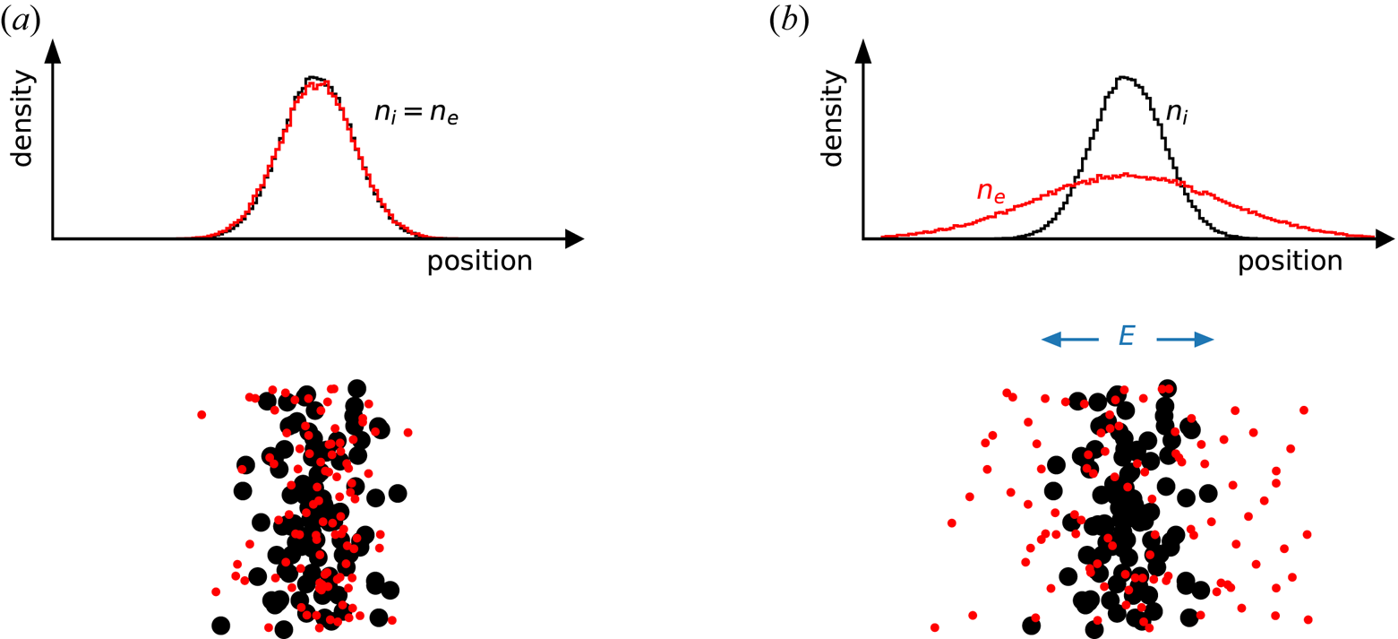
Now consider the same pressure perturbation in a quasineutral electron–positron plasma with equal temperatures ( $T_e = T_p$). Here, no electric field develops; the two species escape a high-pressure region at the same rate since they have the same mass and the same thermal speed. With no electric field and only very rare collisions, no coherent wave appears. Instead the plasma simply relaxes and eliminates the pressure perturbation through free streaming of the particles. Even if collisions were present, this perturbation would result in an ordinary sound wave, as in a neutral gas, rather than a collective plasma wave, although some coupling of density and potential perturbations is restored if the temperatures or densities of the two species are not the same.
1.2. Ramifications for plasma turbulence: the universal instability may not be universal
Remarkably, the above-mentioned result can be generalized to include a much wider class of wave phenomena, turbulence and instabilities, which are common in conventional plasmas. Many (electron–ion) plasmas in the laboratory are magnetized; they interact with an external magnetic field, and the radius of the cyclotron motion that particles undergo around the field lines (the Larmor radius,  $\rho _L=mv_{\perp }/qB$, where $m$ is the mass, $v_{\perp }$ is the velocity perpendicular to the magnetic field $B$, and $q$ is the charge) is much smaller than the typical length scale of the plasma. This is also true for many astrophysical plasmas. A magnetized plasma is anisotropic, because the plasma can flow rather freely along the magnetic field, but only drifts slowly across the magnetic field. This is the fundamental reason why a plasma can be confined efficiently by toroidal magnetic topologies. The anisotropy introduced by the magnetic field also leads to complex and often nonlinear behaviour.
In a magnetically confined plasma with a gradient in the thermal pressure, the ion acoustic wave physics described above is modified. While the dynamics parallel to the confining magnetic field are essentially the same as the ion acoustic wave, the component of the wave electric field perpendicular to the confining magnetic field produces an ExB drift. In the presence of the pressure gradient, this results in the basic drift wave that propagates in the direction of and at a phase velocity in the range of the electron diamagnetic drift. In the presence of collisions or other kinetic effects (associated with particles flowing near and therefore in resonance with the wave phase speed), there is a phase shift between the electric potential perturbation of the wave and the density perturbation. This phase shift equates to net transport of particles and energy down the gradient and the liberated thermal energy causes the wave to grow in amplitude. Since every real, bounded, magnetized plasma, whether in the lab or in nature possesses pressure gradients, this drift wave instability is ubiquitous and is therefore known as the universal instability. Note, however, that for the same reasons that the ion acoustic wave is suppressed in a pair plasma because the equal masses of the positive and negative charged particles eliminates the electric field that sustains it; drift waves and their associated instabilities should also be largely absent in such systems possessing a confining magnetic field.
A number of versions of the universal instability are fundamental to fusion and many astrophysical plasmas, and frequently evolve into broadband microturbulence – that is, fluctuations of plasma parameters (density, temperature, etc.) on spatial scales comparable to or smaller than the ion Larmor radius  $\rho _{L,i}$. Turbulence changes the macroscopic behaviour of the plasma significantly, since it allows transport of particles, momentum and energy across the magnetic field at rates that are orders of magnitude higher than those predicted from single-particle orbits and the binary interactions of particles (i.e. classical and neoclassical transport). This ‘anomalous transport’ has been known in fusion energy for more than half a century and it is being recognized more and more that such collective electrostatic or electromagnetic processes also play a major role in many astrophysical settings. In magnetized electron–positron plasmas, although they share the anisotropic features of magnetized electron–ion plasmas, turbulence is predicted to be greatly suppressed, and, therefore, anomalous transport processes are expected to be reduced (Tsytovich & Wharton Reference Tsytovich and Wharton1978; Helander Reference Helander2014; Helander & Connor Reference Helander and Connor2016).
Recently, an analytical treatment in a parameter regime relevant to planned laboratory incarnations of low-density, magnetically confined pair plasmas showed that complete stability can be expected (Helander Reference Helander2014). In addition to the mass symmetry of pair plasmas, this gyrokinetic approach assumed a collisionless, low-density regime where the Debye length (the length scale over which potential perturbations are collectively screened out), while much smaller than the system size, is larger than the Larmor radius. It is in this parameter regime where the stability is most robust. The main result is best summed up with a quote from Helander's paper (Helander Reference Helander2014): ‘in summary, it has been found that the electrostatic instabilities causing turbulence and transport in magnetically confined electron–ion plasmas are largely absent in low-density electron–positron plasmas’. This work has been subsequently extended by analytic as well as computational methods, to include electromagnetic effects (Helander & Connor Reference Helander and Connor2016), geometric effects associated with a magnetic dipole geometry (Mishchenko, Plunk & Helander Reference Mishchenko, Plunk and Helander2018a; Kennedy et al. Reference Kennedy, Mishchenko, Xanthopoulos, Helander, Navarro and Görler2020), tokamak and stellarator configurations (Kennedy et al. Reference Kennedy, Mishchenko, Xanthopoulos and Helander2018; Horn-Stanja et al. Reference Horn-Stanja, Biancalani, Bottino and Mischenko2019), contamination of a positron–electron plasma by ions (Mishchenko et al. Reference Mishchenko, Zocco, Helander and Könies2018b) and non-neutrality of the positron–electron plasma (Kennedy & Mishchenko Reference Kennedy and Mishchenko2019). In certain magnetic geometries (including the dipole and the stellarator) and in certain parameter regimes, one can even show that nonlinear stability prevails (Helander Reference Helander2017). These theoretical and computational studies reveal a parameter-regime landscape that includes stable and unstable terrain that is ripe for experimental exploration. For example, stability relies on the symmetry not only of the masses, but also of the spatial and velocity-space distributions. If the temperature of the positrons and electrons (or their gradient scale lengths) differ, instability can arise. This could be tested experimentally by preferentially heating one species with circularly polarized electromagnetic waves at the cyclotron resonant frequency. Such tests are likely to be the ‘cleanest’ tests of gyrokinetic theory predictions to date for two reasons. Firstly, the plasma beta (the ratio of the plasma thermal pressure to the magnetic pressure) will be very small ( $\beta < 10^{-6}$) making the simplest electrostatic version of gyrokinetic theory wholly applicable. Secondly, the order parameter on which gyrokinetic theory is based, the ratio of the Larmor radius to the system size, will also be at least an order of magnitude smaller than for typical fusion plasmas ( $\epsilon = \rho _L / L < 10^{-4}$).
While the drive for microturbulent instabilities is expected to be much reduced in low-density magnetically confined pair plasmas, at the same time such systems are expected to have enhanced classical transport. The reason for this is that the Debye length will be much larger than the Larmor radius. Binary interactions between charged particle pairs with impact parameters larger than the Larmor radius can, therefore, dominate the collision dynamics. This regime is not so common in typical electron–ion plasma, but it is characteristic of non-neutral plasmas (Dubin Reference Dubin1998). These long-range collisions, in which particle pairs ExB drift in the electric fields of one another as they stream past each other, introduces a random walk step size of the order of the Debye length rather than the Larmor radius. Since the Debye length scales as the inverse square root of the density, whereas the Larmor radius (which is the step size for collisional transport in the usual regime) is independent of density, the classical Coulomb transport associated with low density pair plasmas could be the dominant transport mechanism. If this is verified experimentally, it would be the first time that a magnetically confined quasi-neutral plasma is free of anomalous transport.
For the reasons described here, low-density, magnetized pair plasma experiments constitute a stringent test of our ability to predict plasma phenomena on length and time scales not covered by magnetohydrodynamics. Such phenomena are generally qualitatively different in pair plasmas and conventional plasmas whereas the magnetohydrodynamics equations are the same, being oblivious to the nature of the charge carriers as long as these are frozen into the magnetic field. A wealth of research on plasma instability, turbulence and associated transport exists for magnetized plasmas, and tremendous progress has been made in the last few decades, but even with sophisticated present-day codes and theories, experiments and astrophysical observations still offer surprises. We do not yet have the power to quantitatively predict plasma behaviour in many situations where it would be highly desirable to do so due to the extremely sensitive conditions for onset of certain instability mechanisms and their nonlinear interactions. Nor can we reliably predict the nonlinear saturation of these instabilities.
1.3. Instabilities in relativistic pair plasma
Theoretical work aimed at explaining intense non-thermal radiation from astrophysical phenomena such as gamma-ray bursts (GRB) has focused on particle acceleration in collisionless shocks formed through Weibel-like instabilities (Weibel Reference Weibel1959) in relativistic electron–positron plasma (Yang et al. Reference Yang, Gallant, Arons and Langdon1993). Weibel instabilities are transverse modes in plasmas with momentum anisotropy, a simple example being two counter-streaming beams. Gruzinov (Reference Gruzinov2001) and Chen (Reference Chen1984) provide intuitive explanations of this instability as follows. While oppositely directed flow of plasma may have no net current, oppositely charged particles in the flow can be thought of as oppositely directed currents. Small perturbations due to a seed magnetic perturbation can create net current filaments parallel to the flow. These current filaments are amplified (i.e. are unstable) due to the magnetic attraction of like currents. The resulting transverse magnetic fields inhibit the flow leading to a collisionless shock. However, counter-streaming plasmas have many unstable modes including longitudinal electrostatic streaming instabilities which are usually the fastest growing modes in non-relativistic regimes (Bret et al. Reference Bret, Stockem, Fiuza, Ruyer, Gremillet, Narayan and Silva2013). Which instability dominates in relativistic plasmas is determined by the ratio of thermal to directed momentum in the plasma and the mass ratio of the charge particles (Stockem et al. Reference Stockem, Fiuza, Bret, Fonseca and Silva2014). Mass symmetry of a pair plasma enables Weibel instability mediated shocks to form 100 times faster than in proton–electron plasmas (Bret et al. Reference Bret, Novo, Narayan, Ruyer, Dieckmann and Silva2016), making laboratory pair plasmas an attractive test bed for these instabilities. Indeed, there are several efforts underway to create collisionless shocks with (unmagnetized) pair beams (Liang et al. Reference Liang, Clarke, Henderson, Fu, Lo, Taylor, Chaguine, Zhou, Hua and Cen2015; Warwick et al. Reference Warwick, Dzelzainis, Dieckmann, Schumaker, Doria, Romagnani, Poder, Cole, Alejo and Yeung2017). In the weakly magnetized experiments, where the gyroradius is of the order of the plasma size positrons and electrons naturally form, counter-streaming flows due to their opposite directed gyration. Strong magnetization modifies the hierarchy of electrostatic and electromagnetic instability growth rates in counter-streaming pair plasmas (Bret Reference Bret2016). Magnetized relativistic pair plasma experiments could provide complementary viewpoints in this physics.
1.4. Timeliness of electron–positron plasma studies
Given the considerations presented in §§ 1.2 and 1.3, experiments with pair plasmas will provide important benchmarks for predicting the behaviour of both conventional and pair plasmas, whether found astrophysically or in the laboratory. Electron–positron plasma studies are particularly timely because of recent innovations in antimatter physics. Experimental methods in this area are rapidly progressing, fuelled by dramatic advances in particle beam and laser–matter interaction techniques. For example, the last 10 years have seen a tremendous increase in the production of relativistic positrons at pulsed power laser labs (Chen et al. Reference Chen, Fiuza, Link, Hazi, Hill, Hoarty, James, Kerr, Meyerhofer and Myatt2015b; Sarri et al. Reference Sarri, Poder, Cole, Schumaker, Di Piazza, Reville, Dzelzainis, Doria, Gizzi and Grittani2015), while the ability to moderate and accumulate antimatter from energetic beams has opened opportunities for novel research in interdisciplinary fields. At the antiproton decelerator (AD) facility of CERN (Maury Reference Maury1997), the formation of a large number of antihydrogen atoms was achieved in 2002 (Amoretti et al. Reference Amoretti, Amsler, Bonomi, Bouchta, Bowe, Carraro, Cesar, Charlton, Collier and Doser2002; Gabrielse et al. Reference Gabrielse, Bowden, Oxley, Speck, Storry, Tan, Wessels, Grzonka, Oelert and Schepers2002). Further studies aim to make stringent tests of charge, parity, and time reversal (CPT) symmetry and are already reporting significant measurements of the 1S–2S transition in antihydrogen (Ahmadi et al. Reference Ahmadi, Alves, Baker, Bertsche, Butler, Capra, Carruth, Cesar, Charlton and Cohen2017a) and of its hyperfine splitting (Ahmadi et al. Reference Ahmadi, Alves, Baker, Bertsche, Butler, Capra, Carruth, Cesar, Charlton and Cohen2017b). The intense antiproton beam from the AD has also made it possible to study ‘exotic’ atoms that consist of matter and antimatter (Yamazaki et al. Reference Yamazaki, Widmann, Hayano, Iwasaki, Nakamura, Shigaki, Hartmann, Daniel, von Egidy and Hofmann1993). In the history of research in antimatter sciences, many fundamental ideas and key techniques were adopted from plasma physics (Danielson et al. Reference Danielson, Dubin, Greaves and Surko2015; Davidson Reference Davidson2001). These include electromagnetic trapping configurations for charged (and even neutral) particles, diagnostic techniques using collective modes, and manipulation techniques for confined charged particles (Danielson et al. Reference Danielson, Dubin, Greaves and Surko2015). Although plasma physics has contributed in important practical ways to antimatter physics, there is still a large unexplored field of matter–antimatter plasma physics, where collective phenomena of many body systems play an essential role. It is here that experimental studies of electron–positron plasmas can make an important new contribution.
The goal of the projects described in subsequent sections of this paper is to produce quasi-neutral combinations of electrons and positrons at densities sufficient to exhibit collective plasma behaviour, and persisting for times long enough to begin exploring some of the physics effects described above. Our focus therefore is on generating and confining pair plasmas. Using magnetic fields not only allows us to explore the physics of magnetized systems, it also allows us to accumulate larger numbers of particles and isolate them for longer times. This effort is being pursued along at least two predominant paths: magnetic confinement of (i) low-density pair plasmas; and (ii) relativistic pair plasmas generated by intense laser–matter interactions.
2. Magnetic confinement of low-density pair plasmas
2.1. Levitated dipole and stellarator
A device for the confinement of a low-density pair plasma must be able to confine particles with both signs of charge. Although excellent confinement of either positrons or electrons can be achieved in a Penning–Malmberg trap, this configuration cannot simultaneously confine both positively and negatively charged particles with a spatial overlap greater than the Debye length (Yoshida et al. Reference Yoshida, Ogawa, Morikawa, Himura, Kondo, Nakashima, Kakuno, Iqbal, Volponi and Shibayama1999; Andresen et al. Reference Andresen, Bertsche, Boston, Bowe, Cesar, Chapman, Charlton, Chartier, Deutsch and Fajans2007; Saitoh et al. Reference Saitoh, Mohri, Enomoto, Kanai and Yamazaki2008; Pedersen et al. Reference Pedersen, Danielson, Hugenschmidt, Marx, Sarasola, Schauer, Schweikhard, Surko and Winkler2012; Kuroda et al. Reference Kuroda, Ulmer, Murtagh, Van Gorp, Nagata, Diermaier, Federmann, Leali, Malbrunot and Mascagna2014). Nevertheless, Greaves & Surko (Reference Greaves and Surko1995), as well as Gilbert et al. (Reference Gilbert, Dubin, Greaves and Surko2001), observed collective effects involving sufficiently dense populations of both species. They passed an electron beam through a positron plasma confined in a Penning–Malmberg trap and excited a two-stream instability. Pair plasma confinement in a magnetic mirror device is also being explored (Boehmer, Adams & Rynn Reference Boehmer, Adams and Rynn1995; Higaki et al. Reference Higaki, Sakurai, Ito and Okamoto2012), although this approach suffers from a loss-cone instability. Higaki et al. are pursuing this approach and have simultaneously trapped 10 $^7$ electrons and 10 $^5$ positrons for times as long as 70 ms, although the density was too low for collective effects to emerge (Higaki et al. Reference Higaki, Kaga, Fukushima, Okamoto, Nagata, Kanai and Yamazaki2017). As discussed in § 3, mirror confinement is also being developed to trap laser produced electron–positron plasmas. Paul traps are used to trap charged plasmas and have the potential to trap electron–positron plasma (Hicks, Bowman & Godden Reference Hicks, Bowman and Godden2019), although heating of the particles due to coupling with the radiofrequency (RF) fields that form the trapping potential must be overcome. The combination of a Penning trap and a Paul trap was first suggested by Greaves to study pair plasmas (Greaves & Surko Reference Greaves and Surko2002), but this also has issues controlling the subsequent heating from the trapping RF fields.
In contrast to conventional linear configurations, where axial confinement is realized by plugging electrostatic fields, toroidal configurations have no open ends. Some toroidal geometries can also confine charged particles of both signs together, as a plasma, at any degree of non-neutrality. The two configurations that have this property and are being pursued are the magnetic dipole and the stellarator. The dipole concept has been the focus of recent work. The idea of dipole confinement itself dates back to early fusion studies in the 1960s and 1970s (Freeman et al. Reference Freeman, Johnson, Okabayashi, Pacher, Schmidt and Yoshikawa1971). Besides its application to fusion science, the dipole field is one of the most fundamental magnetic configurations found in the universe. Motivated by satellite observations of high-pressure flowing plasmas in the Jovian magnetosphere (Krimigis et al. Reference Krimigis, Armstrong, Axford, Bostrom, Fan, Gloecker, Lanzerotti, Keath, Zwickl and Carbary1979), the dipole confinement concept has attracted a renewed interest in recent years. In a laboratory, use of a levitated coil to produce the dipole field is essential, as otherwise mechanical support structures would impair the magnetic confinement and cause unacceptable particle losses. Two experiments, the Ring Trap 1 (RT-1) at The University of Tokyo (Yoshida et al. Reference Yoshida, Saitoh, Morikawa, Yano, Watanabe and Ogawa2010) and the Levitated Dipole Experiment (LDX) at MIT (Boxer et al. Reference Boxer, Bergmann, Ellsworth, Garnier, Kesner, Mauel and Woskov2010), have achieved high-performance plasma confinement in levitated dipole configurations.
The dipole magnetic field is characterized by a strong field gradient. As observed in planetary magnetospheres and experiments in RT-1 and LDX, charged particles in an inhomogeneous dipole field exhibit interesting self-organization and complex nonlinear dynamics (Yoshida et al. Reference Yoshida, Saitoh, Yano, Mikami, Kasaoka, Sakamoto, Morikawa, Furukawa and Mahajan2013). The high compressibility of the dipole field provides remarkable stability for plasmas even in the presence of a strong pressure gradient. Contrary to the naive expectation, diffusion in such plasmas leads to a plasma density profile strongly peaked towards the dipole magnet (Yoshida et al. Reference Yoshida, Saitoh, Yano, Mikami, Kasaoka, Sakamoto, Morikawa, Furukawa and Mahajan2013). These unique self-organization and inward-transport processes play important roles in penetration of solar wind particles and structure formation in magnetospheres (Schulz & Lanzerotti Reference Schulz and Lanzerotti1974). Moreover, we can use such properties of the dipole field for scientific applications. The strong inward particle pinch and the very high plasma pressure attainable in a dipole makes it feasible to consider advanced fusion fuels for future power production (Hasegawa, Chen & Mauel Reference Hasegawa, Chen and Mauel1990), as intensively studied in RT-1 and LDX.
Dipole confinement of non-neutral plasmas has also been studied at RT-1 (Ogawa et al. Reference Ogawa, Yoshida, Morikawa, Saito, Watanabe, Yano, Mizumaki and Tosaka2009). In pure electron plasma experiments, detailed measurements of the internal potential structure and electrostatic fluctuations revealed a remarkable self-organization process for dipole non-neutral plasmas (Saitoh et al. Reference Saitoh, Yoshida, Morikawa, Yano, Watanabe and Ogawa2010). After turbulence-induced inward-diffusion transported the injected electrons into a strong field region, a rigidly rotating equilibrium state was spontaneously generated in the dipole field. This relaxed state was so robust that, of order  $10^{10}$ electrons were stably trapped for more than 300 s, which is a world record for confinement of a non-neutral plasma in a toroidal geometry.
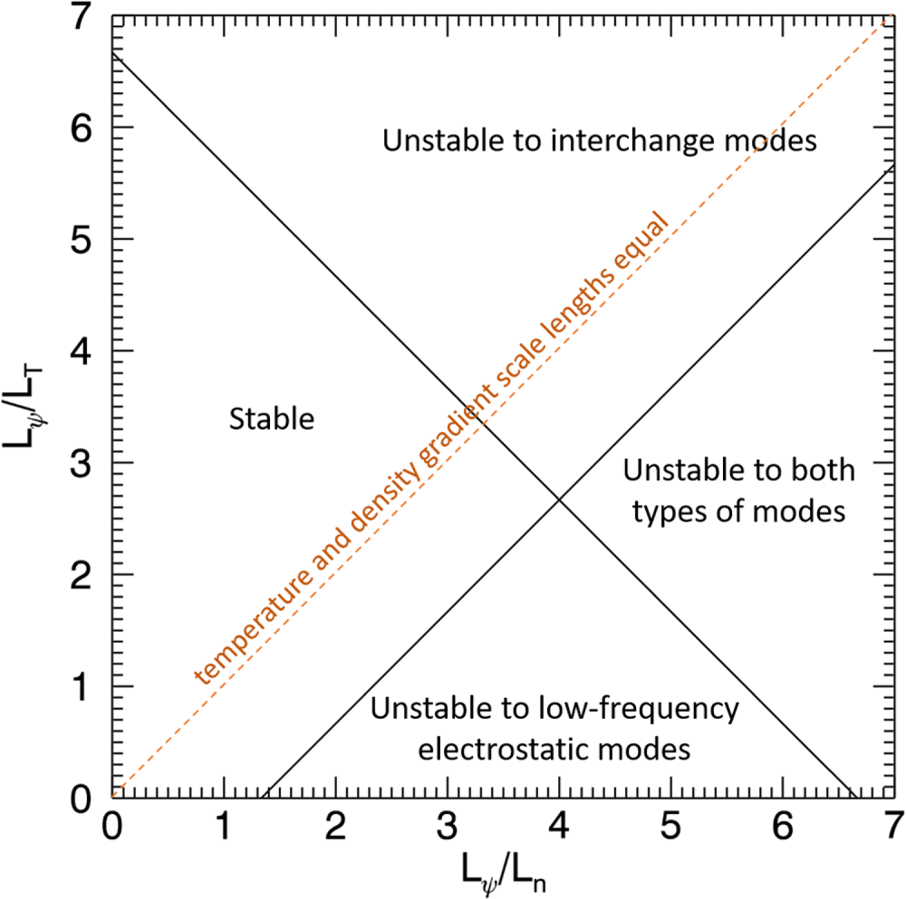
Helander & Connor have examined the stability of low-density, quasineutral pair plasmas in a magnetic dipole to both low-frequency, magnetic curvature driven electrostatic instabilities and interchange modes (Helander & Connor Reference Helander and Connor2016). The stability diagram shown in figure 2 is adapted from their paper. In this figure the abscissa and ordinate axes are, respectively, the inverse density gradient scale length (normalized to the scale length for variation of the magnetic flux) and the inverse of the normalized temperature gradient scale length. The unstable regions for interchange and low-frequency electrostatic modes are labelled. Despite the exceedingly low plasma  $\beta$ (likely to be in the range of $< 10^{-6}$), Helander & Connor predict the possibility of interchange instability, which is possible because the field lines close on themselves and do not need to be bent. The interchange mode in question is, in fact, electrostatic in nature. There is, however, a large region in this parameter space that is linearly stable to both of these types of modes. This is the region of flatter profiles, especially for the density. These theoretical predictions have recently been confirmed by direct gyrokinetic simulations (Kennedy et al. Reference Kennedy, Mishchenko, Xanthopoulos, Helander, Navarro and Görler2020). Moreover, one can show that a subset of the linearly stable region is even nonlinearly stable (Helander Reference Helander2017). To set the scale of the axes, the scale length for the variation of the magnetic flux in a point dipole varies as the first power of $r$, the radial coordinate. Experiments in LDX and RT-1 observed self-generated peaking of the density profile in the strong field region near the levitating coil. However, in the absence of the onset of turbulence, it is not clear that such a mechanism would be operative in a low-density pair plasma. Even if the profiles are up to three times steeper than the fall-off in the magnetic flux, theory predicts the system should be stable (depending on the relative temperature and density gradients). If the confinement is very good, cyclotron cooling may be effective at flattening (or even inverting) the temperature gradient as this process is more efficient in the strong field region which could destabilize electrostatic modes.
The stability landscape for pair plasma in a magnetic dipole (adapted from figure 1 in Helander & Connor Reference Helander and Connor2016) showing the stability boundaries for interchange and low-frequency electrostatic modes in the space of normalized inverse temperature gradient scale length versus normalized inverse density gradient scale length. The dashed line with unit slope indicates the contour where the temperature and density gradients are equal.
The stellarator is another suitable configuration for trapping toroidal plasmas, both quasi-neutral and non-neutral (Wakatani Reference Wakatani1998), that is being pursued as a concept for electron–positron plasma studies. The stellarator is one of the promising magnetic configurations for nuclear fusion power production, and is one in which closed magnetic surfaces are generated solely by external coils. The Columbia Non-neutral Torus (CNT) (Pedersen & Boozer Reference Pedersen and Boozer2002) was designed and operated for the purpose of studying pure electron plasmas in a stellarator, with the ultimate goal of paving the way for the creation of an electron–positron plasma. In CNT, stable equilibrium (Kremer et al. Reference Kremer, Pedersen, Lefrancois and Marksteiner2006) and relatively long confinement of an electron plasma for more than 90 ms were demonstrated (Brenner & Pedersen Reference Brenner and Pedersen2012), which is much longer than the time scales of most plasma phenomena. The stellarator has the advantage that the confinement configuration can be generated by mechanically supported coils. This is in marked contrast to the levitated dipole experiment. The stellarator is, in several respects, a complementary magnetic confinement device to a levitated dipole for the purposes of understanding the basic plasma physics behaviour. Some of the complementary features of the two configurations are listed in table 1.
Comparison of stellarator and levitated dipole for confining electron–positron plasma.

2.2. Target parameters for magnetically confined pair plasma experiments
The APEX (a positron–electron experiment) and EPOS (electrons and positrons in an optimized stellarator) (Stenson Reference Stenson2019) projects aim to create electron–positron plasmas in levitated dipole and stellarator configurations, respectively. As explained below, in order to observe self-generated collective behaviour of the charged particles, the Debye length ( $\lambda _D=\sqrt {\epsilon _0 k_BT/(2n_e e^2)}$, where $\epsilon _0$ is the vacuum permittivity, $k_B$ is Boltzmann's constant, $n_e=n_p$ is the density, and the factor of 2 reflects the equal contribution to screening effects due to each species) must be smaller than the spatial scale length of the plasma. These experiments target the creation of plasmas with number densities in the range of $10^{11}\text {--}10^{13}\ \textrm {m}^{-3}$ and typical temperatures of $k_BT =0.1\text {--}1\ \textrm {eV}$. This corresponds to Debye lengths in the range of $\lambda _D$ of 0.1–1 cm, which is significantly smaller than the plasma size of approximately 8 cm. These parameters are shown in the orange region of figure 3(a) in comparison with the planned parameter regime for mirror confined relativistic plasma (discussed below) and with results of pure electron plasma experiments in RT-1 (a levitated dipole) (Saitoh et al. Reference Saitoh, Yoshida, Morikawa, Yano, Watanabe and Ogawa2010) and CNT (a stellarator) (Brenner & Pedersen Reference Brenner and Pedersen2012). The target density range is comparable to the electron densities realized in the previous non-neutral plasma experiments, indicating that this aim is realistic in view of the confinement performance of the trapping configuration. The confinement volume of APEX or EPOS will be approximately $10^{-2}\ \textrm {m}^3$ (10 l), which is smaller than those of the previous two experiments (1000 l for RT-1 and 100 l for CNT). Thus, the small Debye length criterion can be satisfied with a smaller number of charged particles (Pedersen et al. Reference Pedersen, Danielson, Hugenschmidt, Marx, Sarasola, Schauer, Schweikhard, Surko and Winkler2012); effective injection of order $10^{10}\text {--}10^{11}$ positrons in APEX or EPOS will be needed (along with the same number of electrons). Figure 3(b) shows anticipated ranges for the plasma size divided by the Debye length (ordinate) versus the plasma size divided by the skin depth (discussed further in § 3). $(a)$ Target parameters (temperature and density) for pair plasma experiments discussed in this paper: low-density magnetically confined plasmas (orange) and relativistic laser-produced plasmas (blue). Also shown are achieved parameters for non-neutral plasmas in a levitated dipole (RT-1) and a stellarator (CNT). The contours indicate the Debye length (long dash) and skin depth (short dash) at each combination of density and temperature. $(b)$ Planned operating regimes of the relativistic pair mirror (blue) and low-density (low-temperature) magnetically confined pair plasma (orange) in terms of the plasma size, $L$, as a ratio of the Debye length, $\lambda _D$, versus as a ratio of the skin depth, $\lambda _s$.

At typical pressures in ultra-high vacuum systems ( $10^{-8}\ \textrm {Pa}$) the density of neutrals will be comparable to those of the charged species, nevertheless, unless the plasma temperature exceeds approximately 1 eV, ion contamination is not expected to be a significant effect. Diffusion due to elastic scattering of charged particles with neutrals and positron annihilation are effects to consider. Given cross-sections for expected residual (or introduced) gases, we estimate diffusion time scales for the planned experiments to be more than 1000 s. Annihilation effects are treated in the subsequent section.
2.3. Annihilation of positrons does not rule out long confinement
Before considering accumulation and injection methods for positrons it is worth noting that annihilation effects neither impede the production nor the study of long-lived electron–positron plasmas for realistically achievable parameters (Greaves & Surko Reference Greaves and Surko2002; Saitoh et al. Reference Saitoh, Pedersen, Hergenhahn, Stenson, Paschkowski and Hugenschmidt2014). These considerations are summarized in figure 4 for magnetically confined low-density pair plasmas. One might expect that direct annihilation would be a serious obstacle to the experimental efforts described in this paper. However, the cross-section for direct annihilation of positrons with electrons is determined by the classical electron radius, which is very small. Due to Coulomb focusing at low energies, direct annihilation is enhanced for lower plasma temperatures (Crannell et al. Reference Crannell, Joyce, Ramaty and Werntz1976; Gould Reference Gould1989), however, the limitations on plasma lifetime based on this process, which scales inversely with the plasma density, is many days for the target densities and temperatures (purple lines). Positronium (Ps) formation via radiative recombination is a faster process than direct annihilation for temperatures below 59 eV (Gould Reference Gould1989); the lifetime associated with this process also scales inversely with density and is many hours for the anticipated experimental densities (green lines). As far as the authors are aware, there is no complete theory for the rate of three-body recombination in a positron–electron plasma. For electron–proton (or positron–antiproton) plasmas, the rate of three-body recombination has been calculated and found to scale as  $n^2/T^{9/2}$ (Glinsky & O'Neil Reference Glinsky and O'Neil1991). We anticipate a similar rate for Ps formation, which is expected to be negligible compared with radiative recombination unless the plasma temperature becomes very low ( ${<}0.01\ \textrm {eV}$); the blue lines in figure 4 use the results of Glinsky & O'Neil (Reference Glinsky and O'Neil1991) but assume no magnetic field (approximately 11 times faster than the strong field rate) and an additional factor of two enhancement to account for the presence of twice the number third particles (both positrons and electrons) compared with the comparable process in an electron–ion plasma.
Lifetimes associated with annihilation of positrons versus plasma density (at temperatures of 0.1 eV and 1 eV) set by direct annihilation with plasma electrons (purple), Ps formation via radiative recombination (green) and via three-body recombination (blue); lifetimes for positrons set by direct annihilation on atomic/molecular electrons (in red, for two gas composition and pressure values), and by Ps formation via charge exchange on atomic hydrogen at various plasma temperatures (yellow). The anticipated experimental range for low-density magnetically confined plasma experiments is indicated in grey. This figure is adapted from similar figures in Greaves & Surko (Reference Greaves and Surko2002) and Saitoh et al. (Reference Saitoh, Pedersen, Hergenhahn, Stenson, Paschkowski and Hugenschmidt2014).

Additional relevant effects involve interactions with neutral gas. In addition to residual gases associated with imperfect vacuum conditions (e.g.  $N_2$), gas may be intentionally introduced as part of the process for cooling the superconducting coils (He), for the purposes of cooling the plasma (Natisin, Danielson & Surko Reference Natisin, Danielson and Surko2014), and to serve as annihilation target for diagnostic purposes (probably using noble gases (Kurz, Greaves & Surko Reference Kurz, Greaves and Surko1996)). Direct annihilation with the bound electrons in neutral atoms and molecules (Iwata, Greaves & Surko Reference Iwata, Greaves and Surko1997) depends on the neutral pressure and composition, but is independent of plasma density; this process has a weak temperature dependence and the red lines in figure 4 use the low-temperature limit (Kurz et al. Reference Kurz, Greaves and Surko1996). For base pressures in the range of $10^{-6}\ \textrm {Pa}$, this process could limit positron lifetimes to of order an hour and motivates the desire to achieve ultra-high vacuum conditions. Positronium formation via charge-exchange collisions have relatively large, but energy dependent cross-sections (Zhou et al. Reference Zhou, Li, Kauppuila, Kwan and Stein1997) and could limit the positron lifetime; in particular, charge-exchange reactions have a threshold energy that is the difference in the binding energies of the electron with the atom/molecule and that of Ps (6.8 eV). For atomic hydrogen, which is a residual gas in ultra-high vacuum systems and has a relatively small binding energy, the threshold energy is 6.8 eV, and even at plasma temperatures of 1 eV and partial pressures of $10^{-8}\ \textrm {Pa}$ could lead to substantial positron losses (yellow lines). The lifetime limit based on charge-exchange reactions in figure 4 is not likely to be as pessimistic as this calculation indicates since energetic positrons in the tail of the velocity distribution would be preferentially lost, leading to rapid cooling and a reduction in the strongly temperature-dependent loss rate. In fact, $H_2$ might be used to cool the plasma via inelastic collisions that excite vibrational and rotational states. Molecular hydrogen has a similar maximum cross-section to atomic hydrogen, but a somewhat higher threshold energy (8.6 eV). The main conclusion here is that annihilation processes do not forbid the study of positron–electron plasma in the parameter range of interest for time scales of the order of minutes, which is much longer than the time scales of most plasma phenomena and would be a record long-confinement time for a quasi-neutral plasma.
2.4. The importance of a small Debye length
Collective plasma behaviour is expected when the Debye length is smaller than the size of the plasma (Chen Reference Chen1984; Bittencourt Reference Bittencourt2004; Hazeltine & Waelbroeck Reference Hazeltine and Waelbroeck2004; Piel Reference Piel2010). For example, self-generated electrostatically driven dynamics lead to the drift-wave type turbulence described in § 1. The same drivers are strong candidates for causing a whole host of other complex phenomena, such as the anomalously fast rate of magnetic reconnection, the larger than expected rate of inward transport in accretion disks, and the larger than expected rates of outward transport in fusion experiments. Such phenomena occur if the electrostatic potential is large enough that it substantially affects the motion of many plasma particles. This is generally true if  $e\phi /k_BT$ is not negligibly small, with $\phi$ the electric potential and $e$ the electron charge. A requirement is therefore that the absolutely largest conceivable potential perturbation that can be created by a plasma satisfies $e\phi _{\max }/k_BT \approx 1$.
The maximal space charge that a plasma with density  $n$ can create, results if one species entirely leaves the other species behind. In this case, the space charge electrostatic potential can be estimated from Poisson's equation. We assume for simplicity a spherical plasma with radius $L$ and constant density of the remaining species, which is singly charged:
 \begin{equation} {\epsilon_0}{\nabla^2}{\phi} = en \Longleftrightarrow {\epsilon_0}{\frac{1}{r^2}\frac{\partial}{\partial{r}}\left(r^2\frac{\partial\phi}{\partial{r}}\right) = en \Longrightarrow |\phi_{\max}|=\frac{1}{6\epsilon_0}enL^2}. \end{equation}
Combining this with our requirement that the maximum normalized potential perturbation be close to unity, we get
 \begin{equation} \frac{e}{k_BT}\frac{enL^2}{6\epsilon_0} \approx 1 \Longleftrightarrow L^2 \approx 6\frac{\epsilon_0k_BT}{ne^2} \Longleftrightarrow L^2 \approx 6{\lambda_D}^2 \Longleftrightarrow \lambda_D \approx \frac{L}{\sqrt{6}}. \end{equation}
That is, the Debye length should be smaller than the plasma size, otherwise the charge cloud is too thin or too hot for electrostatic dynamics to play a role. If one resorts to a more realistic model, in which one species of particles is not entirely separated from the other, then a stricter upper bound on the Debye length results. Most textbooks require  $\lambda _D \ll L$ without specifying what that exactly means; we take it to mean
 \begin{equation} \lambda_D < \frac{L}{10}. \end{equation}
The creation of electron–positron plasmas with Debye lengths satisfying this criteria have not yet been achieved on Earth for a cloud of simultaneously confined electrons and positrons, although numerous theoretical and numerical studies of pair plasmas show that they behave very differently from traditional plasmas regarding such self-generated collective dynamics (e.g. microinstabilities) (Zank & Greaves Reference Zank and Greaves1995; Pedersen et al. Reference Pedersen, Boozer, Dorland, Kremer and Schmitt2003; Helander Reference Helander2014). A more comprehensive discussion of Debye-length physics of pair plasmas can be found in the paper by Stenson et al. (Reference Stenson, Horn-Stanja, Stoneking and Pedersen2017).
2.5. Plans for the APEX levitated dipole and the EPOS optimized stellarator
The biggest obstacle to creating electron–positron plasmas is the difficulty of obtaining sufficient quantities of positrons. This reality argues for construction of a small experiment. At fixed density, the number of positrons required would scale as the cube of the system size,  $L$. However, as discussed above, to realize collective plasma effects, there must be many Debye lengths in the system. To maintain a fixed number of Debye lengths as $L$ is varied (at fixed temperature), the density must vary as the inverse square of the size and the total number of required positrons therefore varies linearly with spatial scale (Pedersen et al. Reference Pedersen, Danielson, Hugenschmidt, Marx, Sarasola, Schauer, Schweikhard, Surko and Winkler2012). So, a smaller experiment requires fewer positrons, but the effective scaling is much weaker than the cube of $L$. The competing considerations of wanting to produce closed magnetic field traps with strong fields and system sizes that can be spatially resolved with annihilation gamma detectors placed remotely, lead to the choice of a tabletop experiment with confinement volumes of approximately 10 l.
To achieve the target parameters discussed above (and displayed in figure 3), the minimum number of required positrons is approximately  $10^{10}$. Typical radioactive sources used to produce non-neutral positron plasmas can generate up to $10^7$ positrons per second (Danielson et al. Reference Danielson, Dubin, Greaves and Surko2015). Higher positron fluxes can be obtained from nuclear reactor based sources (up to $10^9$ per second), although at these fluxes, the positrons typically require further remoderation to produce brightness enhanced beams with the properties suitable for efficient injection and trapping. Nevertheless, the higher flux available from the neutron-induced positron source at Munich (NEPOMUC) makes it the source of choice for the APEX and EPOS projects (Hugenschmidt et al. Reference Hugenschmidt, Piochacz, Reiner and Schreckenbach2012). The NEPOMUC beam has been characterized at the beam port where positrons are delivered to the APEX experiment and tailored for the injection and confinement experiments described below (Stanja et al. Reference Stanja, Hergenhahn, Niemann, Paschkowski, Pedersen, Saitoh, Stenson, Stoneking, Hugenschmidt and Piochacz2016).
The APEX/EPOS plan for producing magnetically confined pair plasmas is shown schematically in figure 5 (Stoneking et al. Reference Stoneking, Saitoh, Singer, Stenson, Horn-Stanja, Pederson, Nil, Hergenhahn, Yanagi and Hugenschmidt2018). The positron beam from the NEPOMUC source is sent to the buffer gas trap system (BGTS) (Danielson et al. Reference Danielson, Dubin, Greaves and Surko2015). Such devices are the standard apparatus in positron research and have also been adapted for use in the creation of antihydrogen (Gabrielse et al. Reference Gabrielse, Bowden, Oxley, Speck, Storry, Tan, Wessels, Grzonka, Oelert and Schepers2002; Andresen et al. Reference Andresen, Bertsche, Boston, Bowe, Cesar, Chapman, Charlton, Chartier, Deutsch and Fajans2007). In these traps, positrons suffer inelastic collisions with an N $_2$ buffer gas and a cooling gas (typically SF $_6$ or CF $_4$) in a differentially pumped trap. After cooling and compression, positrons are transferred to an ultra-high vacuum trap where multiple cycles of buffer-gas/cooling pulses can be stacked and up to $10^9$ positrons accumulated. The intense positron pulse source (IPPS) is a multicell trap that makes use of a high field (5T) superconducting magnet (Surko & Greaves Reference Surko and Greaves2003). This component employs additional techniques from the field of non-neutral plasma physics to manipulate the positron pulses coming from the accumulator, shift them off-axis and load them into one of a set of up to 21 storage cells. The high field magnet ensures that cyclotron cooling will maintain low temperatures and long storage times (Danielson, Weber & Surko Reference Danielson, Weber and Surko2006; Hurst et al. Reference Hurst, Danielson, Baker and Surko2019). Using this multicell trap, more than $10^{10}$ positrons will be delivered in a controlled sequence of pulses to the dipole or stellarator trap. Electrons can either be injected before injecting positrons, since both the dipole and the stellarator are suitable configurations for confining non-neutral as well as quasi-neutral plasma, or in a sequence of pulses alternating with positron injection.
The APEX/EPOS project overview. Up to  $10^9$ positrons from a reactor-based source (NEPOMUC) will be accumulated in a buffer-gas trap and accumulator (BGTS) and then transferred to a high capacity multicell trap (IPPS) that can store more than $10^{10}$ positrons for injection into one of two magnetic traps: a levitated dipole (APEX) or an optimized stellarator (EPOS).

An alternative technique for formation of positron–electron plasma involves directing the intense positron pulses from the multicell trap onto a mesoporous silica film to form a neutral positronium beam (Liszkay et al. Reference Liszkay, Corbei, Perez, Desgardin, Barthe, Ohdaira, Suzuki, Crivelli, Gendotti and Rubbia2008). Laser excitation of the positronium into highly excited Rydberg states extends their lifetime and allows them to drift across the confining magnetic field of the trap where they can subsequently be photoionized or field-ionized due to the motional Stark effect (Deller et al. Reference Deller, Alonso, Cooper, Hogan and Cassidy2016). There are substantial challenges associated with development of such a Rydberg positronium source with high enough flux, but it does offer significant potential advantages: injection of neutral particles that can drift across the confining magnetic field, intrinsic charge density symmetry of the plasma created with this technique, and the ability to control the initial energy of the particles using tuned laser ionization.
A schematic design for the APEX levitated dipole experiment is shown in figure 6. The commercial availability of rugged high- $T_c$ superconducting tape with high critical currents in the presence of substantial magnetic fields makes construction of a compact levitated dipole feasible. The APEX levitated dipole makes use of such tape to construct a small circular coil ( ${\approx }7.5\ \textrm {cm}$ in radius) that weighs less than 2 kg and carries more than 30 kA-turns of current without exceeding the critical current at temperatures below 50 K. The magnetic field produced by such a coil is in the range of 1 T on the inboard side near the coil. Levitation is provided by a normal water-cooled coil placed outside the vacuum chamber that is feedback-controlled to provide stable levitation (Saitoh, Stoneking & Pederson Reference Saitoh, Stoneking and Pederson2020). Laser range sensors provide the position signal that is the input for an analogue proportional-integral-derivative (PID) feedback circuit. The closed-lead floating coil must be inductively charged by (i) preloading the required magnetic flux when the coil is normally conducting; (ii) cooling to the superconducting state; and (iii) turning off the source of the charging flux to induce the required current. The charging flux is provided by a second, open-lead superconducting coil that is fixed to a coldhead. The temperature cycling of the floating coil is achieved by controlled introduction of helium gas to a small chamber that forms part of the cooling assembly and that can be opened to permit lifting of the coil into its equilibrium levitation position. The anticipated levitation time, limited by radiation heating and/or current decay due to residual resistance is of order 1 h.
Schematic diagram of the APEX levitated dipole experiment with representative field lines and, in blue, the surface of outermost field lines that do not intersect material surfaces.

Annihilation gamma rays provide a convenient and powerful signal for diagnosing electron–positron plasmas. An array of bismuth germanate (BGO) scintillator detectors with photomultiplier tubes will be used to diagnose both volumetric annihilation (and hence the plasma density) as well as localized positron losses. High-purity germanium detectors exhibiting a high-energy resolution (i.e. more than a factor of 30 higher compared with BGO detectors) will be used to put upper limits on the plasma temperature (Iwata et al. Reference Iwata, Greaves and Surko1997). Introduction of micropellets (via laser blow-off) (Pedersen et al. Reference Pedersen, Danielson, Hugenschmidt, Marx, Sarasola, Schauer, Schweikhard, Surko and Winkler2012) or gas jets can be used to provide localized enhancement of annihilation signal to measure spatial profiles of the plasma density, and perhaps the temperature due to the energy dependence of the annihilation rate (Kurz et al. Reference Kurz, Greaves and Surko1996).
A prototype experiment has been operated to test injection and confinement of positrons from the NEPOMUC positron beam using a supported permanent magnet. Those experiments succeeded in achieving lossless injection of a 5 eV positron beam using a combination of ExB drift, electrostatic reflection and magnetic mirroring (Stenson et al. Reference Stenson, Nil, Hergenhan, Horn-Stanja, Singer, Saitoh, Pederson, Danielson, Stoneking and Dickmann2018). By switching off the potentials used to inject positrons, good confinement of single particle orbits was confirmed despite substantial residual asymmetries. Confinement times exceeding 1 s were observed, and this was determined to be limited by diffusion associated with elastic collisions with residual gas neutrals (Horn-Stanja et al. Reference Horn-Stanja, Nil, Hergenhahn, Pederson, Saitoh, Stenson, Dickmann, Hugenschmidt, Singer and Stoneking2018). Longer confinement is, therefore, expected in future experiments operated at lower base neutral pressure. Detailed comparison of positron injection and confinement data in this prototype trap with simulations demonstrate a thorough understanding of the single-particle regime trajectories and neutral transport and promise predictive capabilities for upcoming experiments (Nißl et al. Reference Nißl, Stenson, Hergenhahn, Horn-Stanja, Pederson, Saitoh, Hugenschmidt, Singer, Stoneking and Danielson2020).
Creating and studying electron–positron plasmas in a stellarator offers the opportunity for synergy in the use of resources as well as complementarity in the landscape of physics studies (see table 1). The stellarator as a confinement concept for fusion research has its origins in the very earliest efforts to magnetically confine plasma (Spitzer Reference Spitzer1958). It remains a forefront concept in that effort with recent results from the W7-X stellarator demonstrating its continuing promise (Wolf et al. Reference Wolf, Alonso, Äkäslompolo, Baldzuhn, Beurskens, Beidler, Biedermann, Bosch, Bozhenkov and Brakel2019). Unlike the tokamak concept which requires a large net current carried by the plasma to create the confining magnetic field, the magnetic field of the stellarator is largely determined by the current in external coils.
Historically, stellarator confinement has been challenging because of the existence of poorly confined particle orbits, but the past twenty years have seen a revolutionary theoretical and computational effort that has resulted in new optimization approaches to designing stellarators. The HSX stellarator is an early example (Anderson et al. Reference Anderson, Almagri, Anderson, Matthews, Talmadge and Shohet1995) and the W7-X device is the latest device to benefit from such optimization. There are a large number of optimization targets for stellarator design that include collisional transport, instability minimization and fast particle orbits, among others. To confine a low-density pair plasma, the choice of optimization parameters differs from those of a fusion-relevant device. Such an optimization and experimental verification project provides a unique opportunity to test stellarator theory in a hitherto unexplored parameter regime.
The EPOS project is designed to take up this challenge; EPOS makes use of the NEPOMUC positron beam and the positron buffer-gas trap and accumulator to provide positron pulses for a small, high-field stellarator (figure 5). The target plasma volume, density and temperature are similar to those of the APEX dipole experiment. The design of the experiment is in the early stages, but the use of readily available high-temperature superconductors (as in the APEX levitated dipole experiment) and 3-D printing technology for producing the required coil forms are anticipated.
3. Laser-produced electron–positron plasmas
3.1. The importance of the plasma skin depth
We now compare the target properties for magnetically confined electron–positron pair plasmas with an alternative experimental approach, namely production of a pair plasma by laser-based techniques. The laser-produced electron–positron plasmas described in this section are highly complementary to the low-density magnetically confined plasmas just described, which will have a small Debye length but a large plasma skin depth,  $\lambda _s=c/\omega _p$ (where $c$ is the speed of light and $\omega _p$ is the plasma frequency, which for a pair plasma with equal densities of the two species is $\omega _p = \sqrt {(2n_e e^2)/(\epsilon _0 \gamma m_e)}$ with $m_e$ the electron/positron mass and $\gamma$ the Lorentz factor). At the expected densities of the APEX/EPOS experiments’ magnetically confined pair plasmas, that is around $10^{13}\ \textrm {m}^{-3}$, $\lambda _s$ will be of order 5 m, whereas the plasma size will be of order 0.1 m. For laser-produced relativistic pair plasmas this is not true: the skin depth and Debye length approach equality (Stenson et al. Reference Stenson, Horn-Stanja, Stoneking and Pedersen2017). The skin depth is the characteristic size a charged cloud must have to significantly affect externally launched electromagnetic radiation. An electromagnetic wave is reflected from an unmagnetized plasma if the plasma frequency exceeds the electromagnetic wave frequency, $\omega _p > \omega$. However, the wave fields will still penetrate a distance $\lambda _s$. If $\lambda _s$ is significantly greater than $L$ (the plasma size) then the plasma is not large and dense enough to reflect the wave, nor will it substantially be able to change the amplitude or the phase of the wave. Thus, to study how a plasma affects the propagation of an electromagnetic wave, the skin depth must be small. And indeed, just as electrostatic turbulence is uniquely different in small Debye-length pair plasmas compared with otherwise equivalent electron–ion plasmas, electromagnetic wave propagation is uniquely different in small-skin-depth pair plasmas compared with otherwise equivalent electron–ion plasmas (Stenson et al. Reference Stenson, Horn-Stanja, Stoneking and Pedersen2017). If laser-produced pair plasmas can be magnetically confined, it may be possible to simultaneously reach small Debye length and small skin depth conditions. We discuss efforts in this direction below.
3.2. Parameters for laser-produced pairs
The target properties of electron–positron pair plasmas produced via laser–matter interactions differ significantly from those of magnetically confined electron–positron pair plasmas produced from reactor-based beams. Intense laser-plasma interaction can accelerate electrons to MeV and GeV energies. These electrons then interact with a high-Z target (e.g. Au, Pb or Pt) where the electrons are deflected by nuclei, producing Bremsstrahlung photons. These photons can create electron–positron pairs through several processes, the dominant one being the Bethe–Heitler process, which involves a photon interacting with a second nucleus (Heitler Reference Heitler1954).
Laser-pair production techniques differ in how the electrons are generated and accelerated. One-stage laser-pair production (Cowan et al. Reference Cowan, Perry, Key, Ditmire, Hatchett, Henry, Moody, Moran, Pennington and Phillips1999; Chen et al. Reference Chen, Wilks, Bonlie, Liang, Myatt, Price, Meyerhofer and Beiersdorfer2009, Reference Chen, Wilks, Meyerhofer, Bonlie, Chen, Chen, Courtois, Elberson, Gregori and Kruer2010, Reference Chen, Fiuza, Link, Hazi, Hill, Hoarty, James, Kerr, Meyerhofer and Myatt2015b; Liang et al. Reference Liang, Clarke, Henderson, Fu, Lo, Taylor, Chaguine, Zhou, Hua and Cen2015) irradiates the high-Z target directly with the laser. The prepulse of the laser produces a preformed plasma on the surface which is then accelerated by the main laser through  $J \times B$ forces (Wilks et al. Reference Wilks, Kruer, Tabak and Langdon1992) and stochastic processes (Kemp et al. Reference Kemp, Fiuza, Debayle, Johzaki, Mori, Patel, Sentoku and Silva2014). In two-stage laser-positron production (Gahn et al. Reference Gahn, Tsakiris, Pretzler, Witte, Thirolf, Habs, Delfin and Wahlström2002; Sarri et al. Reference Sarri, Schumaker, Di Piazza, Vargas, Dromey, Dieckmann, Chvykov, Maksimchuk, Yanovsky and He2013, Reference Sarri, Poder, Cole, Schumaker, Di Piazza, Reville, Dzelzainis, Doria, Gizzi and Grittani2015; Williams et al. Reference Williams, Pollock, Albert, Park and Chen2015; Xu et al. Reference Xu, Shen, Xu, Li, Yu, Li, Lu, Wang, Wang and Liang2016) the laser first ionizes a neutral gas jet and accelerates electrons through laser wakefield acceleration (known as LWFA) towards the target. Both methods produce diverging beams of relativistic electrons and positrons. The largest positron yield per shot, $10^{12}$ relativistic (4–20 MeV) positrons, has been achieved with the one-stage method (Chen et al. Reference Chen, Link, Sentoku, Audebert, Fiuza, Hazi, Heeter, Hill, Hobbs and Kemp2015a). The two-stage method produces orders of magnitude fewer positrons with higher energy ( ${>}100\ \textrm {MeV}$).
These short-pulse laser-produced pairs approach conditions at which it is possible to study physics relevant to energetic astrophysics such as GRB (Chen et al. Reference Chen, Fiuza, Link, Hazi, Hill, Hoarty, James, Kerr, Meyerhofer and Myatt2015b). For example, instabilities involving electromagnetic phenomena such as the Weibel instability are believed to play an important role in the formation of relativistic collisionless shocks in GRBs (Gruzinov Reference Gruzinov2001; Chang, Spitkovsky & Arons Reference Chang, Spitkovsky and Arons2008; Pe'er Reference Pe'er2019). To study these instabilities in plasma it is necessary for the scale length of the plasma to be greater than the skin depth  $\lambda _S$ (as discussed above) and the lifetime of the plasma to be greater than the instability growth rate $\tau$, which is related to the inverse of the plasma frequency ( $\tau \propto 1/\omega _p)$ (Chen et al. Reference Chen, Fiuza, Link, Hazi, Hill, Hoarty, James, Kerr, Meyerhofer and Myatt2015b). To achieve these conditions, work has been done to improve the positron yield (Chen et al. Reference Chen, Link, Sentoku, Audebert, Fiuza, Hazi, Heeter, Hill, Hobbs and Kemp2015a; Liang et al. Reference Liang, Clarke, Henderson, Fu, Lo, Taylor, Chaguine, Zhou, Hua and Cen2015), to reduce the pair beam divergence (Liang et al. Reference Liang, Clarke, Henderson, Fu, Lo, Taylor, Chaguine, Zhou, Hua and Cen2015; Sarri et al. Reference Sarri, Poder, Cole, Schumaker, Di Piazza, Reville, Dzelzainis, Doria, Gizzi and Grittani2015), to collimate the beam with magnetic lenses (Chen et al. Reference Chen, Fiksel, Barnak, Chang, Heeter, Link and Meyerhofer2014), or as we will address here in detail, to increase the lifetime of the pair plasma through magnetic confinement.
3.3. Magnetic confinement of laser-produced pairs
Here, we discuss the feasibility of trapping a pair plasma in a volume of  ${\sim }1\ \mathrm {cm}^3$ ( $10^{-6}\ \textrm {m}^3$) with densities of $10^{16}\text {--}10^{18}\ \mathrm {m}^{-3}$ and energies of 1–10 MeV for a few nanoseconds ( ${\sim }10$ times the plasma oscillation period), which is long enough for collective behaviour to develop, and approaches the small Debye length and skin depth conditions. Assuming a Maxwellian velocity distribution, the targeted relativistic pair plasma is in the temperature regime where the Debye length and skin depth approach each other due to energy dependence of the relativistic mass in the skin depth. This is depicted in figure 3(a) which shows the short (skin depth) and long (Debye length) dashed contours converging at high temperature, while at low temperatures the skin depth exceeds the Debye length (by a factor of $715$ at 1 eV). In terms of the number of Debye lengths versus the number of skin depths in the system, the mirror-trapped relativistic pair plasmas described below are complementary to the pair plasmas discussed in § 2 (figure 3b).
At short-pulse laser facilities, magnetic coils have been driven with lasers and pulsed power supplies. Nanosecond pulse lasers with energies of hundreds of joules can drive laser-diode powered coils generating  ${\sim }500\ \textrm {T}$ magnetic fields (Korobkin & Motylev Reference Korobkin and Motylev1979; Santos et al. Reference Santos, Bailly-Grandvaux, Giuffrida, Forestier-Colleoni, Fujioka, Zhang, Korneev, Bouillaud, Dorard and Batani2015); however, the mechanisms driving the current in the laser-driven diode are not well understood (Fiksel et al. Reference Fiksel, Fox, Gao and Ji2016; Tikhonchuk et al. Reference Tikhonchuk, Bailly-Grandvaux, Santos and Poyé2017). In addition, utilizing such laser-driven coils would necessitate using two short-pulse lasers, one for positron generation and one for the coil, introducing complexities in aligning the pulses and potential laser crosstalk. Recently developed, inductively coupled, pulsed-power driven coils can generate up to 30 T for microseconds (Barnak et al. Reference Barnak, Davies, Fiksel, Chang, Zabir and Betti2018; Fiksel et al. Reference Fiksel, Backhus, Barnak, Chang, Davies, Jacobs-Perkins, McNally, Spielman, Viges and Betti2018; Shapovalov et al. Reference Shapovalov, Brent, Moshier, Shoup, Spielman and Gourdain2019). Although these pulsed-power driven coils have an order of magnitude weaker magnetic fields, the physics of pulsed power circuits is well understood and the fields are steady-state over the targeted plasma lifetime.
Here, we discuss a magnetic mirror design utilizing pulsed-power-driven coils. The 30 T fields are strong enough to trap particles with MeV but not 100 MeV energies. This energy constraint makes the one-stage production method with its 4–20 MeV positrons preferable to the two-stage approach with its 100 MeV positrons. In addition, the positron yield and positron energy in one-stage pair production method can be independently controlled. Chen et al. (Reference Chen, Wilks, Meyerhofer, Bonlie, Chen, Chen, Courtois, Elberson, Gregori and Kruer2010) demonstrated that the sheath responsible for the target-normal sheath acceleration (known as TNSA) of the positrons can be manipulated without affecting the positron yield.
Two pulsed power coils can be arranged in a magnetic mirror configuration. A mirror made of two 5 mm radius, 15 T coils spaced 15 mm apart has a field at the midpoint along the axis between the two coils of 6 T. Figure 7(a) shows simulated paths of 3 MeV electrons and positrons launched from a 0.5 mm diameter, 0.25 mm thick cylindrical target. The nominal Larmor radius for such particles is 1 mm, which is of the order of the system size. The particle paths are found by integrating the relativistic equation of motion with the Lorentz force term but without any collective effects. Charged particles complete three motions in a magnetic mirror: they gyrate around the magnetic field lines, they bounce back and forth between the strong magnetic field at the coils and they drift azimuthally around the mirror. Each of these motions is constrained by an adiabatic invariant which is conserved if the particle does not experience too large a change in magnetic field during a single cycle of the motion. The relativistic pair mirror field is not sufficient to confine the high-energy pairs adiabatically. Instead the particles follow chaotic orbits (Saitoh et al. Reference Saitoh, Yoshida, Yano, Nishiura, Kawazura, Horn-Stanja and Pedersen2016). Losses through the mirror ends are due to particles moving non-adiabatically through phase space into the loss cone (Porazik et al. Reference Porazik, Johnson, Kaganovich and Sanchez2014). Particle collisions with the target are assumed to lead to loss, a pessimistic assumption as not all scattering will lead to loss (in fact, this would likely moderate the particles to lower energy, making them easier to trap (Mills Reference Mills1980; Gerola, Waeber & Shi Reference Gerola, Waeber and Shi1995; Gerchow et al. Reference Gerchow, Braccani, Carzaniga, Cooke, Döbeli, Kirch, Köster, Müller, Van der Meulen and Vermeulen2018)). The confinement time is of the order of  $1$ ns, which is approximately 10 bounce periods (figure 7b). Due to this short confinement time, even fast-growing kinetic loss-cone instabilities are not expected to be able to establish themselves at these time scales, so there is less need to remove the loss cone from the relativistic pair plasma confinement scheme than from the schemes for low-temperature pair plasma. $(a)$ Shown here are single particle paths for a 3 MeV electron (blue) and a 3 MeV positron (red) in a magnetic mirror generated by two 15 T 5 mm inner radius coils separated by 15 mm. The paths originate at a target placed in the centre of the mirror. $(b)$ The time evolution of 100 positrons in the mirror. The total positron number in the mirror (blue), losses due to target collisions (green) and losses due to (non-adiabatic) outflows (red).

Placing the target inside the mirror has the advantage that the pairs are ‘born’ inside the mirror with a phase space suitable for confinement. Disadvantages are the surplus of electrons produced and impurity protons escaping the target. The surplus electrons may be removed by moving the target off the central mirror axis so that the electrons are preferentially lost in the first gyro-orbit. Placing the target off axis also results in improved positron confinement – by up to a factor of three – due to the increased physical space for the particle trajectories. Protons, which will eventually exit the laser target and the scattering foil, may be separated by canting the mirror, as such bent mirrors have been shown to separate particles by mass (Gueroult & Fisch Reference Gueroult and Fisch2012). The target could also be placed outside the mirror, and one of the mirror coils could be used as a magnetic lens to transport the pairs into the mirror, focusing at a scattering thin foil to mix up the phase space and trap the pair plasma.
This concept, a (several tens of teslas) magnetic mirror, produced by recently developed pulsed power coils, suffices to trap  $10^{16}\text {--}10^{18}\ \mathrm {m}^{-3}$, 1–10 MeV pairs for a few nanoseconds in a $1\ \mathrm {cm}^3$ magnetic mirror configuration. Future increases in the magnetic field could increase the energy of pairs that can be trapped. Although the size of a mirror loss cone in phase space only depends on the mirror ratio rather than the magnitude of the magnetic field, increasing the magnetic field would allow a decrease in the mirror volume, increasing the pair density for a given number of pairs injected.
4. Summary
In summary, rapid progress is being made toward creation of magnetized electron–positron plasmas in the laboratory. While antimatter in large quantities is difficult to produce, recent advances in development of intense sources for positrons based on nuclear reactions (Hugenschmidt et al. Reference Hugenschmidt, Piochacz, Reiner and Schreckenbach2012) and intense lasers (Chen et al. Reference Chen, Link, Sentoku, Audebert, Fiuza, Hazi, Heeter, Hill, Hobbs and Kemp2015a; Sarri et al. Reference Sarri, Poder, Cole, Schumaker, Di Piazza, Reville, Dzelzainis, Doria, Gizzi and Grittani2015) make this possible in the near future. Laser-produced pair plasmas can be used to study how pair plasmas interact with electromagnetic radiation and how relativistic effects change the dynamics of the pair plasma, whereas magnetically confined low-temperature plasmas can be used to study how pair plasmas are confined and how they create and are affected by electrostatic dynamics, including the generation of turbulence and any associated anomalous transport of particles and energy. Magnetic confinement of laser-produced pair plasmas also offers the possibility of studying astrophysically relevant conditions where both the Debye length and the skin depth are of the same order as the system size. We have delineated the complementarity of the substantially different pair plasmas that are expected to emerge from experiments currently under development and that promise to open a new frontier in the field of laboratory plasma physics.
Acknowledgements
Part of this work (APEX/EPOS) was supported by the European Research Council (ERC-2016-ADG no. 741322), the Deutsche Forschungsgemeinschaft (Hu 978/15, Hu 978/16, Sa 2788/2), the Max Planck Institute for Plasma Physics, the NIFS Collaboration Research Program, Japan Society for the Promotion of Science (JSPS Grants-in-Aid for Scientific Research 25707043 and 16KK0094), the Helmholtz Association Postdoc Programme (E.V.S.). The work at UCSD is supported by US DOE grant DE-SC0019271 and the UCSD Foundation. Part of this work (laser-produced plasmas) was performed under the auspices of the US Department of Energy by Lawrence Livermore National Laboratory under Contract DE-AC52-07NA27344 and was supported by the LLNL-LDRD Program under Project no. 20-LW-021. LLNL-JRNL-801138. This document was prepared as an account of work sponsored in part by an agency of the USA government. Neither the USA government nor Lawrence Livermore National Security, LLC, nor any of their employees makes any warranty, expressed or implied, or assumes any legal liability or responsibility for the accuracy, completeness, or usefulness of any information, apparatus, product, or process disclosed, or represents that its use would not infringe privately owned rights. Reference herein to any specific commercial product, process, or service by trade name, trademark, manufacturer, or otherwise does not necessarily constitute or imply its endorsement, recommendation, or favouring by the USA government or Lawrence Livermore National Security, LLC. The views and opinions of authors expressed herein do not necessarily state or reflect those of the USA government or Lawrence Livermore National Security, LLC, and shall not be used for advertising or product endorsement purposes.
Editor Alex Schekochihin thanks the referees for their advice in evaluating this article.
Declaration of interests
The authors report no conflict of interest.


 Open access