




I. INTRODUCTION
A. General features of degenerate eutectics
Eutectic solidification results in multiphase patterns with diverse morphologies. Owing to their unique appearances, they have been given descriptive names such as lamellar, Chinese script, spiral, nodular, etc. Since two or three of these morphologies can coexist in the same system (due to, e.g., differences in the solidification pathway), there are yet other ways to classify the eutectic structures beyond their morphologies. Following Fredriksson et al., one way is to classify the eutectic as either ‘normal’ (also known as ‘regular’) or ‘degenerate’ (also known as ‘irregular’) based on its ability to establish cooperation between the phases during growth.Reference Fredriksson and Åkerlind1 In particular, such a classification holds for two-phase eutectics, such as those considered in this review. In a normal eutectic reaction, such as that between two elemental metals, there is a close cooperation between the two phases. Cooperation (also known as coupled growth) implies that the growth of the two phases is sustained by the sideway interdiffusion of the rejected components ahead of the advancing interface.Reference Kurz and Fisher2,Reference Dantzig and Rappaz3 The two phases grow into the melt with a common planar solid–liquid interface and a well-defined interphase spacing, leading to the formation of lamellar or rod-like microstructures.
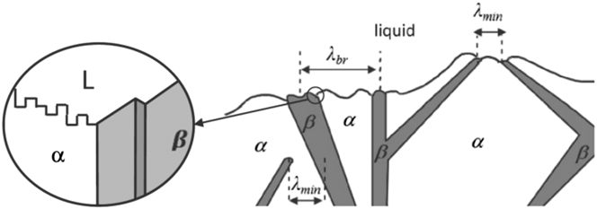
By contrast, a degenerate eutectic reaction proceeds with little to no cooperation between the phases, and the eutectic spacing varies. This situation occurs when one of the two phases grows faster than the other. Consequently, the growth mechanism of the single “leading” phase determines the structure of the eutectic. Such is the case in semimetallic eutectics wherein one of the two phases is faceted (e.g., Si or β in Fig. 1) while the other is nonfaceted (e.g., Al or α in Fig. 1). The faceted phase possesses a certain stiffness due to the nature of its covalent bonding and thus is only capable of growing along well-defined, “fast growth” directions.Reference Kurz and Fisher2,Reference Napolitano, Meco and Jung4,Reference Shahani, Xiao and Voorhees5 In these directions, the faceted phase grows with the assistance of defects such as twin boundaries and screw dislocations. Detailed analysis of the total undercooling of the eutectic growth front by Kurz and Fisher in 1980 shows that the faceted phase leads the growth process, i.e., it has lower undercooling and extends deeper into the melt.Reference Fisher and Kurz6 Thus, the eutectic growth front is nonisothermal (see also Fig. 1 for a schematic illustration).
Growth mechanism of an unmodified, degenerate α–β eutectic into a liquid (L) phase. The α consists of nonfaceted, solid–liquid interfaces, whereas the β phase is fully faceted (see the inset). A difficulty in smoothly changing the growth direction of the faceted β phase results in the zig-zag structure. Twin defects facilitate its continued propagation. Figure reprinted with permission from Springer Nature.Reference Stefanescu7
B. Modification of degenerate eutectics
The brittleness of the coarse and faceted Si crystals in untreated Al–Si eutectics is the main reason for its poor mechanical properties, such as premature crack initiation and fracture in tension.Reference Steen and Hellawell8–Reference Hosch and Napolitano10 However, to our advantage, the growth mechanism of the faceted phase is fairly complex, and thus its microstructure (as well as that of the overall eutectic) can be influenced in various ways. One option is to tune the solidification parameters, e.g., growth velocity and thermal gradient, in directional experiments.Reference Napolitano, Meco and Jung4,Reference Hosch, England and Napolitano23 The resulting microstructure can vary from flake-like to fibrous depending on the growth conditions and the volume fractions of the constitutive elements, see Refs. Reference Dantzig and Rappaz3, Reference Croker, Fidler and Smith11, and Reference Elliott12 for further details. A second route is to tune the alloy chemistry by introducing trace concentrations of a metallic element, a process known as chemical modification.
In 1921, Aladar Pacz was granted a US patent for the discovery that the treatment of Al–Si alloys containing between 8 and 15% Si (i.e., near the eutectic composition) with alkali fluoride flux before casting into the finished form yields improved tensile strength and ductility.Reference Pacz13 Pacz wrote of the modified alloy, “If now the metal be cast, it will be found that the fracture instead of being coarse, dark, and glassy, is fine-grained, light and dense. The physical properties have undergone a most remarkable change, the tensile strength rising to a point between 23,000 and 2788 pounds per square inch [from 15,000 to 18,000 pounds per square inch] and the elongation to a point between 3.5 to 6.25% [from 0.5%].”Reference Pacz13 Although Pacz’ discovery of eutectic modification predates the Second World War, it was not until after the War had ended that dramatic advancements in the aluminum casting industry were made. The booming aerospace industry in the 1960s provided the necessary stimulant for the production of new, light-weight aluminum alloys that complied with engineering requirements. Similarly, the energy crisis of the early 1970s inspired the replacement of heavy cast iron and steel with light-weight aluminum alloys. Many of these aluminum-based components were castings, among which Al–Si alloys constituted ∼90% of the total parts produced.Reference Wang, Lu and Kleperis14 Since then, chemical modification of this alloy has been widely practiced in the aerospace and automotive sectors as a viable route to enhance the mechanical properties of Al–Si castings. For instance, additions of only a few hundred ppm of Sr or Na are more than sufficient to modify the eutectic Si microstructure in Al–Si castings from coarse flake-like into fine fibrous; such microstructural changes have favorable effects on both strength and ductility.Reference Yilmaz and Elliott9,Reference Mondolfo15 The critical levels of modifier necessary to produce significant changes in the microstructure are addressed in Sec. II below.
The remainder of our review is concerned with the types and mechanisms of this chemically induced modification. More specifically, we will address the following two questions: (i) What are the microstructural signatures commonly associated with modification; and (ii) Where do these signatures come from? As will be shown in Sec. II, chemical modification carries many connotations, depending in part on the perspectives of the beholder. Furthermore, as described in Sec. III, modification may originate during solidification (i.e., nucleation and growth of the eutectic phases) and/or subsequent annealing of the cast alloy. Finally, in Sec. IV, we will address challenges and future developments needed to move the field forward.
II. THE SIGNATURES OF MODIFICATION
The effects or signatures of modification are multifold. As alluded to in the previous paragraph, chemical modifiers may (i) alter the length-scale of the eutectic microstructure. More specifically, modification results in a structural refinement, i.e., a decrease in the average interlamellar spacing  $\bar{\lambda }$. It is important to re-iterate that refinement can also be achieved by solely increasing the growth velocity v in directional solidification experiments since ${\bar{\lambda }^2}v = {\rm{const}}{\rm{.}}$ according to the generalized Jackson–Hunt model.Reference Kurz and Fisher2,Reference Dantzig and Rappaz3,Reference Jackson and Hunt16 Chemical modifiers may also (ii) change the morphology of the faceted phase from flake-like to fibrous, see Fig. 2. The fibrous form of Si in modified Al–Si alloys minimizes stress concentration effects and therefore improves ductility substantially.Reference Shivkumar, Wang and Apelian17 Such morphological transitions are thought to be related to (iii) changes in the defect density. That is, the increased flexibility of the growth habit in the modified eutectic is made possible by a very high frequency of multiple twinning in the Si phase. For instance, Hellawell has reported that the twinning probability in Sr-, Ba-, Ca-, and Yb-treated eutectics—defined as the ratio of the twin spacing to the Si{111} interplanar spacing—is two to three orders-of-magnitude higher than in the unmodified Al–Si casting.Reference Lu and Hellawell61 However, experimental evidence by other groups has been put forward that contradicts this claim and suggests instead that twins are not present in the modified structure.Reference Fredriksson, Hillert and Lange18 These opposing viewpoints are expounded in detail below. It is also well known that trace metal additions are accompanied by (iv) increased porosity in the casting, such that it negates any of the beneficial refining (i) or morphological (ii) effects discussed above.Reference Campbell and Tiryakioğlu19,Reference Sigworth20 Some investigators have found the porosity so detrimental that they have abandoned chemical modification of Al–Si eutectics.Reference Campbell and Tiryakioğlu19,Reference Sigworth20 Finally, chemical modifiers may (v) alter the topology (i.e., connectivity) of the eutectic phases, as first deduced from three-dimensional tomographic reconstructions by Moniri et al.Reference Moniri, Xiao and Shahani21 Whereas unmodified eutectics contain a network of interconnected Si flakes,Reference Shahani, Xiao and Voorhees5 its modified counterpart consists of isolated domains of Si that are surrounded by Al. This topological transition occurs (for the same volume fractions of Si and Al) because the nonfaceted phase leads at the solidification front in the modified alloy, and eventually engulfs the faceted phase in its wake.Reference Moniri, Xiao and Shahani21 In all, modification brings about a host of changes in the eutectic microstructure, including length-scale, morphology, defect density, porosity, and topology.
(a) Schematic representation of the different eutectic Si morphologies attained with varying degrees of chemical modification. In the unmodified or “chill cast” alloy, Si takes the form of coarse flakes; on the other hand, in the completely modified or “Na treated” alloy, Si is typically found as fine fibers. Reprinted with permission from American Welding Society.Reference Cross and Olson22 Example high-resolution scanning electron images corresponding to the (b) unmodified and (c) modified microstructures shown in (a). In both cases, the Al-rich phase has been chemically removed. (b) Adapted with permission from Springer NatureReference Hosch, England and Napolitano23 and (c) with permission from Elsevier.Reference Makhlouf and Guthy24
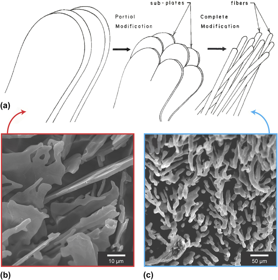
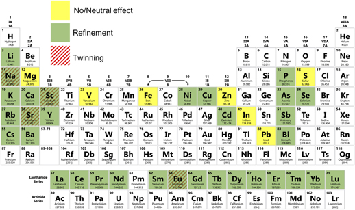
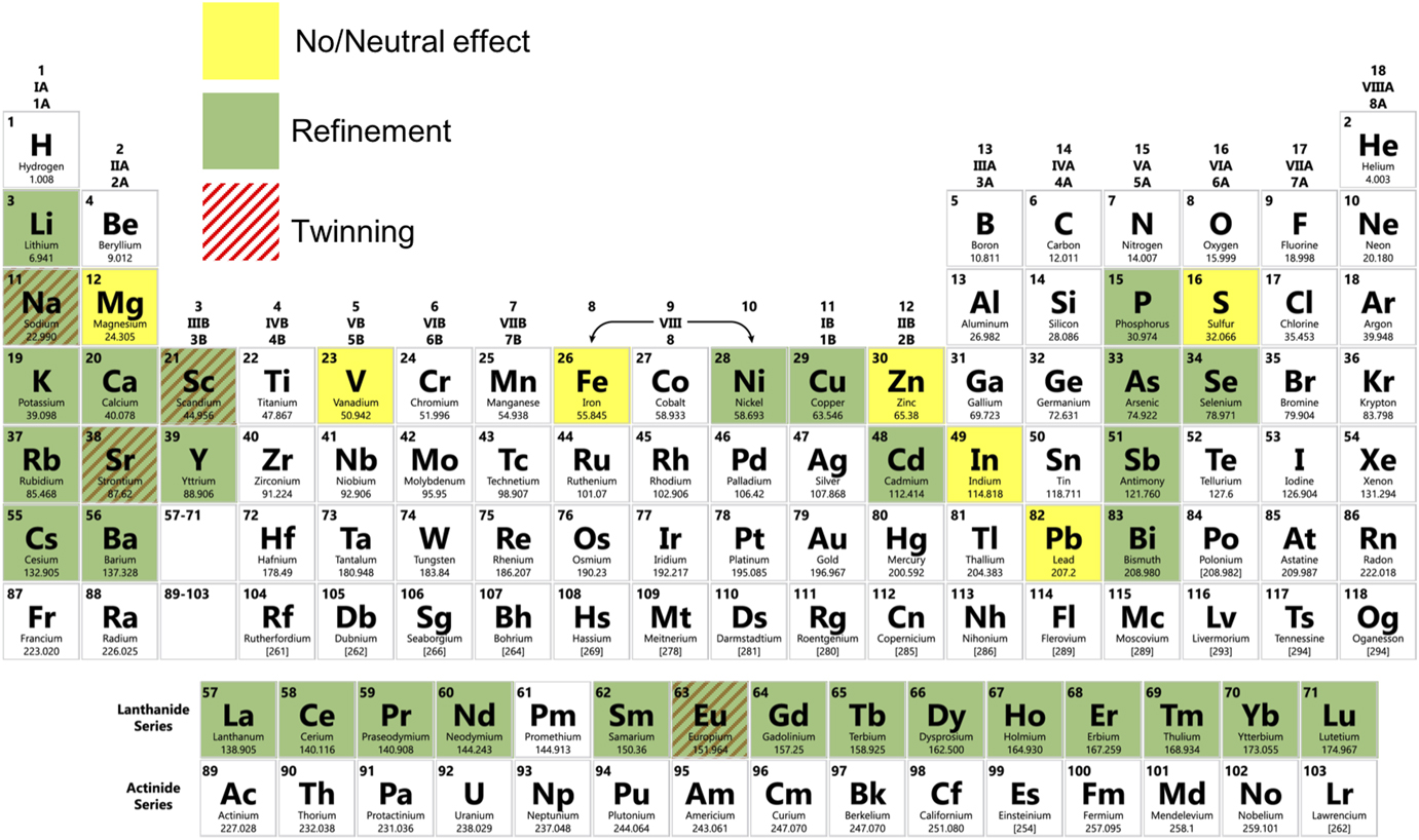
Figure 3 illustrates the potency of various elements for the modification of eutectic Si in Al–Si alloys, using data published in the literature in the period from May 1963 to May 2018.Reference Liang and Schmid-Fetzer25–Reference Dahle, Nogita, McDonald, Dinnis and Lu46 We note that “modification” is not always uniquely defined in the community (see also Section I.B), so we attempt to avoid any potential ambiguity by designating whether a particular modifying agent brings about only refinement and/or morphological change, or whether an increased density of twins is also observed. Due to these inconsistencies, we believe that it would be instructive for the community to agree upon a specific metric for reporting “modification”. Figure 3 is intended to provide a bigger picture of which elements have been used to modify eutectic Si in Al–Si alloys, and to what extent. It is evident that a vast majority of Group I and II, Lanthanides, and the nitrogen family (Group 15) elements cause refinement and morphological change. A few transition metals have also been reported to cause refinement/morphological change. Of note is that only a limited subset of all the elements investigated have been reported to also cause an increase in twinning, namely, Na, Sr, Sc, and Eu. Some elements have been reported to have neutral effect on modification. The reason for the varying degree of modification—from none for some elements, to morphological for most, and crystallographic for only a few—remains to be determined.
Summary of the modification potency of elements for eutectic Si in Al–Si alloys from the literature in the period from May 1963 to May 2018. Elements that bring about only a morphological change and/or refinement are shaded green, while those that also induce twinning are hatched with red lines. Elements that have been found to be neutral are illuminated as yellow. Data compiled from Refs. Reference Liang and Schmid-Fetzer25–Reference Dahle, Nogita, McDonald, Dinnis and Lu46.
III. THE ORIGINS OF MODIFICATION
A. Modification during nucleation
The first school of thought on the origins of modification concerns eutectic nucleation, and particularly that of the faceted phase (e.g., Si). In the mid-1960s, Crosley and Mondolfo conducted pioneering metallographic investigations on nucleation phenomena in Al–Si alloys.Reference Crosley and Mondolfo47 Their conclusions were 2-fold: (i) Eutectic Al is not affected by trace metal additions, while nucleation of eutectic Si is highly sensitive to the type and amount of modifiers present. In commercial unmodified alloys, eutectic Si is most likely to be nucleated by AlP particles that pre-exist in the melt. That is, the critical undercooling required for the nucleation of eutectic Si by the primary α (Al) phase is higher than that by the AlP particles. We note that P is an unavoidable trace element in Al–Si castings. (ii) Modification of Al–Si by Na results in a “neutralization” of the AlP particles such that easy nucleation of Si is prevented. The evidence for the latter effect is manifested in a depression of the critical nucleation temperature for eutectic Si in cooling curves of the Na-modified alloy. The undercooling required for Si nucleation in the presence of Na was recorded as 6–12 °C, versus 5–7 °C in the unmodified, hypoeutectic Al–Si alloy.Reference Crosley and Mondolfo47
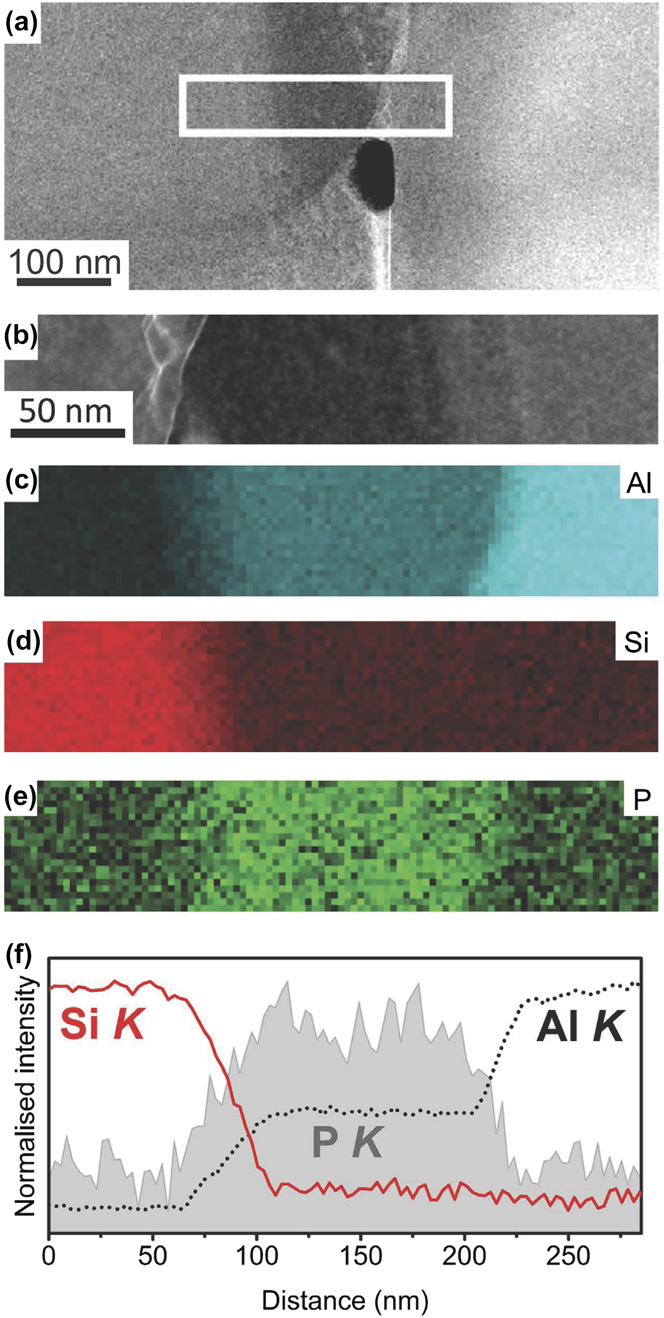
Support for Crosley and Mondolfo’s theory of modified nucleation comes from the recent body of work by Dahle and coworkers.Reference Dahle, Nogita, McDonald, Dinnis and Lu46,Reference McDonald, Nogita and Dahle48 Through electron backscatter diffraction (EBSD) of the solidified specimens, they determined that the eutectic Al shares an epitaxial relationship to the primary α (Al) dendrites in unmodified Al–Si alloys, while in Sr- and Sb-modified alloys, the eutectic Al has multiple orientations unrelated to the surrounding dendrites.Reference Dahle, Nogita, McDonald, Dinnis and Lu46 This suggests independent nucleation and growth in the Sr- and Sb-modified alloys. Moreover, Dahle and coworkers detected AlP particles located at the center of polyhedral Si. Selected area diffraction patterns in the transmission electron microscope (TEM) show that there is no lattice mismatch between the (111) planes of AlP and the Si crystal. The authors took this result to mean that AlP is a good nucleant for eutectic Si.Reference Dahle, Nogita, McDonald, Dinnis and Lu46 Both AlP and Si have cubic crystal structures with nearly identical lattice parameters (5.421 ÅReference Straumanis and Aka49 and 5.431 Å,Reference Yeh, Lu, Froyen and Zunger50 respectively). The modification of the Al–Si alloy is then thought to be due to the fact that the AlP nuclei are saturated with Sr-containing intermetallics, e.g., Al2Si2Sr; this contributes to an increased “nucleation difficulty” for eutectic Si (i.e., higher nucleation undercooling and also lower nucleation frequency).Reference Dahle, Nogita, McDonald, Dinnis and Lu46 Further high-resolution evidence was provided by Schumacher and coworkers.Reference Li, Hage, Liu, Ramasse and Schumacher51 They report that P, in the form of AlP particles, is located not only at the center of primary Si but also at the interface between eutectic Si and eutectic Al, see Fig. 4.Reference Li, Hage, Liu, Ramasse and Schumacher51 During the eutectic reaction, the AlP forms at the surface of Al, and thereby provides favorable conditions for the heterogeneous nucleation of eutectic Si on eutectic Al. Direct experimental verification showing the “poisoning” of these such particles by Sr or Na is still lacking. Nevertheless, it is clear that the potency of AlP as an innoculant must be critically considered in unmodified and modified Al–Si alloys alike.
(a and b) High-resolution HAADF STEM images; corresponding EELS maps of (c) Al, (d) Si, and (e) P; and (f) line scanning analysis of Al, Si, and P in an Al–18Si–0.03P mater alloy. The AlP particle was observed at the interface between Al and Si. Retrieved with permission from Macmillan Publishers Limited, part of Springer Nature.Reference Li, Hage, Liu, Ramasse and Schumacher51
At low concentrations of P, the AlP particles may also nucleate on oxide bifilms that are folded into the liquid phase, as suggested by Campbell and Tiryakioğlu and others.Reference Campbell and Tiryakioğlu19,Reference Pennors, Samuel, Samuel and Doty52 In the absence of any modifier species, the Si phase precipitates on these crumpled bifilms (decorated with the AlP particles). The planar growth of the Si phase straightens the bifilms, thereby creating cracks along the long axis of the Si particles. That is, the Si particles reflect the length of the straightened-out bifilms. From the preceding analysis, Sr deactivates the AlP nucleation sites and hence also the oxide bifilm as a growth substrate for Si. In modified alloys, then, the bifilms are no longer sequestered into Si particles and are now in free suspension in the liquid. To accommodate the solidification shrinkage upon freezing, the bifilm opens and a shrinkage cavity (pore) is initiated. This mechanism of porosity development in modified alloys is predicted by the fact that the oxide bifilm is a double film, unbonded between its two halves.Reference Campbell and Tiryakioğlu19
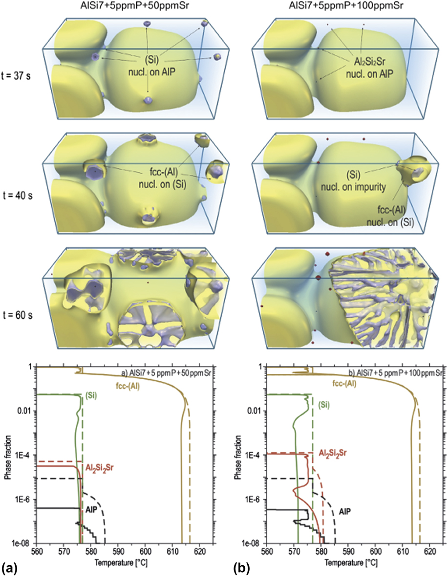
Through phase-field (PF) simulation linked to CALPHAD databases, Eiken et al. showed that critical threshold amounts of P and Sr are needed for the pre-silicon formation of AlP and Al2Si2Sr, respectively.Reference Eiken, Apel, Liang and Schmid-Fetzer45 The threshold for P was found to be between 3.2 and 3.8 ppm, where the lower-bound was obtained from PF simulations due to the additional consideration of nucleation undercooling. Thus, the minimum P level to form AlP is indeed well below the commercial purity standards of Al–Si alloys. Meanwhile, thermodynamic calculations revealed a critical Sr threshold of approximately 80 ppm to form Al2Si2Sr. In corresponding PF simulations with subcritical Sr levels [Fig. 5(a)], AlP was not neutralized by Al2Si2Sr, and thus eutectic Si nucleated with high frequency on AlP with minimal undercooling.Reference Eiken, Apel, Liang and Schmid-Fetzer45 The solidification pathway for supercritical Sr levels [Fig. 5(b)] is notably different: Al2Si2Sr poisons the AlP particles, which results in a retarded nucleation of eutectic Si. Moreover, the nucleation frequency was found to be significantly less (e.g., one nuclei in the modified alloy versus four per unit volume in the unmodified alloy, see Fig. 5).Reference Eiken, Apel, Liang and Schmid-Fetzer45 The refinement and structural modification of the eutectic Si lamellae result from this reduced nucleation rate and will be dealt with below.
PF simulation results for solidification in AlSi7 + 5 ppm P with two different Sr contents: (a, left column) 50 ppm Sr, and (b, right column) 100 ppm Sr. The first three rows show different time-steps during the microstructural evolution. In (a), eutectic Si nucleated on AlP and grew as plates while in (b) Al2Si2Sr first nucleated on AlP, deactivating the nucleation sites of Si. The latter forms at higher growth undercooling in a fibrous morphology. The bottom row shows the phase fractions versus temperature, evaluated from PF (solid lines), and Scheil prediction (dashed lines) for both alloy compositions. Figures adapted with permission from Elsevier.Reference Eiken, Apel, Liang and Schmid-Fetzer45
It should be mentioned that the details surrounding the influence of the modifier species on the nucleation rate are not universally agreed upon. According to Liao and coworkers, the decrease of nucleation temperature in modified alloys only suggests that the required nucleation undercooling is increased.Reference Liao, Zhang, Wu, Wang and Sun53 In other words, the addition of the Sr modifier species makes the nucleation process more difficult at higher temperatures. Liao and coworkers comment that the driving force for nucleation increases with the Sr content, and in addition, “other nucleation sites are activated, although they do not have the power to operate at higher temperatures.”Reference Liao, Zhang, Wu, Wang and Sun53 Consequently, the higher driving force and the operation of these nucleation sites actually leads to an increased rate of nucleation of the modified eutectic. Thus, the number of nuclei per unit volume per unit time increases with respect to the unmodified alloy. Support for this alternative viewpoint comes from micrographs showing eutectic grain refinement in Al–Si alloys containing Sr and B.Reference Liao, Zhang, Wu, Wang and Sun53 Furthermore, not all modifier elements impact the nucleation rate in the same way: For instance, StJohn and coworkers demonstrated that Cu and Mg increased the nucleation density of Al–Si eutectic grains in unmodified and Sr-modified alloys, whereas Fe decreased the nucleation density in the same master alloys.Reference Darlapudi, McDonald, Terzi, Prasad, Felberbaum and StJohn54
What is the influence of the modified nucleation density (either positive or negative) on the resultant Si morphology? In the early 1980s, Flood and Hunt provided one of the pioneering attempts to answer this question.Reference Flood and Hunt55 They reasoned that for a given rate of heat extraction, the factor controlling the growth velocity of the eutectic is the solid–liquid interfacial area, which is directly controlled by the nucleation frequency. For a constant rate of heat extraction  $\dot{q}$, the growth velocity v will vary inversely with the total solid–liquid surface area A of the system. That is, $\dot{q} = vA{L_{\rm{f}}}$, where L f is the latent heat of fusion per unit volume. Therefore, the more eutectic grains that nucleate, the larger the interfacial area A and the lower the growth velocity v.Reference Flood and Hunt55 In the context of Fig. 5, then, this analysis indicates that growth velocities are higher in the Sr-modified alloy. Additionally, due to kinetic roughening,Reference Sunigawa56 Si tends to be nonfaceted at these higher velocities. Flood and Hunt proposed that the morphological transition from plate-like to fibrous Si occurs at the same time as the transition from faceted to nonfaceted growth.Reference Flood and Hunt55 However, Dahle and coworkers argued that the increase in velocity in the Sr-modified alloy is not large enough to induce the flake–fiber transition in Si.Reference McDonald, Dahle, Taylor and StJohn57
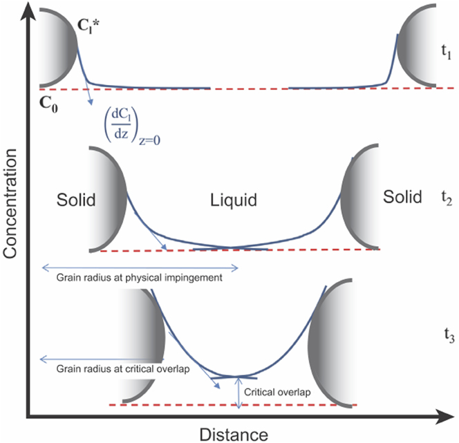
An alternative explanation has been put forth by StJohn and coworkers to explain the influence of nucleation density on the Si morphology in chemically modified alloys.Reference Darlapudi, McDonald, Terzi, Prasad, Felberbaum and StJohn54 During the growth of a eutectic grain, the modifier species is rejected by both eutectic phases into the melt and gradually piles up ahead of the solid–liquid interface. This solute segregation results in the formation of a constitutionally undercooled zone. The constitutional driving force for growth is related to the solute concentration gradient ahead of the interface, dC l/dz, where C l is the liquid concentration and z is the distance.Reference Kurz and Fisher2 Such constitutional effects in modified alloys can be better understood by considering Fig. 6: As two solid eutectic grains grow toward each other, their solute fields overlap and thus the constitutional driving force for growth decreases. After the driving force begins to decrease, the velocity decreases to a value where the Si morphology changes from fibrous to flake-like. This occurs at a point referred to as the “critical overlap” (see Fig. 6).Reference Darlapudi, McDonald, Terzi, Prasad, Felberbaum and StJohn54 Thus, a decrease in the spacing of nuclei (due to a high nucleation rate) causes the solute fields to overlap sooner. In this case, a higher proportion of eutectic grains grow with a fibrous morphology.Reference Darlapudi, McDonald, Terzi, Prasad, Felberbaum and StJohn54
Schematic illustration showing changes in the concentration gradient (and hence the constitutional supercooling) as two solid eutectic grains impinge on one another during solidification.  $C_1^*$ is the equilibrium liquid concentration at the interface (∗), C 0 is the far-field liquid concentration, z is the distance, and t is the time. At time-step t 1, the diffusion fields of the solids do not overlap. Eventually, the diffusion fields overlap, see time-step t 2. Finally, at time-step t 3, solute accumulation in the overlap region attains a critical value at which the growth velocity decreases to trigger the morphological change to flake-like Si. Figure adapted with permission from Elsevier.Reference Darlapudi, McDonald, Terzi, Prasad, Felberbaum and StJohn54
B. Modification during growth
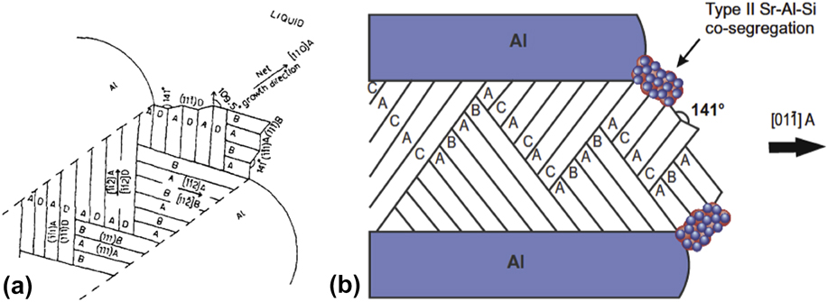
The second school of thought contends that the modifier species influences growth and not nucleation of the eutectic phases. Among the various “modified growth” theories that have been proposed from the 1960s and onwards, the three that have gained the most traction are (i) the twin plane re-entrant edge (TPRE) mechanism,Reference Wagner58,Reference Hamilton and Seidensticker59 (ii) the poisoning of the TPRE mechanism,Reference Day and Hellawell60 and (iii) impurity-induced twinning (IIT).Reference Lu and Hellawell61 These three mechanisms are thought to be valid under different growth conditions. For instance, at slow cooling rates in unmodified alloys, the TPRE mechanism becomes activated and the Si lamellae assume a plate-like morphology with closely spaced twins aligned parallel to the longer axis. Detailed reviews of TPRE and its variants can be found elsewhere,Reference Shahani, Gulsoy, Poulsen, Xiao and Voorhees62,Reference Shahani and Voorhees63 but the key idea is that the growth of new layers of the crystal occurs preferentially at the re-entrant edges, i.e., where the twin boundary intersects the solid–liquid interface. The first account of TPRE was described in faceted Ge dendrites by Wagner and Hamilton and Seidensticker in 1960.Reference Wagner58,Reference Hamilton and Seidensticker59 It is worth mentioning that TPRE also occurs in chemically modified alloys, although the twins are no longer parallel to the long axis: According to Shamsuzzoha and Hogan’s viewpoint [Fig. 7(a)], the twins marked AB in the bottom left give rise to branches in the form of twins BC.Reference Shamsuzzoha and Hogan64 Further branching produces AB twins on the surface marked C. This process of multiple twinning perpetuates and generates the entire Si fiber, which grows in a net [001] direction.Reference Shamsuzzoha and Hogan64 Based on the observations of Wagner and Hamilton and Seidensticker, as well as the concept of surface adsorption, Day and Hellawell advanced the poisoning of the TPRE mechanism in 1968.Reference Day and Hellawell60 It was assumed that the modifier retards Si growth by adsorbing at the re-entrant edges, thereby deactivating the TPRE mechanism and forcing the Si to grow in a more isotropic manner. Finally, in 1987, Li and Hellawell proposed that the modifier atoms are adsorbed on the {111} step-surfaces of Si, and the associated change in the stacking sequence facilitates the formation of frequent crystallographic twins, a process they termed IIT.Reference Lu and Hellawell61 The IIT mechanism makes two key assumptions: (i) the faceted phase has an FCC crystal structure; and (ii) only modifier elements that meet the ‘ideal’ atomic radius ratio r i/r ∼ 1.646 enable twin formation. Here, r i is the atomic radius of the modifier element and r is that of the faceted phase. The arguments made by Lu and Hellawell to reach this conclusion were purely geometric. Yet some elements that do not satisfy this criterion (e.g., Sr and Na) still modify the eutectic Si microstructure to a significant extent by increasing the twin density (see Fig. 3). Thus, there are likely other factors beyond atomic radius that are critical for modified growth. Taken altogether, both poisoning of TPRE and IIT involve modifier adsorption on Si at the growth front; however, the two mechanisms differ in two important aspects: (a) the location of interfacial poisoning (i.e., re-entrant grooves versus facet planes), as well as (b) the consequence of it (twin suppression versus twin formation).
(a) Schematic of a fully modified Si fiber with an effective [110] growth axis in the Al–14% Si–0.18% Sr alloy. The fiber contains intersecting twins with re-entrant edges in contact with the liquid phase. (b) These edges are “poisoned” by Sr–Al–Si (type-II) co-segregations that prevent the attachment of Si to the growing fiber. (a) Reprinted with permission from Taylor and FrancisReference Shamsuzzoha and Hogan64 and (b) with permission from Elsevier.Reference Timpel, Wanderka, Schlesiger, Yamamoto, Lazarev, Isheim, Schmitz, Matsumura and Banhart68
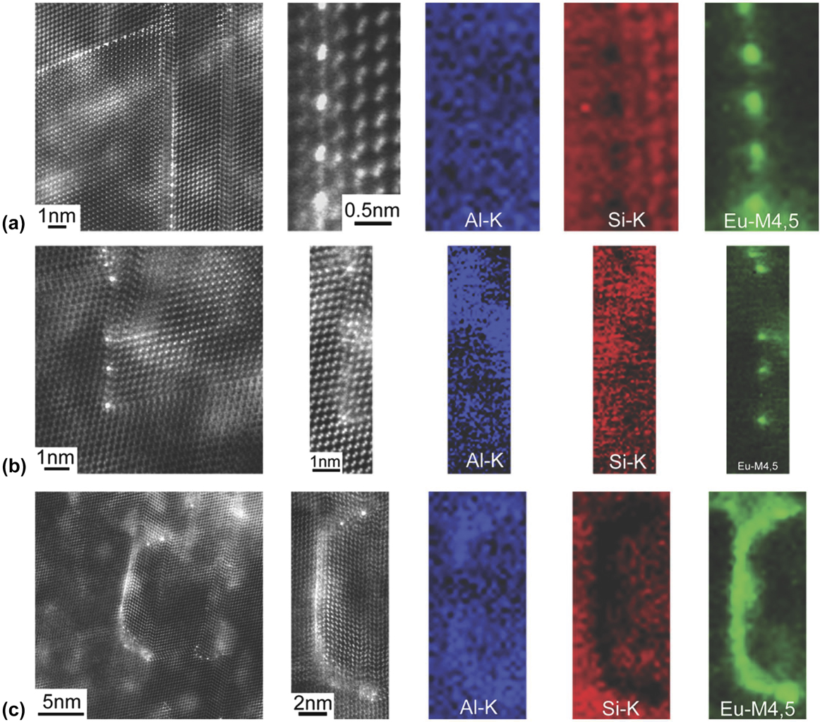
Recently, Schumacher and colleagues have found direct experimental support for the poisoning of TPRE and the IIT mechanisms through high-resolution high angle annular dark field (HAADF) scanning transmission electron microscopy (STEM).Reference Li, Hage, Wiessner, Romaner, Scheiber, Sartory, Ramasse and Schumacher65 Their results on the diverse roles of trace Eu additions on the growth of eutectic Si in Al–Si alloys are summarized in Fig. 8. In some cases (see top row), Eu atoms are located approximately between every two Si atomic columns at the TPRE. These images point to the poisoning of the TPRE mechanism. DFT calculations performed by the same team show that structures with mixed Eu–Si occupation at the twin boundary, akin to Fig. 8(a), are energetically preferred (i.e., they possess a more negative segregation energy compared to other configurations).Reference Li, Hage, Wiessner, Romaner, Scheiber, Sartory, Ramasse and Schumacher65 On the other hand, Eu atoms can also be located at the intersection of Si facets and twins (see middle row), thereby suggesting that the IIT mechanism is also operative. Finally, Schumacher and colleagues observed the entrainment of continuous layers of Eu within Si (bottom row). The authors propose that during solidification of eutectic Si, Al and Eu will segregate ahead of the growth front (the partition coefficients k Al < 1 and k Eu < 1); during continued growth, the {111} planes of Si fold on each other, resulting in solute impingement and entrainment of the segregation fields.Reference Li, Hage, Wiessner, Romaner, Scheiber, Sartory, Ramasse and Schumacher65,Reference Li, Albu, Hofer and Schumacher66 No significant twinning was observed in the Si phase adjacent to the entrained Eu layer, indicating that this layer did not result from either the poisoning of TPRE nor the IIT mechanisms.
High resolution HAADF STEM images and EELS maps of Al, Si, and Eu in an Al–5Si–0.05Eu alloy: (a) Eu atoms are located at the TPRE, indicating that poisoning of the TPRE mechanism is active; (b) Eu-rich atomic columns are located at the intersection of Si facets and twins, indicating that the IIT mechanism is active; (c) Eu atoms are located in a continuous Eu-rich layer, indicating that a solute entrainment occurs within eutectic Si. See text for descriptions of each mechanism. Retrieved with permission from Macmillan Publishers Limited, part of Springer Nature.Reference Li, Hage, Wiessner, Romaner, Scheiber, Sartory, Ramasse and Schumacher65
The poisoning of the TPRE mechanism has also been used recently to explain the EBSD results of Liu et al. on a Sr-modified Al–Si alloy.Reference Liu, Zhang, Beausir, Liu, Esling, Yu, Zhao and Zuo67 The authors suggested that modification via poisoning can occur in two distinct ways: Sr can block the Si growth on one initial {111} twin plane and force the formation of (i) new twins with the same misorientation and inclination as the first, or (ii) new twins with different orientations and inclinations. The latter scenario leads to a change in the growth direction, resulting in a more isotropic growth and thus the appearance of “quasi-equiaxed” Si crystals.Reference Liu, Zhang, Beausir, Liu, Esling, Yu, Zhao and Zuo67 The authors suppose that due to this Sr-induced deceleration of the Si crystal in the original growth direction, the growth velocities of both eutectic phases become comparable, i.e., Si no longer leads at the growth front. However, this conclusion is impossible to verify through ex situ experimental probes like EBSD. To conclusively determine the structure of the solid–liquid interfaces, one would require nondestructive and 3D imaging of eutectic solidification as it proceeds in real-time. To meet this need, Moniri and coworkers have illustrated through in situ X-ray tomography that the retardation is indeed more dramatic than predicted by Liu et al. The growth velocities are not comparable; instead, it is the eutectic Al phase that leads at the growth front, such that steady-state coupled growth between the eutectic phases can no longer be maintained.Reference Moniri, Xiao and Shahani21
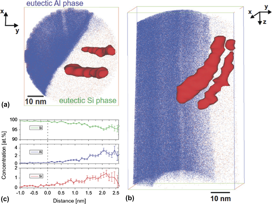
Growth modification may be due to not only single modifier atoms but also intermetallic compounds that pre-exist in the liquid phase, as first suggested by Banhart and coworkers in 2012.Reference Timpel, Wanderka, Schlesiger, Yamamoto, Lazarev, Isheim, Schmitz, Matsumura and Banhart68 Their atom probe tomography (APT) investigation revealed that the Sr modifier co-segregates with Al and Si within the eutectic Si phase, as well as at the eutectic Si/Al interface (Fig. 9).Reference Timpel, Wanderka, Schlesiger, Yamamoto, Lazarev, Isheim, Schmitz, Matsumura and Banhart68 Interestingly, the chemical compositions of the co-segregations derived from the APT proximograms [see, e.g., Fig. 9(c)] correspond to Al4Si33Sr and Al2Si88Sr, and not Al2Si2Sr as seen in previous investigations. Nevertheless, both of these former compounds have negative Gibbs free energies of formation at the Al–Si equilibrium eutectic temperature of 577 °C, suggesting that their existence at this temperature is thermodynamically plausible. Such co-segregations interact with the eutectic phases in two distinct ways: (i) By adsorbing at the Si {111} growth steps and promoting a change of stacking sequence of the propagating Si phase; and (ii) by adsorbing along the re-entrant edges and hence preventing a further attachment of Si atoms to the growing crystal.Reference Timpel, Wanderka, Schlesiger, Yamamoto, Lazarev, Isheim, Schmitz, Matsumura and Banhart68 The first possibility represents a revision of the IIT mechanism, where it is not Lu and Hellawell’s geometrical size factor that plays a major role in modification but rather the chemistry of the co-segregate.Reference Timpel, Wanderka, Schlesiger, Yamamoto, Lazarev, Isheim, Schmitz, Matsumura and Banhart68 Meanwhile, the latter scenario is a generalization of the poisoning of the TPRE mechanism and is depicted schematically in Fig. 7(b). Synchrotron-based X-ray nanodiffraction and X-ray fluorescence (XRF) elemental mapping have also been used to confirm the presence of intermetallic Sr phases in Sr-modified Al–Si alloys.Reference Manickaraj, Gorny, Cai and Shankar69 According to Schumacher and coworkers, such nanoscale co-segregates (clusters) are likely subcritical nuclei, and the local ordering of the melt would be that of fluctuating clusters.Reference Barrirero, Li, Engstler, Ghafoor, Schumacher, Odén and Mücklich70 Stable clusters would require heterogeneous substrates or high undercooling. Thus, during solidification of eutectic Si, two processes are dominant, that of (a) segregation of Sr and Al out of Si, and (b) heterogeneous nucleation of Sr–Al–Si clusters at the propagating Si growth front.Reference Barrirero, Li, Engstler, Ghafoor, Schumacher, Odén and Mücklich70 By contrast, one may view clusters only as an artefact of solute entrainment (described above), and not a leading cause of eutectic modification. Proponents of this viewpoint contend that elements such as Ca and Yb are commonly found in Al2Si2Ca and Al2Si2Yb phases, respectively, yet these elements do not necessarily modify the eutectic Si morphology.Reference Li, Albu, Hofer and Schumacher66 Whether it is single modifier atoms or modifier-containing clusters that induce the multiplication of crystallographic defects remains to be determined. However, both cases have in common the interaction between the modifier and eutectic Si during the growth process.
APT results of the eutectic Al/Si interface in an Al–10 wt% Si–0.1 wt% Fe alloy modified by 200 ppm Sr. (a) Top and (b) side views of 3D reconstruction of Sr (red) and Al (blue) atom positions in analyzed region-of-interest (ROI) of size 58 × 56 × 93 nm3. Si atoms have been omitted for clarity. The rendered isosurfaces represent 0.17 Sr atoms nm−1 in both views. (c) Proximogram showing Sr, Al, and Si concentration as a function of distance to the Si/Sr–Al–Si co-segregation interface. Figures reprinted with permission from Elsevier.Reference Timpel, Wanderka, Schlesiger, Yamamoto, Lazarev, Isheim, Schmitz, Matsumura and Banhart68
C. Modification during subsequent annealing
The last and most recent school of thought takes the view that eutectic modification occurs in the solid-state, i.e., following nucleation and growth and upon annealing of the fully solidified specimen.Reference Albu, Pal, Gspan, Picu, Hofer and Kothleitner71 This is the principal assessment of Kothleitner and coworkers, whose work is procedurally very similar to that of Schumacher et al.: The team used STEM together with DFT simulations to lend support to their theory of solid-state modification. Through STEM of a Sr-modified hypoeutectic Al–Si alloy, they observed that 〈110〉 interstitial Sr columns are located preferentially at the re-entrant groove of the twin boundaries.Reference Albu, Pal, Gspan, Picu, Hofer and Kothleitner71 Unlike the poisoning of the TPRE mechanism described above, however, Sr could not be detected along the twin defect in the  $\left\langle {1\bar{1}\bar{2}} \right\rangle$ growth direction.
Kothleitner and coworkers also performed ab initio DFT simulations to understand why Sr self-organizes into 〈110〉 interstitial columns and whether this configuration of Sr at the twin boundaries is energetically favorable. Figure 10 shows the variation in the system energy with distance between Sr atoms in the same column when aligned in several different crystallographic directions.Reference Albu, Pal, Gspan, Picu, Hofer and Kothleitner71 Both substitutional and interstitial Sr were considered. From these data, the team deduced that a binding energy between Sr atoms exists only when the column is aligned in the 〈110〉 direction. If Sr is substitutional, the strongest binding is in the second nearest-neighbor position; and if Sr is interstitial, the strongest binding occurs in the nearest-neighbor position and hence interstitial Sr columns are composed entirely of Sr.Reference Albu, Pal, Gspan, Picu, Hofer and Kothleitner71 This result corroborates their STEM findings mentioned above. The team also compared the system energies of (i) a Si lattice with two successive twins, (ii) the same structure with two 〈110〉 interstitial Sr columns located at the twin boundaries, and (iii) a perfect Si lattice without the twins but with the same Sr columns as in (ii). Out of the three cases, the energetic cost of (ii)—introducing a twin boundary and a Sr column located on it—was the lowest. This indicates that it is thermodynamically favorable for Sr to diffuse to a twin boundary, once the twin has already formed (presumably during solidification, i.e., a growth twin) and the Sr is located away from it. Conversely, the formation of a twin starting exactly from a Sr column is also thermodynamically favorable.Reference Albu, Pal, Gspan, Picu, Hofer and Kothleitner71 Despite the elegance of their DFT results, assessing whether such columns are kinetically likely to occur within eutectic Si requires further analysis of nucleation barriers, solid-state diffusion mechanisms, etc.
Variation of the system energy with distance between Sr atoms in the directions indicated in the legend. The vertical axis represents the excess energy above the pure Si lattice energy. This excess energy is scaled by the long-distance limit for each of the defects, which is 2.296 ± 0.072 eV for (a, top row) the interstitial case and 1.203 ± 0.100 eV for (b, bottom row) the substitutional case. Error bounds result from different k-point grids. The atomic configurations at right show the lowest energy states for interstitial (I) and substitutional (S) 〈110〉 Sr columns. Retrieved with permission from Macmillan Publishers Limited, part of Springer Nature.Reference Albu, Pal, Gspan, Picu, Hofer and Kothleitner71

IV. CHALLENGES AND OPPORTUNITIES
A. Outlook for experimental studies
External probes such as photons or electrons can be used to interact with matter in the eV and meV energy ranges, respectively, to gain insights that allow for characterizing and identifying materials. The proliferation of advanced characterization tools in recent years for ex situ nanoscale investigations of quenched modified eutectics has revealed some limitations of the classical models of modification and shed new light on the role of various modifier agents.Reference Li, Albu, Hofer and Schumacher66,Reference Timpel, Wanderka, Schlesiger, Yamamoto, Lazarev, Isheim, Schmitz, Matsumura and Banhart68,Reference Albu, Pal, Gspan, Picu, Hofer and Kothleitner71 Of relevance is electron energy loss spectroscopy (EELS), which provides the electronic fingerprint of the different constituents of a material and hence can provide atomically resolved mapping of the local composition within a sample.Reference Krivanek, Corbin, Dellby, Elston, Keyse, Murfitt, Own, Szilagyi and Woodruff72 For instance, in Eu-modified Al–Si alloys, Schumacher and coworkers observed nanoscale Al2Si2Eu intermetallic clusters or continuous Eu-rich layers located ahead of the Si twins via EELS (see above in Sec. III.B).Reference Li, Hage, Wiessner, Romaner, Scheiber, Sartory, Ramasse and Schumacher65 The authors also complemented the EELS maps with high-resolution STEM images that display the spatial distribution of Eu atoms in relation to the atomic columns of Si. Altogether, their results support the simultaneous occurrence of the IIT as well as poisoning of the TPRE growth mechanisms.
Given the typical concentrations (<100–1000 ppm) of modifying agents used in Al–Si alloys,Reference Sigworth20 the success of analytical methods to investigate the local spatial distribution of the modifying agent relies on some key factors: (i) the chemical identity (atomic number) of the modifier, (ii) the susceptibility of the modifier to electron-beam irradiation, and (iii) the resolution limit of the analytical method to be used (spatial and, if applicable, energy resolutions). Of significance among these factors is the chemical identity of the modifying agent. While Sr has been found to be amenable to a suite of analytical methods such as imaging (direct observation) via STEM,Reference Li, Albu, Hofer and Schumacher66,Reference Timpel, Wanderka, Schlesiger, Yamamoto, Lazarev, Isheim, Schmitz, Matsumura and Banhart68,Reference Timpel, Wanderka, Vinod Kumar and Banhart73 elemental analysis via X-ray energy dispersive spectroscopy (EDS),Reference Timpel, Wanderka, Schlesiger, Yamamoto, Lazarev, Isheim, Schmitz, Matsumura and Banhart68 and EELS in STEM (STEM-EDS, STEM-EELS), as well as XRF microscopy,Reference Nogita, Yasuda, Yoshida, Uesugi, Takeuchi, Suzuki and Dahle74 the detection of trace amounts of Na—first used by Pacz in 1921 and still among the most common modifier species—remains an experimental bottleneck. We note that of the two modifiers, Na is more potent as it produces more uniform fibrous structure at lower concentrations (typically 0.005–0.01%); meanwhile, Sr modification requires somewhat higher concentrations (0.01–0.02%).Reference Gruzleski75 Considering only the influence of the modifier species on growth (see Sec. III.B above), this behavior is to be predicted by the IIT mechanism. In other words, Na is predicted to produce more growth twins in Si as compared to Sr.Reference Lu and Hellawell61 Only recently was the distribution of Na atoms within eutectic Si in Al–Si observed by laser-assisted APT.Reference Li, Barrirero, Engstler, Aboulfadl, Mücklich and Schumacher76 Other considerations for electron microcopy-based techniques include the possible knock-on damage in light elements (e.g., Na) as well as susceptibility to electron-beam irradiation. Another way forward is in situ TEM studies of Al–Si alloys,Reference Eswara Moorthy and Howe77,Reference Schneider and Howe78 providing an alternative method to perform future solidification experiments with high chemical and spatial resolutions. Continuing advances in the design of analytical tools for high-resolution characterization of materials containing light elements as well as those prone to beam irradiation will aid further analysis of the atomic distribution of Na in future studies. Of note are recently developed STEM designsReference Sagawa, Hashiguchi, Isabell, Ritz, Simson, Huth, Soltau, Martinez, Nellist and Kondo79 with enhanced annular bright field, a new imaging technique that facilitates the observation of light elements in part by their ability to operate at accelerating voltages as low as 30 kV.
B. Outlook for computational studies
According to the adsorption-and-entrapment model for modified growth discussed in Sec. III.B, the solutal entrapment likely forms an aggregation of Al–Si–X within, as well as in the vicinity of, the eutectic Si phase. Assuming that the chemical composition of these Al–Si–X clusters can be determined using analytical methods, it would in principle be possible to also derive an estimate of the free energy of formation for these intermetallic compounds at the eutectic equilibrium temperature to rationalize their thermodynamic stability, as in Ref. Reference Timpel, Wanderka, Schlesiger, Yamamoto, Lazarev, Isheim, Schmitz, Matsumura and Banhart68. A plausible means to accomplish this task is to use the CALPHAD method, which provides a realistic thermodynamic assessment of alloys based on all available information on the phase equilibria and thermochemical properties of a given system. However, the free energy curves might only be defined over a finite range of composition that may not necessarily coincide with those investigated in solidification studies. Therefore, a problem arises in cases where the free energies of the phases become undefined or discontinuous. We note that, in the phase field community, methods have been recently reported that eliminate such characteristics while largely retaining the free energy values.Reference Jokisaari and Thornton80
Hecht et al. have reviewed the advances in phase field modeling of multiphase solidification.Reference Hecht, Gránásy, Pusztai, Böttger, Apel, Witusiewicz, Ratke, De Wilde, Froyen, Camel, Drevet, Faivre, Fries, Legendre and Rex81 Other reviewsReference Kulkarni, Kohanek, Tyler, Hanson, Kim, Thornton and Braun82,Reference LLorca and Orera83 and research articles,Reference Steinmetz, Hötzer, Kellner, Genau and Nestler84,Reference Zhang, Guo and Xiong85 as well as references therein, provide additional examples of how PF modeling and other theoretical methods can be used to understand the physical mechanisms controlling the microstructural development. However, in a phase field simulation, the interface is diffuse and thus the incorporation of interfacial energy anisotropy requires careful consideration. Such is the case for the eutectic Si constituent considered here, which forms sharp facets with a discrete set of orientations (below its roughening transition). When the anisotropic interfacial energy is sufficiently strong, the unregularized Cahn–Hilliard equations become ill-posed. To remove the ill-posedness, a number of regularization strategies have been introduced, see, e.g., Refs. Reference Eggleston, McFadden and Voorhees86 and Reference Torabi, Lowengrub, Voigt and Wise87.
V. CONCLUDING REMARKS
Since Pacz’ discovery of eutectic modification in 1921, several elements have been reported to induce varying degrees of modification (e.g., refinement, morphological change, and twinning; see Sec. II). Much of this research has been, and continues to be, motivated from both a scientific interest—establishing direct links between microscopic building blocks and macroscopic performance limits—and technological relevance—developing aluminum-based alloys for engineering applications.
Our current understanding of the process of eutectic modification by (metallic) species is largely based on the physical models developed from a geometric point of view (e.g., impurity-induced-twinning; see Sec. III.B). In these conventional pictures, the modifying agents of “optimum” radius (relative to the Si matrix) force a monolayer step to miss one regular close packed position, thereby altering the stacking sequence and creating or suppressing coherent Σ3 twin defects. While the above-discussed conventional mechanisms have, to a large extent, guided the field, recent reports on partially and fullysolidified specimens have provided great insights into the structure and crystallography of chemically modified degenerate eutectics. Furthermore, the rich variety of growth forms that are experimentally observed calls into question our conventional wisdom surrounding eutectic modification.
The emerging synchrotron X-ray imaging methods, which enable spatially and temporally resolved investigation of structural materials under relevant growth conditions, have displayed the capability to offer unprecedented insights into the growth forms of this and other classes of materials under relevant conditions.Reference Liotti, Arteta, Zisserman, Lui, Lempitsky and Grant88–Reference Falch, Casari, Di Michiel, Detlefs, Snigireva, Snigireva, Honkimäki and Mathiesen90 Key opportunities reside in integrating this and other relevant real-time imaging tools with advanced ex situ analytical methods (e.g., EELS; see Sec. IV.A) to draw direct comparisons against the unmodified alloys to elucidate conclusively the role of modifier species. Linking the microstructural and topological evolution, as measured recently in three dimensions,Reference Moniri, Xiao and Shahani21 to the crystallographic features of, as well as the local spatial distribution of the modifier atoms in, fully solidified samples can help move us closer to a unifying theory of chemical modification of degenerate eutectics.
Such insights can be readily extended to a vast array of other materials systems in which elemental modifiers play a critical role. An example is the additive manufacturing of technologically useful classes of alloys. It was recently demonstratedReference Martin, Yahata, Hundley, Mayer, Schafedler and Pollock91 that chemical modification of the feedstock alloy with grain refining nanoparticles for additive manufacturing can achieve previously incompatible high-strength aluminum alloys that are crack-free, equiaxed, and fine-grained. It is reasonable to assume that chemical modification by trace metal additions—a lesson from casting—can vastly expand the range of compatible metallic materials for future development of additively manufactured alloys, representing landscape-changing advances across multiple sectors such as aerospace, automotive, and biomedical.


 Open access

