


The most abundant and cleanest source of energy available on Earth, solar energy, is also the most underutilized. Its peak intensity is 1000 W/m2 which, averaged over space and time, provides vastly more energy daily than the global population consumes. Solar energy thus offers, in principle, a compelling option to power a sustainable and increasingly electricity-centric future.[Reference Markel, Mai and Kintner-Meyer1] While a substantial photovoltaic industry is beginning to take shape worldwide, driven by early generation solar technology based on silicon and compound semiconductors such as cadmium telluride, the fact remains that, in order to compete with traditional energy sources, particularly with cheap and plentiful natural gas, solar photovoltaic systems must cost, fully installed, no more than $1 per watt-peak, which translates to a levelized cost of electricity of approximately $0.05/kWh over a system lifetime.[2] This is noticeably less than current first- and second-generation commercially available solar products, which are held back by higher materials and manufacturing costs; combined with installation costs influenced by the bulky, heavy, and rigid nature of the solar panels themselves.
Third-generation photovoltaic systems, including organic, dye-sensitized, and colloidal quantum dot (CQD) solar cells, offer a path to low-weight, low-cost, and prospectively high-efficiency solar energy capture and conversion. While third-generation technologies currently function at lower efficiency than commercial first-generation modules, significant pathways exist to reach and surpass the conversion efficiencies required to be commercially feasible.
CQD solar cells are of particular interest among the mentioned technologies due to the size tunability of these nanometer-scale semiconductor particles, pictured in Fig. 1(a). The optimal bandgap for a single-junction solar cell as reported by Shockley and Queisser[Reference Shockley and Queisser4] is 1.1 eV; while this offers a limited selection of bulk semiconductors, the quantum confinement effect allows the fabrication of quantum dots (QDs) with reasonable properties[Reference Murray, Norris and Bawendi5] using bulk small bandgap semiconductor compounds such as lead sulfide (PbS) and lead selenide (PbSe). By adjusting synthesis parameters, the size, and therefore optical bandgap, of the QDs can be controllably varied across a wide spectral range.
(a) Scanning electron micrograph of as-synthesized QDs (top, adapted by permission from Macmillan Publishers Ltd: Ref. Reference Sargent3, copyright 2009), with schematic diagram of a single, uncapped QD (bottom); (b) the absorption spectrum of CQD films (bottom) can be matched to the power spectrum of sunlight reaching the Earth (top). Nanoparticles with a short-wavelength infrared bandgap can be shifted to blue wavelengths at the synthesis stage by ensuring that they have dimensions smaller than the Bohr exciton radius (ϕ) characteristic of their constituent semiconductor material (adapted by permission from Macmillan Publishers Ltd: Ref. Reference Sargent6, copyright 2012).
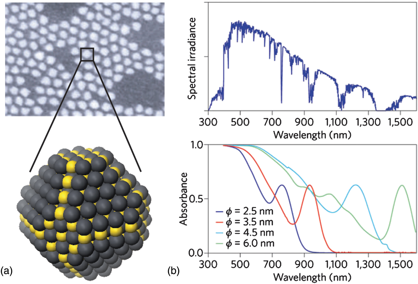
This size tunability is particularly powerful in realizing multi-junction solar cells [Fig. 1(b)]—devices with layers of two or more QD sizes that allow efficient collection of energy from the wide solar spectrum, including previously untapped infrared energy.[Reference Choi, Wenger, Hoffman, Lim, Luria, Jasieniak, Marohn and Hanrath7, Reference Wang, Koleilat, Tang, Liu, Kramer, Debnath, Brzozowski, Barkhouse, Levina, Hoogland and Sargent8]
Recent progress in performance and materials processing
CQDs are synthesized in solution and kept colloidally stable by capping the semiconductor surface with long passivating ligands.[Reference Alivisatos9] These long molecules are exchanged during device formation for shorter alternatives, bringing the dots closer to improve electrical transport while maintaining the quantum confinement effect.[Reference Yu, Wang and Guyot-Sionnest10] Using a solution-based colloidal semiconductor opens a wide array of fabrication methods and applications unavailable in conventional bulk semiconductors. CQD solar cells can be created using a variety of simple, inexpensive techniques, from small-scale spin coating, drop casting and dip coating[Reference Maenosono, Okubo and Yamaguchi11] to production-scale roll-to-roll processes[Reference Shaheen, Radspinner, Peyghambarian and Jabbour12] on flexible substrates. This further drives down the overall cost of the final product by providing a lightweight, versatile alternative to the traditional bulky modules, offering the prospect of lowered balance of system costs via reduced outlays associated with racking and installation.
Since the conception of infrared-capable CQD solar cells[Reference McDonald, Konstantatos, Zhang, Cyr, Klem, Levina and Sargent13] in 2005, the field has made rapid progress, improving from initial sub-1% to over 7% certified solar power conversion efficiencies[Reference Ip, Thon, Hoogland, Voznyy, Zhitomirsky, Debnath, Levina, Rollny, Carey, Fischer, Kemp, Kramer, Ning, Labelle, Chou, Amassian and Sargent14] in 2012. Major advances can be categorized into two broad headings: improvements in device architecture, wherein the best is made of the QD solid's available electronic materials properties by rational choice of electrodes and optimization of the overall materials stack for a joint optical and electronic perspective; and improvements in materials science and engineering, with the primary goal of improving the mobility of both electrons and holes, and minimizing excess recombination, within the QD solid.
In reference to progress in device architecture (Fig. 2), formative research in the field was carried out on the relatively simple Schottky architecture.[Reference McDonald, Konstantatos, Zhang, Cyr, Klem, Levina and Sargent13, Reference Koleilat, Levina, Shukla, Myrskog, Hinds, Pattantyus-Abraham and Sargent17–Reference Ma, Swisher, Ewers, Engel, Ferry, Atwater and Alivisatos22] Devices consist of a layer of p-doped QDs sandwiched between an Ohmic conductive transparent electrode such as indium tin oxide and a metal electrode with a shallow work function. In this layout, a Schottky junction is formed at the QD-to-metal interface, giving rise to charge separation via the formation of a depletion region with a built-in field that separates and drives out electrons and holes. This architecture suffers when, in an attempt to increase total light absorption, the thickness of the active layer is increased well beyond the thickness of the depletion region. In this case, the strongest rate of generation occurs in the undepleted quasi-neutral material, in which minority carrier diffusion proceeds inefficiently in today's CQD solids.[Reference Kramer and Sargent15]
Schematic diagrams of most significant CQD photovoltaic device architectures, each constructed on glass coated with a transparent conductive oxide (either indium tin oxide (ITO) or fluorinated tin oxide (FTO)). The Schottky cell, left, has a layer of p-doped CQD directly on the substrate, with a shallow work function metal (aluminum or magnesium) forming the top contact. The depleted heterojunction, middle, has a layer of mesoporous, n-doped titania between the substrate and the CQD layer, with a deep work function hole acceptor as the top electrode (either gold or molybdenum oxide). The quantum junction cell, right, employs layers of p- and n-doped QDs to form a p–n junction using one base material system. Schottky and depleted heterojunction figures adapted with permission from Ref. Reference Kramer and Sargent15, copyright 2011 American Chemical Society. Quantum junction figure adapted with permission from Ref. Reference Zhitomirsky, Furukawa, Tang, Stadler, Hoogland, Voznyy, Liu and Sargent16, copyright 2012 John Wiley and Sons.

The field addressed this limitation by designing architectures that shift the charge-separating interface closer to the source of illumination. The first and, to date, most efficient architecture designed is the depleted heterojunction,[Reference Ip, Thon, Hoogland, Voznyy, Zhitomirsky, Debnath, Levina, Rollny, Carey, Fischer, Kemp, Kramer, Ning, Labelle, Chou, Amassian and Sargent14, Reference Leschkies, Beatty, Kang, Norris and Aydil23–Reference Liu, Tang, Kramer, Debnath, Koleilat, Wang, Fisher, Li, Brzozowski, Levina and Sargent27] which flips the Schottky structure and layers the QDs atop a shallow work function, transparent electron acceptor such as titania or zinc oxide. The Ohmic contact is now formed at the back of the cell, the top electrode made using a deep work function metal or, most promisingly, a metal oxide such as molybdenum oxide. In a similar vein, the recently reported quantum junction architecture[Reference Tang, Zhitomirsky, Hoogland, Wang, Furukawa, Levina and Sargent28, Reference Liu, Zhitomirsky, Hoogland, Tang, Kramer, Ning and Sargent29] replaces the thick oxide electron acceptor layer of the depleted heterojunction with a p–n junction fully comprised of appropriately doped QDs. In this architecture, which relied on improved control of doping type and amplitude in QD solids,[Reference Zhitomirsky, Furukawa, Tang, Stadler, Hoogland, Voznyy, Liu and Sargent16, Reference Talapin and Murray30] light passes through a thin p-doped layer followed by a thicker n-doped film, with the desired charge separation occurring at the interface. Present-day performance records for each platform are outlined in Table I.
Current record performance metrics for the three main CQD photovoltaic architectures.
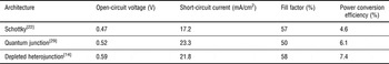
When one compares performance characteristics from Table I with theoretical performance limits, it is clear that today's best devices operate well below their inherent potential. Each of their open-circuit voltage; their short-circuit current; and their fill factor are 1.4–1.6 × lower than the optimum. Numerous research groups have worked to quantify these limitations, and consistently arrived at a similar conclusion: major further quantitative improvements in electronic transport are required to continue rapid progress for the field.[Reference Ip, Thon, Hoogland, Voznyy, Zhitomirsky, Debnath, Levina, Rollny, Carey, Fischer, Kemp, Kramer, Ning, Labelle, Chou, Amassian and Sargent14, Reference Koleilat, Levina, Shukla, Myrskog, Hinds, Pattantyus-Abraham and Sargent17, Reference Johnston, Pattantyus-Abraham, Clifford, Myrskog, MacNeil, Levina and Sargent18, Reference Clifford, Konstantatos, Johnston, Hoogland, Levina and Sargent31–Reference Talgorn, de Vries, Siebbeles and Houtepen36] Improved electronic transport must include, but also go well beyond, reporting higher carrier mobilities for charges of each type. Only once lifetime, determined by the presence of recombination centers, is also dramatically improved, can the sum of the diffusion length and drift length become comparable to, and ultimately exceed, the absorption length for light of all solar wavelengths of interest.
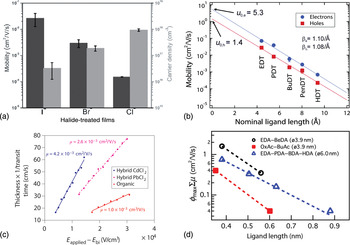
Figure 3 summarizes electrical transport characteristics for a number of different QD film systems. Figures 3(a) and 3(b) show mobility measurements for field-effect transistor (FET) architectures generated by the Sargent and Law groups, respectively. Mobility extracted in this manner does not correspond directly to carrier mobility in an active solar cell, since the properties of a transistor channel are quite distinct from the path traveled by carriers in a photovoltaic device. Further, in the FET mobility measurement, electronic trap states that can limit average mobility in an operating solar cell can be filled, and thus overcome, through gate-electrode control over the Fermi level in the transistor test structures. Nevertheless, this technique can be instructive in identifying promising ligands and treatments, and can be used as a comparative tool, as shown in both Fig. 3(a) (comparing mobilities for various inorganic ligands attached to PbS dots) and Fig. 3(b) (comparing mobilities for similar ligands of various lengths attached to PbSe dots). Figure 3(c) shows carrier mobility measured in a film of PbS QDs using various ligand capping techniques, measured instead using an optoelectronic time-of-flight technique. Figure 3(d) shows mobility measurements using a second optoelectronic method, time-resolved microwave conductivity, on PbSe QDs capped with ligands of varying length and a terminal functional group. The latter two techniques provide complementary insights into carrier dynamics within a working photovoltaic cell. The common trend across these various methods is that carrier mobilities are consistently several orders of magnitude lower than ultimately desired for long diffusion given that lifetimes that vary from the nanosecond to the microsecond regime in the best cases.
Carrier mobility values extracted for a variety of QD and ligand types, consistently showing low mobility: (a) mobility and carrier density measured using FETs composed of PbS QDs capped with halide ligands from tetrabutylammonium-chloride, -bromide, and -iodide. Reprinted with permission from Ref. Reference Zhitomirsky, Furukawa, Tang, Stadler, Hoogland, Voznyy, Liu and Sargent16, copyright 2012 John Wiley and Sons. (b) Mobility measured using FET layouts for PbSe QDs capped with dithiols of varying length (EDT, ethanedithiol; PDT, propanedithiol; BuDT, butanedithiol; PenDT, pentanedithiol; HDT, hexanedithiol), showing an inverse trend in mobility with increasing ligand length. Reprinted from Ref. Reference Liu, Gibbs, Puthussery, Gaik, Ihly, Hillhouse and Law32, copyright 2010 American Chemical Society. (c) Mobility measured by time-of-flight characterization for films of PbS QDs, some pre-exchanged with chloride ions, some used as-synthesized, all solid-state exchanged with mercaptopropionic acid. Reprinted from Ref. Reference Ip, Thon, Hoogland, Voznyy, Zhitomirsky, Debnath, Levina, Rollny, Carey, Fischer, Kemp, Kramer, Ning, Labelle, Chou, Amassian and Sargent14. (d) Mobility measured using time-resolved microwave conductivity (TRMC) on films composed of PbSe QDs capped with a variety of ligands of different lengths and terminal functional groups. Reprinted with permission from Ref. Reference Gao, Aerts, Sandeep, Talgorn, Savenije, Kinge, Siebbeles and Houtepen33, copyright 2012 American Chemical Society.
Long-chain ligands facilitate solution processing by allowing consistent, stable dispersions of capped QDs in low boiling point non-polar solvents such as octane or toluene; however, in a deposited film, the length of the capping molecule greatly increases the spacing between individual QDs.[Reference Ip, Thon, Hoogland, Voznyy, Zhitomirsky, Debnath, Levina, Rollny, Carey, Fischer, Kemp, Kramer, Ning, Labelle, Chou, Amassian and Sargent14, Reference Liu, Gibbs, Puthussery, Gaik, Ihly, Hillhouse and Law32] There is some debate in the field surrounding the nature and mechanism of electronic transport between QDs;[Reference Talapin, Lee, Kovalenko and Shevchenko37–Reference Guyot-Sionnest41] some researchers report band-like transport, while others indicate that a carrier hopping mechanism dominates. It is not disputed, however, that widely spaced dots will suffer from low carrier wavefunction overlap and consequently low carrier mobilities in film.
To minimize dot-to-dot spacing and thereby maximize carrier transport, a layer-by-layer treatment, applied as a postfilm-formation treatment to a QD film, has dominated all promising device reports. The approach, termed the solid-state exchange, is depicted in Fig. 4. An initial film of long-chain-capped QDs is deposited on the substrate; this deposition can be carried out using a variety of techniques, the most common of which are spin coating and dip coating. The processing conditions can be optimized to achieve a solid film with initial thickness ideally not more than 40–50 nm, and with reasonably close packing and, potentially, mesoscale order. This film is subsequently treated using a solution containing a second, shorter molecule. By introducing an overconcentration of this shorter ligand in a solvent that does not disperse the long-chain-capped QDs, and by selecting a substituting molecule that will bind more strongly the QDs than does the original long-chain ligand, the original molecules can be removed and replaced with the new ligand. The QDs are thus rendered insoluble and typically rinsed to remove any unbound ligands present in the film. The entire process is then repeated until the desired total thickness of film has been deposited.
Schematic diagram describing the process of a layer-by-layer solid-state exchange. Clockwise from the top, a thin layer of long-chain ligand capped CQD is deposited on the substrate and rapidly dried. This film is subsequently treated in a solution of a second, shorter ligand; concentrations and treatment times vary depending on the experiment. A rinsing step with a pure solvent generally follows the exchange to remove any remaining unbound ligands. The entire process is repeated until the desired thickness of film has been built up.

Limitations of solid state exchange
While the layer-by-layer approach to film formation is conceptually simple and attractive for rapid device formation in the research stage, solid-state ligand exchange suffers several drawbacks as well.
The few-nanometer scale diameters of CQDs, while essential for the quantum confinement effect, ensure that a film of dots possesses a very high surface to volume ratio. Proper passivation of surface states is critical to minimize trap states.[Reference Voznyy42] Reducing the density of trap states in the film boosts performance, since such states provide mid-gap recombination centers, limiting the open-circuit voltage and reducing carrier lifetimes through recombination. Removing and replacing capping ligands in situ, as in the solid-state exchange, carries an associated risk of degraded passivation:[Reference Yu, Fernando, Li, Papadimitrakopoulos, Shi and Ramprasad43] as shown in Fig. 5(a), ligand exchange is efficient up to a certain fraction of surface coverage, at which point bound ligands sterically hinder the complete passivation of unterminated surface sites. Figure 5(a) illustrates the promise of recent research which attempts a partial and pre-emptive exchange, seeking to cap some surface sites with small halide ligands before the solid-state exchange removes and replaces the remaining long-chain organic ligands.[Reference Ip, Thon, Hoogland, Voznyy, Zhitomirsky, Debnath, Levina, Rollny, Carey, Fischer, Kemp, Kramer, Ning, Labelle, Chou, Amassian and Sargent14] Such techniques represent an improvement but not a full solution to the problem of surface traps generated during the solid-state exchange.
Limitations of the solid-state exchange: (a) schematic diagram of a single QD, showing the difficulty involved with completely passivating all open surface states after the removal of all long-chain ligands (left). Steric hindrance prevents additional short ligands from reaching bare surface states after a certain fraction of the surface has been capped. This necessitates the use of multiple exchange steps, pre-exchanging a portion of the surface sites with short halides before attempting the solid-state exchange (right). (b) Azimuthal integration of several GISAXS patterns, indicating the average center-to-center spacing for films of nanoparticles capped with long organic ligands (red curve), atomic halide ligands (green curve) or bidentate short organic molecules (blue curve). Parts (a) and (b) reprinted from Ref. Reference Ip, Thon, Hoogland, Voznyy, Zhitomirsky, Debnath, Levina, Rollny, Carey, Fischer, Kemp, Kramer, Ning, Labelle, Chou, Amassian and Sargent14. (c) Schematic diagram portraying a simplified, two-dimensional argument for the importance of uniform, tightly packed QDs in a final film, shown on the left. In this film, any given carrier has a simple, direct path from generation site to extraction (path shown in red). By contrast, a film with a broader distribution of dot to dot distances (right) forces carriers to account for both spacing and field when being extracted, leading to longer effective extraction lengths.

The solid-state exchange detailed in Fig. 4 presents a second key limitation: exchanging from a very long-chain capping ligand to a very short ligand inevitably leads to a large volume contraction in the deposited film. This can lead to cracking on either a micro- or macroscopic scale; cracking reduces film density, lowering absorption per unit length, while simultaneously creating potential electrical shorts through the film and lowering conductivity compared to a continuous film.[Reference Law, Luther, Song, Hughes, Perkins and Nozik44] This problem is typically reduced or eliminated by creating many-layered films, rather than depositing a single, thick layer.
Researchers have shown the positive influence of ordering or superstructures on electrical transport characteristics in nanocrystalline films.[Reference Vanmaekelbergh45, Reference Shevchenko, Talapin, Kotov, O'Brien and Murray46] The solid-state exchange reduces the ordering found in the originally deposited film. Instead of a film of tightly packed QDs limited only by the length of the ligands between dots, the solid-state exchange leads to films with highly variable dot-to-dot spacing. Figure 5(b) shows nanocrystal center-to-center spacing extracted from grazing-incidence small-angle x-ray scattering (GISAXS) experiments for QDs capped variously with oleic acid, halides, and short bidentate ligands. While the solid-state exchange to the short bidentate ligand leads to significantly shorter average interparticle spacing than the initial film, the interdot spacing is still higher, at 3.4 nm, than ideal for these 3.1 nm QDs. Additionally, disorder is high, evidenced by the breadth of the peak. Disorder is expected to work to the detriment of electronic transport: rather than taking the straightest path available in a film consisting of evenly spaced QDs [Fig. 5(c), left], charge carriers will travel a more tortuous percolation path [Fig. 5(c), right].
A number of research groups have identified a promising path to recovering order in nanoparticle assemblies. Disordered films may be subjected to postprocessing conditions—such as thermal annealing,[Reference Drndici, Jarosz, Morgan, Kastner and Bawendi47–Reference Liljeroth, Overgaag, Urbieta, Grandidier, Hickey and Vanmaekelbergh49] high-pressure treatments,[Reference Wang, Schliehe, Wang, Nagaoka, Cao, Bassett, Wu, Fan and Weller50] and plasma processing[Reference Cademartiri, Ghadimi and Ozin51]—with the goal of regaining partial ordering. While enhanced electrical transport characteristics have been measured using these methods, a key challenge remains in the form of demonstrating superior device performance based on such films.
Fundamental investigations of the kinetics of QD film assembly may offer avenues to improved order in the final film. As one promising precedent, rapid drying in the formation of organic bulk heterojunction photovoltaics leads to a high degree of control over the nanoscale phase separation among donor and acceptor materials. In recent investigations of the kinetics of the spin-coating process of the bulk heterojunction layer, Chou et al. showed that an ~100 nm dry film forms from a 100 µl solution in 5–6 s, whereas the morphology of the film is determined in the final ~0.3–1.3 s of the process. These results—obtained using the combination of time-resolved optical reflectometry and GISAXS[Reference Chou, Yan, Li, Li, Zhao, Anjoum, Alvarez, Gassaway, Biocca, Thoroddsen, Hexemer and Amassian52]—offer hints that careful choices of solvent, temperature, and atmosphere during the most critical phase of film formation in CQD solids as well.
In a first study of this kind applied to CQD solids, the progression of solution thickness during spin-coating and subsequent solid-state exchange of a single layer of CQDs is shown in Fig. 6(a). The deposition reaches completion in <3.5 s, displaying a much more rapid film formation than organic bulk heterojunctions and consequently increasing the likelihood of suffering from kinetic trapping. Interestingly, GISAXS measurements on as-cast, long ligand-capped films immediately after CQD layer formation reveal reasonably good mesoscale order and packing density prior to solid-state exchange [see left inset of Fig. 6(a)].
Kinetics of CQD film formation and solid-state ligand exchange as measured by time-resolved optical reflectometry during spin-coating of the CQD and short ligand solutions (top). Insets show static GISAXS images of a pristine CQD film following film formation and the same film after solid-state ligand exchange. Solid-state ligand exchange renders the QDs insoluble in non-polar solvent, allowing measurement of exchange speed by measuring the fraction of mass lost from pristine and exchanged films when exposed to octane, using a QCM-D capability (bottom).
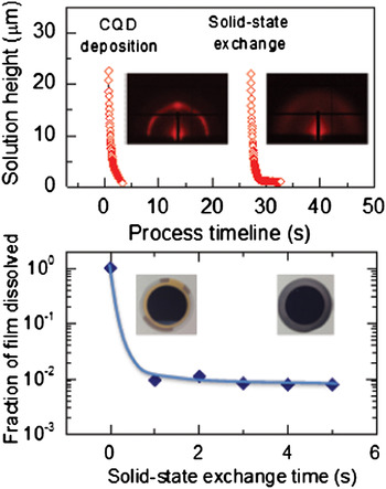
The solid-state ligand exchange that follows poses a more difficult kinetic challenge, since it requires (i) the solution and short ligands to permeate the 45–50 nm thick CQD film, (ii) the shorter ligands to react and replace the longer ligands to render the QDs insoluble, and (iii) the new solution to carry away the displaced long-chain ligands from the film. These complex phenomena are expected to determine how fast the ligands are exchanged and whether the QDs have sufficient time and the physicochemical ability to reorganize within the film. To estimate the speed of the solid-state exchange process, we have measured the solubility of the solid-state exchanged QD film in the original casting solvent for exchange times as little as ~1 s. Quartz crystal microbalance with dissipation (QCM-D) sensors were thus spin-coated with the QD film and solid-state exchange performed by dipping the sensor into the second solution from ~1 to 5 s duration and immediately blowing dry with N2. The pristine and exchanged films were then loaded into an open module of the QCM-D instrument (E4 model, QSense, Biolin Scientific) and octane was dropped on the surface of the sensor to monitor the mass loss as QDs dissolve and redisperse. As expected, the pristine film redispersed completely in octane. By contrast, all of the other treated films remained fully attached to the sensor [see Fig. 6(b)], suggesting that the exchange process renders the film insoluble to the process solvent on a subsecond time scale. The insets of Fig. 6(b) show the sensors coated with pristine and exchanged material after octane cleaning, illustrating the fact that the exchanged CQD film is not removed.
The speed of the solid-state ligand exchange process involving two-way mass transport, chemical reactions and volume change may explain why QDs have difficulty finding a thermodynamically lower energy state, i.e., a close-packed configuration, and explains the reduction in order in GISAXS images of CQD films following ligand exchange [Fig. 5(b) and right inset of Fig. 6(a)].
The layer-by-layer process also suffers the disadvantage of increased processing time and cost, undesirable for large-scale manufacture. The need for multiple coats in a roll-to-roll production-scale apparatus would increase solvent consumption. Thus, for reasons both of performance and scale-up, alternative fabrication procedures merit exploration.
Pathways to improvement
Two clear pathways exist to address the issues presented in the preceding sections. The first path, pursued by the majority of researchers in the field at the time of writing, involves working with the solid-state exchange framework, and making improvements at various stages of the process to address the listed issues and create a more efficient final device. Ongoing research will address ensuring complete solid-state exchange (full removal of initial ligand from the final film) while maintaining full surface passivation, to minimize detrimental trap states and improve electronic transport. Additional work will be carried out on densification, adjusting process parameters such as successive ligand length exchange steps, final ligand structure, and exchange conditions, in order to create denser, more homogeneously packed films. In all cases, observing process kinetics using in situ monitoring techniques will aid convergence toward the most promising processes and film configurations.
The second path involves a more fundamental rethinking of the way CQD solids are created. Here, a solution-phase exchange to the final desired ligand, followed by single-step film formation, would be attractive (Fig. 7). Once successfully devised, such an approach could offer a scalable means to fabricate well-passivated, and well-packed, CQD solids.
Schematic diagram of a simple solution exchange process. Rather than a layer-by-layer multiple exchange process, the solution exchange would switch long organic ligands for short capping molecules in solution, using a variety of techniques to remain colloidally stable. This exchanged solution is then cast onto a substrate in a single deposition step and dried to form a dense, ordered film of well-passivated QDs.
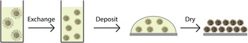
Steps toward this vision including the rapidly advancing field of QDs terminated, in the solution phase, using short capping ligands, examples of which include metal chalcogenide complexes[Reference Lee, Kovalenko, Huang, Chung and Talapin40, Reference Kovalenko, Scheele and Talapin53, Reference Liu, Lee and Talapin54] and simple chalcogenide ions[Reference Nag, Kovalenko, Lee, Liu, Spokoyny and Talapin55] by the Talapin group, thiocyanates[Reference Fafarman, Koh, Diroll, Kim, Ko, Oh, Ye, Doan-Nguyen, Crump, Reifsnyder, Murray and Kagan56] by Kagan and Murray, and short alkylthiols, with a trialkylsilylated chalcogenide-driven ligand exchange, by the Milliron group.[Reference Caldwell, Albers, Levy, Pick, Cohen, Helms and Milliron57] Excellent field-effect mobilities (1–10 cm2/V s range) have been reported, as have promising photoluminescence behavior. The absence of reports of high-performance bipolar devices, such as photodiodes, photodetectors, or electroluminescent devices, suggests that excellent transport and minimal excess recombination have yet to be combined within a single QD solid of this novel and highly promising class of materials.
On the path to high efficiency, low cost CQD photovoltaics, the next 3–5 years will see progress both on improved solid-state exchanges, and also on functional solution-exchanged materials. If the production of high-quality photovoltaic films from solution-exchanged QDs can be realized, this pathway will present an attractive avenue to production-scale generation of highly efficient photovoltaic devices.
Acknowledgments
This publication is based, in part, on work supported by Award KUS-11-009-21, made by King Abdullah University of Science and Technology (KAUST), by the Ontario Research Fund Research Excellence Program, and by the Natural Sciences and Engineering Research Council (NSERC) of Canada. G. H. C. acknowledges the financial support of the Vanier Canada Graduate Scholarship program.


