


Introduction
The emergence of reconfigurable intelligent surfaces (RISs) has sparked widespread interest due to their promise in advancing wireless millimeter wave and terahertz systems. As passive, tunable reflectors, RISs present an economically viable solution for overcoming hurdles in establishing robust communication links [Reference ElMossallamy, Zhang, Song, Seddik, Han and Li1, Reference Huang, Zappone, Alexandropoulos, Debbah and Yuen2]. From a hardware standpoint, a RIS can be conceptualized as a tunable reflectarray without a predefined feed. It comprises a periodic arrangement of individually tunable unit cells capable of adaptively manipulating electromagnetic waves. This manipulation enables arbitrary bending and rotation of wavefronts, facilitating either near-field focusing or far-field directing towards end users. An exemplary outdoor scenario is depicted in Fig. 1. Depending on the envisioned use case, there are several requirements a RIS should fulfill including low loss, wide bandwidth, wide angle beam-steering capabilities, fast response time, low power consumption and low cost.
Exemplary outdoor scenario for a RIS. The different colors in the RIS qualitatively indicate different reflected phase at the radiating elements. LoS: Line-of-sight.

In order to implement a RIS, a radiating element as well as a phase shifting mechanism are required. Conventionally, the phase shifting mechanism is realized with positive intrinsic negative (PIN) or varactor diodes. Promising realizations have been presented in [Reference Gros, Popov, Odit, Lenets and Lerosey3] and [Reference Pei, Yin, Tan, Cao, Li, Wang, Zhang and Björnson4]. However, at least one diode is required for each unit cell. As a result, power consumption and cost become serious challenges in large scale RIS, particularly since the cost for diodes tends to increase with frequency. These challenges are particularly pronounced considering the findings in [Reference Björnson, Özdogan and Larsson5], i.e.: at least hundreds of unit cells are required for a RIS to outperform active relay stations.
A promising alternative for the phase shifting mechanism are nematic LCs. By making use of the anisotropic nature of the LC molecules, tunable resonators and delay lines can be realized. There exist several challenges with LC, i.e. moderate insertion loss, temperature sensitivity and comparably slow response times compared to competing technologies such as semiconductors or MEMS [Reference Jiménez-Sáez, Asadi, Neuder, Delbari and Jamali6]. Nonetheless, LC also provides several benefits such as continuous tunability and applicability from the low GHz range up to several THz due to its decreasing loss with frequency. However, the most meaningful advantages come into play when LC is considered for large, flat surfaces: Its intrinsically low power consumption and low cost [Reference Jakoby, Gaebler and Weickhmann7].
There exist two architectures to realize flat tunable LC surfaces: The resonant architecture (RA) and the delay line architecture (DLA). The RA relies on the detuning of a resonant radiating element such that radiating and phase shifting layer are combined [Reference Perez-Palomino, Baine, Dickie, Bain, Encinar, Cahill, Barba and Toso8]. Its advantage is its simplicity, but it lacks the possibility to optimize towards wide bandwidth, low loss and fast response time simultaneously [Reference Neuder, Späth, Schüßler and Jiménez-Sáez9]. In the DLA, radiating layer and phase shifting layer are separated. By making use of a tunable delay line coupled to a radiating element, LC-RIS can be optimized towards bandwidth, loss and response time simultaneously. The functionality of this approach for LC-RIS has been demonstrated for a single linearly polarized RIS with 120 elements at  $60\,\mathrm{GHz}$ [Reference Neuder, Späth, Schüßler and Jiménez-Sáez9].
In light of the above, the DLA is considered in this contribution. In order to prove its feasibility in a dual linear polarized RIS, a unit cell is designed, fabricated and characterized around a center frequency of  $28\,\mathrm{GHz}$. This paper is structured as follows: First, the dual-polarized LC-RIS design is introduced and simulation results in a periodic environment are presented. Subsequently, the characterization results of a fabricated sample are shown. In addition, a comprehensive evaluation method for large-scale LC-RIS is introduced, enabling the analysis of beam-steering capabilities by simulating only a few unit cells. Finally, a conclusion is given. An earlier version of this paper was presented at EuMW 2024 and was published in its Proceedings [Reference Neuder, Liu, Dzieia, Wang and Jiménez-Sáez10].
Unit cell design
The layout of the dual-polarized LC-RIS based on the DLA is illustrated in Fig. 2a. Here, the unit cells are arranged in a rectangular grid. Each radiating element is coupled to two distinct tunable delay lines, one for each linear polarization. As shown in the side view, the incoming electromagnetic wave is coupled from the radiating element to the tunable delay line via aperture coupling. As a result, the wave travels through the delay line, is reflected at an open end and travels back to the radiating element, from which it is re-radiated. It is important to note that the element spacing should remain  $\leq 0.5\,\lambda_0$ to avoid grating lobes in the visible plane. Furthermore, complete
  $360^{\circ}$ phase tunability must be ensured in every delay line to fully exploit the continuous phase tunability of LC-based delay lines. Hence, the delay line topology must provide significant tunability in a limited space. In other words, a high compactness of the tunable delay line is required. Additionally, the delay line topology should also provide fast response time, low loss and wide bandwidth. For a fast response time in the order of milliseconds, a thin LC layer thickness
  $t_\mathrm{LC}$ of few µm is required [Reference Jakoby, Gaebler and Weickhmann7].
Unit cell characterization in simulations. (a) The perspective view of a 3  $\times$ 3 cut-out of a RIS and the side view of a tunable LC delay line coupled to a radiating element as well as the proposed dual-polarized LC-RIS unit cell. (b) The impedance matching of a unit cell, while (c)–(e) display its normalized radiation patterns.

As conventional topologies such as microstrip lines or coplanar waveguides lack compactness and lead to increasing conductor losses with decreasing substrate thickness [Reference Neuder, Wang, Schüßler, Jakoby and Jiménez-Sáez11], special delay line topologies must be employed. For that purpose, the defected ground structure inverted microstrip line (DGS-IMSL) is proposed as a tunable delay line for LC-RIS in [Reference Neuder, Wang, Schüßler, Jakoby and Jiménez-Sáez11] and [Reference Kim, Chae and Min12]. It is based on periodic defects in the ground plane of an inverted microstrip line (IMSL) resulting in a periodical loading of a series of capacitors. On top of reducing conductor losses (and hence, enabling thin  $\mathrm{t_{LC}}$), this topology increases compactness, making it a promising candidate for the use in DLA-based LC-RIS.
The materials used in this study are  $700\,\mu \mathrm{m}$ thick AF32 glass from Schott (
 ${\varepsilon_r = 5.1}$ and
  ${tan \delta = 0.009}$ at
  $24\,\mathrm{GHz}$ [13]), GT7-29001 (
 ${\varepsilon_{{r,\perp}}}=2.45$,
  ${\varepsilon_{{r, |}}}=3.53$,
  ${tan \, \delta_{\mathrm{\perp}}}=0.0116$ and
  ${tan \delta_{\mathrm{|}}}=0.0064$ at
  $19\,\mathrm{GHz}$ [Reference Fritzsch, Snow, Sargent, Klass, Kaur and Parri14]) from Merck as the tunable LC mixture and gold as a conductor. The LC thickness
  $t_\mathrm{LC}$ corresponds to
  $4.6\,\mu\mathrm{m}$. With these materials, the DGS-IMSL provides a figure of merit (FoM) of
  $75^{\circ}/\mathrm{dB}$ and a normalized length of
  $0.4\,\lambda_0$ at
  $27.5\,\mathrm{GHz}$ as demonstrated in [Reference Neuder, Wang, Schüßler, Jakoby and Jiménez-Sáez11]. In other words, for full
  $360^{\circ}$ tunability, the DGS-IMSL introduces a loss of
  $4.8\,\mathrm{dB}$ and requires a length of
  $0.4 \lambda_0$. Due to the additional space required for the radiating element, this compactness does still not suffice for an element spacing of
  $0.5\lambda_0$. Hence, as visible in the sketch of the unit cell in Fig.2a, the defected delay line is bent and the element spacing is increased to
  $0.536 \lambda_0$, which still enables grating lobe free steering between
  $-60^{\circ}$ and
  $+60^{\circ}$. Simulations show that the applied bending of the DGS-IMSL does not deteriorate its performance.
Electromagnetic simulations have been performed with CST Studio Suite 2024. Here, the unit cell is evaluated in a periodic environment, so that mutual coupling is taken into account. The impedance matching of the unit cell is exemplified in Fig. 2b for both extreme LC orientations achievable with the given topology ( ${\varepsilon_{r,LC} = 2.6}$ and
  ${\varepsilon_{r,LC} = 3.53}$ – for details, see [Reference Neuder, Wang, Schüßler, Jakoby and Jiménez-Sáez11]) and an intermediate state. It shows good matching behavior below
  $-10\mathrm{dB}$ for all LC states over the whole desired frequency range. Note that all presented results are valid for both linear polarizations as the setup is symmetric. The normalized radiation patterns are exemplified in Fig. 2c. The unit cell shows wide angle radiation in both planes and a cross polarization below
  $-12\mathrm{dB}$. Additionally, it is worth noting that the proposed dual-polarized unit cell exhibits scalability towards at least few hundreds of GHz.
Due to the limited space in the unit cells, the biasing scheme must also be addressed. In a fully assembled LC-RIS, two-dimensional beam steering can be realized using thin-film transistors. This approach, already established in liquid crystal displays (LCDs), enables element-wise biasing within a matrix and requires only N bias lines for the rows and M bias lines for the columns (see [Reference Neuder, Späth, Schüßler and Jiménez-Sáez9],[Reference Rose, Chen, Cranton and Fihn15]).
Unit cell measurement
In the previous section, simulation results for the proposed unit cell performance in a periodic environment are presented. In order to prove the performance in measurements, the unit cell is characterized as the center element in a 3  $\times$ 3 rectangular grid as presented in Fig. 3a. This modified setup provides an approximation of the periodic unit cell environment as the central element experiences mutual coupling from all its surrounding elements. The sample was fabricated using standard lithographic processes [Reference Karabey, Gaebler, Strunck and Jakoby16]. The exact dimensions of an unit cell are provided in the Supplementary Material Fig. 7. In order to enable coupling to a coaxial connector, the length of the DGS-IMSL delay line of the central unit cell is extended towards the boundaries of the 3x3 rectangular setup. For the sake of simplicity, the sample is characterized in the unbiased state only (
 ${\varepsilon_{r,LC} = 2.6}$). The antenna performance is measured with a Keysight VNA PNA-X N5247A and a standard
  $16\,\mathrm{dBi}$ gain horn antenna at a distance of approximately
  $60\,\mathrm{cm}$.
Unit cell characterization in measurements. (a) The fabricated sample from top and bottom view as well as the measurement setup. (b and c) The measured impedance matching at port 1 and port 2 and the radiation pattern of the sample, respectively.

The measured impedance matching of the unit cell is presented in Fig. 3b. Good matching is achieved in the desired frequency range between  $26.5$ and
  $29.5\,\mathrm{GHz}$ in good agreement with the simulations. The measured response times of a tunable delay line with GT7 and
  $t_\mathrm{LC}=4.6\,\mu\mathrm{m}$ correspond to
  $72$ and
  $15\,\mathrm{ms}$, for the switch-off and switch-on response times, respectively. On that basis, Delbari et al. [Reference Delbari, Neuder, Jiménez-Sáez, Asadi and Jamali17] shows that beam re-allocation in a large LC-RIS can be completed within less than 10 ms, depending on the considerations.
The extended defected delay line induces significant loss such that small parasitic influences (i.e. fabrication tolerances and the coaxial connector) have a deteriorating impact on the radiation pattern. In order to reduce parasitic influences, a time gating has been applied for evaluation of the radiation patterns to isolate the response of the antenna from undesired interfering signals.
Measured radiation patterns of the fabricated samples are presented in Fig. 3c. E- and H-plane show results comparable to simulations of the modified sample for all frequencies. Particularly the results for the E-plane reveal noticeable deterioration when compared to unit cell simulations in a periodic environment, mainly due to the extended delay line and the presence of the coaxial connector in that plane. Measured and simulated cross polarization is increased compared to unit cell simulations. However, measured values at  $28\,\mathrm{GHz}$ match with simulations of the modified setup and peak at around
  $-8.5\,\mathrm{dB}$ at this frequency.
Far-field beam-steering capabilities
In addition to the aforementioned unit cell features, the far-field beam-steering capabilities of the dual-polarized unit cell can be evaluated in terms of efficiency, loss contributions and bandwidth. However, a simulation of a large RIS with hundreds or even thousands of elements is a tedious process. This is particularly relevant for the DLA approach with thin  $ {t_{\mathrm{LC}}}$, as the phase shifter requires fine meshing, leading to high computational demands. Instead, we propose a simulation methodology to characterize the LC-RIS far-field beam-steering capabilities that significantly reduces computational complexity by requiring simulations of only a few unit cells instead of the entire structure.
First, the differential phase shift range inside the unit cell must be evaluated. The normalized differential phase shift and its dependence on the LC permittivity are presented in Fig. 4. The simulation setup consists of a square unit cell, with period  $D$, and two ports. The first port, Port 1, is applied directly to the phase shifter, and the second port is located on top of the simulation volume, at
  ${Z_{\mathrm{max}}}$, and excites/receives plane wave modes. To analyze the phase shift, a wave is excited at Port 1 and received at the plane wave port
  ${Z_{\mathrm{max}}}$. The simulated phase shifts are compared across the permittivity range of the applied LC-mixture. They are normalized to the lowest phase shift, corresponding to a permittivity of
  ${\varepsilon_{r,LC} = 2.6}$. Furthermore, the phase shifts are doubled because, in the desired LC-RIS operating in reflection mode, the wave passes through the unit cell twice. At
  $28\,\mathrm{GHz}$, the results show that less than
  ${\varepsilon_{r,LC} = 3.4}$ is required for full
  $360^{\circ}$ tunability. Thus, the unit cell design accounts for a potential 20% reduction in the total differential phase shift, which may result from the tolerances of the device fabrication. Hence, if fabrication tolerances are negligible, the phase shifter could be shortened to minimize losses.
Evaluation of unit cell phase shift with regard to the applied liquid crystal permittivity. On the left, the simulation setup is shown.  ${Z_{\mathrm{max}}}$ and Port 1 are the two simulation ports for excitation and reception of the electromagnetic modes. The black arrow attached to the
  ${Z_\mathrm{{max}}}$ port indicates its orientation.

With the knowledge of the permittivity-phase shift mapping, the beam steering capabilities can be analyzed. The focus lies on the evaluation of the co-polarization efficiencies and the determination of the sources of loss. The latter can be subdivided into material losses and mode conversion, e.g. cross-polarization or steering to undesired angles. To this end, there exist two approaches to evaluate beam steering capabilities in terms of efficiencies and losses with this numerical setup:
• Approach 1: Floquet mode-scattering analysis that takes into account an infinite metasurface made of supercells with
 $N$ unit cells and calculates the scattering into a discrete number of plane waves.
• Approach 2: Far-field efficiency analysis that considers a limited number of periodic supercells,
$M$, composed by
$N$ unit cells.


Using Approach 1, the periodicity of the metasurface will be defined by the number of unit cells  $N$ in the metasurface, leading to a supercell with
  $D_{\rm sc}=N D$ (see Fig. 5a).
  $D_{\rm sc}$ is the periodicity of the supercell composed by
  $N$ unit cells.
Efficiency calculation of the infinite size metasurface using Floquet-mode theory. (a) Representation of the simulation setup. (b) Exemplary excitation modes for the provided example corresponding to the specular mode and the first diffracted mode. (c) Co-polarization efficiency and cross-polarization losses for the 4 element unit cell steering towards the first diffracted mode. The acronyms neg. and pos. correspond to a steering towards the negative  ${\theta}$ and the positive
  ${\theta}$ direction, respectively, corresponding to
 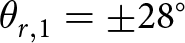 $\theta_{{r},1} = \pm28^{\circ}$ at
  $28\,\mathrm{GHz}$.

For an infinite periodic structure illuminated by a plane wave, the tangential wavenumber of the diffracted modes is given by the Floquet condition:
 \begin{equation}
k_{{x,n}} = k \sin\theta_{\rm i} + \frac{2\pi n}{D_{\rm sc}},
\end{equation}
\begin{equation}
k_{{x,n}} = k \sin\theta_{\rm i} + \frac{2\pi n}{D_{\rm sc}},
\end{equation} where  $k$ is the wavenumber at the operation frequency,
  $k_{{x,n}}$ is the tangential component of the wave vector of each Floquet mode,
  $\theta_{\rm i}$ is the incidence angle and
  $n$ denotes the order of the Floquet mode. Here,
  $n = 0$ corresponds to specular reflection. Following this definition, the normal component of the wave vector is given by
  $k_{{y,n}} = \sqrt{k^2 - k_{{x,n}}^2}$, and only the modes with
  $k \gt k_{{x,n}}$ propagate into free space. For a propagating mode, the reflection angle is determined by:
 \begin{equation}
\theta_{{r,n}} = \arctan\left(\frac{k_{{x,n}}}{k_{{y,n}}}\right).
\end{equation}
\begin{equation}
\theta_{{r,n}} = \arctan\left(\frac{k_{{x,n}}}{k_{{y,n}}}\right).
\end{equation} The incident power is distributed among these propagating modes depending on the configuration of the  $N$ unit cells that compose the supercell.
In our numerical model, the incoming wave is excited at  ${Z_{\mathrm{max}}}$ emulating a plane wave impinging from broadside the simulation domain, exemplified by the
  $\mathrm{TE_{00}}$ mode (see Fig. 5b) for representation of fields at the port for normal incidence. The energy reflected into specular direction,
  $\theta_{{r,0}}=\theta_{\rm i}$ will share the same profile. Cross-polarization in specular direction can also be characterized, such as through conversion into modes like
  $\mathrm{TM_{00}}$. In our case, the energy send towards the desired direction,
  $\theta_{{r,1}}$, is modeled by the coupling of energy into
  $\mathrm{TE_{10}}$ mode and the cross-polarization in this direction by the coupling of energy into
  $\mathrm{TM_{10}}$.
In the given example with four single element unit cells,  $\mathrm{D_{SC}=4 \, N}$, each element has an inter-element differential phase shift of
  $90^{\circ}$. Hence, the phases assigned to the elements are
  $0^{\circ}$,
  $90^{\circ}$,
  $180^{\circ}$,
  $270^{\circ}$, respectively. Notice that these phases are inserted in the simulation as LC substrates of varying permittivities. With regard to the inter-element spacing of
  $0.536 \lambda_0$, a
  $90^{\circ}$ inter-element phase shift accords to a steering towards approximately
  $\theta_{{r},1} = 28^{\circ}$ at
  $28\,\mathrm{GHz}$. Fig. 5c illustrates the broadband far-field co-polarization efficiency and cross-polarized scattering, with steering towards
  $\theta_{{r}, 1} = -28^{\circ}$ in the E-Plane and H-Plane as the phase gradient is oriented towards negative
  $x$.
$x$.
With the proposed setup, a range of reflected angles  $\theta_{r}$ have been evaluated. For that purpose, supercells with sizes of
  $D_\mathrm{SC} = 6\, N$,
  $D_\mathrm{SC} = 4\, N$ and
  $D_\mathrm{SC} = 3\, N$ were considered, enabling the analysis of inter-element phase shifts of
  $60^{\circ}$,
  $90^{\circ}$,
  $120^{\circ}$, respectively. Notice that the angle of reflection changes with number of elements according to Eq. 2.
However, this approach inherently limits the evaluation to a discrete set of reflection angles  $\theta_{r}$. To relax this limitation, we extend the analysis with an additional non-integer supercell size of
  $D_\mathrm{SC} = 2.5\, N$ corresponding to an inter-element phase shift of
  $144^{\circ}$. This approach can also be modeled as a supercell with
  $D_\mathrm{SC} = 5\, N$ analyzing the second-order Floquet mode (
 ${n=2}$) instead of the first mode (
 ${n=1}$).
The calculated reflected angles  $\theta_{r,n}$ are summarized in Table. 1. The applied permittivities to realize the desired phase shifts are provided in the Supplementary Material Table 1. Fig. 5c displays the co-polarization efficiencies
  $\eta_{\mathrm{Co}},\theta_{r,1}$ and the cross-polarization losses
  $L_{\mathrm{Cross}},\theta_{r,1}$ for
  $D_\mathrm{SC} = 4\, N$. The outcomes for
  $D_\mathrm{SC} = 6\, N$,
  $D_\mathrm{SC} = 5\, N$ and
  $D_\mathrm{SC} = 3\, N$ are provided in the Supplementary Materials Figs. 5 and 6.
Calculation of reflection angles  $\theta_{r,n}$ for different supercell sizes at
  $28\,\mathrm{GHz}$

a Calculated with Eq. 2.
b Equals  $D_\mathrm{{SC}} = 5 \, N$ for the second Floquet mode order
  $n = 2$.
The second approach to evaluate efficiency, Approach 2, goes one step further and considers the effect of a finite number of supercells in the RIS [Reference Díaz-Rubio and Tretyakov18, Reference Diaz-Rubio, Kosulnikov and Tretyakov19]. The goal of our study will be to consider that the RIS is made by an arrangement of  $M\times NM$ supercells in
  $xy$-plane. In Fig. 6a, the simulated electric far-field pattern of a single element unit cell is depicted at
  $28\,\mathrm{GHz}$. It is important to notice that in this simulation, due to the small periodicity of the unit cell, we do not operate on the metagrating regime where Floquet modes can propagate [Reference Ra’di, Sounas and Alù20] and it is not expected to have beam steering. By expanding the single element unit cell to the
  ${N=4}$ element supercell configuration with different permittivities, the far-field distribution becomes more focused and is steered towards the
  ${-\theta}$ direction, as it is shown in Fig. 6b. Finally, the four element supercell from (b) is scaled to a large LC-RIS with
  $M=9$ supercells (1296 elements). In other words, the unit cell element factor obtained in (b) is multiplied with the array factor in (c), which enables the evaluation of the far-field beam-steering capabilities of a large LC-RIS to be simulated by modeling only a small section instead of the entire structure.
Efficiency calculation for a finite size reconfigurable intelligent surface composed of the proposed dual-polarized liquid crystal-based unit cell. (a) The radiated far-field pattern of an unit cell with one element. (b) The radiated far-field pattern of a  $D_\mathrm{SC} = 4\, N$ supercell with an inter-element phase shift of
  $90^{\circ}$. (c) The radiated far-field pattern of 1296 (36
  $\times$ 36) elements, accomplished by multiplication of (b) with the array factor. The red-yellow-white (hot) color grading marks the intensity of the radiated electric field. The green color grading indicates the applied liquid crystal permittivity. Note: In the setup, the ground plane has been hidden to make the liquid crystal layer visible. (d and g) The broadband performance in terms of the steering efficiency in a heat map for the E-plane and the H-plane, respectively. (e and h) as well as (f and i) The results of the co-polarization efficiency
  ${\eta_\mathrm{Co}}$ and the cross-polarization loss
  $\mathrm{L_{Cross}}$ for the E-plane and the H-plane.

In Fig. 6d and g, the broadband co-polarization efficiencies  ${\eta_{Co}}$ of the presented setup are displayed in heat maps for E- and H-plane. These efficiencies are calculated as the ratio of the radiated electric far-field in the outgoing direction and the maximum reflected electric far-field of a perfectly conducting metal plate with the same size and distance to the plane wave port:
 \begin{equation}
{\eta_{\mathrm{Co}}} = \frac{\mathrm{Mag}_{\mathrm{Co,RIS}}(\theta_ {r},\phi_{r})}{\mathrm{Mag}_\mathrm{MP,max} \, \, {\mathrm{cos}}(\theta_{\mathrm{i}}) \, \, {\mathrm{cos}}({\theta_{r}})}.
\end{equation}
\begin{equation}
{\eta_{\mathrm{Co}}} = \frac{\mathrm{Mag}_{\mathrm{Co,RIS}}(\theta_ {r},\phi_{r})}{\mathrm{Mag}_\mathrm{MP,max} \, \, {\mathrm{cos}}(\theta_{\mathrm{i}}) \, \, {\mathrm{cos}}({\theta_{r}})}.
\end{equation}  $\mathrm{Mag}_{\mathrm{RIS}}(\theta_{r},\phi_{r})$ refers to the co-polarized electric far-field magnitude of the LC-RIS depending on the direction of the reflection of the wave described by
  $\theta_{r}$ and
  $\phi_{r}$.
  $\mathrm{Mag}_\mathrm{MP,max}$ refers to the maximum received electric far-field magnitude of the metal plate. The cosine terms account for the magnitude reduction regarding the angle of the incident and reflected waves,
  $\theta_{i}$ and
  $\theta_{r}$, respectively. Since all simulations are performed for an incident wave from broadside, Eq. 3 simplifies to:
 \begin{equation}
{\eta_\mathrm{Co}} = \frac{\mathrm{Mag}_{\mathrm{Co,RIS}}(\theta_{r},\phi_{r})}{\mathrm{Mag}_\mathrm{MP,max} \, \, {\mathrm{cos}}(\theta_{r})}.
\end{equation}
\begin{equation}
{\eta_\mathrm{Co}} = \frac{\mathrm{Mag}_{\mathrm{Co,RIS}}(\theta_{r},\phi_{r})}{\mathrm{Mag}_\mathrm{MP,max} \, \, {\mathrm{cos}}(\theta_{r})}.
\end{equation}The heatmaps show that the steering works equally well in E- and H-plane. Around its operating frequency, the LC-RIS starts to act like a metal plate, reflecting the wave back to broadside. The visible inclination of the steered beam arises from beamsquinting effects, which become more severe for larger steering angles.
Fig. 6e and h depicts the co-polarization efficiencies obtained from full-wave simulations for various supercell sizes  $\mathrm{D_{SC}}$ at
  $28\,\mathrm{GHz}$ in E- and H-plane. The full-wave results exhibit excellent agreement with the theoretically obtained values for the reflected angle
  $\theta_{r,n}$ listed in Table 1. Furthermore, it is shown that the LC-RIS supports wide angle beam-steering with only a fraction of the efficiency being lost. In Fig. 6f and i, the cross-polarization is given at
  $28\,\mathrm{GHz}$ in E- and H-plane. Cross-polarization losses can be computed using Eq. 4 by replacing
  $\mathrm{Mag}_{\mathrm{Co,RIS}}(\theta_{r},\phi_{r})$ with
  $\mathrm{Mag}_{\mathrm{Cross,RIS}}(\theta_{r},\phi_{r})$, the cross-polarized electric far-field magnitude. In addition to the presented plots, the heat maps for co-polarization efficiency and cross-polarization loss for all examined steering angles in both planes can be found in the Supplementary Material Figs. 1–4.
When comparing the two efficiency/loss evaluation approaches, each offers distinct advantages and disadvantages. Approach 2 provides detailed information on the exact steering angles for all evaluated frequency points considering a finite-size RIS. However, it requires numerous far-field computations (at each desired frequency point) and an additional post-processing step to compare results with a metal plate. Approach 1 eliminates the need for post-processing and directly delivers broadband results with precise values for all mode conversions considering an infinitely sized RIS. Its limitation, however, lies in the inability to generate a radiation diagram. In summary, both approaches yield identical results for efficiencies and losses. Depending on the required information, one approach may offer advantages over the other. However, since both can be derived from the same simulation file, a combination of the two is often recommended.
To conclude this paper, an analysis of the maximum efficiency of the dual-polarized LC-RIS unit cell is presented, along with a breakdown of the loss contributions. The results are obtained from the  $\mathrm{D_{SC}=4 \, N}$ supercell. The maximum co-polarized steering efficiency of the LC-RIS reaches 20.8% at
  $28.65\,\mathrm{GHz}$. The total losses of 79.2% are composed of material losses and power converted to undesired modes. The material losses account for 71.7%, divided in 41.1% dielectric losses (caused by the non-zero
  ${tan\delta}$ of the LC-mixture and glass substrate) and 30.6% conductor losses (caused by the finite conductivity of gold). Mode conversion accounts for a total of 7.5%. 1.9% and 1.3% are lost due to cross-polarization towards the steering angle
  ${\theta_{r,1}}$ and broadside, respectively. Cross-polarization could be further mitigated by applying careful consideration to the design and positioning of the coupling slot (e.g. see [Reference Rostan and Wiesbeck21]), ensuring that its geometry does not introduce unwanted field asymmetries. In addition to cross-polarization loss, 1.8% of the power are radiated towards the opposite side of the LC-RIS and 1.1% are reflected back to broadside. The remaining 1.4% are converted to various other undesired modes.
Thus, the unit cell loss is mainly determined by the lossy materials and could be considerably reduced with lower loss materials (for details, see [Reference Neuder, Späth, Schüßler and Jiménez-Sáez9]). In Table 2, the features of the proposed LC-RIS are summarized.
Summary of dual-polarized LC-RIS unit cell performance

a The minimum bandwidth required for efficiencies greater than 10% for all analyzed steering angles in both the E- and H-plane is evaluated, as shown in the supplementary material Fig. 5.
b Evaluated for steering towards 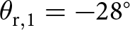 $\theta_{\mathrm{r},1} = -28^\circ$ (
 $D_\mathrm{SC} = 4 \, N$) at
  $28.65\,\mathrm{GHz}$.
c Dielectric (glass substrate and liquid crystal) and conductor (gold) losses.
Conclusion
This paper presents the design and comprehensive characterization of a unit cell for a dual-polarized liquid crystal reconfigurable intelligent surface operating at approximately  $28\,\mathrm{GHz}$. The unit cell is based on defected delay lines with a thin
  $4.6\,\mu\mathrm{m}$ liquid crystal substrate and aims for optimization of bandwidth, loss and response time simultaneously. Within this scope, measurements of the unit cell show good agreement with simulations in terms of impedance matching and single-element radiation characteristics. Additionally, a method is introduced to analyze the far-field beam-steering capabilities of a large-scale liquid crystal reconfigurable intelligent surface, requiring simulations of only a few unit cells rather than the entire surface. The results show a 10% efficiency bandwidth of 8.2% in a steering range from
  $-48^{\circ}$ to
  $+48^{\circ}$ in both, the E-Plane and the H-Plane. A maximum efficiency of 20.8% is accomplished.
Acknowledgements
This work was funded by the Deutsche Forschungsgemeinschaft (DFG, German Research Foundation) – Project-ID 287022738 – TRR 196 MARIE within project C09. In addition, thanks goes to Merck KGaA, Darmstadt, Germany for providing the liquid crystal mixture.
Competing interests
The authors declare no competing interests.

Robin Neuder received the B.S. and M.S. degree in electrical engineering and information technology from TU Darmstadt, Germany in 2019 and 2021, respectively. Since 2021, he has been a Research Assistant with the Institute of Microwave Engineering and Photonics at TU Darmstadt. His research interests include compact liquid-crystal based tuneable planar devices and their integration into Reconfigurable Intelligent Surfaces.

Ana Díaz-Rubio was born in Landete, Spain. She received the bachelor’s degree in telecommunication engineering and the M.Sc. and Ph.D. degrees from the Polytechnic University of Valencia, Valencia, Spain, in 2010, 2011, and 2015, respectively. She is currently Associate Professor in Universitat Politècnica de València (Spain). Her current research interest includes artificial thin surfaces for controlling wave propagation.

Yingzhe Liu is a Radio Frequency R&D Engineer with a background in both theoretical and applied RF technologies. He completed his undergraduate studies at the Universidad Politécnica de Madrid (UPM), graduating from the E.T.S.I.T. (Escuela Técnica Superior de Ingenieros de Telecomunicación) with a focus on RF systems. He further pursued his Master’s degree at the Technische Universität Darmstadt, Germany, specializing in the RF Technology. Currently, Yingzhe is part of the engineering team at TRUMPF, where he is engaged in the development of critical 13.56 MHz RF generator. These systems are essential components for semiconductor fabrication equipment, such as plasma etching and deposition tools, which are fundamental to the microchip manufacturing industry. His work effectively bridges academic research with high-impact industrial applications in the semiconductor sector.

Nora Dzieia received the B.Sc. degree in electrical engineering from TU Darmstadt and continued her education afterwards at Chalmers University of Technology in Gothenburg, Sweden. For her M.Sc. she is studying wireless, photonic and space engineering and focuses mainly on integrated photonics.

Dongwei Wang was born in Taiyuan, Shanxi, China. He received the B.Eng. degree from Zhejiang University, Hangzhou, Zhejiang, China, in 2014, and the M.Sc. degree from the Karlsruher Institut für Technologie, Karlsruhe, Germany, in 2018. He received Dr. Ing. degree in electrical engineering from Technische Universität Darmstadt, Darmstadt, Germany, in 2023. Since then, he joined Bosch Corporate Research Renningen, Germany. His research interests include electronically reconfigurable RF system and components, RF materials and automotive radar hardware.

Alejandro Jiménez-Sáez (S’15, M’22) received the master’s degrees (Hons.) in telecommunications engineering from the Polytechnic University of Valencia, Spain, and in electrical engineering from the Technical University of Darmstadt, Germany, in 2017. In 2021, he received the Dr.-Ing. degree (with distinction) in electrical engineering from the TU Darmstadt and the Freunde der TU Darmstadt prize for the best dissertation in electrical engineering. He obtained the Athene Young Investigator award at TU Darmstadt and leads the Smart RF Systems based on Artificial and Functional Materials independent research group. His current research interests include chipless RFID, electromagnetic bandgap structures, liquid crystal, and reconfigurable intelligent surfaces.


 Open access