


1. Introduction
The fluid dynamics of slotted/porous bluff bodies have attracted many fluid-dynamics researchers as it is relevant to wide engineering applications and rich fundamental physics. The slot in the bluff bodies alters/controls the periodic vortex-shedding phenomenon associated with the moving fluid. This results in a change in the base pressure and induces the fluctuating lift force on the cylinder. If the bluff body is free to oscillate, it shows structural vibrations and generates acoustic noise (Williamson Reference Williamson1996; Choi, Jeon & Kim Reference Choi, Jeon and Kim2008). The amplitude of these vibrations is highly amplified if the frequency of the cylinder oscillations is closer to the system's natural frequency, termed as ’lock-in’ in the literature (Zhang et al. Reference Zhang, Li, Ye and Jiang2015; Mittal et al. Reference Mittal2016). These high-amplitude vibrations are sometimes violent and result in the structure's catastrophic failure. Hence, finding new and efficient methods to eliminate/suppress such vibrations has been the focus of much research in the past, such as suction and blowing (Chen et al. Reference Chen, Xin, Xu, Li, Ou and Hu2013), momentum injection (Zhu et al. Reference Zhu, Tang, Zhao and Gao2019), attaching controlling rods (Zhu & Yao Reference Zhu and Yao2015), splitter plates (Hwang, Yang & Sun Reference Hwang, Yang and Sun2003), etc. Conversely, there have been studies to enhance and utilize such high-amplitude vibrations for different applications such as energy harvesting (Bernitsas et al. Reference Bernitsas, Raghavan, Ben-Simon and Garcia2008; Mehmood et al. Reference Mehmood, Abdelkefi, Hajj, Nayfeh, Akhtar and Nuhait2013; Grouthier et al. Reference Grouthier, Michelin, Bourguet, Modarres-Sadeghi and De Langre2014; Soti & De Reference Soti and De2020), thermal augmentations (Shi et al. Reference Shi, Hu, Schafer and Chen2014; Garg, Soti & Bhardwaj Reference Garg, Soti and Bhardwaj2019), vortex flow meters (Miller Reference Miller1983), etc. Introducing a slit in the bluff body is one of the most straightforward techniques to suppress/enhance these vibrations, depending on the position of the slit.
The first mention of the slit in controlling vortex shedding dates back to 1978 when Igarashi (Reference Igarashi1978) modified the circular cylinder with a normal slit and reported the strong and more stable vortex shedding behind the stationary slit cylinder at Reynolds number  ${Re} = 1.38 \times {10^4}\unicode{x2013}5.2 \times {10^4}$ for the range of slit inclination angles (
 $\beta$, defined as the angle between the incoming flow and the line passing through the slit centre). Igarashi identified two types of flow control with the slit: wake control by self-injection (for
  ${0^ \circ } \leq \beta \leq {40^ \circ }$) and the alternate boundary layer suction and blowing (for
  ${60^ \circ } \leq \beta \leq {90^ \circ }$). In his preceding work (Igarashi Reference Igarashi1982), he reported the resemblance of the wake behind the slit cylinder (for
  $\beta = {90^ \circ }$) with the wake of an oscillating airfoil. For a cylinder with a normal slit (
 $\beta = {90^ \circ }$), the pressure difference between the slit openings acts as the driving source for periodic blowing/suction with zero net mass flux (Ma & Kuo Reference Ma and Kuo2016). This exciting observation of Igarashi (Reference Igarashi1978, Reference Igarashi1982) and Ma & Kuo (Reference Ma and Kuo2016) has motivated the authors to select the inclination angle
  $\beta = {90^ \circ }$ for this study. At other slit inclination angles, as the slit inclination angle approaches zero (
 $\beta \to {0^ \circ }$, i.e. the case of the slit being parallel to the incoming flow), the self-issuing jet from the slit strengthens the secondary vortices attached to the cylinder and results in the suppressed vortex shedding behind the slit cylinder (Baek & Karniadakis Reference Baek and Karniadakis2009; Gao et al. Reference Gao, Chen, Li and Hu2017a,Reference Gao, Chen, Li and Hub; Mishra, Hanzla & De Reference Mishra, Hanzla and De2020; Mishra & De Reference Mishra and De2021; Verma, Mishra & De Reference Verma, Mishra and De2021).
All of the studies mentioned above assume the placement of the slit symmetrically at the centre of the cylinder. Recently, Zhu et al. (Reference Zhu, Zhuang, Li, Su, Bao and Liu2020) conducted an experimental study to understand the effect of asymmetrical placement of the normal slit by offsetting it from the cylinder's centre at  ${Re} = 2000\unicode{x2013}5400$. Their study suggests that placing the slit near the front stagnation point to a stationary cylinder leads to improved blowing and suction effects on the boundary layer, resulting in strong vortex shedding. While placing it near the rear stagnation point fails to generate the effective suction and blowing effect as flow separation occurs before the fluid can reach the slit. Thus, in the purview of the above literature, we observe that the placement of the slit in a circular cylinder strongly affects the flow dynamics by either suppressing or enhancing the vortex shedding behind the cylinder. This interesting behaviour associated with the offset slits has further motivated the authors to investigate this for the oscillating cylinder case.
The improved vortex shedding behind the slit cylinder (if mounted elastically) results in the high-amplitude oscillations of the cylinder, that are favourable for energy harvesting applications. Wind turbines are the conventional way to harness wind energy (Nedaei, Walsh & Assareh Reference Nedaei, Walsh and Assareh2020), but they are associated with several problems, viz. noise pollution, a threat to wildlife, portability, etc. Vortex-induced vibration (VIV) can be a potential substitute for wind turbines, where the energy can be harnessed via cylinder oscillations. With the increased understanding of the VIV phenomena, new techniques have been extensively developed to harness wind and water energy based on the VIV. Vortex-induced vibrations for aquatic clean energy (VIVACE, Bernitsas et al. Reference Bernitsas, Raghavan, Ben-Simon and Garcia2008) is an example of such a device, which maximizes the vortex shedding and exploits it for aquatic clean energy conversion. Recent research by Cottone, Vocca & Gammaitoni (Reference Cottone, Vocca and Gammaitoni2009) demonstrated the efficient use of nonlinear oscillators to convert energy from a broader vibration spectrum. Comprehensive experimental and numerical studies by Soti & De (Reference Soti and De2020), Soti et al. (Reference Soti, Thompson, Sheridan and Bhardwaj2017, Reference Soti, Zhao, Thompson, Sheridan and Bhardwaj2018) and Verma & De (Reference Verma and De2022a) adopt the principle of electromagnetic induction in a magnet-coil type energy harvester. They postulated the independence of the maximum average power from the length and radius of the coil and a strong dependence on the oscillation amplitude. The high oscillation amplitudes are observed during the lock-in, which occurs for a specific range of reduced velocities. Hence, increasing this range of reduced velocities is crucial for improving the applicability of VIV-based devices in energy harvesting.
Notably, most of the literature on flow control via a slit is available for the fixed/stationary cylinder. The literature suggests that a clear understanding of the boundary layer behaviour and flow physics is necessary for the efficient use of the slit for flow control. This behaviour of the boundary layer development shows the variation for the case of the oscillating cylinder with the stationary cases. Few studies (Baek & Karniadakis Reference Baek and Karniadakis2009; Verma et al. Reference Verma, Mishra and De2021; Verma & De Reference Verma and De2022b) considered the actual motion of the elastically mounted slit cylinder (with  $\beta = {0^ \circ }$) using numerical simulations to mitigate the VIV. No such study is available for the flow characteristics of a normal slit (
 $\beta = {90^ \circ }$). Thus, a considerable research gap exists in the fluid dynamic understanding of the three-dimensional flow physics behind the slit cylinder (
 $\beta = {90^ \circ }$) under 1-degree-of-freedom (1-DOF) VIV at low Re. To fill the research gap, the authors attempt to address the following relevant questions in the current study. (i) What effect does the placement of the normal slit have on the cylinder's oscillations amplitude and frequency response (especially on the amplitude branch behaviour and the lock-in)? (ii) In what ways do the slit width and reduced velocity affect the VIV characteristics of the slit cylinder? (iii) How does the placement of the slit affect the suction and blowing phenomena in the transversely oscillating slit cylinder? (iv) Does asymmetry in the slit position affect the energy extraction capacity of the slit cylinder? The authors try to address these questions by performing the three-dimensional numerical investigation of the flow field at
  $Re = 500$ over parametric variations, such as slit-offset position, slit width and their effects on the aerodynamic performance and the VIV characteristics.
2. Problem statement
The present paper investigates the VIV characteristics of an elastically mounted circular cylinder with a normal slit at a Reynolds number (Re, based on the cylinder diameter) of 500. The cylinder is mounted with the help of the spring-damper system such that it is restricted to oscillating in the transverse direction only (1-DOF VIV). The diameter of the cylinder is  $D$, the length of the cylinder is
  $9.6*D$, the slit width is
  $s$ and the slit inclination angle is
  ${\rm \pi} /2$ throughout the paper. The central angle (the angle between the vertical line passing through the cylinder's centre and the slit centreline) defines the slit-offset position (as in figure 1a). The mass ratio (
 ${m^*}$, defined as the ratio of the structural mass of the cylinder to the mass of the displaced fluid) of the cylinder is 10, and the damping ratio is taken as 0.02, representing the combined mass-damping ratio as 0.2. The study emphasizes the flow characteristics of offsetting the slit from the cylinder's centre to either side and its effect on the cylinder's oscillation response and energy harvesting capabilities. The equations are solved numerically over a three-dimensional computational domain shown in figure 1(b). The computational domain spans between
  $- 20 \leq x/D \leq 30$ in the streamwise direction,
  $- 20 \leq y/D \leq 20$ in the transverse direction and
  $0 \leq z/D \leq 9.6$ in the spanwise direction. The domain independence study has been performed to finalize the length of the domain downstream of the cylinder and the results are duly reported in Appendix A. The centre of the cylinder is at the origin. The incoming flow is assumed to be steady and uniform, while the advective boundary condition is used for the flow velocity at the outlet, which is a non-reflective boundary condition for velocity that solves the Euler equation
  ${{{\rm d}\phi } }/{{{\rm d}t}} + U({{{\rm d}\phi } }/{{{\rm d}n}} = 0$ at the exit boundary, where
  $n$ is the outward-pointing unit normal vector. The advection speed is the component of the velocity normal to the boundary, i.e.
  ${U_n} = {u_n}$. The free-slip boundary condition is applied to the spanwise and transverse boundaries, popularly used in past literature (Navrose & Mittal Reference Navrose and Mittal2013; Zhao et al. Reference Zhao, Cheng, An and Lu2014).
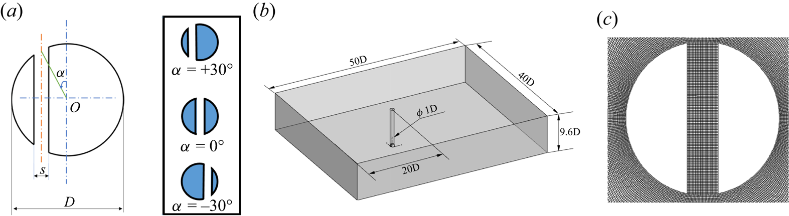
Figure 1. (a) The definition of the slit-offset angle, (b) schematic of the computational domain for the study, (c) zoomed view of the computational mesh near the slit cylinder.
3. Numerical details and validation
3.1. Governing equations
The incoming flow is assumed to be incompressible, viscous and laminar, which is solved over the mesh (shown in figure 1c) using the finite volume-based open-source CFD solver, OpenFOAM (Weller et al. Reference Weller, Tabor, Jasak and Fureby1998). The following equations govern the flow dynamics:
 $$\begin{gather} \boldsymbol{\nabla}\boldsymbol{\cdot}\boldsymbol{v} = 0, \end{gather}$$
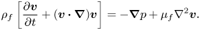 $$\begin{gather}{\rho _f}\left[\frac{\partial \boldsymbol{v}}{\partial t} + (\boldsymbol{v} \boldsymbol{\cdot}\boldsymbol{\nabla})\boldsymbol{v} \right] =- \boldsymbol{\nabla} p + {\mu _f}{\nabla ^2}\boldsymbol{v}. \end{gather}$$
Here  $\boldsymbol {v}$ is the velocity vector,
  ${\rho _f}$ is the fluid density,
  $p$ is the static pressure and
  ${\mu _f}$ is the dynamic viscosity of the fluid. The Reynolds number is defined based on the cylinder diameter (
 $D$) and the kinematic viscosity
  $(\nu = {\mu _f}/{\rho _f})$ as
  ${Re} = UD/\nu$. For the current study, the Re is fixed at 500 to assess the effect of offsetting the normal slit from the centre on the flow characteristics and the energy production. The pressure implicit method for pressure linked equations (PIMPLE) algorithm addresses the pressure–velocity coupling. All the spatial and temporal terms of the governing equations are discretized using the second-order discretization schemes.
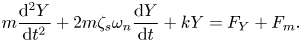
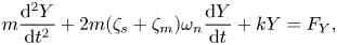
The motion of the elastically mounted rigid cylinder is governed by the linear mass-spring-damper equation as
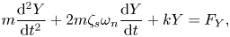 \begin{equation} m\frac{{{{\rm d}^2}Y} }{{{\rm d}{t^2}}} + 2m{\zeta _s}{\omega _n}\frac{{{\rm d}Y} }{{{\rm d}t}} + kY = {F_Y}, \end{equation}
where  $m$ is the mass of the oscillating system,
  ${\zeta _s}$ is the structural damping coefficient,
  ${\omega _n}$ is the natural frequency of the oscillating system (given as
  ${\omega _n} = \sqrt {k/m}$) and
  $k$ is the stiffness constant. Here
  ${F_Y}$ denotes the fluid forces obtained from the fluid solver as external forces (
 ${\rm pressure} + {\rm viscous}\ {\rm forces}$). Following previous literature, the motion of such vibrating systems can be described effectively using some of the non-dimensional parameters such as non-dimensional mass ratio,
  ${m^{*}} = m/({{\rm \pi} }/{4})\rho {D^2}L$, non-dimensional spring constant,
  ${k^*} = k/\rho {U_\infty }^2L$, non-dimensional damping coefficient,
  ${C^{*}} = c/\rho {U_\infty }DL$, non-dimensional reduced velocity,
  ${U_r} = {U_\infty }/{f_n}D$, non-dimensional natural frequency,
  ${f_{n}^{*}} = {f_n}D/{U_\infty }$, frequency ratio,
  $\,f^{*} = {f_y}/{f_n}$, non-dimensional time,
  $\tau = t{U_\infty }/D$, non-dimensional mean oscillation amplitude,
  ${A^{*}}$, and the phase between the lift force and the oscillation amplitude (
 $\phi = {\phi _{{F_y}}} - {\phi _y}$), calculated from the mean envelope of the Hilbert transform of the amplitude response.
To accurately simulate the system response, (3.1), (3.2) and (3.3) must be solved in a coupled manner. In each timestep, the fluid load is obtained from the solution of the flow equations. Then the motion of the boundaries is determined by the solution of the structural equation using the fourth-order Runge–Kutta scheme. Thus, this dependency of the fluid load on the velocity, acceleration and the cylinder's position makes the system nonlinear. We have used the weakly coupled form of the structural equation as the explicit function object in the OpenFOAM framework, in which the flow and structural equations are solved independently and sequentially, with coupling invoked by forces and boundary conditions. Detailed information on the weakly coupled form of the structural equation can be found in work by Jester & Kallinderis (Reference Jester and Kallinderis2004) and Carmo et al. (Reference Carmo, Sherwin, Bearman and Willden2011). The loosely coupled methods are extensively used in the literature (Piperno Reference Piperno1997; Mendes & Branco Reference Mendes and Branco1999; Schulz & Kallinderis Reference Schulz and Kallinderis2000; Carmo et al. Reference Carmo, Sherwin, Bearman and Willden2011; Verma & De Reference Verma and De2022a,Reference Verma and Deb). The timestep is selected based on the timestep independence study and is kept sufficiently small for better coupling convergence. To incorporate the mesh motion due to the movement of the cylinder, after each computational time step, the positions of the finite volume cells are computed by Laplace's equation,
 \begin{equation} \boldsymbol{\nabla}\boldsymbol{\cdot} ({\gamma _m}\boldsymbol{\nabla} z) = 0, \end{equation}
where  $z$ represents the mesh-cell centre displacement field and
  ${\gamma _m}$ is the mesh diffusion coefficient. Due to the fixed top and bottom boundaries, the mesh motion is distributed through the grid using the inverse mesh diffusion model based on the inverse distance from the cylinder body (Kassiotis Reference Kassiotis2008; Jasak Reference Jasak2009; Alletto Reference Alletto2022). It ensures that the farther away from the specified moving body, the less mesh morphing. The diffusivity field is based on the quadratic relation on the inverse of the cell centre distance (
 $l$) to the nearest boundary, i.e. (
 $1/{l^2}$).
3.2. Power extraction and energy harvesting
Electric power generation can be generated by attaching a magnet with the transversely oscillating cylinder along the axis of the conducting wire coil. The cylinder is connected to a magnet along the axis of an electrically conducting coil with a non-dimensional radius of  $a$, length of
  $L$ and
  $N$ turns (see figure 2). This arrangement constitutes a small electric generator unit based on electromagnetism. If the coil is connected to a resistive load, then an electric current is induced in the coil (Faraday's law). These eddy currents exert a drag force on the moving magnet and oppose its motion (Lenz's law) by applying an electromagnetic force,
 \begin{equation} {F_m}^{*} = {c_{m0}}{g^2}\frac{{{\rm d}{Y^{*}}} }{{{\rm d}t}}, \end{equation}
where  ${c_{m0}} = \mu _m^2/{(RD)^4}$ is a constant,
  $R$ is the resistive load,
  $D$ is the cylinder diameter,
  ${\mu _m}$ is the magnetic dipole moment of the magnet and
  $g$ is the function of the dimensions of the coil and its distance from the magnet. Based on the single magnetic dipole approximation (Donoso, Ladera & Martin Reference Donoso, Ladera and Martin2010),
  $g$ can be expressed as
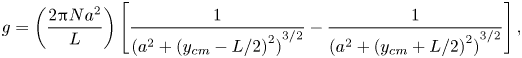 \begin{equation} g = \left( {\frac{{2{\rm \pi} N{a^2}} }{L}} \right)\left[ {\frac{1}{{{{({a^2} + {{({y_{cm}} - L/2)}^2})}^{3/2}}}} - \frac{1}{{{{({a^2} + {{({y_{cm}} + L/2)}^2})}^{3/2}}}}} \right], \end{equation}
where  $y_{cm}$ is the non-dimensional distance between the magnet and coil.
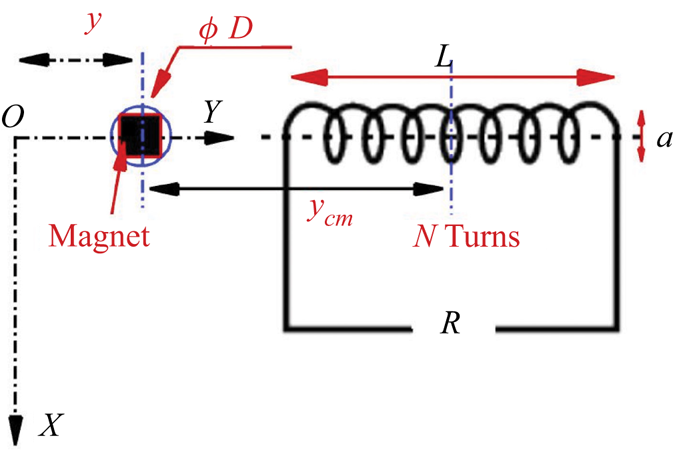
Figure 2. Cylinder-magnet arrangement layout for energy harvesting via electromagnetism.
This drag force can be numerically modelled as the electromagnetic damping term suggested by Soti et al. (Reference Soti, Thompson, Sheridan and Bhardwaj2017, Reference Soti, Zhao, Thompson, Sheridan and Bhardwaj2018). Thus, any power extraction method can be modelled as the addition of system damping. The electromagnetic force can be considered as a damping force with a damping ratio defined as  ${\zeta _m} = {\zeta _{m0}}{g^2}$, where
  ${\zeta _{m0}} = {c_{m0}}/{c_c}$; here
  ${c_c} = 4{\rm \pi} {m}{f_n}$ is the critical damping coefficient. Thus, the non-dimensional expression for the electromagnetic force becomes
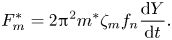 \begin{equation} {F^{*}_m} = 2{{\rm \pi} ^2}m^{*}{\zeta _m}{f_n}\frac{{{\rm d}Y} }{{{\rm d}t}}. \end{equation}
The function  $g$ determines how the damping ratio varies spatially, whereas the parameter
  ${\zeta _{m0}}$ regulates the overall amount of damping. Hence, the damping coefficient relies on the magnet-plate gap, magnet magnetic field intensity and conducting metal plate size, thickness and composition. The form of the equation of motion for such a magnet-coil-cylinder arrangement is
 \begin{equation} m\frac{{{{\rm d}^2}Y}}{{{\rm d}{t^2}}} + 2m{\zeta _s}{\omega _n}\frac{{{\rm d}Y}}{{{\rm d}t}} + kY = {F_Y} + {F_m}. \end{equation}
Using the above definitions, the form of (3.8) becomes
 $$\begin{gather} m\frac{{{{\rm d}^2}Y}}{{{\rm d}{t^2}}} + 2m({\zeta _s} + {\zeta _m}){\omega _n}\frac{{{\rm d}Y}}{{{\rm d}t}} + kY = {F_Y}, \end{gather}$$
 $$\begin{gather}m\frac{{{{\rm d}^2}Y}}{{{\rm d}{t^2}}} + 2m\zeta {\omega _n}\frac{{{\rm d}Y}}{{{\rm d}t}} + kY = {F_Y}. \end{gather}$$
 The total damping coefficient  $\zeta$ in (3.10) includes the damping coefficient due to losses in the transmission system (
 ${\zeta _s}$) and the added damping coefficient (
 ${\zeta _m}$) for electromagnetic energy harvesting. Damping coefficients for energy harvesting devices are typically modelled as constants (Barrero-Gil, Pindado & Avila Reference Barrero-Gil, Pindado and Avila2012). Soti et al. (Reference Soti, Thompson, Sheridan and Bhardwaj2017, Reference Soti, Zhao, Thompson, Sheridan and Bhardwaj2018) demonstrated that a model with a constant damping ratio predicts the same average power that will be extracted by a more realistic electromagnetic power extraction device in which the damping is not constant. Hence, we have used the constant value
  ${\zeta _m}$ in the current study. The product of the damping coefficient (C) and the square of the cylinder transverse velocity (
 ${\nu ^{*}_y}$) gives the estimate of the extracted power, which can be written in a non-dimensional form as
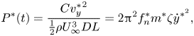 \begin{equation} P^{*}(t) = \frac{{C{v^{*}_y}^2}}{{\frac{1}{2}\rho U_\infty ^3DL}} = 2{{\rm \pi} ^2}f_n^*{m^*}\zeta {\dot y^{{*^2}}}, \end{equation}
where  $P^{*}(t)$ represents the instantaneous power extracted,
  $f_n^* = {f_n}D/{U_\infty }$ is the non-dimensional natural frequency,
  ${y^*} = y/D$ is the amplitude of the cylinder's displacement. Since the vibrations of the cylinder under VIV are treated to be sinusoidal and periodic (
 ${y^*} = A^*\sin (2{\rm \pi} f_{y}^{*}t/U_r$) with
  $T$ as the period of oscillation and
  ${f^*}( = {f_y}/{f_n})$ as the normalized oscillation frequency, the average extracted power over an oscillation cycle can be estimated as
 $$\begin{gather} {P_{avg}^{*}} = \frac{1}{T}\int\limits_0^T {P(t)\,{\rm d}t}, \end{gather}$$
 $$\begin{gather}{P^{*}_{avg}} = \frac{1}{T}\int\limits_0^T {2{{\rm \pi} ^2}f_n^*{m^*}\zeta {{({A^*}(2{\rm \pi} {f^*}/{U_r})\sin (2{\rm \pi} {f^*}t/{U_r}))}^2}\,{\rm d}t}, \end{gather}$$
 $$\begin{gather}{P^{*}_{avg}} = 2{{\rm \pi} ^2}f_n^*{m^*}\zeta \frac{1}{T}\int\limits_0^T {{{({A^*}(2{\rm \pi} {f^*}/{U_r}))}^2}{{\sin }^2}(2{\rm \pi} {f^*}t/{U_r})} \,{\rm d}t, \end{gather}$$
 $$\begin{gather}{P^{*}_{avg}} = 2{{\rm \pi} ^2}f_n^*{m^*}\zeta {({A^*}\omega )^2}\frac{1}{T}\int\limits_0^T {{{\sin }^2}(\omega t)} \,{\rm d}t, \end{gather}$$
where  $\omega = 2{\rm \pi} {f^*}/{U_r}$ is the frequency of oscillations.
 $$\begin{gather} {P^{*}_{avg}} = 2{{\rm \pi} ^2}f_n^*{m^*}\zeta {({A^*}\omega )^2}\frac{1}{T}\int\limits_0^T {\frac{{(\cos (2\omega t) + 1)} }{2}}\,{\rm d}t, \end{gather}$$
 $$\begin{gather}{P_{avg}} = \frac{{2{{\rm \pi} ^2}f_n^*{m^*}\zeta {{({A^*}\omega )}^2}}}{{2}}, \end{gather}$$
 $$\begin{gather}{P^{*}_{avg}} = {{\rm \pi} ^2}f_n^*{m^*}\zeta {({A^*}2{\rm \pi} {f^*}/{U_r})^2}. \end{gather}$$
Putting  ${f^*} = {f_y}/{f_n}$ and multiplying and dividing by
  ${U_r}$,
 $$\begin{gather} {P^{*}_{avg}} = 4{{\rm \pi} ^4}f_n^*{m^*}\zeta \frac{{{{({A^*}(\,{f_y}/{f_n}))}^2}} }{{U_r^2}}\frac{{{U_\infty }} }{{{f_n}D{U_r}}}, \end{gather}$$
 $$\begin{gather}{P^{*}_{avg}} = 4{{\rm \pi} ^4}f_n^*{m^*}\zeta \frac{{{{({A^*}(\,{f_y}/{f_n}))}^2}} }{{U_r^3}}\frac{{{U_\infty }} }{{{f_n}D}}. \end{gather}$$
Furthermore,  $\,f_n^* = {f_n}D/{U_\infty }$ will lead to
 $$\begin{gather} {P_{avg}} = 4{{\rm \pi} ^4}f_n^*{m^*}\zeta \frac{{{{({A^*}(\,{f_y}/{f_n}))}^2}} }{{U_r^3}}\frac{1}{{f_n^*}}, \end{gather}$$
 $$\begin{gather}{P_{avg}^{*}} = 4{{\rm \pi} ^4}m^{*}\xi {\frac{{((\,{f_y}/{f_n})A^*)}}{{U_r^3}}^2}, \end{gather}$$
where  $P^{*}_{avg}$ represents the non-dimensional average extracted power. This energy of oscillating cylinders is originally extracted from the kinetic energy of the flow, which for the projected area of the cylinder and the oscillation amplitude,
  $(D+2A)*L$, can be given as
 \begin{equation} {P_{fluid}} = \tfrac{1}{2}\rho U_\infty ^3(D + 2A)L = \tfrac{1}{2}\rho U_\infty ^3DL(1 + 2A^*). \end{equation}
Thus, the energy transfer ratio ( $\eta$, defined as the ratio of average extracted power to the available fluid power) can be written as
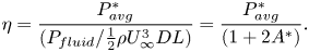 \begin{equation} \eta = \frac{{{P^{*}_{avg}}} }{{({P_{fluid}}/\frac{1}{2}\rho U_\infty ^3DL)}} = \frac{{{P^{*}_{avg}}} }{{(1 + 2A^*)}}. \end{equation}
3.3. Mesh independence, error analysis and numerical validation
To perform the grid independence study, we have simulated the transversely oscillating cylinder with a normal slit at a Reynolds number of 500. The slit width ( $s/D$) is taken as 0.2 and the slit-offset angle (
 $\alpha$) is taken as 0. The mass ratio of the cylinder is 10, with the damping ratio and the reduced velocity as 0 and 4.7, respectively. The
  $O$-grid blocking in ICEM-CFD (ANSYS 2016) is used in the near cylinder region to map the cylinder surfaces. The height of the first layer grid at the cylinder's surface is kept low
  ${y^ + } < 0.8$ with the cell expansion ratio of 1.02 in the small cuboid around the cylinder. The rest of the computational domain is filled with hexahedral cells with an expansion ratio of 1.2 to reduce the computational cost.
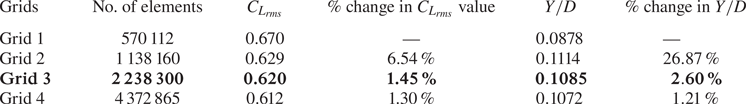
To ensure the grid independence of the results, the simulations are performed on four different grids, i.e. grid 1 (with 570 112 cells), grid 2 (with 1 138 160 cells), grid 3 (with 2 238 300 cells) and grid 4 (with 4 372 865 cells). Upon comparing the root-mean-square (r.m.s.) value of the lift coefficient ( ${C_{{L_{rms}}}}$) and the transverse oscillation amplitude (
 $Y/D$) in figure 3 and table 1, we can see that the differences between grid 3 and grid 4 drop to less than 2 %. Hence, grid 3 seems sufficient to carry out this study.
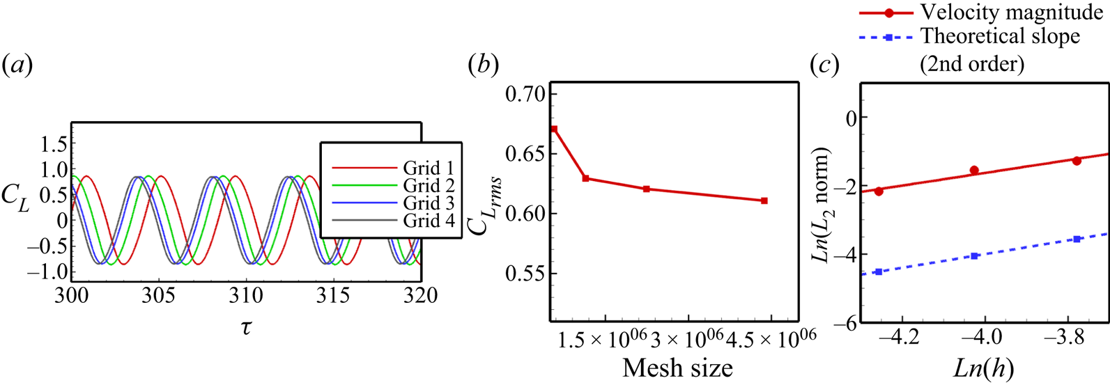
Figure 3. Grid independence study at  $Re = 500$ for an unconfined cylinder with a normal slit: (a) temporal variation of the lift coefficient (
 ${C_L}$), (b)
  ${C_{{L_{rms}}}}$ variation with the mesh size, (c)
  $L_2$ norm against the grid spacing
  $h$ compared with the theoretical slope for second order [
 ${m^*} = 10$,
  ${U_r} = 5$,
  $\zeta = 0.02$,
  $\alpha = {0^ \circ }$ and
  ${Re} = 500$].
Table 1. Grid independence study for the moving cylinder at  $Re = 500$ (values in bold show the selected grid).
Furthermore, to develop more confidence in the mesh, we have also performed the grid-convergence index (GCI) calculations proposed by Roache (Reference Roache1994, Reference Roache1997) and extensively used in the past literature. The GCI is based on the generalized Richardson extrapolation-derived grid refinement error estimator. The GCI can demonstrate how much the solution of the computed value might change with additional refining. A small GCI % number indicates that the computed value is approaching the asymptotic range. A detailed formulation of the GCI calculations can be found in Appendix B. We have considered the r.m.s. value of the lift coefficient ( ${C_{{L_{rms}}}}$) and the mean oscillation amplitude (
 ${A^*}$) for the GCI study. The best estimation safety factor is 1.25 (Ali, Doolan & Wheatley Reference Ali, Doolan and Wheatley2009). The results are duly tabulated in table 2. We observe the reduced GCI for the constitutive grid refinement for both parameters. These calculations confirm that grid 3 is nicely resolved. Also, figure 3(c) compares the slope of the
  $L_2$ norm with the theoretical slope of order 2. The order of accuracy (or the slope of
  $L_2$ norm) is found to be 1.927.
Table 2. Richardson error estimation and GCI for three sets of grids.

To confirm the coupling between the fluid and structural solver, we have validated the results with the previously published literature at a low mass ratio of 2 (for  $Re =150$) and 2.546 (for
  $Re = 1000$). The simulation data for the transverse oscillation amplitude and the oscillation frequency is duly compared with that of the results obtained by Ahn & Kallinderis (Reference Ahn and Kallinderis2006), Zhao et al. (Reference Zhao, Cheng, An and Lu2014), Bao et al. (Reference Bao, Huang, Zhou, Tu and Han2012) at
  $Re = 150$ (figure 4a,b), and Khalak & Williamson (Reference Khalak and Williamson1997), Lucor, Foo & Karniadakis (Reference Lucor, Foo and Karniadakis2005), Zhao et al. (Reference Zhao, Cheng, An and Lu2014) at
  $Re = 1000$ (figure 4c,d). The amplitude response nicely captures all the response branches, i.e. the initial branch (IB) and lower branch (LB) at
  $Re = 150$, and the IB, upper branch (UB) and LB at
  $Re = 1000$. The results are in good agreement with the available literature. The high-amplitude oscillations in the UB at
  $Re = 1000$ reported by Khalak & Williamson (Reference Khalak and Williamson1997) are not captured in our simulations as the Reynolds number was varied from 2000 to 12 000 during the experimental study to vary the reduced velocities, while it is kept constant during our simulations at
  $Re = 1000$.
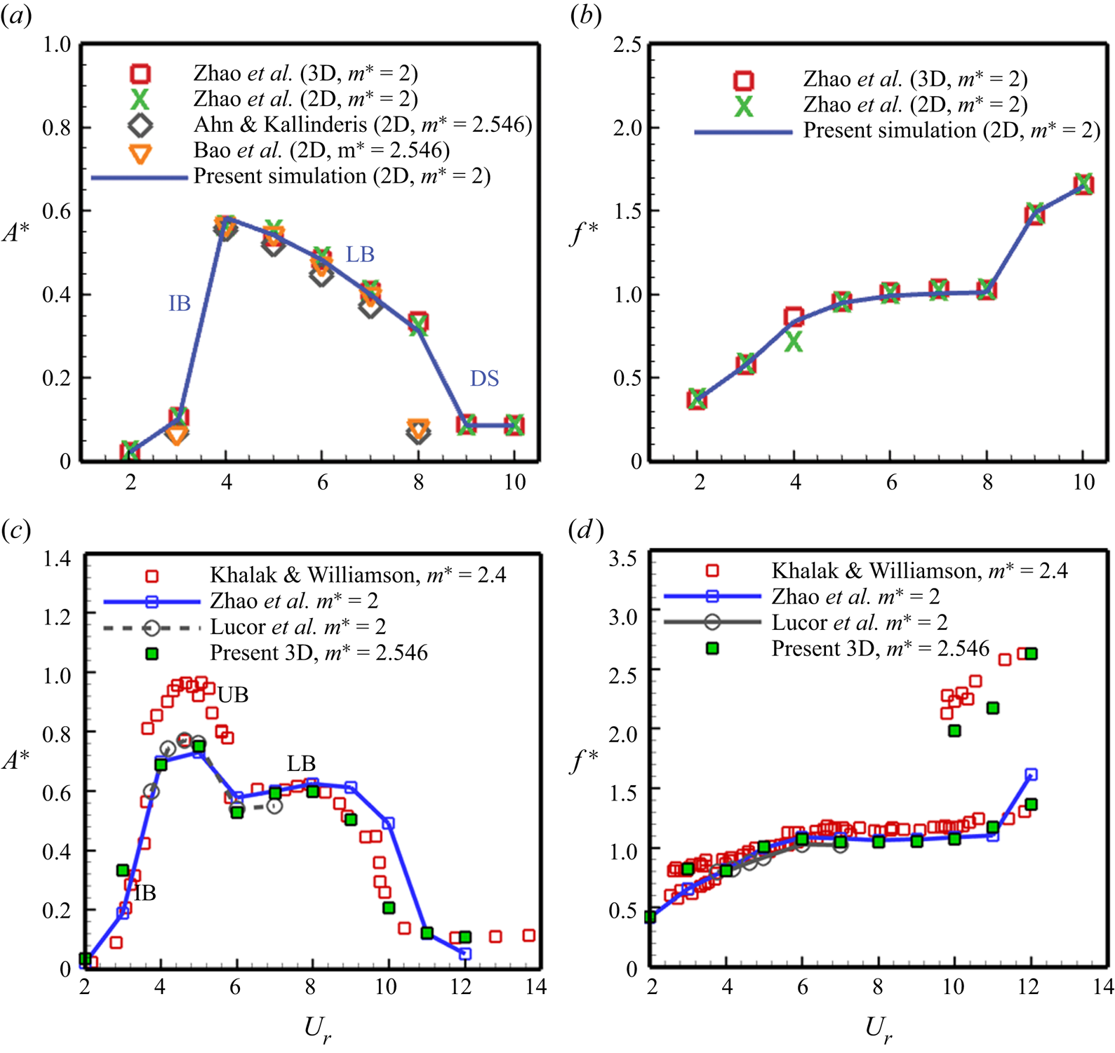
Figure 4. Numerical validation study for a transversely oscillating circular cylinder – amplitude and frequency response at (a,b)  $Re = 150$ and (c,d)
  $Re = 1000$ (
 ${m^*} = 2, \zeta = 0$).
4. Results and discussion
We have used the flow visualization technique to capture and understand the fluid dynamic aspects of placing a slit in the elastically mounted circular cylinder. The streamline patterns, vorticity contours and Reynolds stress distribution behind the cylinder characterize the fluid dynamic characteristics. At the same time, the aerodynamic loading coefficients (viz. r.m.s. of the lift coefficient), the associated transverse oscillation amplitude and frequency, and the phase difference between the force and the oscillation amplitude are looked at for the characterization of the VIV characteristics. We have performed fully resolved three-dimensional computational fluid dynamics simulations with the 1-DOF transverse motion at a Reynolds number of 500. The reduced velocity is fixed at 5, corresponding to the lock-in regime for the no-slit case. The structural damping coefficient ( $\zeta$) is set to 0.02 and the mass ratio (
 ${m^*}$) value is 10. Section 4.1 looks at the effect of the slit width on the VIV characteristics of the cylinder. The asymmetric placement of the slit is further explored in § 4.2 by looking at the flow visualization and the force decomposition. The observations are confirmed over a large set of reduced velocities in the preceding § 4.3. The last § 4.4 looks at the energy harvesting capabilities of the slit cylinder using the energy transfer ratio and compares it with the no-slit case.
4.1. Effect of slit width
To confirm the effectiveness of the slit-offset location, slit width plays an important role. We have simulated different slit widths for the case of a normal slit with the slit-offset angle  $\alpha = {0^ \circ }$ at the above mentioned VIV parameters. Figure 5 shows the effect of slit width on the lift and VIV characteristics of the slit cylinder, along with the visualization of the vortex shedding on the two-dimensional slice at the midspan. Here, the slit-width case
  $s/D = 0$ corresponds to the no-slit case. The vortex shedding for the lower slit widths (
 $s/D < 0.10$) is almost similar to the no-slit case, resulting in fewer effects on the flow and VIV characteristics. The flow in the slit is characterized by the appearance of the vortices at the top and bottom slit openings, alternatively, due to the establishment of the flow in the transverse direction through the slit. The transverse flow through the slit alters the pressure distribution over the cylinder surface due to the alternate suction and blowing of the boundary layer flow through the slit, which results in the reduced oscillation amplitude. Furthermore, as the slit width increases, the slit flow becomes stronger and induces the separation vortices developed very close to the cylinder surface, which alters the surface pressure so that the cylinder oscillations are much suppressed. Also, the flow through the slit increases, and the shear between the slit walls and the flow contributes to the lift increase. Since the flow and VIV characteristics remain almost the same after
  $s/D = 0.2$, we have used this slit-width value for the rest of the study. We have also performed simulations for two other slit-offset angles (i.e.
  $\alpha = {-30^ \circ }$ and
  $\alpha = {+30^ \circ }$) to assess the effect of slit width and observed that the lift and oscillation amplitude for those cases also do not vary much after the slit width of
  $s/D = 0.20$.
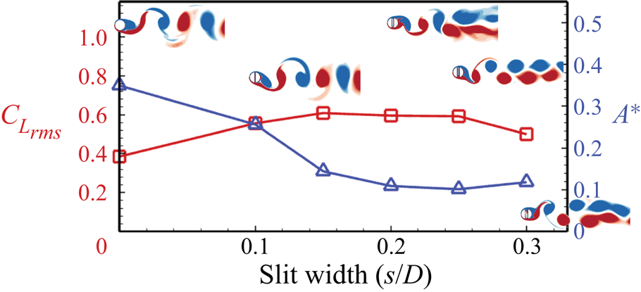
Figure 5. Effect of slit width on the lift force and corresponding transverse oscillations of the slit cylinder with the visualization of the vortex shedding via means of the instantaneous spanwise vorticity ( $- 5 \leq \omega _z \leq + 5$);
  ${m^*} = 10$,
  ${U_r} = 5$,
  $\zeta = 0.02$,
  $\alpha = {0^ \circ }$ and
  ${Re} = 500$.
4.2. Effect of slit-offset angle
4.2.1. Flow visualization with amplitude and frequency response
We have studied the fluid-flow dynamics of offsetting the slit from the centre toward the front and rear stagnation points, respectively. The slit-offset angle,  $\alpha$, controls the offsetting of the slit. The positive values
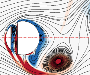
  $\alpha$ represent the offsetting toward the front stagnation point, while the negative values correspond toward the rear stagnation point. Figure 6 portrays the Reynolds shear stress distribution in the wake behind the cylinder, along with the time history of the transverse oscillation amplitude and the corresponding oscillation frequency. The Reynolds stress is obtained as the mean of the product of the fluctuating velocity components normalized with the square of the free-stream velocity (
 $\langle u'v'/U_\infty ^2\rangle$). The fluctuating component of the velocity is obtained by subtracting the instantaneous velocity from the mean velocity at that time instant (
 $u' = \tilde u - \langle u \rangle$). These statistics are collected once the flow characteristics show a quasi-steady periodic variation (
 $\sim$ after 200 flow-through times).
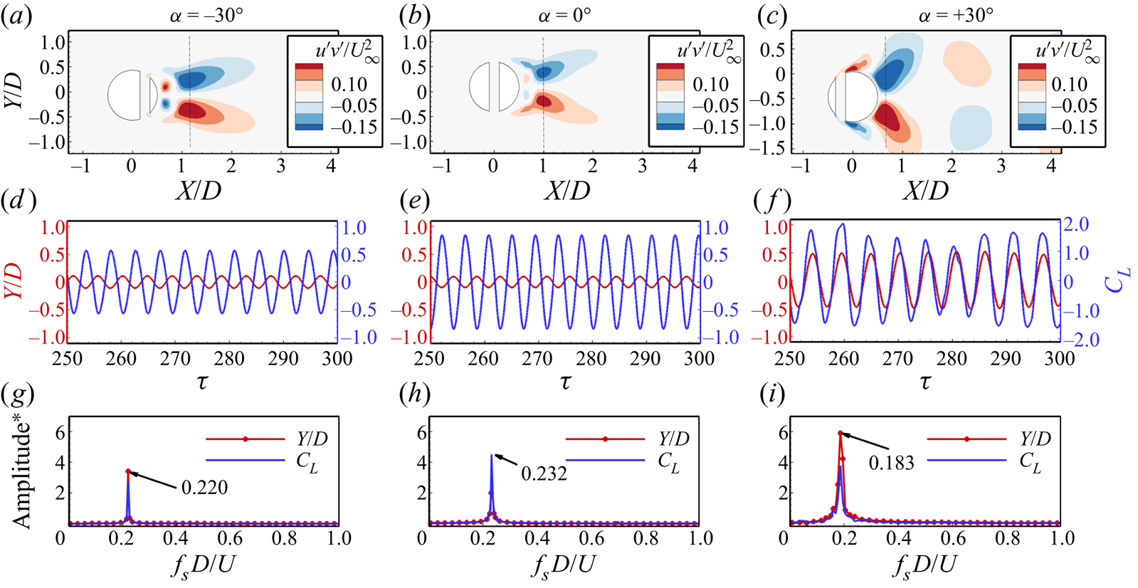
Figure 6. Effect of the slit offset on Reynolds stress distribution behind the transversely oscillating cylinder, the oscillation amplitude, the corresponding lift coefficient and the frequency spectrum ( ${m^*} = 10$,
  ${U_r} = 5$,
  $\zeta = 0.02$, and
  ${Re} = 500$).
We observe the anti-symmetric distribution of the Reynolds stress about the wake axis for all the cases, representing the alternate shedding of the vortices. The peak value of the Reynolds stress is observed in a tiny wake region behind the cylinder, indicating fewer disturbances in the associated wake. While for the offset slits ( $\alpha = - {30^ \circ }$ and
  $\alpha = + {30^ \circ }$), the peak values are distributed in a relatively larger area in the wake. One interesting thing to observe here is the shifting of the peak Reynolds stress values. For the
  $\alpha = + {30^ \circ }$ case, the peak stress values are closer to the cylinder surface, which indicates that the vortices are shed closer to the cylinder, resulting in the much destabilized wake behind the cylinder. The time history of the oscillation amplitude and the lift coefficient shows that the cylinder oscillates with the highest amplitude for offsetting the slit towards the front side of the cylinder. The oscillations are in phase with the lift force for
  $\alpha = + {30^ \circ }$, while for other cases (
 $\alpha = - {30^ \circ }$ and
  $\alpha = {0^ \circ }$), even though the lift coefficient is comparable, the oscillations are out of phase with the lift force resulting in a lower oscillation amplitude. Furthermore, the frequency spectrum reveals that offsetting the slit from the cylinder's centre reduces the oscillation frequency, with maximum reduction for the case of positive values of
  $\alpha$.
Further, to assess the three-dimensionality behind the oscillating cylinder with different slit-offset angles, we have plotted the isosurfaces of the second eigenvalue ( ${\lambda _2}$) of the tensor
  ${S^2} + {\varOmega ^2}$, where
  $S$ and
  $\varOmega$ are the symmetric and antisymmetric parts of the velocity gradient tensor
  $\boldsymbol {\nabla } u$. The eigenvalues are normalized using the free-stream velocity and the diameter of the cylinder
 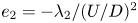 ${e_2} = - {\lambda _2}/{(U/D)^2}$, and the isosurfaces are coloured with the spanwise vorticity (
 $- 2 \leq \omega _z \leq + 2$). Figure 7 confirms that the wake behind the cylinder at this Reynolds number is three dimensional for all the cases. We find that the wake behind the cylinder with no slit is dominated by the streamwise rib-shaped structures that are not present in the case of
  $\alpha = + {30^ \circ }$.
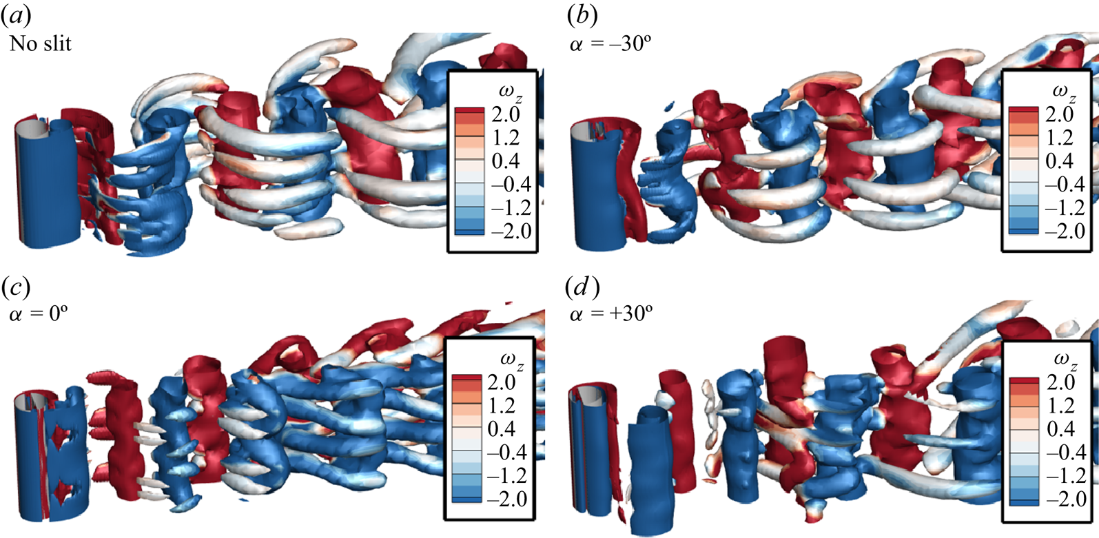
Figure 7. Three-dimensional structures behind the transversely oscillating circular slit cylinder for various slit-offset angles via means of the isosurfaces of eigenvalue  ${e_2} = 0.02$ (
 ${m^*} = 10$,
  ${U_r} = 5$,
  $\zeta = 0.02$ and
  ${Re} = 500$).
Figure 8(a) presents the variation of the mean transverse oscillation amplitude and the r.m.s. lift coefficient over the slit-offset spectrum, and visualization of the vortex shedding at different slit-offset angles via spanwise vorticity. Observation reveals that offsetting the slit towards the rear side of the cylinder results in no appreciable change in the oscillation amplitude, and the cylinder continues to oscillate out of phase with the lift force (as seen in the phase difference ( $\phi = {\phi _{{F_y}}} - {\phi _y}$) variation over the slit-offset angle in figure 8b). The cylinder sheds one pair of vortices, and the shedding is of the ‘2S’ type for the negative slit-offset angles. Shifting the slit towards the front side of the cylinder changes the vortex shedding, the vortices start to shed closer to the cylinder surface, and the phase difference between the oscillation amplitude and the lift force falls rapidly towards lower values. The positive values of
  $\alpha$ result in the strong suction of the boundary layer flow, which delays separation and the flow remains attached over a large surface area, resulting in the shedding of vortices closer to the cylinder's base. This behaviour is further explored in detail in the coming subsections.
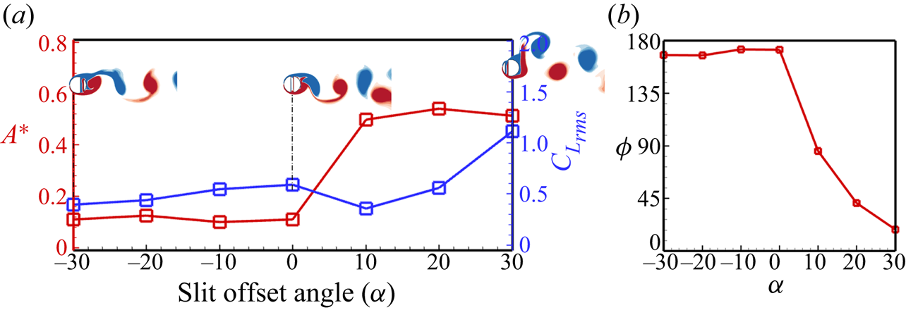
Figure 8. Effect of the slit-offset angle: (a) variation of transverse oscillation amplitude and the r.m.s. of the lift coefficient for different slit-offset angles (with visualization of the instantaneous vorticity ( $- 10 \leq \omega _z \leq + 10$)), (b) variation of the phase difference between the lift force and the oscillation amplitude (
 $\phi$);
  ${m^*} = 10$,
  ${U_r} = 5$,
  $\zeta = 0.02$ and
  ${Re} = 500$.
4.2.2. Unsteady vortex dynamics and shedding modes
Figure 9 portrays the unsteady vortex dynamics for the different slit offsets at five different time instants, i.e. 0,  $T/4$,
  $T/2$, 3
  $T/4$ and
  $T$, for one complete cycle of oscillation, where
  $T$ represents the period of oscillation. One thing that can be readily observed from figure 9 is the high-amplitude oscillations for the
  $\alpha = + {30^ \circ }$ case and a much wider wake behind the cylinder. For the
  $\alpha = - {30^ \circ }$ case, as the cylinder goes upwards from the centre, the primary vortex on the leeward side grows in size until the cylinder reaches the maximum positive oscillation amplitude at
  $t = T/4$. At
  $t = T/4$, the primary vortex leaves the cylinder surface. One small vortex appears on the bottom-leeward side of the cylinder, with another small counter-rotating vortex inside the slit at the bottom. As the cylinder moves downstream from the top position, the vortex on the slit washes away, and the vortices on the cylinder surface grow in size. The similar appearance of the pair of vortices (one on the top leeward side of the cylinder surface and one inside the slit at the top) is overserved at
  $t = 3~T/4$, facilitating the separation of the primary vortex from the cylinder surface. This occurs periodically and gives rise to the 2S type of shedding.
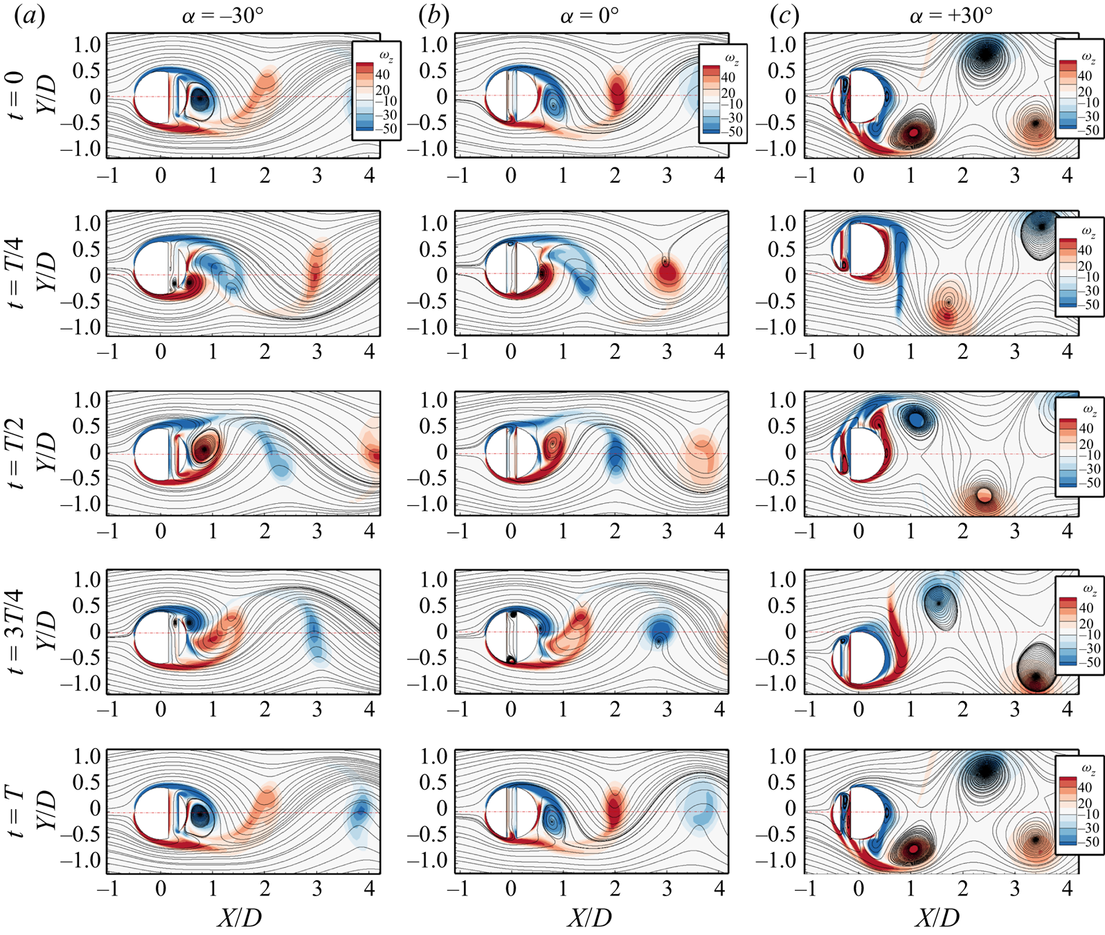
Figure 9. Temporal evolution of the instantaneous velocity streamlines for one complete oscillation cycle at different slit-offset angles: (a)  $\alpha = - {30^ \circ }$, (b)
  $\alpha = {0^ \circ }$ and (c)
  $\alpha = + {30^ \circ }$;
  ${m^*} = 10$,
  ${U_r} = 5$,
  $\zeta = 0.02, s/D = 0.20$ and
  ${Re} = 500$.
The vortex dynamics changes when the slit is placed at the centre of the cylinder. The primary vortex appears at the leeward side of the cylinder with a small vortex at the bottom slit opening at  $t = 0$. The vortex at the bottom slit opening switches its side inside the slit, and a new vortex appears at the top slit opening as the cylinder reaches the topmost position at
  $t=T/4$. This delays the separation of the shear layer on the cylinder surface resulting in the appearance of the two small vortices on the cylinder back surface with the two small reverse rotating vortices at the top and lower slit openings. As the cylinder moves downstream, the two vortices on the cylinder surface roll towards each other and merge before being convected into the wake at
  $t=T/2$. Meanwhile, the lower slit vortex decreases in size and returns when the cylinder reaches the lowest position at
  $t = 3~T/4$. Thus, a vortex is shed each half-cycle of the oscillation resembling the 2S vortex shedding.
For offset angle  $\alpha = + {30^ \circ }$, due to the very high oscillation amplitude, the vortex dynamics and the shedding differ from the other slit cases. The two significant differences identifiable by visual inspection of figure 9(c) are that the slit cylinder with the slit-offset angle
  $\alpha = + {30^ \circ }$ sheds stronger vortices behind the cylinder than the negative slit-offset angles. Also, the wake behind the cylinder for a positive slit-offset angle is wider than in the other cases owing to the higher oscillation amplitude. The close observation of the time snapshots of the
  $\alpha = + {30^ \circ }$ case shows that as the slit cylinder moves upwards from the centre position, the shear layer with the negative vorticity grows in size and separates from the rear surface of the cylinder. The slit vortices switch their location from the top slit opening to the lower slit opening at
  $t = T/4$. As the cylinder starts to move downwards, a small vortex (with negative vorticity) releases from the slit, and a larger vortex (with negative vorticity) from the rear surface of the cylinder sheds from the cylinder. Meanwhile, the shear layer with positive vorticity grows by a coalition of the two small vortices at
  $t = T/2$, and the slit vortex grows in size. As the cylinder reaches the lowest position at
  $t = 3~T/4$, the slit vortex switches its location from the bottom slit end to the top slit opening. The cylinder sheds one large vortex (with positive vorticity), and the slit releases a small vortex (with positive vorticity) into the wake, which dissipates away rapidly due to the influence of the larger vortex of the same vorticity. As the cylinder reaches the centre, the slit vortex on the top slit opening grows, and the same cycle repeats. Thus, the cylinder sheds two pairs of vortices in one complete cycle. Although the smaller vortices from the slit merge with the larger vortices momentarily, we observe the 2S type of shedding behind the cylinder in the vorticity contours (readers are advised to view the supplementary movies available at https://doi.org/10.1017/jfm.2023.479 for a better understanding of the unsteady behaviour). The alternate switching of the vortices is further investigated by temporal investigation of the pressure and velocity data at the slit openings in the following subsection.
4.2.3. Suction and blowing phenomena in slit cylinders
As the fluid passes over the cylinder surface, the velocity increases with the decrease in pressure, resulting in the thickening of the boundary layer over the cylinder surface. Based on the pressure difference between the top and bottom of the cylinder, the slit vent alternatively draws in the flow from the boundary layer and blows it out from the other end, termed as the suction and blowing phenomena in the literature. To access the effect of the suction and blowing phenomena for the different offset slits, we have looked into the probe data at the top and bottom openings of the slit for three different slit-offset angles in figure 10. The  $A$,
$A$,  $B$ and
  $C$ locations in figure 10 refer to the centre point of the slit openings for
  $\alpha = - {30^ \circ }$,
  ${0^ \circ }$ and
  $+ {30^ \circ }$ and the superscripts ‘
 $+$’ and ‘
 $-$’ refer to the top and bottom openings, respectively. The time history of the cylinder's oscillation amplitude is also plotted over the velocity probe data to better understand the slit flow dynamics. The pressure coefficient and the normalized transverse velocity of the slit flow are examined to understand the underlying flow physics in figures 10(a), 10(b) and 10(c). The pressure at the top and bottom openings of the slit changes periodically due to alternate suction and blowing in the slit. These pressure fluctuations are minimum for the
  $\alpha = {0^ \circ }$ case and maximum for the
  $\alpha = + {30^ \circ }$ case. The intense pressure fluctuations result in higher slit flow velocity magnitudes. Similar patterns are observed for the normal flow velocity component through which the flow flows inside/out of the slit. The positive values represent the suction of the flow from the boundary layer to the slit, while the negative values represent the blowing of the slit flow out of the slit into the boundary layer. The slit flow alters the pressure distribution over the cylinder and plays a role in the suppression/enhancement of the oscillation amplitude. One can observe that the flow velocity at the slit becomes zero momentarily as the flow direction changes due to the suction and blowing, following the study by Igarashi (Reference Igarashi1978, Reference Igarashi1982). For the case of
  $\alpha = - {30^ \circ }$ and
  $\alpha = {0^ \circ }$, the velocity at the slit's top and bottom openings is in phase with each other, and the pressure is out of phase. The time history of transverse oscillation amplitude is also plotted for these velocity plots to better understand the temporal signatures of the slit flow. As the cylinder moves upwards, the slit flow velocity is positive for the case of
  $\alpha = {0^ \circ }$, representing the blowing from the top end and the suction from the bottom end of the slit. When the cylinder starts to descend, the velocity sign changes and the top end starts to suck the flow from the boundary layer and blows it from the bottom end. For the asymmetric placement of the slit (
 $\alpha = - {30^ \circ }$), the suction and blowing behaviour remains the same, with relatively larger suction and blowing velocities.
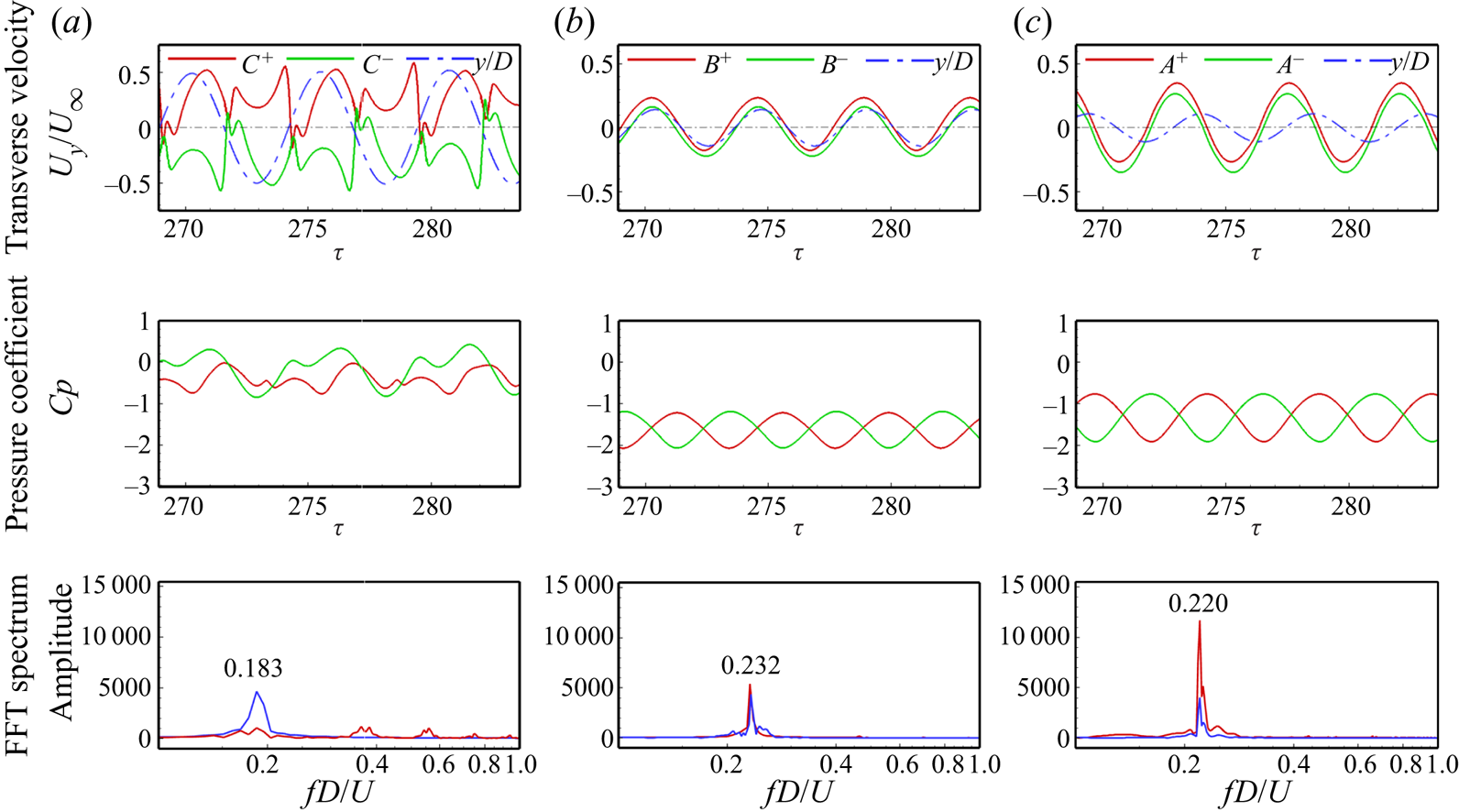
Figure 10. Development of suction and blowing phenomena inside the slit via the temporal evolution of pressure and velocity at the slit openings (top slit opening: red solid line, bottom slit opening: green solid line, the blue dashed dotted line shows the corresponding oscillation amplitude) for different slit-offset angles: (a)  $\alpha = + {30^ \circ }$, (b)
  $\alpha = {0^ \circ }$ and (c)
  $\alpha = - {30^ \circ }$;
  ${m^*} = 10$,
  ${U_r} = 5$,
  $\zeta = 0.02, s/D = 0.20$ and
  ${Re} = 500$.
Furthermore, for the asymmetric placement of the slit at  $\alpha = + {30^ \circ }$, the behaviour is entirely different from the other two cases. The velocity signals at the top and bottom slit openings show the out-of-phase behaviour. Due to the placement of the slit near the front stagnation point, the pressure coefficient values are higher for this case. The time history of the oscillation amplitude shows that the blowing from the slit's top end occurs when the cylinder goes upwards from the centre. As the cylinder alters its direction, the blowing from the slit's bottom end dominates until it reaches the centre again. At the centre position, the slit is filled with two counter-rotating vortices. The frequency spectrum of the probe velocity signal reveals that for the case of
  $\alpha = {0^ \circ }$ and
  $\alpha = - {30^ \circ }$, the frequency of the alternate suction and blowing matches well with the cylinder's oscillation frequency. While placing the slit at
  $\alpha = + {30^ \circ }$ gives rise to higher harmonics in the probe velocity signal representing the shedding of small-scale structures from the slit.
4.2.4. Global instability representation by r.m.s. of fluctuation velocities
We have also further analysed the global instability representation of the flow oscillations via the maximum values of r.m.s. fluctuation intensities over the entire domain, as suggested by Delaunay & Kaiktsis (Reference Delaunay and Kaiktsis2001). The maximum values of r.m.s. fluctuation intensities ( $u_{rms}^{\prime }$ and
  $v_{rms}^{\prime }$) are calculated by collecting the values along the lines of constant
  $x$ for different axial locations on the two-dimensional slice at the midspan of the cylinder. Figure 11 reports the maximum values of the r.m.s. of the fluctuation intensities for different slit-offset angles and compares them with the no-slit case. Also, the trend is compared with the results of Delaunay & Kaiktsis (Reference Delaunay and Kaiktsis2001) for the case of the stationary cylinder at
  $Re = 90$. Figure 11 provides more precise insights into the effects of suction and blowing in the near and far wake. Suction increases the velocity fluctuations in the entire wake while blowing dampens the fluctuations to zero in the near wake and an almost constant non-zero level farther downstream. Also, blowing displaces the fluctuation maxima downstream. Thus, we observe that the maxima in the near wake region are closest to the cylinder (figure 11), representing the vortex formation and shedding at a decreased streamwise location behind the cylinder. Also, the fluctuation levels in the far wake region are higher than in the other cases, denoting the strong suction and blowing phenomena at
  $\alpha = + {30^ \circ }$. For the other cases, the lower intensities in the far wake region support the wake stabilization behind the slit cylinder. Thus, the slit at the centre of the cylinder stabilized the flow behind the cylinder, reducing the Reynolds stress and causing the reduced oscillation amplitude. Peak values for the case of
  $\alpha = - {30^ \circ }$ shift away from the cylinder, indicating that the cylinder experiences a reduced Reynolds number (Nishioka & Sato Reference Nishioka and Sato1978) and much further reduced oscillations for that case.
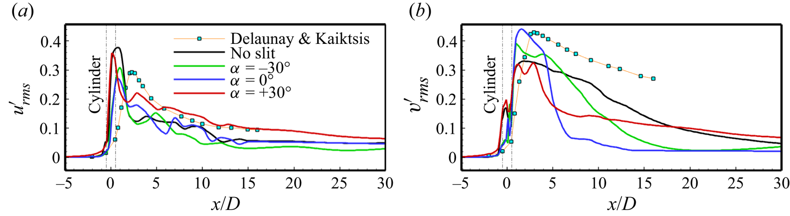
Figure 11. Maximum r.m.s. velocity fluctuations along the line of constant  $x/D$ for different slit-offset angles: (a) axial velocity fluctuations (
 $u_{rms}^{\prime }$) and (b) transverse velocity fluctuations (
 $v_{rms}^{\prime }$). (The trend is duly compared with the results obtained by Delaunay & Kaiktsis (Reference Delaunay and Kaiktsis2001) for the stationary cylinder at
  $Re = 90$).
4.2.5. Force decomposition in offset slit cylinders
A detailed analysis of fluid force is reported in this section to further investigate the associated flow dynamics. Three configurations associated with different slit offsets ( $\alpha = - {30^ \circ }$,
  $\alpha = {0^ \circ }$ and
  $\alpha = + {30^ \circ }$) highlight some of the properties of the fluid force. Since the cross-flow component of fluid force drives the cylinder's oscillations, the focus is placed on it. Figure 12 shows the total cross-flow force fluctuations and the fluctuations of pressure and viscous parts of this force for three different slit-offset angles
  $\alpha = - {30^ \circ }$,
  ${0^ \circ }$ and
  $+ {30^ \circ }$ on the left axis. The right axis in figure 12 shows the fluctuation of the cylinder displacement.
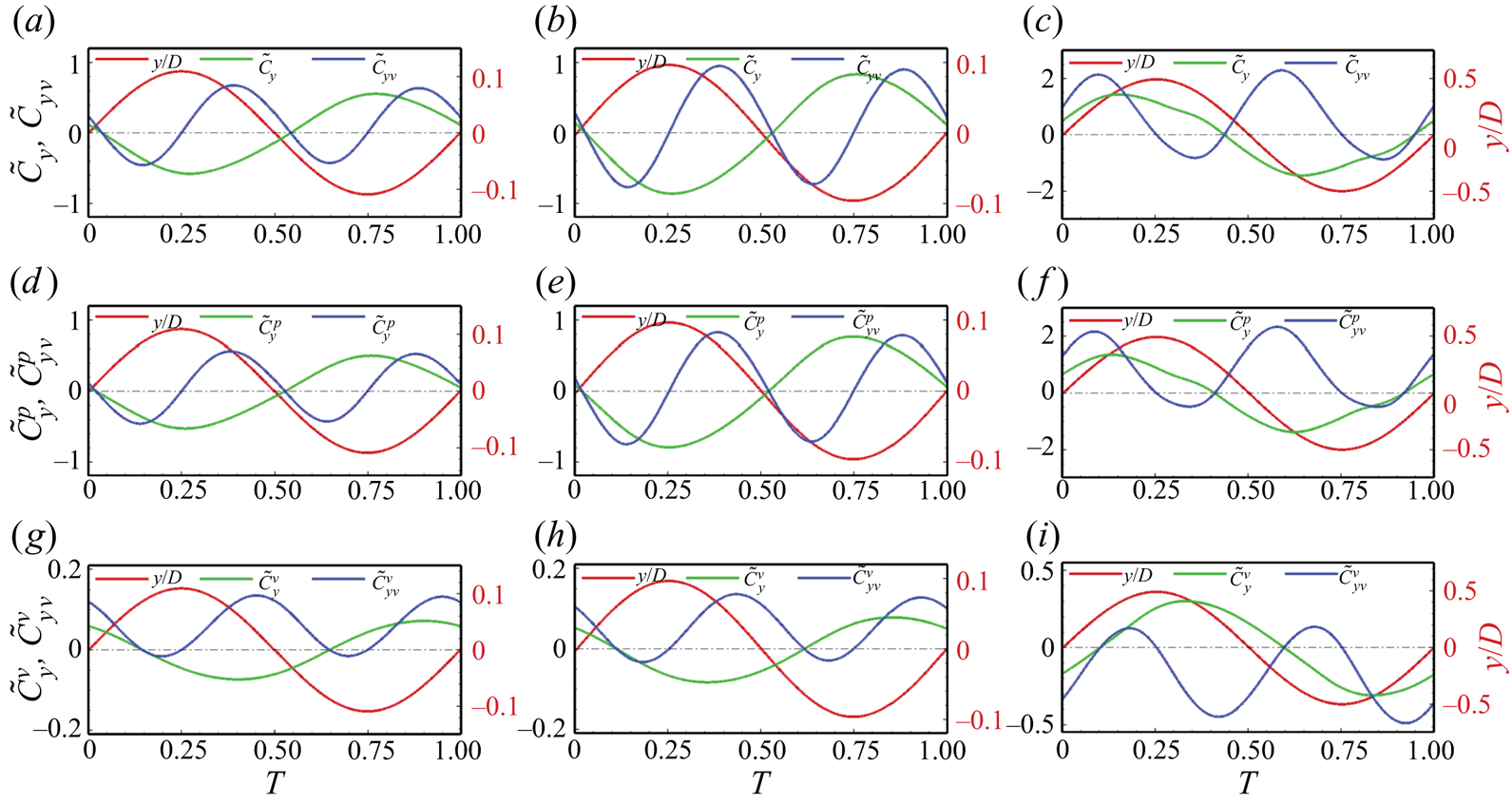
Figure 12. Temporal evolution of the cross-flow force fluctuation (green line, left axis) and cylinder displacement fluctuation (red line, right axis) for slit-offset angles (a)  $\alpha = - {30^ \circ }$, (b)
  $\alpha = {0^ \circ }$ and (c)
  $\alpha = + {30^ \circ }$ for (a–c) the total cross-flow force fluctuation coefficient,
  ${\tilde {C}_y}$, (d–f) the pressure component,
  $\tilde {C}_y^P$ and (g–i) the viscous component
  $\tilde {C}_y^V$. The instantaneous power (
 ${\tilde {C}_{yv}}$,
  $\tilde C_{yv}^P$,
  $\tilde {C}_{yv}^V$) due to the corresponding force component is also shown (blue line, left axis).
In the three cases it can be observed that the cross-flow force and its decomposed parts show substantial variations for different slit-offset angles. However, there are some similar features. In all cases, the oscillation is almost sinusoidal, which is not the case for the cross-flow force. The cross-flow force for the  $\alpha = + {30^ \circ }$ case is not fully sinusoidal and shows asymmetry. The asymmetry is mainly due to the pressure part, whereas the viscous part remains relatively symmetrical. A coupled observation of the time series and the flow snapshots allows us to relate some events in the evolution of the pressure force. For instance, time snapshots of the flow streamlines reveal that the pressure force asymmetry is related to the appearance of the small vortices for the
  $\alpha = + {30^ \circ }$ case at that time. For the
  $\alpha = - 30^{\circ }$ and
  ${0^ \circ }$ cases, the formation of the positive-vorticity vortex at
  $t = T/4$ seems to pull the cylinder downwards and is connected to the negative value of the force. The peak of the cross-flow force for such offset angles (
 $\alpha \leq 0^ \circ$) matches with the formation of the negative-vorticity vortex at
  $t = 3~T/4$ (see figure 9) and results in the upwards pull on the cylinder. For the positive values of the slit-offset angle (
 $\alpha > 0^ \circ$), the peak of the cross-flow force is near the peak displacement. The peak of the cross-flow force is related to the formation of two small negative-vorticity vortices, which further pull the cylinder upwards. Conversely, the lowest cross-flow appears before the lowest displacement, indicating the appearance of the positive-vorticity vortices, which seem to pull the cylinder further downstream.
Figure 12 also depicts the temporal variation of the fluid force coefficients ( ${\tilde {C}_{yv}}$,
  $\tilde {C}_{yv}^P$ and
  $\tilde {C}_{yv}^V$) in phase with the cylinder velocity for one complete oscillation cycle. These force coefficients can quantify the instantaneous energy transfer between the flow and the structure (Bourguet & Lo Jacono Reference Bourguet and Lo Jacono2014). The corresponding coefficients are defined as
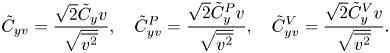 \begin{equation} {\tilde{C}_{yv}} = \frac{{\sqrt 2 {{\tilde{C}}_y}v}}{{\sqrt {\overline {{v^2}} } }},\quad\tilde{C}_{yv}^P = \frac{{\sqrt 2 \tilde{C}_y^Pv} }{{\sqrt {\overline {{v^2}} } }},\quad \tilde{C}_{yv}^V = \frac{{\sqrt 2 \tilde{C}_y^Vv} }{{\sqrt {\overline {{v^2}} } }}. \end{equation}
 Negative values of these coefficients represent the damping of the oscillations by the flow, while positive values indicate increased structural oscillations by the flow. The time-averaged net energy transfer for slit angles  $\alpha = - {30^ \circ }$ and
  ${0^ \circ }$ is close to zero, while it is positive for the
  $\alpha = + {30^ \circ }$ case. From figure 12 we observe that, for the case of the offset angles
  ${0^ \circ }$, the viscous part of the force principally supports the oscillations (
 $\tilde {C}_{yv}^V > 0$), except in the short time intervals (near
  $t = T/4$ and
  $3~T/4$), where
  $\tilde {C}_{yv}^V$ may become slightly negative. Conversely, for the offset angle
  $\alpha = + {30^ \circ }$, the viscous part of the force is negative over most of the oscillation cycle, indicating the damping of the cylinder oscillations. For this slit angle, the pressure part of the force (
 $\tilde {C}_{yv}^P > 0$) drives the excitation of the cylinder by the flow.
4.3. Effect of velocity ratio
The discussion in the preceding sections on the different flow characteristics associated with the offset slit cylinders was based on the response obtained during the lock-in at the fixed reduced velocity of 5. The response may differ in the other response branches. Hence, based on the above discussions, we have identified the two different slit-offset angle cases, viz.  $\alpha = - {30^ \circ }$ (corresponding to the leftmost extreme of the slit placement) and
  $\alpha = + {30^ \circ }$ (corresponding to the rightmost extreme of the slit placement). These cases are further compared with the case of no slit.
4.3.1. Oscillation amplitude and frequency response
Figure 13 shows the variation of the r.m.s. value of the lift coefficient ( ${C_{{L_{rms}}}}$), the corresponding oscillation amplitude and the frequency response over the wide range of reduced velocities for the two different slit-offset angles. The amplitude response is further compared with that of the no-slit case. The amplitude response for the no-slit case exhibits the two-branch response, i.e. the IB (
 $3.5 \leq {U_r} \leq 4.5$) and the LB (
 $3.5 \leq {U_r} \leq 4.5$). The cylinder exhibits a multifrequency oscillation response during the IB and attains the dominant harmonics close to the natural frequency with the peak oscillation amplitude (
 $A_{max }^* = 0.4$) at the start of the LB (
 ${U_r} = 4.5$). The oscillation response is periodic with one dominant harmonics during the LB (
 $4.5 \leq {U_r} \leq 6$) and decreases continuously with the increase in the reduced velocity. At the end of the LB, the cylinder oscillates with a low constant oscillation amplitude and shows the desynchronized amplitude response with the dominance of multiple frequencies. For slit cylinders at such a configuration (
 ${m^*}\zeta = 0.2$), the amplitude response shows a response similar to the no-slit case, i.e. two-branch response with the IB, followed by the LB. Although, the peak amplitude value and range of the high-amplitude oscillations differ for each slit-offset angle case. As we have discussed before, the negative values of the slit-offset angles are associated with the lower oscillation amplitude. This can also be seen in the amplitude response versus the reduced velocity in figure 13(a). The peak oscillation amplitude (
 $A_{max }^* = 0.2$) is just half of that of the no-slit case and is achieved at a similar value of the reduced velocity. Thus, this configuration can be applicable where the VIV oscillations are undesirable.

Figure 13. Effect of reduced velocity on oscillation amplitude and frequency response for different slit-offset angles: (a)  $\alpha = - {30^ \circ }$, (b) no-slit case and (c)
  $\alpha = + {30^ \circ }$;
  ${m^*} = 10$,
  $\zeta = 0.02$,
  ${Re}= 500$.
Furthermore, for the positive value of the slit-offset angle, the cylinder attains almost two times the peak oscillation amplitude ( $A_{max }^* = 0.8$) compared with the no-slit case. Also, the high-amplitude oscillations sustain a wide range of reduced velocities (
 $5 \leq {U_r} \leq 9$) for the case. This wider range of high-amplitude oscillations makes it suitable for energy harvesting and power extraction applications. Further, in the frequency response plots of figure 13, the blue dotted line represents the line of the constant Strouhal number (
 $St = 0.209$), These were obtained from the simulations for the stationary slit cylinder cases. The frequency response of the slit cylinders is in good accordance with the Strouhal law, and the cylinder oscillates with the constant Strouhal number outside the lock-in regime. The cross-flow force decomposition is performed further to comprehend this behaviour of different slit-offset angles, and attempts are made to understand why such different behaviours exists.
4.3.2. Lift coefficient and phase dynamics
To understand the amplitude response dependence on the force components, we have decomposed the fluctuating lift coefficient amplitude ( ${C_y} = {{\sqrt 2 {{({F_y} - {{\bar {F}}_y})}_{rms}}} }/{{0.5\rho DLU_\infty ^2}}$) into components in phase with the acceleration (
 ${C_{y,a}}$) and with the velocity (
 ${C_{y,u}}$). The component
  ${C_{y,u}}$ is related to the fluid damping such that this component quantifies the energy transferred from the fluid to the body, which excites the structural response. In contrast, the component
  ${C_{y,a}}$ is related to fluid inertia. These coefficients are computed as the product between the instantaneous cross-flow force fluctuations about its mean, with the displacement and the velocity, respectively, as follows (Bourguet & Lo Jacono Reference Bourguet and Lo Jacono2014; Jiménez-González & Huera-Huarte Reference Jiménez-González and Huera-Huarte2018):
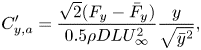 $$\begin{gather} {C^{\prime}_{y,a}} = \frac{{\sqrt 2 ({F_y} - {{\bar{F}}_y})} }{{0.5\rho DLU_\infty ^2}} \frac{y}{{\sqrt {{{\bar{y}}^2}} }}, \end{gather}$$
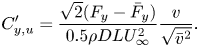 $$\begin{gather}{C^{\prime}_{y,u}} = \frac{{\sqrt 2 ({F_y} - {{\bar{F}}_y})} }{{0.5\rho DLU_\infty ^2}}\frac{v }{{\sqrt {{{\bar{v}}^2}}}}. \end{gather}$$
 Figure 14 reports the variation of the fluctuating lift coefficient amplitude along with the time average of its decomposed components,  ${C_{y,a}} (= \overline {C_{y,a}^{\prime }})$ and
  ${C_{y,u}} (= \overline {C_{y,u}^{\prime }})$, with the reduced velocity, and the variation of the phase difference (
 $\phi$) between the
  $y$ displacement and the lift force, computed using Hilbert transform as
 \begin{equation} \phi = {\phi _{{F_y}}} - {\phi _y}. \end{equation}
Figures 14(a) and 14(c) show the behaviour of the lift force coefficient and corresponding decomposed parts with the phase difference for the offset slit cases ( $\alpha = - {30^ \circ }$ and
  $\alpha = + {30^ \circ }$). Figure 14(b) depicts the same for the no-slit case, which is analysed to set a reference. For the no-slit case, the peak of the lift coefficient is observed at
  ${U_r} = 4$, corresponding to the oscillation amplitude jump between the IB and LB (figure 13b). The decomposed force component in phase with the acceleration (
 ${C_{y,a}}$) shows the jump at this reduced velocity, while the component in phase with the velocity (
 ${C_{y,u}}$) still indicates a net transfer from the fluid to the body. With a further increase in the reduced velocity, the total lift coefficient drops in the LB of amplitude response showing a decreased net transfer from the fluid to the body, causing reduced cylinder oscillations. For the case of
  $\alpha = - {30^ \circ }$, the peak of the lift coefficient and the component indicating fluid inertia (
 ${C_{y,a}}$) is observed at
  ${U_r} = 4.5$, which represents the peak oscillation amplitude at the end of the IB (or at the beginning of the LB in figure 13a). The component
  ${C_{y,u}}$ is mostly negative until
  ${U_r} \leq 4.5$, and changes sign for higher reduced velocities. It indicates that the net transfer is from the body to the fluid for this case in IB; hence, the peak oscillation amplitude is relatively lower than in the no-slit case. The jump in the phase between the cross-flow force and the oscillation amplitude coincides with the peak of
  ${C_{y,a}}$, although the peak of the component
  ${C_{y,u}}$ is shifted a little to a higher reduced velocity. Thus, for the
  $\alpha = - {30^ \circ }$ case, the cylinder oscillates with a phase difference (between the force and the oscillation amplitude) of
  ${0^ \circ }$ during the IB, and it switches to
  $180^\circ$ for the LB.
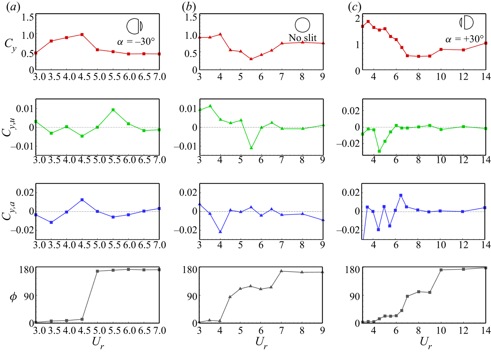
Figure 14. Variation of the lift coefficient ( ${C_y}$) and its corresponding component in phase with velocity (
 ${C_{y,u}}$) and displacement (
 ${C_{y,a}}$), and the phase difference between the lift and the
  $y$ displacement for different slit-offset cases: (a)
  $\alpha = - {30^ \circ }$, (b) no-slit case and (c)
  $\alpha = + {30^ \circ }$;
  ${m^*} = 10$,
  $\zeta = 0.02$,
  ${Re} = 500$.
Furthermore, figure 14(c) reports the force decomposition and the phase dynamics for the  $\alpha = + {30^ \circ }$ case. The lift coefficient drops continuously for
  ${U_r} > 4$, while the net energy transfer from the body to the fluid occurs (pertaining to the negative
  ${C_{y,u}}$ values). The phase difference between the force and oscillation amplitude shows the phase difference close to
  $0^\circ$ until
  ${U_r} = 4$ and increases during the IB. The peak of
  ${C_{y,a}}$ is observed at
  ${U_r} = 7$, corresponding to the phase jump of
  $90^\circ$ between the force and amplitude response. A relatively constant lift coefficient and, hence, constant oscillation amplitude is observed for the range of reduced velocities (
 $7 \leq {U_r} \leq 9$) in figure 13(c), for which the phase difference is close to
  $90^\circ$. After
  ${U_r} = 9$, the sudden drop in amplitude is related to the jump in the phase difference from
  $90^\circ$ to
  $180^\circ$. The force coefficient and its components remain relatively constant for the higher reduced velocities with a phase jump of
  $180^\circ$.
4.4. Implications in energy harvesting and power extraction
Vortex-induced vibration has recently attracted much attention for its applications in harvesting clean, renewable and economical energy. The energy generation from oscillatory motion via electromagnetism dates back to the era of Nikola Tesla's inventions. Recently, Soti et al. (Reference Soti, Thompson, Sheridan and Bhardwaj2017, Reference Soti, Zhao, Thompson, Sheridan and Bhardwaj2018) investigated a more straightforward way to utilize the cylinder's VIV oscillations to harness the electrical power by employing a coil-magnet arrangement. In their experimental study they fixed the magnet on the cylinder axis and placed the cylinder inside the conducting coil. As the flow flows over the cylinder, the cylinder oscillates transversely, inducing the eddy currents in the coil if connected to a resistive load. These eddy currents exert the repulsive force opposing the movement of the cylinder and can be numerically modelled as the additional damping.
Figure 15(a) depicts the variation of the non-dimensional average power extracted over the range of reduced velocities for two different slit-offset angles ( $\alpha = + {30^ \circ }$ and
  $\alpha = - {30^ \circ }$) and compares it with the no-slit case. The extracted power increases linearly with the reduced velocity due to the increasing oscillation amplitude in the IB. The peak power is achieved at the end of the IB. As the oscillation amplitude starts to drop in the LB with the increase in the reduced velocity, the extracted power also decreases. We observe that the peak power for the case of the no slit occurs at a reduced velocity of 4.5 and is comparable to the peak power obtained for the
  $\alpha = + {30^ \circ }$ case. The peak power for the
  $\alpha = - {30^ \circ }$ case is achieved at the reduced velocity of 4.5 but is minimum due to suppressed oscillations, making it non-suitable for energy extraction applications. Although the peak extracted power is achieved at the higher reduced velocity for the
  $\alpha = + {30^ \circ }$ case, but stays at a wider range of the reduced velocities (
 $5 \leq {U_r} \leq 8$).
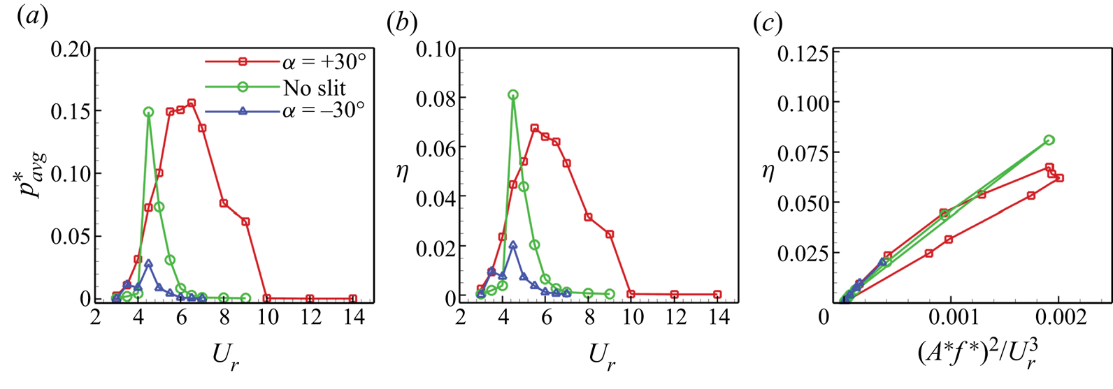
Figure 15. Effect of slit-offset angle on the harnessed power: (a) non-dimensional average extracted power, (b) power extraction efficiency and (c) variation of power extraction efficiency against the combined VIV parameter ( ${m^*} = 10$,
  $\zeta = 0.02$,
  ${Re} = 500$).
Furthermore, figure 15(b) computes the energy transfer ratio (or the power extraction efficiency) for the three cases. It follows the same trend: the energy transfer ratio is a function of the average extracted power and oscillation amplitude. Figure 15(b) explains the effectiveness of the slit offset towards the front stagnation point for the energy harvesting applications via the distribution of the power extraction efficiency over the reduced velocities. The clean cylinder (no-slit case) exhibits a higher energy transfer ratio, but that behaviour is confined to a lower range of reduced velocities. While for the  $\alpha = + {30^ \circ }$ case, although the peak efficiency is lower than the no-slit case, the energy extraction range of the high extraction efficiency is largely improved. This makes the
  $\alpha = + {30^ \circ }$ case preferable among others, especially for the application in energy harvesting. Past literature on the VIV of a cylinder reports the combined effect of the mass and damping on the energy, but we have analysed it independently. For this, we have utilized a combined parameter,
  ${({A^*}{f^*})^2}/U_r^3$. If all the other parameters are fixed, figure 15(c) indicates a linear dependence of the energy transfer ratio on this parameter. The slope of these curves are almost identical, but the peaks are at different locations due to the difference in the maximum oscillation amplitude.
To summarize, the present study assesses the flow field associated with the elastically mounted slit cylinder at a Reynolds number of 500. The three-dimensional simulations are performed for different slit-offset locations to develop a basic understanding of the underlying physics. The flow features have been assessed using computational techniques, such as flow visualization techniques, fast Fourier transform spectrum, phase dynamics and the decomposition of the forces into pressure and viscous parts. These methods explore various aspects of flow and suggest that the slit offset is a simple but powerful tool from the VIV perspective. Furthermore, the behaviour of the slit offsets is studied over the range of reduced velocities for the complete closure of the problem.
5. Conclusion
The present study numerically investigates the flow-induced vibrations of a circular cylinder at a Reynolds number equal to 500, bounded to oscillate in a transverse direction only. The impact of the asymmetric placement of the normal slit on the phenomenon of VIVs, previously studied in the absence of the cylinder's motion, has been analysed over a wide range of slit-offset angles. The present analysis is essentially based on three-dimensional simulations. First, three-dimensional simulations were performed on a fixed reduced velocity of 5 to assess the effect of asymmetric slit placement via flow visualization techniques. Then, the behaviour is further confirmed over a wide range of the reduced velocities covering different amplitude response branches for the complete closure of the problem. The last section deals with the implications of the slit cylinder on energy harvesting applications. The principal findings of this work are summarized as follows.
Oscillation amplitude versus the slit-offset angle: the cylinder's flow-induced oscillations are analysed for the slit placement from  $\alpha = - {30^ \circ }$ (corresponding to the slit placement near the rear stagnation point) up to
  $\alpha = + {30^ \circ }$ (corresponding to the slit placement near the front stagnation point). The cylinder exhibits the suppressed oscillations for the negative values of the slit-offset angles. The cylinder oscillations over the entire negative value range of the slit-offset angle are observed to be in a
  $180^\circ$ phase difference with the lift force. The close observations of the flow snapshots for the complete oscillation cycle show that the slit sheds one pair of vortices resembling the 2S type of vortex shedding. Placing the slit towards the front side results in a drop in the phase difference to lower values close to zero. The cylinder shows the increased oscillation amplitude with a relatively lower oscillation frequency. Also, the vortices are shed closer to the leeward side of the cylinder with a much wider wake behind the cylinder. The velocity signal across the slit's top and bottom ends (for all slit offsets) shows the alternate suction of the flow from the boundary layer from one end and blowing it to the main flow from the other end. This suction and blowing phenomena for the case of the positive values of the slit-offset angle is the strongest among other cases and shows the out-of-phase behaviour among the top and bottom end's velocity signals. The frequency spectrum of the probe velocity signal at the slit openings matches well with the cylinder's oscillation frequency. At the same time, higher harmonics are also observed for the slit at
  $\alpha = + {30^ \circ }$, representing the shedding of small-scale structures from the slit.
Reduced velocities, force decomposition and phase dynamics: the slit cylinder shows the two-branch amplitude response (i.e. the IB and LB over the entire range of the reduced velocities. The UB is absent for this mass-damping ratio ( ${m^*}\zeta = 0.2$) at a Reynolds number of 500. The frequency spectrum shows the multifrequency response outside the lock-in resulting in the beating-like oscillation amplitude response and follows the Strouhal law. The cylinder with the slit-offset angle
  $\alpha = + {30^ \circ }$ oscillates with high oscillation amplitudes over a wider range of reduced velocities, while a narrow range of high oscillation amplitudes is observed when the slit is placed at negative slit-offset angles. The lift force coefficient is decomposed into two components (in phase with acceleration and the oscillation velocity). The phase dynamics reveal that the change in phase difference between the lift force and the oscillation amplitude is associated with the peak of the decomposed component in phase with the displacement (representing the fluid inertia). The cylinder's higher oscillation amplitude for the
  $\alpha = + {30^ \circ }$ case over a wide range of reduced velocities (
 $7 \leq {U_r} \leq 9$) is related to the phase difference of
  $90^\circ$ between the lift and the displacement. As the phase difference switches to
  $180^\circ$, the oscillation amplitude reduces to almost zero.
Impact of slit offset on power extraction and energy harvesting: the cylinder oscillations are utilized to harvest energy using the coil-magnet arrangement based on the principle of electromagnetism. The power extraction behaviour of the offset slits is compared with the no-slit case. Owing to the suppressed oscillation amplitude, the placement of the slit towards the rear stagnation point results in the low power extraction capability making this case non-preferable for energy harvesting applications. The no-slit case shows the maximum energy transfer ratio, which occurs at the end of the IB and the start of the LB. Placing the slit towards the front stagnation point improves the energy harvesting behaviour of the cylinder. The higher energy transfer ratio values are observed over a wide range of reduced velocities, making it a suitable choice for adopting it for energy harvesting applications. The energy transfer ratio shows a linear dependence on the combined parameter,  ${({A^*}{f^*})^2}/U_r^3$.
Supplementary movies
Supplementary movies are available at https://doi.org/10.1017/jfm.2023.479.
Acknowledgements
The authors would like to acknowledge the National Supercomputing Mission (NSM) for providing the computational resources of ‘PARAM Sanganak’ at IIT Kanpur, which is implemented by C-DAC and supported by the Ministry of Electronics and Information Technology (MeitY) and the Department of Science and Technology (DST), Government of India. The authors would also like to acknowledge the IIT-K Computer Center (www.iitk.ac.in/cc) for providing the resources to perform the computation work.
Funding
This research received no specific grant from any funding agency, commercial or not-for-profit sector.
Declaration of interests
The authors report no conflict of interest.
Data availability statement
The data that support the findings of this study are available upon reasonable request.
Author contributions
All authors contributed equally to conceptualization, analysing data and reaching conclusions, and in writing the paper.
Appendix A. Domain independence study
We have performed the convergence study on the domain size length downstream of the cylinder for the case of the 1-DOF VIV at the reduced velocity of 5 with the slit-offset angle of  $+30^{\circ }$ (corresponding to the strongest vortex shedding and the maximum oscillation amplitude among all other cases). The results are depicted in figure 16 below and summarized in table 3. Here,
  $L/D$ corresponds to the domain length after the cylinder's centre.
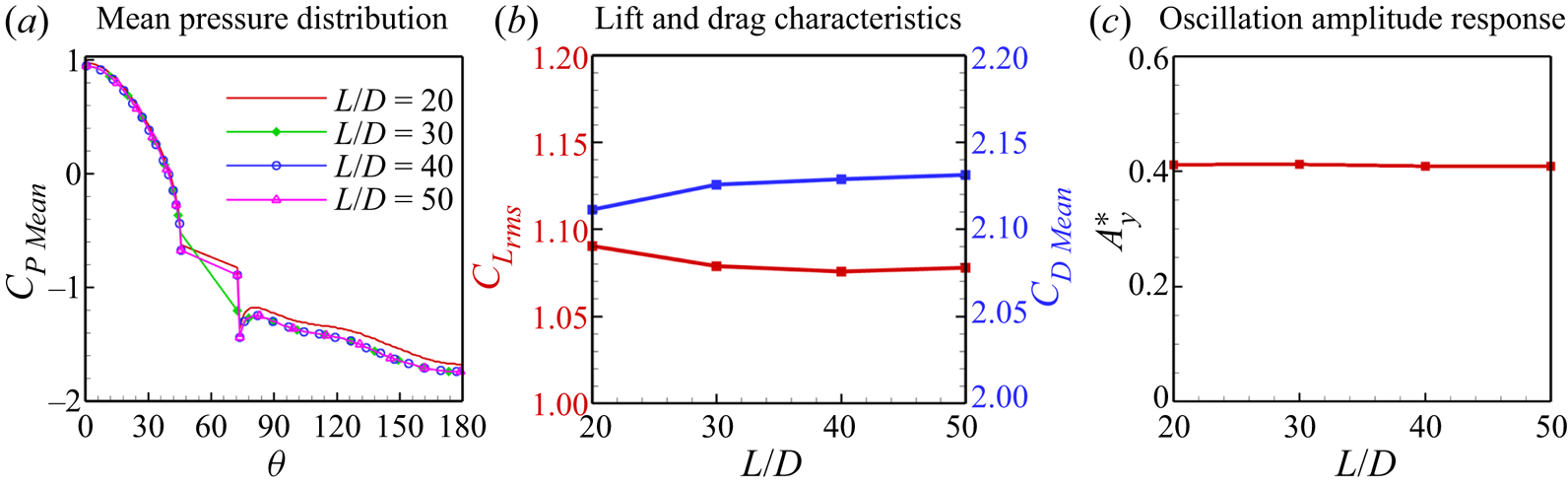
Figure 16. Domain independence study for the 1-DOF VIV slit cylinder: mean pressure distribution over the cylinder surface, the lift and drag characteristics for different domain length, and the VIV oscillation amplitude response;  ${m^*} = 10,{U_r} = 5,\zeta = 0.02,{Re} = 500,s/D = 0.2,\alpha = + {30^ \circ }$.
Table 3. The domain convergence study for the downstream length behind the cylinder (values in bold show the selected grid).
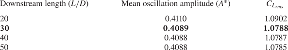
From figure 16 we can see that the mean pressure distribution of the cylinder's surface is almost identical for the domain lengths ( $L/D$) 30, 40 and 50. Also, the difference between the lift and drag coefficients for the successive domain lengths is negligible after the domain length of 30. Hence, the authors are confident that the domain length of
  $L/D = 30$ is sufficient to perform such a study.
Appendix B. Calculation of GCI
We take grid 3 as the base grid and approximate the error in grid 4 compared with grid 3 from the Richardson error estimator, defined by
 \begin{equation} E_1^{fine} = \frac{{{\varepsilon _{43}}}}{{1 - r_{43}^o}}. \end{equation}
The error in grid 2, compared with the solution of grid 3, is approximated by the coarse-grid Richardson error estimator, which is defined as
 \begin{equation} E_2^{coarse} = \frac{r^o{{\varepsilon _{32}}} }{{1 - r_{32}^o}}, \end{equation}
where  $r$ is the grid refinement ratio between the two consecutive grids defined as
 \begin{equation} {r_{i + 1,i}} = \frac{{{h_{i + 1}}}}{{{h_i}}}. \end{equation}
 The error ( $\epsilon$) is estimated from the solutions of two consecutive grids by
 \begin{equation} {\varepsilon _{i + 1,i}} = \frac{{{f_{i + 1}} - {f_i}} }{{{f_i}}}. \end{equation}
The GCI, which accounts for the uncertainty in the Richardson error estimator, is calculated for a fine grid and coarse grid as
 $$\begin{gather} GC{I_{fine}} = {F_s}|E_1^{fine}|, \end{gather}$$
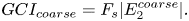 $$\begin{gather}GC{I_{coarse}} = {F_s}|E_2^{coarse}|. \end{gather}$$
Before using the Richardson extrapolation for GCI, we have also checked for the convergence conditions as
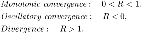 \begin{align} & \textit{Monotonic}\ \textit{convergence}: \quad 0 < R < 1, \notag\\ & \textit{Oscillatory}\ \textit{convergence}: \quad R < 0, \notag\\ & Divergence: \quad R > 1. \end{align}
Here  $R$, the convergence ratio, is defined as
 \begin{equation} R = \frac{{{\varepsilon _{i,i - 1}}} }{{{\varepsilon _{i + 1,i}}}}. \end{equation}
 Furthermore, to calculate the order of accuracy, the  $L_2$ norm of the errors between grids is calculated as
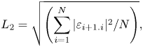 \begin{equation} {L_2} = \sqrt {\left( {\sum_{i = 1}^N {|{\varepsilon _{i + 1.i}}{|^2}/N} } \right)}, \end{equation}
where  $N$ is the total number of grid points considered for the calculation of the
  $L_2$ norm. Figure 3(c) depicts the
  $L_2$ norm against the grid spacing
  $h$ on a log-log scale. Further, the slope of the
  $L_2$ norm is compared with the theoretical slope of order 2. The order of accuracy (or the slope of the
  $L_2$ norm) is found to be 1.927. This value is used for GCI calculations of different grids. Also, the value of
  $R$ confirms the monotonic nature of convergence for the oscillation amplitude, as can be seen in table 2.


 Open access