


1. Introduction
In biomedical applications, microrobotic systems show great potential, especially in tasks related to manipulating cells [Reference Chen, Zhou, Zhang, Cao, Wang and Ma1], mechanical cell characterization, and cell sorting [Reference Boukallel, Gauthier, Dauge, Piat and Abadie2, Reference Diouf, Sadak, Gerena, Mannioui, Zizioli, Fassi, Boudaoud, Legnani and Haliyo3]. Their potential is especially valuable for exploration and intervention in confined environments [Reference Sugimoto and Nagasawa4], such as the use of soft crawling robots within micron-scale spaces [Reference Di, Zhang, Wen and Ren5]. Direct manipulation of objects as small as 50 nanometers to 10 micrometers [Reference Gerena, Legendre, Molawade, Vitry, Régnier and Haliyo6, Reference Zhang, Kimkes and Heinemann7] is conducted by Optical Tweezer (OT). On the other hand, the microscale domain brings its set of challenges. Aspects such as gravity become secondary, while other factors, such as adhesion forces, come into play. These forces might cause objects to stick to microrobotic tools, making the manipulation process more complex [Reference Gerena8]. Furthermore, while the intricacy of microobject manipulation demands precision, most micromanipulation platforms only provide manual control, lacking automation or sensory feedback. Moreover, unlike the development of a control scheme in large-scale robotic applications such as in visual servoing of a mobile robot manipulator [Reference Sanchez-Lopez, Marin-Hernandez, Palacios-Hernandez, Rios-Figueroa and Marin-Urias9], achieving 3-D closed-loop control remains elusive in the microscale domain [Reference Zhang10].
OT stands out as an interesting technique, particularly in the context of precise manipulation and assessment of mechanical properties of cells [Reference Zhang and Liu11]. One forthcoming aspect of OT is their ability to accurately perform precise motions without physical contact. This inherent capability enhances their attractiveness for various applications. OT’s precision and multi-point control capabilities could redefine intricate procedures such as in-vitro fertilization, introducing a new level of accuracy and control in the manipulation of delicate biological samples [Reference Ebrahimi, Bi and Khalil12]. However, while direct manipulation using lasers in OT offers precise control, it also carries the risk of photodamage to cells. An alternative is to employ microrobots for indirect cell handling, minimizing potential harm [Reference Gerena8].
The driving idea of using an optical microrobot for biological manipulation is to avoid direct exposure of samples to the laser beam. Microrobots are used as intermediate tools to act on cells, for transport, or mechanical stimulation. These microrobots are inert structures exhibiting spherical appendices. These appendices are trapped by the laser beam, and their force can be modeled as a 3-D force vector. To control the 6 degrees of freedom (DOF) of a rigid body in 3-D space, forces must be applied at three distinct, non-aligned points. Therefore, to achieve full 6-DOF motion control of the microrobot, at least three independent trapping points (TPs) are required, with each trap imposing a unique 3-D spatial constraint.
For this purpose, using a single laser beam through an active optical path with adequate elements, one can quickly switch the beam from one TP to the other, creating independent and parallel traps at diverse locations. This technique is called ’time-shared optical tweezers’ [Reference Curtis, Koss and Grier13, Reference Gerena, Régnier and Haliyo14]. Recent research has shown a high interest in the simultaneous trapping and manipulation of micron-sized samples [Reference Liang, Yan, Wang, Li, Cai, He, Yao and Lei15, Reference Zhang, Lu, Fu, Min, Yuan and Zhang16]. Manual manipulation, on the other hand, can be time-consuming and difficult since microrobots require many traps. These issues can be overcome by automating the identification and tracking of the microrobot and its TPs and measuring three-dimensional microrobot orientation. This information can then loop through the visual-servoing control scheme for automated trajectory control as implementing low-level closed control contributes to the overall stability improvement in both automated and semi-automated tasks. Applications that require targeted delivery, such as sperm cell injection, could be a useful interest [Reference Nauber, Goudu, Goeckenjan, Bornhäuser, Ribeiro and Medina-Sánchez17].
A camera is essentially necessary equipment for any experimental OT setup. Thus, it is the most accessible sensor option. The utilization of deep learning in computer vision has recently surfaced as a field significantly influencing medical research in microscale domain [Reference Sadak, Saadat and Hajiyavand18]. This is due to its superior capability to analyze complex visual input in real time. Deep learning models, as opposed to standard image processing approaches [Reference Sadak, Saadat and Hajiyavand19], learn and extract important features from raw data on their own, yielding more accurate and efficient results, especially in dynamic environments [Reference Nauber, Hoppe, Robles and Medina-Sánchez20]. Numerous research studies have derived advantages from applying deep learning within the microrobotic domain. CNNs and a long short-term memory cell were implemented to formulate a depth regression model aimed at estimating the 3-D position of the microrobot with sub-micron precision [Reference Grammatikopoulou and Yang21]. Exploration of detecting and tracking diverse configurations of microrobots extended to the utilization of different imaging systems, including magnetic resonance imaging (MRI) [Reference Tiryaki, Demir and Sitti22] and ultrasound imaging (US) [Reference Botros, Alkhatib, Folio and Ferreira23]. Nevertheless, the MRI and US imaging modalities typically impose constraints on real-time visual-servoing capabilities due to their operation at relatively low frequencies. Specifically, the visual servoing of a microrobot operation based on MRI requires a minimum frequency of 10 Hz, which is ten times greater than what has been achieved thus far, as shown in [Reference Tiryaki, Demir and Sitti22, Reference Tiryaki, Erin and Sitti24]. In a current study, a microscopic camera was utilized for microrobot and TPs localization in OT [Reference Ren, Keshavarz, Anastasova, Hatami, Lo and Zhang25]. Their methodology relies on a customized YOLOv4-tiny model for microrobot localization, incorporating the ConvNext block for feature extraction. To determine the trap position, they implemented a machine-learning method that identifies ellipses through arc-support groups and the k-means algorithm. Notably, the identification and sorting of individual traps and microrobots, as well as the orientation of the microrobot, have not been addressed in their study.
On the other hand, depth and orientation estimations play a pivotal role in effectively manipulating microrobotic systems. One of the intrinsic challenges faced in these estimations is the difficulty of accurately determining them from a sole image. This arises from the inherent loss of 3-D spatial information during the image-capturing phase [Reference Grammatikopoulou and Yang21]. While traditional methods have leaned on handcrafted features built upon focus measurements, recent advancements highlight the potential of neural networks [Reference Zhang, Lo, Zheng, Bai, Yang and Lo26]. Specifically, feature maps developed by neural networks present a broader and more generalized correlation between the image in focus and its specific depth value or orientation angle [Reference Grammatikopoulou and Yang27]. This observation leads us to explore deep learning-based techniques to construct digital video microscopy for microrobots, accounting for their diverse poses. However, estimating orientation introduces complexities beyond depth estimation. Notably, the space concerning orientation estimation is not bound by Euclidean norms; it operates within the framework of a Riemannian manifold [Reference Grammatikopoulou and Yang28]. This poses a significant challenge, as accurately estimating the pose from a single image is difficult due to the complex and overlapping orientations that microrobots can assume. Given these constraints, employing advanced deep learning algorithms could be a promising option to better address the intricate spatial interactions involved in microrobot pose estimation.
In our study, an explainable deep learning-based framework is proposed to accurately detect and track the microrobots and TPs while measuring the in-plane and out-of-plane orientation of the microrobot, which can be fully used as sensory feedback to control the microrobot orientation and trajectory.
2. Methodology
2.1. Experimental setup
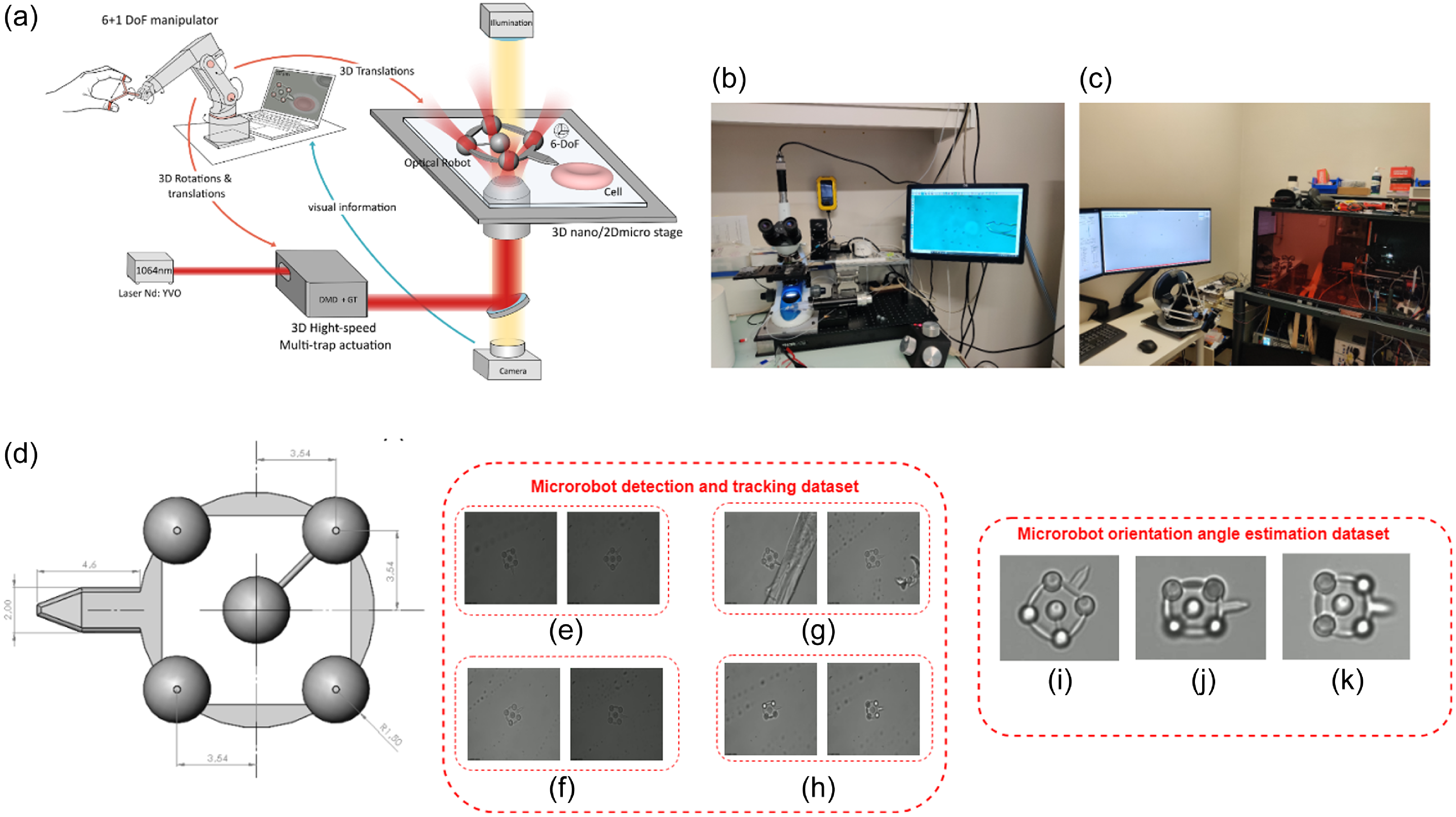
The experimental setup included three primary components: an infrared laser, passive optical elements such as mirrors and beam splitters, a 3-D multi-trap actuation system [Reference Gerena, Régnier and Haliyo14], and robot-assisted stages. The microrobot, which has four optical handles for TPs and allows for complete 6-DoF actuation, was built using two-photon polymerization and IP-Dip resin (Nanoscribe Photonic Professional). Finally, an operator’s 6-DoF joystick (Omega7) was employed to control the location of the microrobot. A custom-designed inverted microscope (Olympus UPlanFLN 40x, NA 1.3, oil immersion) is employed in the data preparation phase. Images are acquired using a high-speed Basler camera (ace-2-a2A1920-160umPRO) with a frame rate of up to 168 fps and a resolution of 659 x 494 pixels. This camera is paired with 3W LED illumination transmitted through a long-pass dichroic mirror. Figure 1a illustrates an overview of our experimental system.
Outline of our experimental configuration and approach to data preparation. (a) Setup for collecting microrobot data using an optical micromanipulation platform. (b) Microrobots transfer using a micro pipette in an optical microscope. (c) Optical tweezer (OT) setup and input device to record data. (d) Computer-aided design model of the microrobot in $\mu m$
. (e) Sample microrobot tracking and TPs localization dataset collection at random rotation in image plane. (f) At different brightness level. (g) At noisy micro-environment. (h) At various trapped conditions. (i) Sample 3-D microrobot orientation estimation dataset collection cases at (
$\mu m$
. (e) Sample microrobot tracking and TPs localization dataset collection at random rotation in image plane. (f) At different brightness level. (g) At noisy micro-environment. (h) At various trapped conditions. (i) Sample 3-D microrobot orientation estimation dataset collection cases at ( $48.6^\circ$
,
$48.6^\circ$
, $1.2^\circ$
,
$1.2^\circ$
, $15.76^\circ$
), (j) at (
$15.76^\circ$
), (j) at ( $3.4^\circ$
,
$3.4^\circ$
, $-36.6^\circ$
,
$-36.6^\circ$
, $8.2^\circ$
), and (k) at (
$8.2^\circ$
), and (k) at ( $0^\circ$
,
$0^\circ$
, $0^\circ$
,
$0^\circ$
, $-31.2^\circ$
).
$-31.2^\circ$
).
2.2. Dataset preparation procedure
In microrobotics, acquiring accurate and high-quality data is an intricate and essential procedure. Unlike other domains where datasets are readily available to the public, microrobotics is a niche, and its dataset development is still in the early stages. The data for this study was collected at the Sorbonne University, Institute of Intelligent Systems and Robotics Laboratory (ISIR), Paris. For our dataset, the OT setup enabled us to control and observe the movements of the microrobots under various conditions, providing a rich data source. Our dataset was separately collected for 3-D microrobot orientation estimation, microrobot tracking, and TP localization. Our microrobot detection and orientation angle estimation dataset is publicly available.Footnote 1
The chosen microrobot for this study has a distinct shape, and its precise dimensions can be seen in Fig. 1d. It has five TPs, and the perpendicular distance from center TP to its edge is 3.54 $\mu m$
. Once the microrobots are selected, they are carefully picked up using a micropipette from their resting position in the Petri dish as depicted in Fig. 1b. This delicate procedure requires immense precision to ensure the microrobots are not damaged during transfer. The picked microrobots are then relocated to the OT setup. This environment allows for a more focused observation of the microrobots. Notably, each microrobot has five distinct TPs essential for the subsequent data collection process. The input device becomes instrumental with the microrobots positioned in the OT setup, as shown in Fig. 1c. This device facilitates precise control over the orientation of the microrobots. By manipulating the input device, we can alter the orientation of the microrobots, ensuring that a diverse range of data is captured for analysis. In detail, the microrobot’s trajectory during the preparation process, beginning with the input device, specifying the intended orientation of the robot, and then utilizing the robot’s inverse kinematic model. This is critical in determining the required trap positions communicated precisely to the optical path. We implement an open-loop system where the robot follows the input while acknowledging that this technique may create some accuracy constraints. This pipeline highlights the procedures needed, clearly showing how the microrobot’s orientation is managed.
$\mu m$
. Once the microrobots are selected, they are carefully picked up using a micropipette from their resting position in the Petri dish as depicted in Fig. 1b. This delicate procedure requires immense precision to ensure the microrobots are not damaged during transfer. The picked microrobots are then relocated to the OT setup. This environment allows for a more focused observation of the microrobots. Notably, each microrobot has five distinct TPs essential for the subsequent data collection process. The input device becomes instrumental with the microrobots positioned in the OT setup, as shown in Fig. 1c. This device facilitates precise control over the orientation of the microrobots. By manipulating the input device, we can alter the orientation of the microrobots, ensuring that a diverse range of data is captured for analysis. In detail, the microrobot’s trajectory during the preparation process, beginning with the input device, specifying the intended orientation of the robot, and then utilizing the robot’s inverse kinematic model. This is critical in determining the required trap positions communicated precisely to the optical path. We implement an open-loop system where the robot follows the input while acknowledging that this technique may create some accuracy constraints. This pipeline highlights the procedures needed, clearly showing how the microrobot’s orientation is managed.
2.2.1. Microrobot orientation estimation dataset
Using the OT setup, the microrobot was strategically positioned within the observation zone, ensuring the entire structure was visible and within the focal plane. High-resolution images of the microrobot were captured at various orientations in 3-D. Each image was timestamped to ensure that the progression and transformation of the microrobot’s orientation over time could be analyzed. To deepen our understanding, more than 34,000 image frames were captured. These frames not only encompassed the visual details of the microrobot but also recorded the desired orientation angles from the input device.
Moreover, the positions of all the tPs were registered for every frame. This comprehensive dataset includes separate image sets for rotations along each axis in X, Y, and Z. In particular, the dataset shows instances where the microrobot rotates around a single axis, two axes simultaneously, and unrestricted rotations in a 3-D environment. For in-plane rotations (around the X-axis), the rotational range spanned from $-120^\circ$
to
$-120^\circ$
to $+120^\circ$
. Conversely, the out-of-plane rotations (around the Y and Z axes) fluctuated roughly between
$+120^\circ$
. Conversely, the out-of-plane rotations (around the Y and Z axes) fluctuated roughly between $-40^\circ$
and
$-40^\circ$
and $+40^\circ$
. These limits of rotations are determined by the limit of the working space of the 3-D actuation system [Reference Gerena, Régnier and Haliyo14]. Subsets of this data are used to train and validate our deep learning models. Our dataset for this orientation estimation model comprises a total of 15,287 image frames, of which 70% (10,700) was used for training, 20% (3058) was used for validation and 10% (1529) was used for the test set. For this training, we employed a more restricted range of out-of-plane rotations, which is
$+40^\circ$
. These limits of rotations are determined by the limit of the working space of the 3-D actuation system [Reference Gerena, Régnier and Haliyo14]. Subsets of this data are used to train and validate our deep learning models. Our dataset for this orientation estimation model comprises a total of 15,287 image frames, of which 70% (10,700) was used for training, 20% (3058) was used for validation and 10% (1529) was used for the test set. For this training, we employed a more restricted range of out-of-plane rotations, which is $-35^\circ$
to
$-35^\circ$
to $+35^\circ$
, for the logical comparison we conducted with baseline models.
$+35^\circ$
, for the logical comparison we conducted with baseline models.
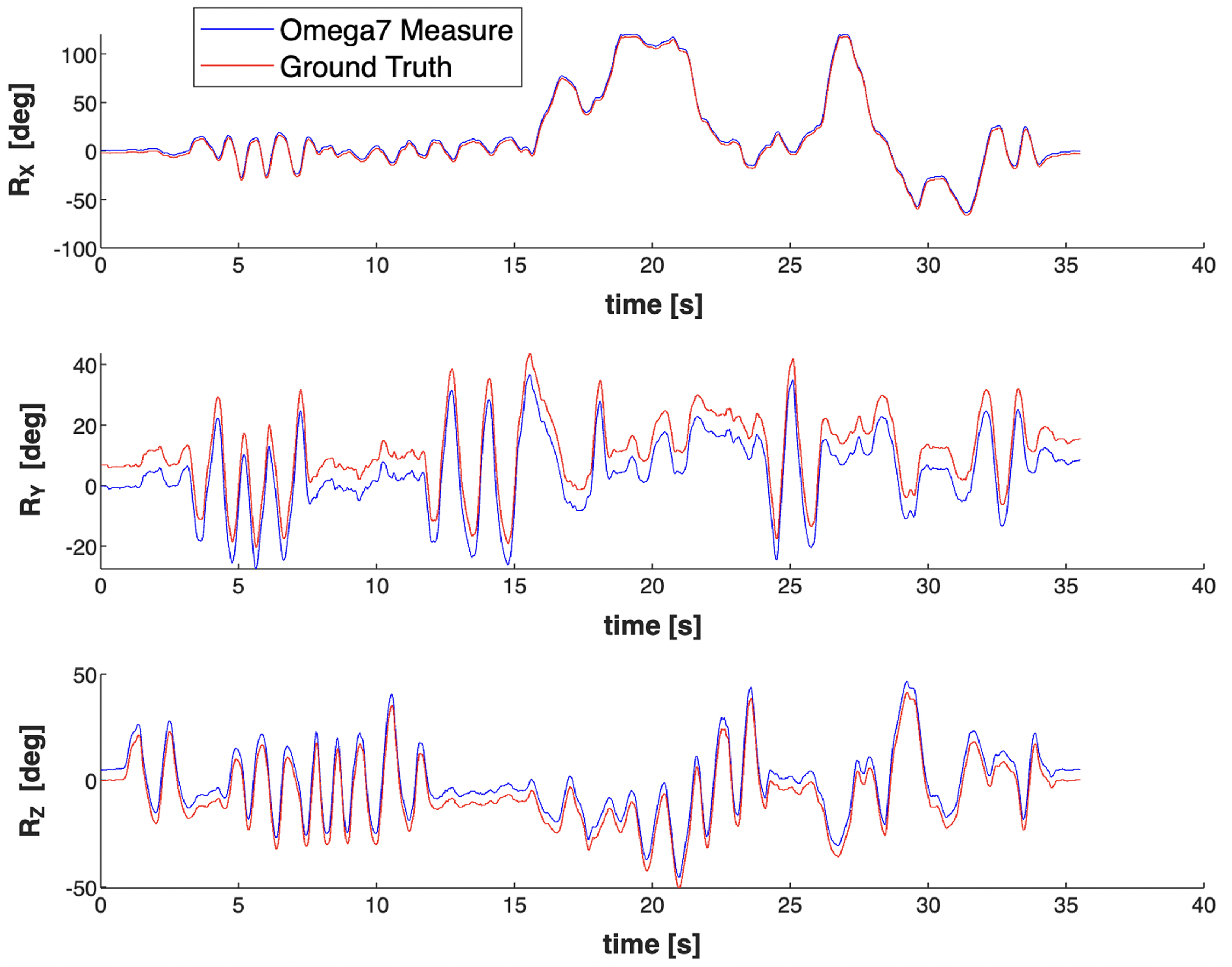
However, certain challenges were encountered during data acquisition. For instance, even when the microrobot was being rotated along a particular axis, the input device occasionally detected rotations around the other two axes. A strategy was followed to prevent this limitation and derive a highly accurate ground truth. Instead of relying solely on the input device for angular measurements, the 3-D positions of the tPs were utilized. By doing so, the orientations could be extracted more accurately. In addition, wrist angles given by the 6-DoF joystick are the feedback provided by the input device that aids in the more precise calculation of the microrobot’s rotational angles. Omega7 feedback from the input device was recorded to determine rotation angles in the X, Y, and Z axes. The approach used to calculate angles from tPs is based on a transformation function. This function employs a Least-Squares Rigid Motion method using singular value decomposition [Reference Klema and Laub29]. It’s designed to align two sets of corresponding points to minimize the mean squared distance between them. The function computes a rotation matrix for each image frame from which we can find Euler angles. This visual comparison in Fig. 2 can provide insights into the precision and reliability of the captured orientation data. In conclusion, this dataset contributes rich visual data for microrobot orientations and provides a robust method for accurate orientation estimation using the 3-D positions of tPs. Fig. 1 i, j, and k shows the sample dataset used for orientation estimation at various positions.
2.2.2. Microrobot localisation and tracking dataset
We employed an in-house collected dataset encompassing 544 optical microrobot images to facilitate the training, validation, and testing processes for our algorithm designed for detecting and tracking microrobots and TPs. Before initiating the algorithm training, the entire dataset collected underwent pre-processing steps, including resizing to dimensions of 416 × 416 pixels. Our dataset was partitioned into three subsets: a training set comprising 70% of the dataset, a validation set with 10% of the dataset, and a testing set including 20% of the dataset. This division was executed randomly 20 times using Fisher-Yates shuffle algorithm. The objective is to guarantee that each set maintains a representative distribution of images across various testing settings to prevent biased decisions. Our in-house collected dataset includes efficient diversity, such as at different image plane rotations in Fig. 1e, at different brightness levels in Fig. 1f, in noisy micro-environment in Fig. 1g, and different trapped conditions in Fig. 1h. Introducing these conditions into the dataset aims to validate the algorithm’s robustness and ability to perform effectively across diverse experimental conditions.
Comparison between orientations computed from the input device (Omega7 measure) and kinematic transforms (ground truth).
2.3. YOLOv7 and DeepSORT integration for microrobot and TPs detection and tracking
This section will briefly overview the DeepSORT algorithm and YOLOv7. Here, we used a common detection algorithm, YOLOv7 [Reference Wang, Bochkovskiy and Liao30] for detection, and DeepSORT algorithm [Reference Wojke, Bewley and Paulus31] to provide a unique ID for each microrobot and TPs. For YOLOv7, extended efficient layer aggregation network (E-ELAN) [Reference Gao, Lu, Li, Mottaghi and Kembhavi32], model scaling for concatenation-based model [Reference Dollár, Singh and Girshick33], and re-parameterization [Reference Ding, Chen, Zhang, Huang, Han and Ding34] were used to achieve optimal accuracy. The YOLOv7 backbone comprises Convolutional, Batch Normalization, SiLU activation (CBS), E-ELAN, and Maxpool-1 (MP1) modules. The CBS module comprises convolutional processes, batch normalization, and SiLU activation functions, facilitating effective feature extraction. Maintaining the ELAN structure, the E-ELAN module significantly improves learning capacities. This is achieved by guiding various computing units responsible for feature extraction to learn a broader range of features while preserving the original gradient route. The MP1 structure incorporates pooling and convolution as down-sampling methods. This integration allows the network to intelligently determine the most suitable down-sampling technique based on the prevailing circumstances.
The head of the YOLOv7 model employs the Feature Pyramid Network architecture, which incorporates the PANet concept. This network has several CBS blocks. Furthermore, the head consists of a structure called Spatial Pyramid Pooling and Convolutional Spatial Pyramid Pooling (Sppcspc), as well as an E-ELAN and MaxPool-2 (MP2). The Sppcspc structure is critical in expanding the network’s perceptual field. This is accomplished by merging a convolutional spatial pyramid structure with the spatial pyramid pooling structure. The structure of the MP2 block closely resembles that of the MP1 block, with a minor adjustment to the number of output channels. Its role encompasses both down-sampling and feature extraction. Ultimately, the head of the YOLOv7 model generates the output as the final prediction.
In evaluating YOLOv7 performance, box loss, objectness loss, and classification loss were assessed over 100 epochs. The sum of YOLOv7 loss served as a metric to quantify the disparity between the model’s predicted results and the ground truth, as indicated in Equation (1).
 \begin{equation} \text{loss} = l_{\text{bbox}} + l_{\text{object}} + l_{\text{classification}} \end{equation}
The box loss metric measures the method’s ability to accurately encompass the object with a predicted bounding box and locate its center. Objectness indicates the chance of identifying an object in a specific area of interest. In contrast, the classification loss measure assesses the algorithm’s ability to estimate the classification label for the recognized object correctly.
Moreover, mean average precision ( $mAP_{0.5}$
) and (
$mAP_{0.5}$
) and ( $mAP_{0.5:0.95}$
) were employed to evaluate the mAP across different IoU thresholds ranging from 0.5 to 0.95. Hence, Precision and Recall are measured based on true positive (TP), false positive, true negative, and false negative. The precision is calculated by dividing the total number of positive samples identified, regardless of whether correctly or incorrectly, by the number of positive samples correctly classified. The accuracy evaluates how accurately the model classifies a sample as positive, as represented in Equation (2).
$mAP_{0.5:0.95}$
) were employed to evaluate the mAP across different IoU thresholds ranging from 0.5 to 0.95. Hence, Precision and Recall are measured based on true positive (TP), false positive, true negative, and false negative. The precision is calculated by dividing the total number of positive samples identified, regardless of whether correctly or incorrectly, by the number of positive samples correctly classified. The accuracy evaluates how accurately the model classifies a sample as positive, as represented in Equation (2).
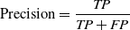 \begin{equation} \text{Precision} = \frac{TP}{TP + FP} \end{equation}
Recall quantifies the algorithm’s success in accurately recognizing positive instances, as expressed in Equation (3).
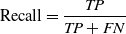 \begin{equation} \text{Recall} = \frac{TP}{TP + FN} \end{equation}
mAP is computed by averaging the precision of each class, determined by the area under the precision-recall curve, as depicted in Equation (4).
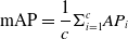 \begin{equation} \text{mAP} = \frac{1}{c}\Sigma _{i=1}^{c}AP_{i} \end{equation}
IoU quantifies how much the predicted bounding box aligns with the ground truth bounding box, which represents the manually labeled area that an object occupies in an image, as indicated in Equation (5).
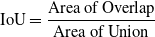 \begin{equation} \text{IoU} = \frac{\text{Area of Overlap} }{\text{Area of Union}} \end{equation}
Integrating YOLOv7 and DeepSORT to assign unique IDs to each detection enables complete automation control in our microrobotic system. This critical feature is notably absent in existing literature [Reference Ren, Keshavarz, Anastasova, Hatami, Lo and Zhang25]. DeepSORT (Deep Simple Online Realtime Tracking) represents an advanced object tracking algorithm that integrates a deep learning-based object detector with a tracking algorithm, aiming for improved accuracy by the inspiration of SORT (Simple Online and Real-Time Tracking) algorithm [Reference Bewley, Ge, Ott, Ramos and Upcroft35]. SORT utilizes the Kalman filter and the Hungarian algorithm to link object detections across successive frames. DeepSORT improves precision and accuracy by incorporating a deep neural network-based object detector. The DeepSORT algorithm combination with YOLOv7 provides a framework for detecting and tracking microrobots and TPs. The Hungarian algorithm is used to link detected microrobots and TPs across frames, taking into account the objects’ location as well as their appearance. The data association method includes an additional appearance metric obtained from pre-trained CNNs. This capability enables the re-identification of tracks even after prolonged periods of occlusion, where objects may temporarily disappear. When the state of position and velocity is checked, it is then adjusted considering the corresponding object appearance feature. Trajectories that stay unassociated with any identified objects for a predefined period or have confidence scores below a specific level are also eliminated from consideration. DeepSORT improves the original SORT algorithm by using appearance features, location, and motion information. This innovation results in more precise and robust object tracking, especially in objects’ occlusion or temporary disappearance. Overall, we selected YOLOv7 and DeepSORT for their optimal balance between detection accuracy and computational efficiency, making them well-suited for the real-time demands of our optical microrobotic system. These algorithms were chosen for their ability to provide precise and reliable tracking within the constraints of our experimental setup while providing robust performance with an affordable computational requirements.
2.4. Three-dimensional optical microrobot orientation estimation
To handle the dataset efficiently and conduct a successful training process, a custom dataset class, called the orientation dataset, is designed using PyTorch’s Dataset class. Certain pre-processing steps are essential before feeding images to the model. Here, we’ve employed a center crop to resize images to a standard size of 264 $\times$
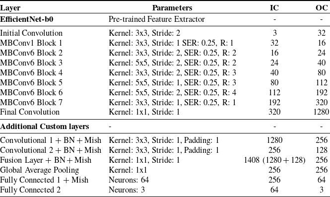
264 pixels, then convert them to PyTorch tensors. These transformations ensure that our model receives inputs of a consistent shape. All the image frames are labeled with their orientation angles around X, Y, and Z for a regression task. Our proposed model combines EfficientNet-b0 architecture with custom convolutional layers and a fusion layer enriched by the Mish activation function. Here, we present the block diagram of our proposed model architectural details as shown in Fig. 3 and the rationale behind each component choice, such as kernel size, squeeze-and-excitation ratio, and corresponding input and output channels as illustrated in Table I.
$\times$
264 pixels, then convert them to PyTorch tensors. These transformations ensure that our model receives inputs of a consistent shape. All the image frames are labeled with their orientation angles around X, Y, and Z for a regression task. Our proposed model combines EfficientNet-b0 architecture with custom convolutional layers and a fusion layer enriched by the Mish activation function. Here, we present the block diagram of our proposed model architectural details as shown in Fig. 3 and the rationale behind each component choice, such as kernel size, squeeze-and-excitation ratio, and corresponding input and output channels as illustrated in Table I.
Orientation estimation network parameters (SER = squeeze excitation ratio, R = repeats, IC = input channel, and OC = output channel).
The illustration of the proposed model architecture.
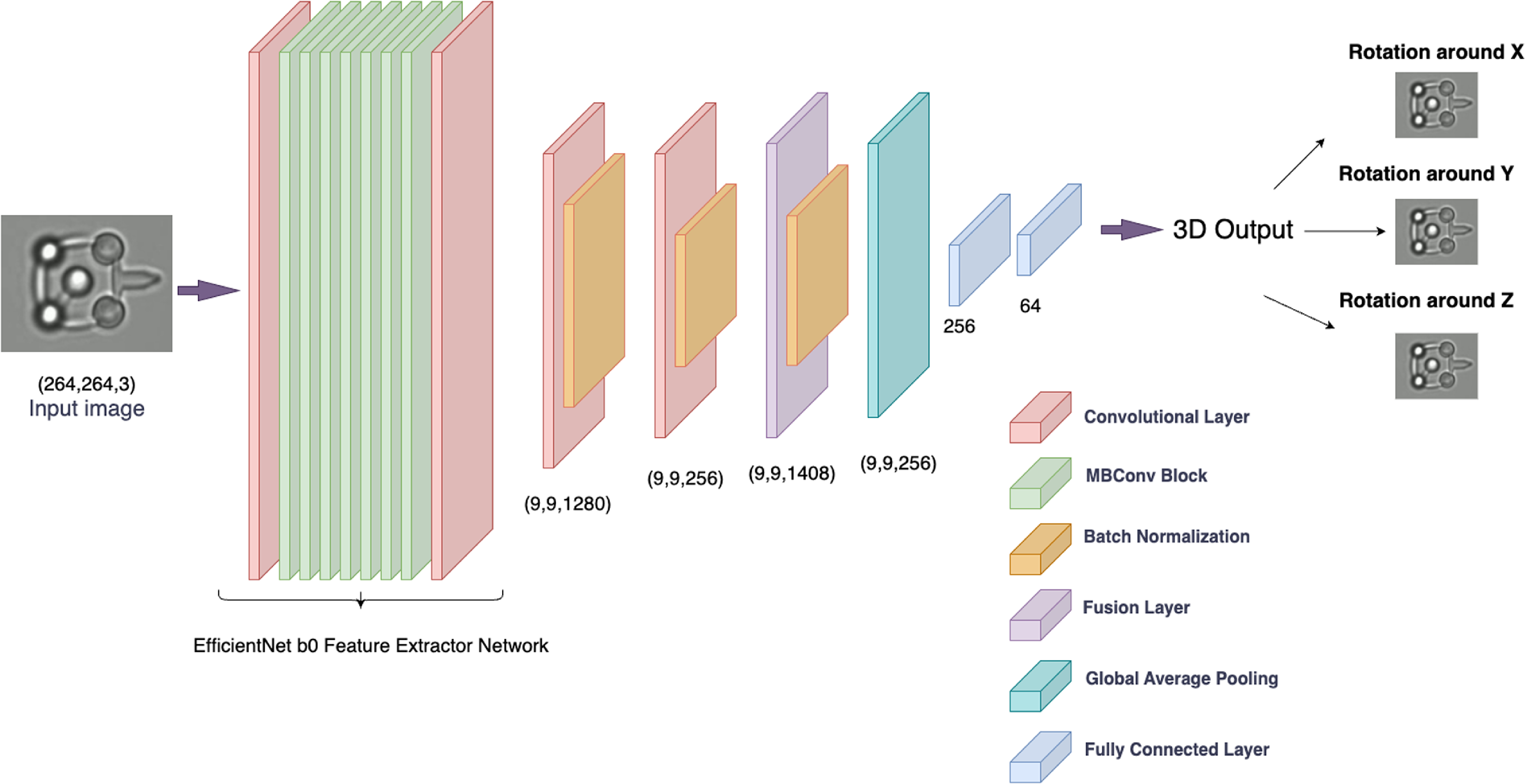
EfficientNet-b0 was recognized as one of the most efficient CNN architectures, offering an optimal tradeoff between accuracy and computational efficiency. It is the smallest variant in the EfficientNet family, pre-trained on a large ImageNet dataset, enabling it to extract rich and meaningful features from input images. It includes a series of models that have been carefully optimized for better performance with fewer parameters. It has been developed by scaling dimensions of depth, width, and resolution in a balanced manner, which provides enhanced performance without significantly increasing computational demand. This model comprises a series of Mobile Inverted Residual Blocks (MBConv) and convolutional layers. One advantage of adopting Mobile Inverted Residual Blocks is their ability to successfully handle the tradeoff between network depth and computational performance. These blocks use depthwise separable convolutions, which drastically reduce the number of parameters and computational cost when compared to typical convolutions. Furthermore, the inverted residual structure with linear bottlenecks keeps the feature representation rich and non-redundant, which improves the model’s capacity to learn complicated patterns while remaining efficient. The MBConv1 block is the initial block that helps extract low-level features from the input. It is followed by MBConv6 blocks, which are variants of MBConv blocks with an expansion factor of 6, indicating that the internal layers of the block expand the channel size by a factor of 6 before compression. These blocks have different kernel sizes, strides, and SER, allowing the network to learn diverse features at various spatial resolutions. Using EfficientNet-b0 as a feature extractor enables us to derive potent image representations, ensuring a robust foundation for our subsequent layers.
Following the feature extraction through EfficientNet-b0, the model introduces additional convolutional layers. The first convolutional layer takes the 1280-dimensional output from EfficientNet-b0, and applies a series of transformations including convolution, batch normalization, and the Mish activation function as shown in Equation (6), reducing the dimensionality to 256. The second convolutional layer further transforms the features, reducing the dimensionality from 256 to 128. The model then performs a feature fusion step, where the original features from EfficientNet-b0 and the transformed features from the second convolutional layer are concatenated along the channel dimension. This results in a combined feature map of dimension 1408, which is then passed through another convolutional layer (fusion) to reduce the dimensionality to 256 while integrating information from both feature sets.
The model then applies global average pooling (GAP) to the feature map. This technique averages out the spatial dimensions of each feature channel, effectively transforming the feature map from a three-dimensional tensor to a one-dimensional vector per feature channel. By converting the spatial information into a compact form, GAP significantly reduces the computational load for the subsequent fully connected layers, facilitating a more efficient learning process while preserving the essential feature information. The model concludes with two fully connected layers that transform the feature vector into the final output. The first fully connected layer(fc1) reduces the dimensionality from 256 to 64 and applies the Mish activation function. The Mish activation function is a relatively new activation function that has been shown to outperform traditional functions like ReLU in various tasks [Reference Misra36]. It’s a smooth function that can help adaptive learning features with its non-monotonic nature. The formula is given by Equation (6):
 \begin{equation} \text{Mish}(x) = x \times \text{tanh}(\text{softplus}(x)) \end{equation}
where the softplus function is a smooth approximation of the ReLU activation function [Reference Misra36]. Finally, the second fully connected layer(fc2) produces the final 3-D output of the model.
2.5. Fine-tuning hyperparameters
Effective hyperparameter tuning is critical for improving the performance of deep learning models. We intentionally chose to separate and handle the tuning procedures for various tasks in our study due to their fundamental complexities and interdependence. The nature of recognizing microrobots (using YOLOv7), tracking them (using DeepSORT), and understanding their orientation causes a variety of problems, each of which necessitates a unique strategy for optimization. Detection and tracking require parameters distinct from those required for orientation understanding. As a result of our methodology, we used numerous optimization approaches adapted to the individual needs of each task, fine-tuning the parameters to match the needs of that specific function. We aimed to achieve optimal performance for each task by identifying and addressing the particular requirements of microrobot and TP detection, tracking, and orientation estimation through task-specific tuning procedures. While our technique effectively addressed the individual requirements of each task and improved model performance, we recognize that a more integrated or sequential optimization strategy may provide a more unified solution and requires in-depth investigation.
2.5.1. YOLOv7 and DeepSORT hyperparameter optimisation
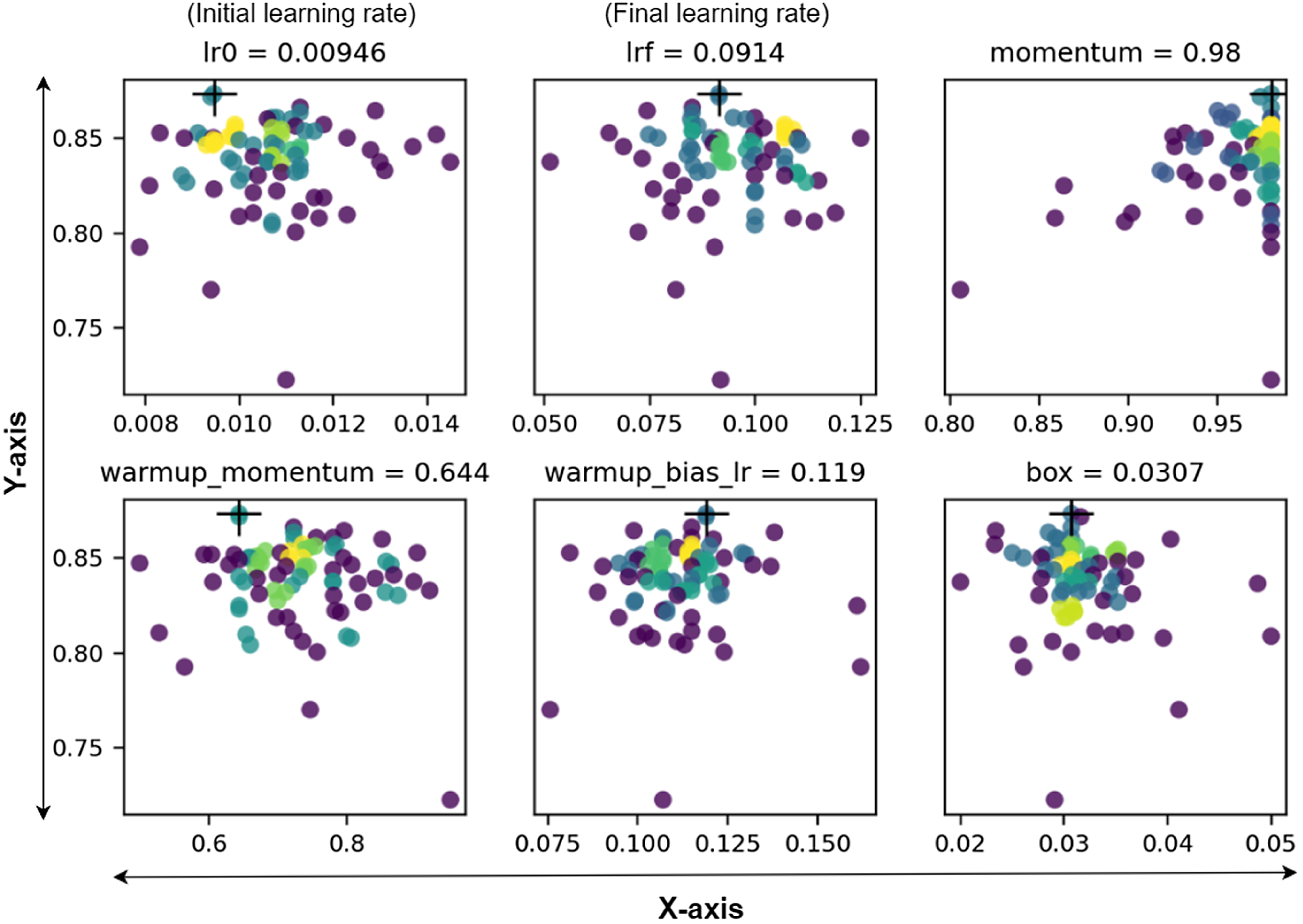
By applying the Genetic Algorithm (GA), which is mutation genetic operator, a heuristic optimization technique based on natural selection, we attempted to improve the YOLOv7 and DeepSORT models’ performance. The large parameter space of YOLOv7 includes makes optimization difficult. Our approach started using the standard YOLOv7 model’s default hyperparameters as a basic framework. These parameters were then specifically tuned to fit the characteristics of our microrobot dataset. Following the optimization, each model was trained and evaluated using an objective function. In this case, we used mAP@0.5, which served 10% of the weight, and mAP@0.5:0.95, which accounted for the other 90%. This methodology maintained consistency with the evaluation method we adopted for this study. Model selection was executed using the fitness score derived from the evaluation metrics to maximize the fitness score. Subsequently, these models underwent a mutation genetic operator, with an 80% probability of creating new offspring from two-parent models from all prior generations, where mutation introduced random perturbations. In total, we have conducted 50 generations to find our dataset’s most optimal configurations of the hyperparameters. The final hyperparameter for the YOLOv7 model was determined by choosing the iteration with the highest evaluation metric score. We effectively optimized all 30 hyperparameters for YOLOv7, illustrating its efficacy in enhancing overall detection accuracy. Figure 4 illustrates the hyperparameter tuning process employing GA.
An illustration of some of the main hyperparameter tuning procedures. The Y-axis represents the fitness score, the X-axis represents hyperparameter values, and higher concentrations are denoted by the yellow color code [Reference Sadak, Gerena and Haliyo37].
2.5.2. Microrobot orientation estimation model hyperparameter optimisation
For the hyperparameter tuning process for microrobot orientation estimation, we employed Optuna library, a state-of-the-art hyperparameter optimization framework [Reference Akiba, Sano, Yanase, Ohta and Koyama38]. Optuna uses various optimization techniques. The tree-structured Parzen estimator is a key method among them. This method helps effectively search the hyperparameter space to find the optimal values. It uses a probabilistic model to predict the next set of hyperparameters, leading to faster and more efficient optimization.
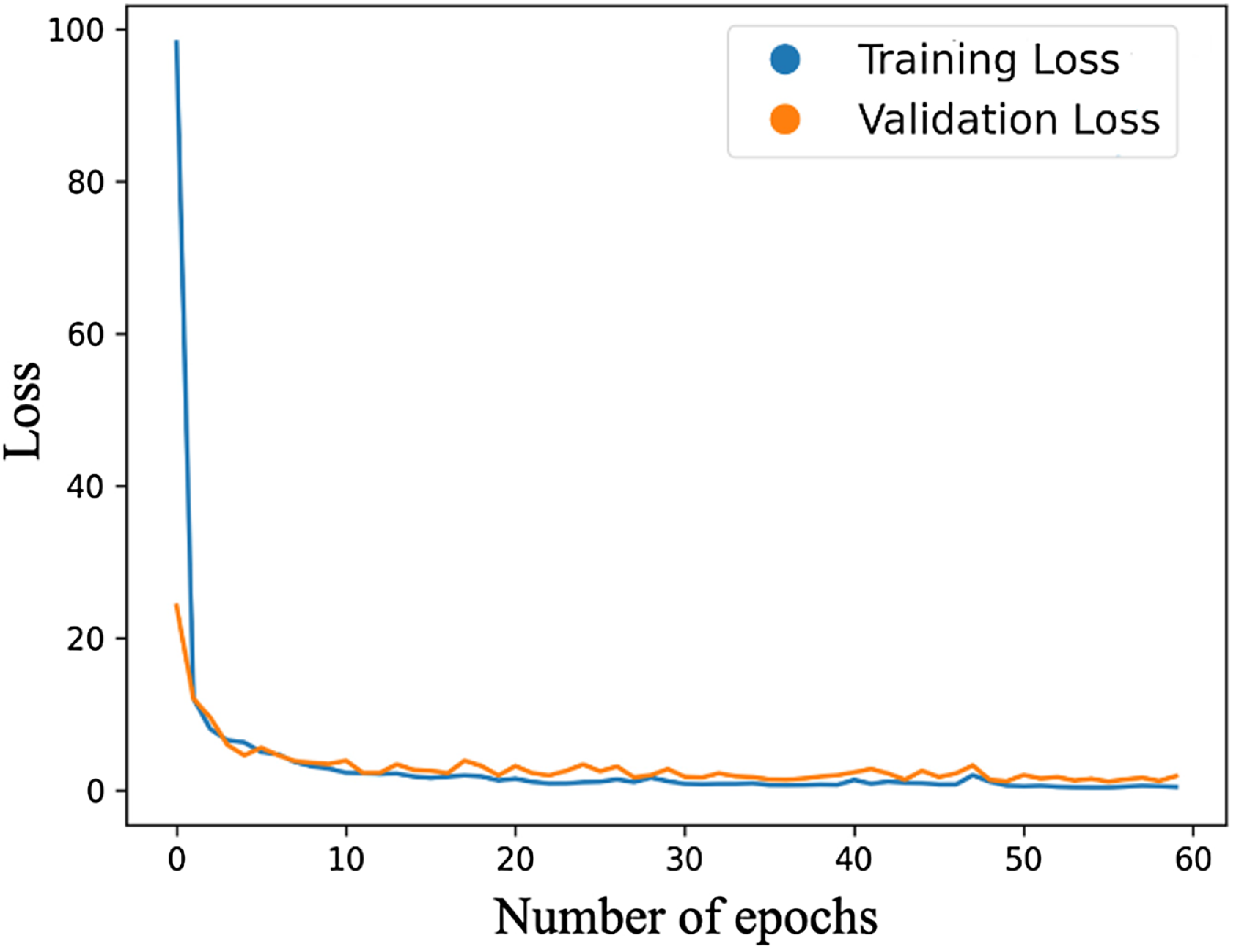
For this study, we conducted optimization over 50 trials, focusing primarily on three hyperparameters: batch size, learning rate, and momentum. These specific hyperparameters are selected because they substantially impact training dynamics. Essentially, the learning rate dictates the step size during optimization, influencing the model’s ability to converge to a solution; the momentum adds a factor of the previous update to the current one for faster convergence, and the batch size dictates the number of samples used in one forward/backward pass. Our code defines an ‘objective’ function, incorporating these hyperparameters into the training process, and computes a validation loss. By minimizing this validation loss, Optuna helps identify the most optimal hyperparameters. For the training configuration, a batch size of 64 is employed for training, while the testing is conducted with a batch size of 32. The learning rate is set to 0.0085, and the momentum value is adjusted to 0.90. The model undergoes training over 60 epochs, and the progression of loss over these epochs is illustrated in Fig. 5. All computational tasks were carried out on an NVIDIA Tesla V100 GPU.
Loss during training and validation versus number of epochs.
3. Results and discussion
3.1. Results of training and testing for detection of microrobots and TPs
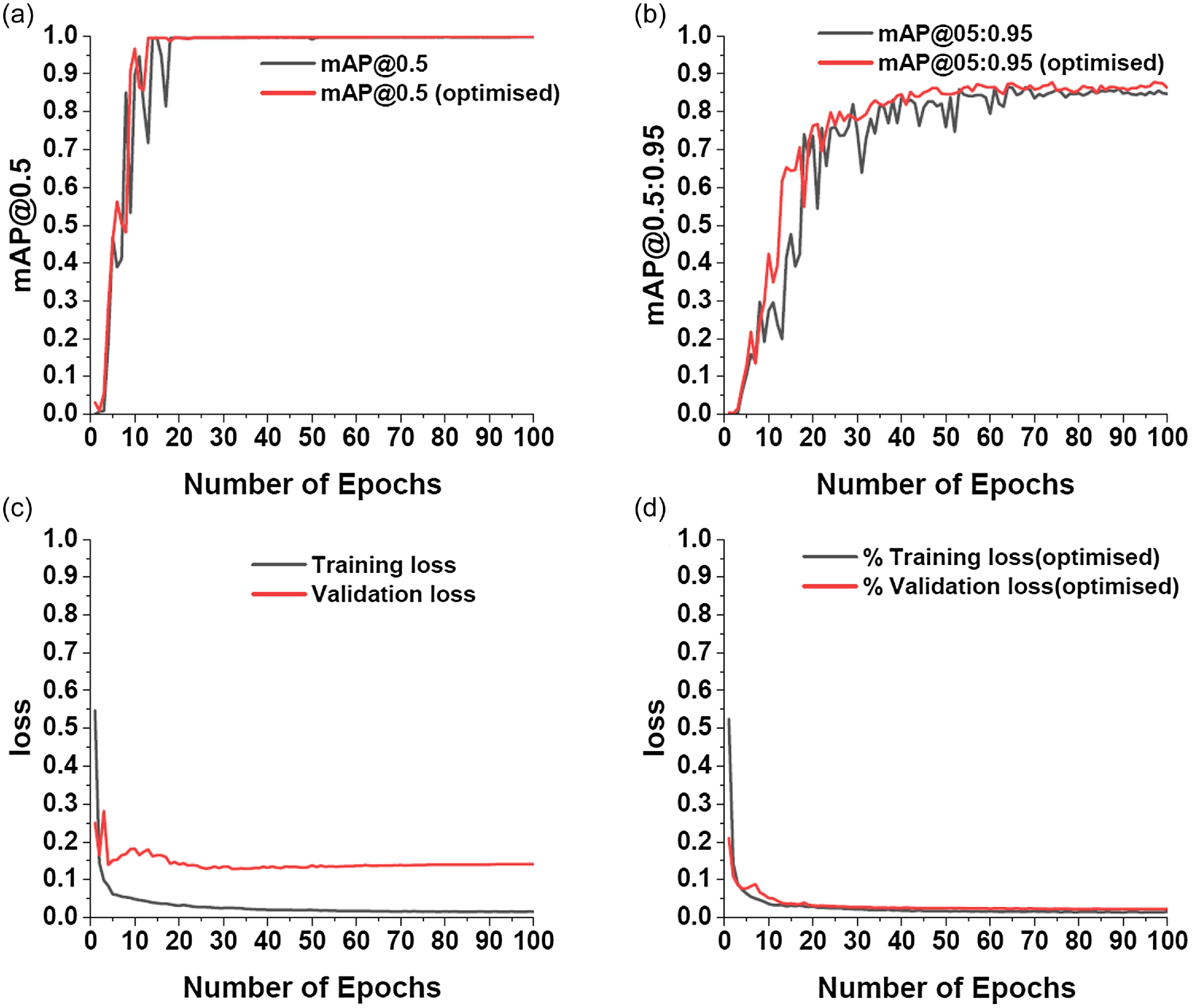
Figure 6 shows training results for detecting microrobots and TPs. Figures 6a and 6b provide a comparison of training accuracy (mAP@0.5 and mAP@0.5:0.95) between the optimized YOLOv7 and DeepSORT models. Optimizing both YOLOv7 and DeepSORT provides various benefits. Figures 6a and 6b show that our model outperforms the default YOLOv7 and DeepSORT models regarding both accuracy measures. The validation loss assesses the model’s capacity to generalize to new data, whereas the training loss indicates how well it learns from training data. As a result, the training and validation losses for the optimized YOLOv7 and DeepSORT models were significantly better matched in training and validation datasets. Over 100 epochs, our model obtained roughly $\sim$
88% mAP@0.5:0.95, compared to the default model’s
$\sim$
88% mAP@0.5:0.95, compared to the default model’s $\sim$
85% mAP@0.5:0.95.
$\sim$
85% mAP@0.5:0.95.
Performance evaluation of optimized YOLOv7 and DeepSORT model for 100 epochs based on: (a) mAP@0.5 (b) mAP@0.5:0.95 (c) training and validation loss for YOLOv7 and DeepSORT model. (d) training and validation loss for optimized YOLOv7 and DeepSORT model [Reference Sadak, Gerena and Haliyo37].
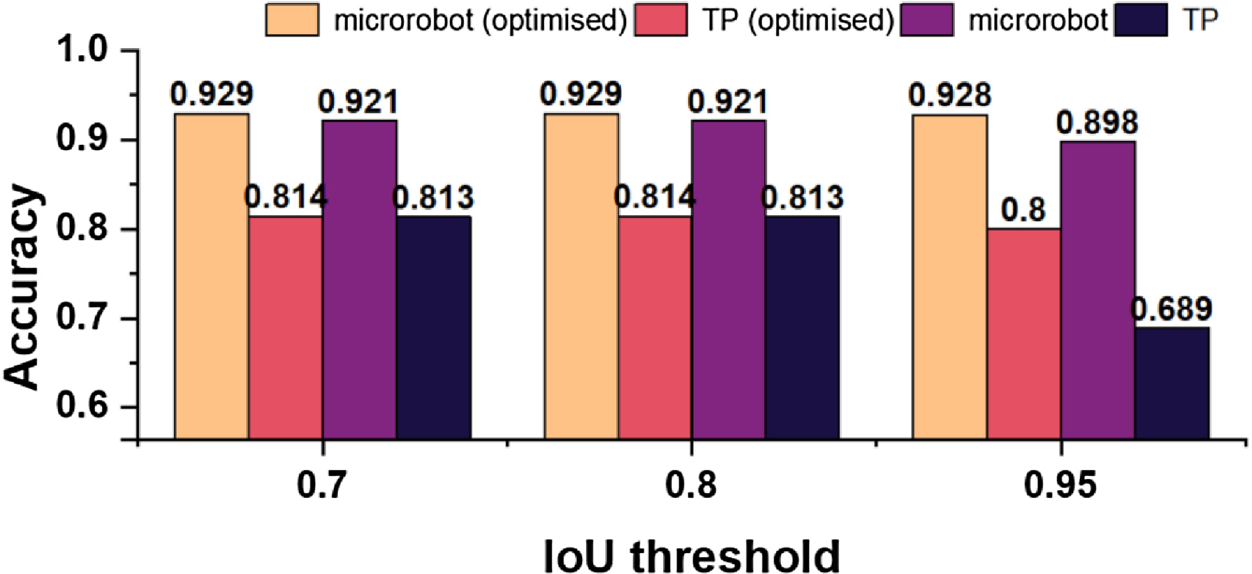
Accurate localization is required for completely automated control of microrobot positions. Figure 7 shows our test set, a fully independent dataset used to evaluate our method’s performance in recognizing microrobots and TPs. To assess the effectiveness of our optimized model, we established IoU thresholds of 0.7, 0.8, and 0.95, and assessed the corresponding detection accuracy. Figure 7 shows no significant changes in accuracy at 0.7 and 0.8 IoU thresholds across all models. However, at the 0.95 IoU threshold, our optimized model improved accuracy by about $\sim$
3% and
$\sim$
3% and $\sim$
11% for microrobot and TP detection, respectively.
$\sim$
11% for microrobot and TP detection, respectively.
3.2. Comparison of TPs detection performance
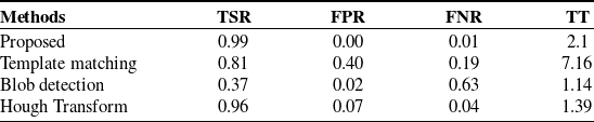
To show the effectiveness of our method, the most widely used circle detection methods, which are Template Matching [Reference Lewis39], Blob Detection [Reference Hinz40], and Hough Transform [Reference Nair and Saunders41] were selected. This would allow us to illustrate the robustness of the proposed method for TP detection considering commonly utilized potential circle detection methods. We ran a comparison analysis on 110 images that contained 550 TP labels. The evaluation focused on trapping time in seconds, which represents the time required to analyze all 110 images, trapping success rate, which measures the percentage of successful trapping events, false-positive rate, which measures the rate of incorrectly detected tPs, and false-negative rate, which measures the rate of missed tPs.
According to our findings in Table II, our model exhibited an accuracy of 99%, surpassing the closest competitor, Hough Transform, by 3%. Notably, despite including various noisy images with varying brightness levels in our test set, our model successfully identified the TPs in approximately 2 s with no false-positive detections. As a result, our technique performs well in settings that include visual distractions such as contamination or dust. Compared to the Hough Transform approaches, it identified 7% of the test data as false positives and just 4% as false negatives. Despite using several templates to increase the robustness of the Template Matching method, both Template Matching and Blob Analysis performed poorly in detecting TPs under diverse scene conditions. Table II shows that our deep learning framework outperforms previous approaches.
Comparison of TP detection methods.
Evaluation of the optimized YOLOv7 and DeepSORT model performance using different IoU thresholds in the test set [Reference Sadak, Gerena and Haliyo37].
3.3. Training and testing for microrobot orientation estimation
Evaluating the performance of deep learning models requires appropriate metrics that adequately capture the essence of the model’s estimations concerning the actual values. For our study, given that the output data represents angles in degrees, which inherently exhibits a circular nature, we’ve employed three key metrics: mean error, median error, and standard deviation (SD). Each metric, tailored to handle circular data, offers distinct insights into our model’s performance.
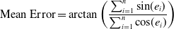 \begin{equation} \text{Mean Error} = \arctan \left (\frac{\sum _{i=1}^{n} \sin\!(e_i)}{\sum _{i=1}^{n} \cos\!(e_i)}\right ) \end{equation}
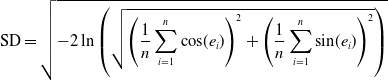 \begin{equation} \text{SD} = \sqrt{-2 \ln \left (\sqrt{\left (\frac{1}{n}\sum _{i=1}^{n} \cos\!(e_i)\right )^2 + \left (\frac{1}{n}\sum _{i=1}^{n} \sin\!(e_i)\right)^2}\right )} \end{equation}
where $e_i$
is the difference between the ground truth value and the estimated value for an image frame and
$e_i$
is the difference between the ground truth value and the estimated value for an image frame and $n$
is the sample size used for calculation.
$n$
is the sample size used for calculation.
We assess model performance on estimating angles, a unique data type due to its cyclical nature. For instance, a discrepancy of $359^\circ$
practically means just a
$359^\circ$
practically means just a $1^\circ$
error in the opposite direction. Standard metrics, hence, fall short. We have adapted the metrics calculations to cater to this circular data to measure our model’s accuracy effectively. Central to this adaptation is converting angular errors into their sine and cosine components and then applying trigonometric and statistical functions. By doing so, our metrics encapsulate the essence of the error distribution and ensure precision and reliability in understanding the model’s estimations. The choice of mean and median error, commonly used in state-of-the-art studies, is pivotal in checking the model’s accuracy. The standard deviation, on the other hand, offers insights into the consistency and reliability of our model.
$1^\circ$
error in the opposite direction. Standard metrics, hence, fall short. We have adapted the metrics calculations to cater to this circular data to measure our model’s accuracy effectively. Central to this adaptation is converting angular errors into their sine and cosine components and then applying trigonometric and statistical functions. By doing so, our metrics encapsulate the essence of the error distribution and ensure precision and reliability in understanding the model’s estimations. The choice of mean and median error, commonly used in state-of-the-art studies, is pivotal in checking the model’s accuracy. The standard deviation, on the other hand, offers insights into the consistency and reliability of our model.
The model was set to the training mode at the start of each epoch. The model estimates the orientation based on the input frames for every batch in our training data loader. The mean squared error between the predicted orientations and the ground truth is calculated. This error is back-propagated through the network to update the weights using the Adam optimizer. To monitor the model’s performance during training, the training loss was printed every 10 mini-batches. This continuous feedback allows for close monitoring of model behavior, ensuring no abrupt spikes in loss and the model is learning as expected. The proposed model’s estimation is compared to ground truth values on the test set, as shown in Fig. 8a.
Evaluation of model performance in the test set.
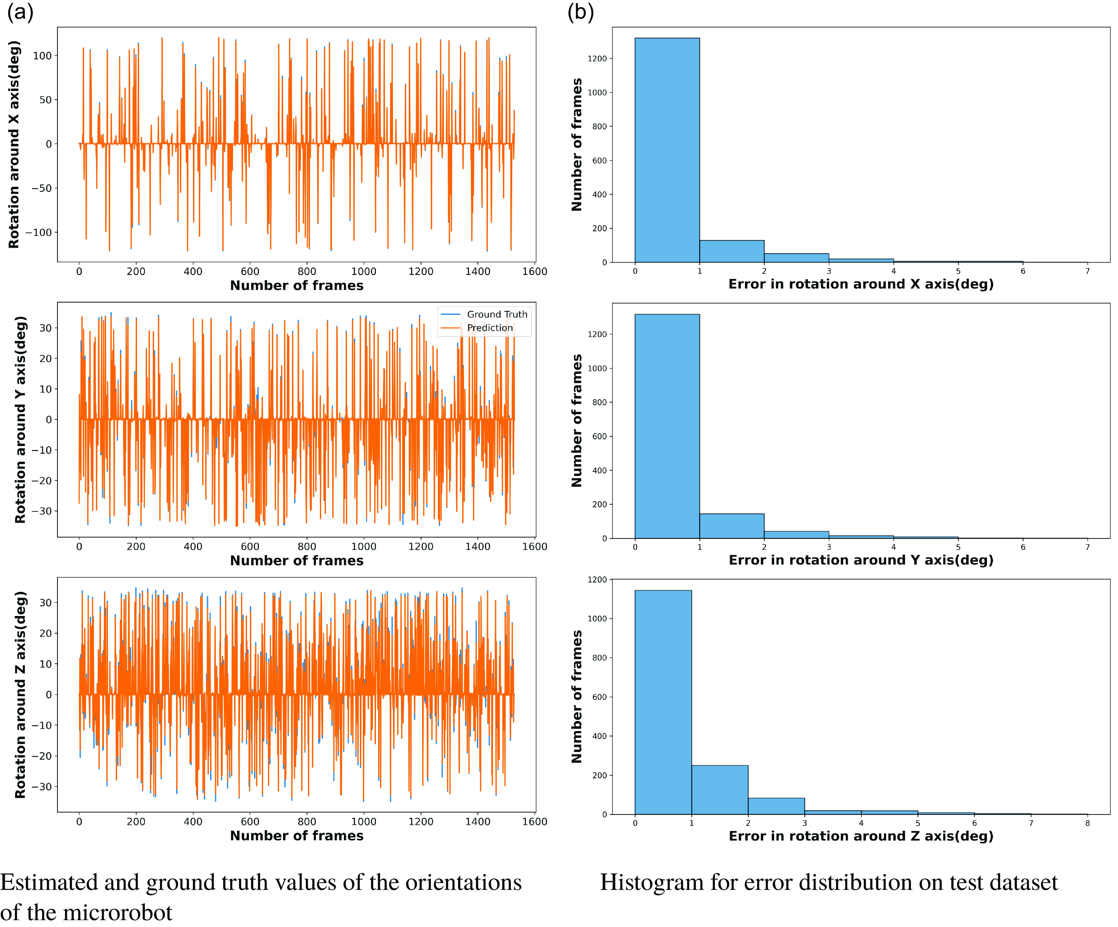
When examining the estimations made by our model, we employed the histogram representation of the error distribution. Through this, we can visualize and measure the accuracy of our model in predicting rotations across the three axes. The histogram representation provides a clear view of where the majority of our errors lie. A highlight from our results is that over 75 % of the errors across the image frames have a value between 0 and 1. This indicates the model’s high precision, as most of its estimation are extremely close to the ground truth, with a marginal error shown in Fig. 8b.
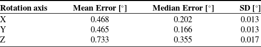
The model’s performance in predicting orientation around the X, Y, and Z axes is summarized in Table III, showcasing the mean error, median error, and standard deviation on the test dataset. The model showcases significant accuracy, especially considering the varying ranges of rotations. Despite having a wider range, the in-plane rotations have similar mean errors to the out-of-plane rotations, showing that the model can predict the 3-D orientations efficiently. Moreover, the consistently low standard deviations across all axes ensure that the model’s performance doesn’t vary wildly and remains consistent across multiple estimations.
Metrics for different axes on test dataset.
3.4. Experiment for microrobot orientation estimation on in-house dataset
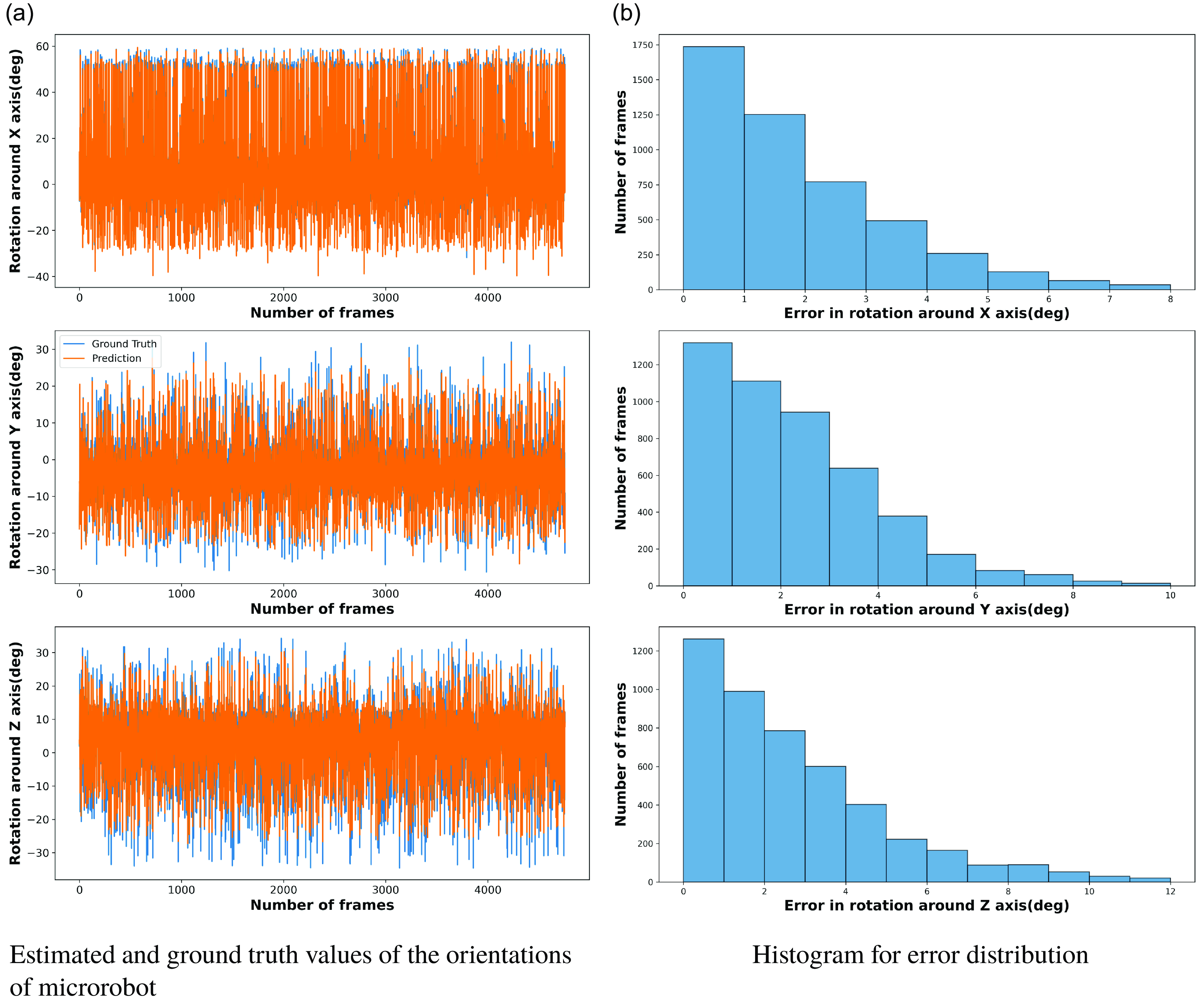
To demonstrate the efficiency and the generalization ability of our proposed microrobot orientation estimation pipeline, we analyzed the model’s performance on an in-house dataset comprising 4757 image frames aside from our test set. This in-house dataset is taken from the same imaging system but not seen by the model during the training process. Each frame in this in-house dataset showcases the microrobot executing rotations across all three axes simultaneously. Such a movement pattern is especially demanding for any predictive model, as it requires the simultaneous estimation of rotations about the roll, pitch, and yaw axes, each of which could influence the observed image in intricate ways. A visual comparison of the proposed model’s estimations versus the ground truth for this dataset is shown in Fig. 9a.
The histogram shows that more than 60 % of the estimations have errors ranging between $0^\circ$
to
$0^\circ$
to $2^\circ$
on the X-axis and
$2^\circ$
on the X-axis and $0^\circ$
to
$0^\circ$
to $3^\circ$
on the Y and Z-axis, as shown in Fig. 9b. This further reinforces the idea that the model performs consistently even on almost three times larger unseen data than the test dataset. The fact that most errors lie within this narrow range, especially considering the complexity and unfamiliarity of the in-house dataset, is evidence of the model’s robustness and generalization ability.
$3^\circ$
on the Y and Z-axis, as shown in Fig. 9b. This further reinforces the idea that the model performs consistently even on almost three times larger unseen data than the test dataset. The fact that most errors lie within this narrow range, especially considering the complexity and unfamiliarity of the in-house dataset, is evidence of the model’s robustness and generalization ability.
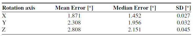
The performance of our proposed microrobot orientation angle estimation pipeline on the in-house dataset is summarized in Table IV. For the X-axis, which corresponds to in-plane rotations, the mean error on the in-house dataset is $1.871^\circ$
. Although this is a completely unseen dataset, an average error of approximately
$1.871^\circ$
. Although this is a completely unseen dataset, an average error of approximately $1.871^\circ$
, although higher than our test dataset results, still indicates the model’s ability to generalize. The median error, which provides a clearer view of the central tendency, is
$1.871^\circ$
, although higher than our test dataset results, still indicates the model’s ability to generalize. The median error, which provides a clearer view of the central tendency, is $1.452^\circ$
. This suggests that over half of the estimations have errors below
$1.452^\circ$
. This suggests that over half of the estimations have errors below $1.452^\circ$
. The standard deviation
$1.452^\circ$
. The standard deviation $0.027^\circ$
confirms consistency, indicating that most data points are closely clustered around the mean, with only small deviations.
$0.027^\circ$
confirms consistency, indicating that most data points are closely clustered around the mean, with only small deviations.
Performance evaluation of our proposed model for different axes on in-house dataset.
Evaluation of model performance on in-house dataset.
For out-of-plane rotations, for the Y-axis, the mean error is $2.308^\circ$
, while for the Z-axis, it’s slightly higher at
$2.308^\circ$
, while for the Z-axis, it’s slightly higher at $2.808^\circ$
. The median errors for Y and Z are
$2.808^\circ$
. The median errors for Y and Z are $1.956^\circ$
and
$1.956^\circ$
and $2.151^\circ$
, respectively. Again, these values being lower than the mean errors suggest that the model’s central performance remains tight, with larger errors in a few estimations pushing up the mean. The standard deviations for Y and Z are
$2.151^\circ$
, respectively. Again, these values being lower than the mean errors suggest that the model’s central performance remains tight, with larger errors in a few estimations pushing up the mean. The standard deviations for Y and Z are $0.032^\circ$
and
$0.032^\circ$
and $0.045^\circ$
, respectively, further reinforcing the model’s consistent performance across a diverse dataset.
$0.045^\circ$
, respectively, further reinforcing the model’s consistent performance across a diverse dataset.
3.5. Opening the black-box of the proposed pipeline
This section demonstrated the explainability of the proposed deep learning-based framework, including microrobot and TPs detection and tracking and microrobot orientation angle estimation. Since classification and regression are two different tasks, each model has undergone different explainability methods, which will be detailed in the following sections.
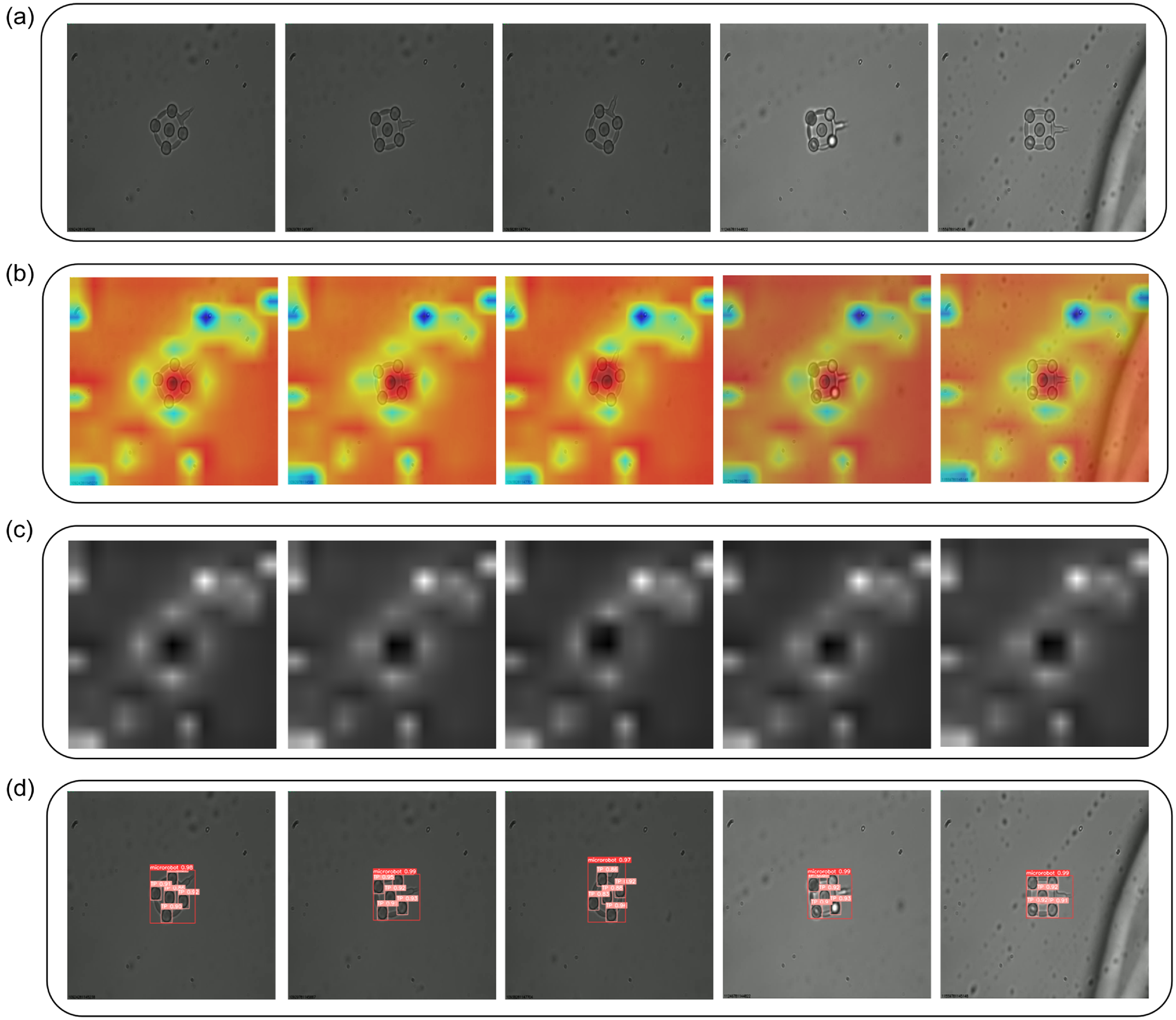
Explainability of the microrobot and TP localization using SCORE-CAM. (a) input image (b) scoreCam heatmap results (c) saliency maps (d) detection and tracking results for microrobot.
3.5.1. Explainability of microrobot and TPs detection and tracking
To better understand our proposed model and demonstrate how it performs better than other models when conducting microrobot and TPs detection and tracking, Score-CAM was employed [Reference Wang, Wang, Du, Yang, Zhang, Ding, Mardziel and Hu42]. Score-CAM is a powerful visualization tool that delivers critical insights into the inner workings of deep learning models, allowing for more intuitive and precise model interpretation. Score-CAM, in contrast to typical gradient-based approaches, does not use back-propagated gradients to identify relevant regions in an input image. Instead, it employs a novel two-stage technique. The first stage uses a CNN to produce activation maps from input images. These maps are then upsampled to fit the dimensions of the input image. The activation maps are pointwise multiplied with the input image and then normalized in the second stage. This normalization improves the model’s discriminative capabilities significantly. The CNN then processes the modified inputs with these activation map-based masks to generate scores specific to the target class. The strength of this method is its ability to identify and highlight the most relevant portions of an image for the model’s estimations, providing improved transparency and interpretability compared to standard gradient-based approaches.
As a result, in our method, Score-CAM was used by selecting our model’s final convolution layer, and the results were visually shown as heat maps in Fig. 10b, demonstrating the findings on five randomly selected microrobots under different locations. These heat maps help specialists analyze the precision of our model estimation, particularly regarding certain image regions associated with a specific class. They effectively emphasize the critical areas contributing to the model’s decision-making process. A careful analysis of the saliency maps obtained from each test image as shown in Fig. 10c reveals that our model consistently directs its attention on microrobots and TPs, highlighting its robust recognition of these elements. This increased transparency and insight into our model’s inner workings improves its explainability, bridging the gap between advanced deep learning techniques and practical implementations.
3.5.2. Explainability of microrobot orientation estimation
In this work, we employed SHAP (SHapley Additive exPlanations) to interpret the predictive model’s behavior in microrobot orientation detection. SHAP values are grounded in game theory and provide a robust framework for attributing the estimation output of the model to its input features. By employing SHAP values, we can visualize the impact of each pixel on the model’s estimation, offering insights into which features are deemed significant by the model. We calculate SHAP values using a gradient-based approach, which perturbs the input image and observes the change in estimations output. The resulting SHAP values are then mapped to the input space, producing visual explanations as illustrated in Fig. 11. The brighter regions in the SHAP visualizations correspond to areas with higher positive SHAP values, indicating greater importance in influencing the model’s estimation.
For the in-plane rotation estimation, the SHAP values highlight the end effector’s location as a critical determinant. It suggests the model significantly emphasizes the end effector’s position to infer the in-plane rotation angle. Conversely, for out-of-plane rotations, the SHAP values emphasize the TPs, excluding the central one, which becomes blurred due to the rotation. The model’s focus on these blurred areas indicates their importance in estimating the orientation. This is an interesting occurrence explaining the model decision-making process transparently while estimating the orientation angle.
Explainability of the microrobot orientation estimation model with input images and SHAP value images.
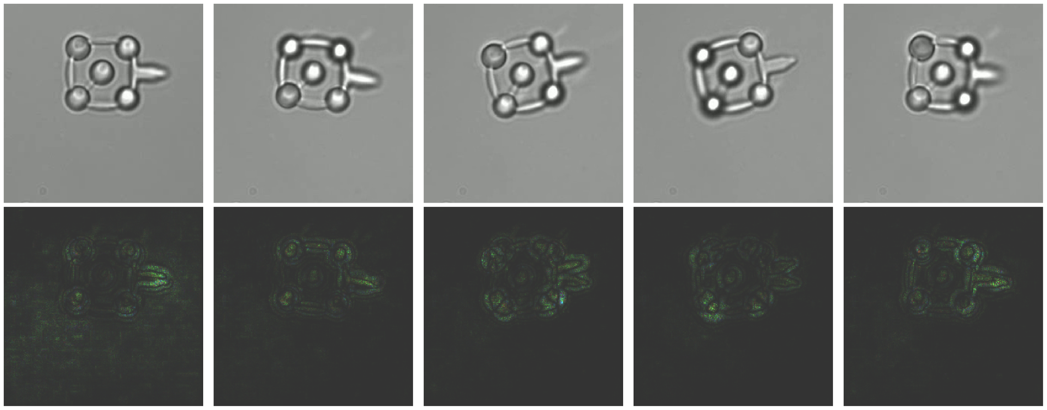
The absence of positive SHAP values around the central TP suggests its limited role in the model’s decision-making process for orientation estimation. This is likely because the central point’s appearance remains relatively constant across different orientations, offering minimal information for the model to discern orientation changes. While Score-CAM relies on class-specific activation maps to highlight salient regions, SHAP provides a more granular and direct quantification of each pixel’s contribution to the estimation. Thus, SHAP values offer an enhanced layer of interpretability, revealing not just the areas of interest but the extent of their influence on the model’s decisions.
In summary, using SHAP values in our orientation angle estimation task offers a transparent window into the model’s reasoning process. By analyzing the SHAP visualizations, we gain confidence in the model’s estimations and an understanding of the features it considers important. This is crucial for deploying machine-learning models in real-world applications where trust and comprehension of model behavior are paramount.
3.6. Comparison of our optical microrobot orientation estimation pipeline with baseline models
An important distinction to note is that our dataset is obtained in-house. Unlike publicly available datasets, which allow for straightforward comparisons, our unique data presents advantages and limitations compared to the state-of-the-art. Most notably, while state-of-the-art models reported higher mean and median errors in orientation estimation than our model, a direct comparison might be misleading due to the distinct nature of the datasets.
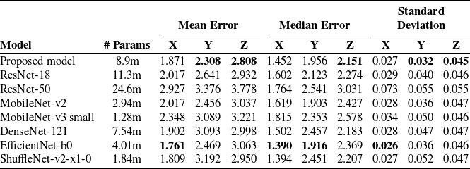
To further investigate our model’s performance, we compared the metrics with some renowned pre-trained models, including ResNet-18, ResNet-50, MobileNet-v2, MobileNet-v3 small, DenseNet-121, EfficientNet-b0 and ShuffleNet-v2-x1-0. These architectures, primarily crafted for image classification tasks, have exhibited state-of-the-art results. It’s pertinent to understand that these models were trained on massive, diverse datasets, making them a challenging benchmark. However, as these networks are tailored for classification, we had to adapt them for our regression problem. We retained only the feature extraction part of these architectures, ensuring compatibility with our task. The architecture of the fully connected layers remained consistent with our original model.
Looking at the results in Table V, our proposed model stands out especially for out-of-plane estimations. For the X-axis, the mean error of 1.871 is close to 1.761, the lowest among all. One reason could be that these models have been designed and trained extensively to extract foundational image features, directly influencing X-axis results. Attaining low error across all three dimensions simultaneously is a challenging task. Table V helps to discern each model’s suitability for specific orientations and offers insights into their relative strengths and weaknesses. The proposed model consistently demonstrated lower mean and median errors in predicting out-of-plane rotations, underlining its precision and robustness. Our model’s efficiency is salient compared to baseline models, considering that these pre-trained models have been trained on extensive and diverse datasets.
Comparison between the proposed model and pre-trained models of metrics for an orientation around X, Y, and Z.
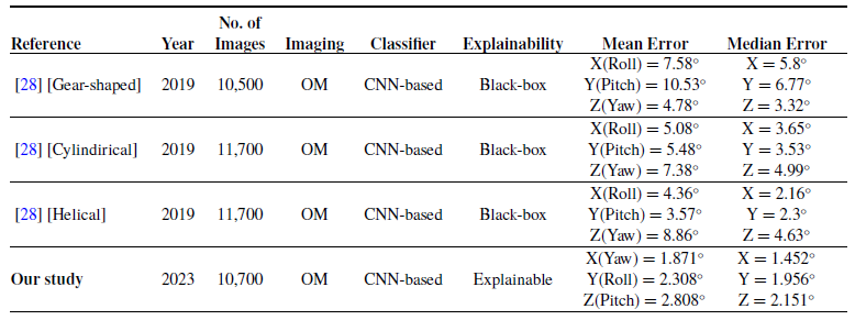
While it is not feasible to directly compare our method for orientation angle estimation to existing state-of-the-art techniques, we have evaluated its performance by benchmarking it against similar work published in 2019 [Reference Grammatikopoulou and Yang28]. The comparative results are presented in Table VI, thus contextualizing our method within the broader research landscape in this domain. As demonstrated in Table VI, our proposed model exhibited a reduced Mean and Median error compared to the existing method. However, it is important to note that the coverage of orientation angles for each axis in [Reference Grammatikopoulou and Yang28] varies from our study. Our model has been used to its maximum potential, constrained only by the limitations of our optical microrobot in collecting ground truth data. Specifically, our model covers an orientation angle of $240^\circ$
for the X-axis, while for the Y and Z axes, we reached an angle of
$240^\circ$
for the X-axis, while for the Y and Z axes, we reached an angle of $70^\circ$
, which are all in clockwise and anti-clockwise directions. The explicit coverage of orientation angles in the compared study is not provided. It is essential to underscore that the error level is influenced by factors such as the number of images used for each axis, the microrobot’s design, and the angle coverage. Within the confines of our study, our model has exhibited a satisfactory level of accuracy, surpassing the accuracy of pre-trained models and delivering highly competitive results compared to similar study in the literature, while providing explainability to the proposed model where state-of-the-art study lacks.
$70^\circ$
, which are all in clockwise and anti-clockwise directions. The explicit coverage of orientation angles in the compared study is not provided. It is essential to underscore that the error level is influenced by factors such as the number of images used for each axis, the microrobot’s design, and the angle coverage. Within the confines of our study, our model has exhibited a satisfactory level of accuracy, surpassing the accuracy of pre-trained models and delivering highly competitive results compared to similar study in the literature, while providing explainability to the proposed model where state-of-the-art study lacks.
Comparison of our work with state-of-the-art for orientation angle estimation (OM = optical microscope).
4. Limitations
This study presents several limitations that should be acknowledged to guide future research in the field of microrobotics. Firstly, the range of microrobot orientations tested was limited, with in-plane rotations set between −120 degrees and +120 degrees, and out-of-plane rotations constrained between −40 degrees and +40 degrees. These constraints were due to 3-D actuation characteristics of our setup, potentially affecting the generalizability of our model to orientations outside the tested range. Secondly, our evaluation relied on an in-house dataset collected using the same imaging system. While this dataset allowed us to assess our model’s performance, it may not fully represent the diversity of conditions encountered in different setups, limiting the generalizability of our findings. Additionally, the lack of publicly available datasets in the microrobotics domain further constrains the ability to benchmark our results against other studies. Finally, while our model demonstrates strong performance within the specific conditions tested, the broader applicability and robustness across diverse scenarios remain areas for future exploration. These limitations highlight the need for further research to expand the orientation range, develop more diverse datasets, and explore additional applications of our approach.
5. Conclusion
This study presents a deep learning-based framework for detecting, tracking, and estimating the orientation of microrobots and TPs under an optical microscope. By integrating and fine-tuning YOLOv7 and DeepSORT algorithms, we achieved improvements in detection accuracy, which are promising for specific microrobotic applications. Our orientation estimation model demonstrated competitive performance when compared to existing architectures like ResNet and MobileNet, particularly in the Y and Z axes. However, the results should be interpreted with caution due to the limitations of our dataset and the specific orientation ranges tested. While our model shows potential for enhancing automation in microrobotic systems, further research is needed to explore its generalizability and applicability across different conditions and setups. This work contributes to the ongoing development of more precise and efficient microrobotic applications, with future efforts required to address the identified limitations and expand the model’s capabilities.
Author contributions
Conceptualization: SC and FS; Methodology: SC, FS, EG, and SH; Validation: SC, FS, and EG; Investigation: FS and SC; Writing – Original Draft: SC and FS; Writing – Review & Editing: SC, FS, EG, and SH; Supervision: FS and SH. Funding acquisition: SH. All authors have read and approved the final version of the manuscript.
Financial support
This work was funded through French National Research Agency Grants OPTOBOTS (ANR-21-CE33-0003).
Conflicts of interest
The authors declare no conflicts of interest exist.
Ethical approval
Not applicable.


 Open access