


1. Introduction
Neurological disorders and injuries significantly impact upper limb function, affecting quality of life and independence. Stroke represents a major global health challenge, with approximately 12.2 million new cases occurring annually worldwide [Reference Feigin, Brainin, Norrving, Martins, Sacco, Hacke, Fisher, Pandian and Lindsay1]. In Europe alone, approximately 1.1 million strokes occur each year, with nearly 10 million people living with stroke-related disability [Reference Wafa, Wolfe, Emmett, Roth, Johnson and Wang2]. Among stroke survivors, 77–85% experience persistent upper limb dysfunction that significantly limits activities of daily living [Reference Weber, Stein and Harvey3, Reference MacDermid, Ramos, Drosdowech, Faber and Patterson4]. Spinal cord injuries contribute an additional 17,000 new cases yearly in the United States alone [Reference Ramos and Morrey5], while age-related musculoskeletal conditions create further rehabilitation demands across aging populations worldwide. Traditional rehabilitation approaches face significant limitations in providing intensive, task-specific training required for optimal motor recovery [Reference Gassert and Dietz6].
Robot-assisted therapy has emerged as a promising intervention [Reference Bertani, Melegari, De Cola, Bramanti, Bramanti and Calabro7, Reference Laut, Porfiri and Raghavan8], yet most devices remain large, stationary, and clinically confined [Reference Rehmat, Zuo, Meng, Liu, Xie and Liang9]. Recent biomechanical research reveals critical limitations in single-joint robotic assistance. Isolated joint assistance creates compensatory muscle activation patterns in adjacent joints within kinematically coupled musculature [Reference Murray, Buchanan and Delp10], reflecting how shoulder-elbow coupling during functional movements requires coordinated assistance approaches [Reference Zhang, Liu, Chen and Xiong11]. Single-joint assistance can lead to overuse injuries and maladaptive motor patterns [Reference Hidler and Wall12, Reference Schweighofer, Xiao, Banala, Agrawal and Krakauer13], highlighting the need for coordinated multi-joint systems.
Cable-driven exoskeletons offer advantages through lightweight, compliant characteristics, and biomimetic force transmission [Reference Georgarakis, Xiloyannis, Wolf and Riener14–Reference Kawamura, Kino and Won16]. However, multi-joint coordination introduces engineering challenges including complex cable routing, soft interface dynamics, and distributed force transmission [Reference Xiloyannis, Alicea, Georgarakis, Haufe, Wolf, Masia and Riener17, Reference Dežman, Asfour and Ude18]. While advances address friction compensation and tension management [Reference Fan, Yuan, Wu and Qiao19, Reference Chen, Casas and Lum20], a fundamental challenge remains: maintaining precise force control across multiple degrees of freedom with compliant, geometrically variable interfaces.
Coordinating shoulder-elbow assistance proves particularly difficult. Most cable-driven exoskeletons rely on force sensors at cable anchor points, where readings are highly sensitive to joint posture and cable routing. This posture-dependent variability compromises force estimation accuracy, directly reducing control precision during functional tasks [Reference Samper-Escudero, Gimenez-Fernandez, Sanchez-Uran and Ferre21]. In single-joint configurations, such constraints are manageable because cable routing can be optimized for one degree of freedom. However, in multi-joint configurations, simultaneously positioning sensors on adjacent body segments (upper arm and forearm) creates mutual spatial interference during coordinated movements: as the shoulder elevates and the elbow flexes simultaneously, the distributed anchor points and their sensors physically limit the achievable range of motion. This is the fundamental spatial constraint motivating the motor-proximal architecture.
Existing cable-driven systems demonstrate effective single-joint assistance. FALCO achieves 2-Degree of Freedom (DOF) shoulder support (flexion/extension and abduction/adduction) through anchor-point force sensing [Reference Missiroli, Ciaramella, Radaelli, Rambaldi, Frisoli, Casadio and Masia22], while Lotti et al. provide 1-DOF elbow assistance using force-based control [Reference Lotti, Xiloyannis, Missiroli, Bokranz, Chiaradia, Frisoli, Riener and Masia23]. However, portable cable-driven exosuits remain limited to single-joint assistance, with no existing system addressing coordinated 3-DOF shoulder-elbow movements within lightweight wearable configurations. It should be noted that the shoulder joint is biomechanically a 3-DOF spherical joint; the proposed system actuates 2 of these DOF (flexion/extension and abduction/adduction), leaving internal/external rotation unassisted. This design choice is justified by Activities of Daily Living (ADL) analysis showing that reaching, feeding, and manipulation tasks primarily require elevation plane control, while internal/external rotation serves secondary repositioning functions. The implications of this simplification are discussed in Section 6.
This work addresses these limitations through a coordinated shoulder-elbow cable-driven exosuit employing motor-proximal sensing architecture. Load cell repositioning from anchor points to positions adjacent to actuation motors eliminates spatial constraints at distributed attachment sites. Combined with geometric compensation algorithms accounting for cable routing geometry and joint configuration, this architecture enables coordinated 3-DOF assistance with preserved 0– $90^\circ$
kinematic range-of-motion (ROM). The key distinction is that workspace preservation is kinematic: the system achieves the target range of motion, but sensing accuracy degrades at elevated angles, a trade-off discussed in detail in Sections 3 and 5.
$90^\circ$
kinematic range-of-motion (ROM). The key distinction is that workspace preservation is kinematic: the system achieves the target range of motion, but sensing accuracy degrades at elevated angles, a trade-off discussed in detail in Sections 3 and 5.
Development followed systematic methodology integrating product design specifications (PDS), multi-criteria decision-making (MCDM), and component dimensioning [Reference Perrelli, Lago, Garofalo, Bruno, Mundo and Carbone24]. The motor-proximal sensing configuration with geometric compensation addresses the ROM–accuracy trade-off inherent to anchor-point architectures (Section 3). Physical prototype development translates design into functional hardware (Section 4). Experimental validation establishes sensing accuracy characteristics and functional effectiveness through human subject trials (n = 5), demonstrating muscle activation reduction while preserving natural coordination patterns (Section 5).
2. Systematic design methodology
Development of the coordinated exosuit followed a structured methodology integrating clinical requirements, biomechanical constraints, and technical feasibility. The framework combines product design specification (PDS) for requirements definition, MCDM for concept selection, and systematic component dimensioning through worst-case biomechanical analysis [Reference Perrelli, Lago, Garofalo, Bruno, Mundo and Carbone24]. Figure 1 presents the systematic approach with iterative refinement loops, providing traceable requirements-to-design mapping that enables transparent justification for technical decisions while reducing prototyping cycles.
2.1. Requirements definition and concept selection
PDS establish quantitative targets derived from clinical needs and biomechanical analysis. Table I summarizes key specifications organized into functional, performance, dimensional, and system categories.
Product design specifications for coordinated shoulder-elbow cable-driven exosuit.

Table I. Long description
The table presents the design specifications for a coordinated shoulder-elbow cable-driven exosuit, organized into four main categories: Functional, Performance, Dimensional, and System. It has four rows and three columns. The columns are labeled Category, Parameter, and Specification. Row 1: Category, Functional; Parameter, Target joints; Specification, Shoulder (2 DOF: flex/ext, abd/add); Elbow (1 DOF: flex/ext). Row 2: Category, Functional; Parameter, Assistance type; Specification, Admittance control with biomechanical modeling. Row 3: Category, Performance; Parameter, Range of motion; Specification, 0-90 degrees all DOF (preserve functional ROM). Row 4: Category, Performance; Parameter, Torque; Specification, Shoulder: 4-6 Nm; Elbow: 3-5 Nm. Row 5: Category, Performance; Parameter, Workspace coverage; Specification, 95 percent functional ADL volume. Row 6: Category, Dimensional; Parameter, Total mass; Specification, less than or equal to 5 kg (battery, actuators, structure). Row 7: Category, Dimensional; Parameter, Form factor; Specification, Wearable, portable, clothing-compatible. Row 8: Category, System; Parameter, Actuation; Specification, Cable-driven, centralized motor unit. Row 9: Category, System; Parameter, Sensing; Specification, Force sensors, IMU (100 Hz). Row 10: Category, System; Parameter, Portability; Specification, Battery-powered, 2 h operation.
The torque specifications (shoulder 4–6 Nm, elbow 3–5 Nm) represent the target assistive torque range at the joint anchor points, derived from ADL biomechanical requirements for the 5th–95th percentile population. These differ from the worst-case gravitational torques computed in Section 2.2 (7.8 Nm shoulder, 2.6 Nm elbow), which represent maximum loading at $90^\circ$
elevation with full arm weight. The PDS torque targets correspond to the desired assistive fraction (gravity compensation assistance level) rather than the total gravitational load, consistent with the admittance control strategy that provides partial unloading proportional to user effort.
$90^\circ$
elevation with full arm weight. The PDS torque targets correspond to the desired assistive fraction (gravity compensation assistance level) rather than the total gravitational load, consistent with the admittance control strategy that provides partial unloading proportional to user effort.
Systematic design methodology framework.

The 3-DOF requirement (2-DOF shoulder + 1-DOF elbow) responds to biomechanical evidence that 85–90% of ADL tasks require coordinated shoulder-elbow movements [Reference Murray, Buchanan and Delp10], while single-joint assistance creates compensatory muscle activation in adjacent joints. The portability constraint ( $\lt$
5 kg) addresses clinical adoption barriers where stationary devices remain confined to institutional settings. Range of motion specifications (0–
$\lt$
5 kg) addresses clinical adoption barriers where stationary devices remain confined to institutional settings. Range of motion specifications (0– $90^\circ$
all DOF) derive from functional workspace analysis, where reaching, feeding, and manipulation tasks concentrate within this operational envelope.
$90^\circ$
all DOF) derive from functional workspace analysis, where reaching, feeding, and manipulation tasks concentrate within this operational envelope.
State-of-art analysis identified representative portable cable-driven systems demonstrating effective single-joint assistance: the FALCO system provides 2-DOF shoulder assistance (flexion/extension, abduction/adduction) through anchor-point force sensing [Reference Missiroli, Ciaramella, Radaelli, Rambaldi, Frisoli, Casadio and Masia22], while the elbow-focused device by Lotti et al. achieves 1-DOF elbow support using force-based control [Reference Lotti, Xiloyannis, Missiroli, Bokranz, Chiaradia, Frisoli, Riener and Masia23]. Both systems exemplify portable cable-driven actuation with demonstrated clinical efficacy for isolated joint movements. However, critical analysis reveals fundamental limitation: neither system supports coordinated shoulder–elbow motion essential for functional ADL execution. Anchor-point force sensing strategies, while effective for single-joint configurations, impose spatial constraints during simultaneous multi-joint movements due to sensor positioning requirements at distributed cable attachment points on adjacent body segments, fundamentally limiting achievable workspace in portable multi-joint configurations.
This identified gap motivated exploration of alternative sensing architectures enabling 3-DOF coordination while preserving cable-driven portability advantages. The proposed motor-proximal sensing configuration addresses this limitation through strategic relocation of force sensors from distributed anchor points to motor-adjacent locations combined with geometric compensation algorithms, preserving force measurement capability while eliminating spatial constraints that restrict coordinated movement workspace.
MCDM evaluation comparing cable-driven alternatives for multi-joint upper limb assistance. Weights ( $W_{C_i}$
) derive from PDS priorities; ratings (
$W_{C_i}$
) derive from PDS priorities; ratings ( $R_{iy}$
) calculated using explicit formulas detailed in text.
$R_{iy}$
) calculated using explicit formulas detailed in text.

Table II. Long description
The table compares three alternatives for cable-driven multi-joint upper limb assistance across twelve criteria. It has three rows labeled as FALCO, Lotti et al., and Proposed device, and thirteen columns labeled as C1 to C12 and Score. Each row contains numerical values representing weights and ratings for each criterion, with the final score calculated for each alternative. Panel A: The first row, FALCO, shows values 1.67, 1, 2, 0.75, 3, 3, 1, 1, 0, 0, 0.67, 2, and a score of 106.7. Panel B: The second row, Lotti et al., shows values 2.94, 1, 2, 0.85, 3, 3, 0, 0, 1, 0, 0.33, 2, and a score of 96.6. Panel C: The third row, Proposed device, shows values 1.43, 1, 2, 0.90, 3, 3, 1, 1, 1, 0, 1.00, 2, and a score of 122.6.
MCDM provided quantitative evaluation of actuation alternatives. The MCDM framework assigns weights $W_{C_i}$
to criteria based on relative importance, derived from PDS priorities. The overall score for alternative
$W_{C_i}$
to criteria based on relative importance, derived from PDS priorities. The overall score for alternative $y$
follows the weighted sum approach with portability constraint:
$y$
follows the weighted sum approach with portability constraint:
 \begin{equation} \mathrm{Score}_y = B_y \times \sum _{i=1}^{12} P_{iy} = B_y \times \sum _{i=1}^{12} (W_{C_i} \times R_{iy}) \end{equation}
where $B_y = R_{2y}$
is the portability boolean (nonportable devices receive zero score),
$B_y = R_{2y}$
is the portability boolean (nonportable devices receive zero score), $W_{C_i}$
is the weight of criterion
$W_{C_i}$
is the weight of criterion $i$
, and
$i$
, and $R_{iy}$
is the performance rating of alternative
$R_{iy}$
is the performance rating of alternative $y$
on criterion
$y$
on criterion $i$
. Table II presents the complete evaluation matrix comparing the two representative single-joint systems against the proposed integrated design. The twelve criteria cover: C1 mass (weight 6), C2 portability (10), C3 self-wearability (5), C4 available torque (4), C5 fixing stability (8), C6 safety (10), C7–C10 DOF coverage boolean indicators for shoulder flex/ext, shoulder abd/add, elbow flex/ext, and wrist (weights 6, 4, 6, 3, respectively), C11 ROM compliance (10), and C12 control complexity (6). Rating calculations follow explicit, reproducible formulas. C1 (Mass):
$i$
. Table II presents the complete evaluation matrix comparing the two representative single-joint systems against the proposed integrated design. The twelve criteria cover: C1 mass (weight 6), C2 portability (10), C3 self-wearability (5), C4 available torque (4), C5 fixing stability (8), C6 safety (10), C7–C10 DOF coverage boolean indicators for shoulder flex/ext, shoulder abd/add, elbow flex/ext, and wrist (weights 6, 4, 6, 3, respectively), C11 ROM compliance (10), and C12 control complexity (6). Rating calculations follow explicit, reproducible formulas. C1 (Mass): $R_{1y} = M_{max}/M_{dy}$
, where
$R_{1y} = M_{max}/M_{dy}$
, where $M_{max}=5.0$
kg (PDS maximum) and
$M_{max}=5.0$
kg (PDS maximum) and $M_{dy}$
is device mass. Applied values: FALCO
$M_{dy}$
is device mass. Applied values: FALCO $M_d=3.0$
kg (shoulder-only configuration)
$M_d=3.0$
kg (shoulder-only configuration) $\to R_1=1.67$
; Lotti et al.
$\to R_1=1.67$
; Lotti et al. $M_d=1.7$
kg (elbow exosuit)
$M_d=1.7$
kg (elbow exosuit) $\to R_1=2.94$
; Proposed
$\to R_1=2.94$
; Proposed $M_d=3.5$
kg (design target)
$M_d=3.5$
kg (design target) $\to R_1=1.43$
. C2 (Portability): Boolean (
$\to R_1=1.43$
. C2 (Portability): Boolean ( $R_2=1$
if battery-powered with no external infrastructure, 0 otherwise). All alternatives achieve
$R_2=1$
if battery-powered with no external infrastructure, 0 otherwise). All alternatives achieve $R_2=1$
. C3 (Self-wearability): Discrete scale (0: requires assistance; 1: difficult but achievable; 2: easily achievable). All cable-driven exosuit architectures achieve
$R_2=1$
. C3 (Self-wearability): Discrete scale (0: requires assistance; 1: difficult but achievable; 2: easily achievable). All cable-driven exosuit architectures achieve $R_3=2$
through adjustable textile interfaces. C4 (Available Torque):
$R_3=2$
through adjustable textile interfaces. C4 (Available Torque): $R_{4y} = \min _{j \in \mathrm{DoF}_y}(T_{available,j}/T_{required,j})$
. Required torques from PDS: shoulder 6 Nm, elbow 5 Nm. FALCO: estimated shoulder capability
$R_{4y} = \min _{j \in \mathrm{DoF}_y}(T_{available,j}/T_{required,j})$
. Required torques from PDS: shoulder 6 Nm, elbow 5 Nm. FALCO: estimated shoulder capability $\approx$
4.5 Nm
$\approx$
4.5 Nm $\to R_4=0.75$
; Lotti et al.: elbow 4.25 Nm average
$\to R_4=0.75$
; Lotti et al.: elbow 4.25 Nm average $\to R_4=0.85$
; Proposed: worst-case elbow 4.5 Nm
$\to R_4=0.85$
; Proposed: worst-case elbow 4.5 Nm $\to R_4=0.90$
. C5 (Stability of Fixing): Discrete scale (1–3). All cable-driven soft architectures employ multi-point textile interfaces achieving
$\to R_4=0.90$
. C5 (Stability of Fixing): Discrete scale (1–3). All cable-driven soft architectures employ multi-point textile interfaces achieving $R_5=3$
. C6 (Safety): Discrete scale (1–3). Cable-driven soft architectures inherently limit injury risk through compliant transmission:
$R_5=3$
. C6 (Safety): Discrete scale (1–3). Cable-driven soft architectures inherently limit injury risk through compliant transmission: $R_6=3$
for all alternatives. C7–C10 (DOF coverage): Boolean indicators for shoulder flex/ext, shoulder abd/add, elbow flex/ext, wrist. FALCO:
$R_6=3$
for all alternatives. C7–C10 (DOF coverage): Boolean indicators for shoulder flex/ext, shoulder abd/add, elbow flex/ext, wrist. FALCO: $R_7=1, R_8=1, R_9=0, R_{10}=0$
; Lotti:
$R_7=1, R_8=1, R_9=0, R_{10}=0$
; Lotti: $R_7=0, R_8=0, R_9=1, R_{10}=0$
; Proposed:
$R_7=0, R_8=0, R_9=1, R_{10}=0$
; Proposed: $R_7=1, R_8=1, R_9=1, R_{10}=0$
. C11 (ROM vs. Functional ROM compliance):
$R_7=1, R_8=1, R_9=1, R_{10}=0$
. C11 (ROM vs. Functional ROM compliance): $R_{11y} = \frac {1}{3}\sum _{l=1}^{3} x_{ly}$
, where
$R_{11y} = \frac {1}{3}\sum _{l=1}^{3} x_{ly}$
, where $x_{ly} = R_{jy} \times (S_{ly}/S_{lf})$
represents DOF-specific workspace compliance (
$x_{ly} = R_{jy} \times (S_{ly}/S_{lf})$
represents DOF-specific workspace compliance ( $S_{lf}=90^\circ$
for all DOF from PDS). FALCO:
$S_{lf}=90^\circ$
for all DOF from PDS). FALCO: $R_{11}=(1\times 1+1\times 1+0)/3=0.67$
; Lotti:
$R_{11}=(1\times 1+1\times 1+0)/3=0.67$
; Lotti: $R_{11}=(0+0+1\times 1)/3=0.33$
; Proposed:
$R_{11}=(0+0+1\times 1)/3=0.33$
; Proposed: $R_{11}=(1+1+1)/3=1.00$
. C12 (Control Complexity): Discrete scale (3: simple direct mapping; 2: moderate force/myoelectric; 1: high complexity adaptive). All evaluated alternatives employ force-based control:
$R_{11}=(1+1+1)/3=1.00$
. C12 (Control Complexity): Discrete scale (3: simple direct mapping; 2: moderate force/myoelectric; 1: high complexity adaptive). All evaluated alternatives employ force-based control: $R_{12}=2$
. The quantitative analysis reveals a systematic gap: FALCO (106.7) and Lotti (96.6) achieve incomplete functional DOF coverage, with scores primarily limited by C9 and C7/C8, respectively. The proposed architecture (122.6) achieves the highest score through complete 3-DOF coverage (C7–C9) and full ROM compliance (C11), at the cost of slightly higher mass. This analysis provided systematic guidance for the design direction, identifying coordinated multi-joint coverage as the primary differentiating criterion.
$R_{12}=2$
. The quantitative analysis reveals a systematic gap: FALCO (106.7) and Lotti (96.6) achieve incomplete functional DOF coverage, with scores primarily limited by C9 and C7/C8, respectively. The proposed architecture (122.6) achieves the highest score through complete 3-DOF coverage (C7–C9) and full ROM compliance (C11), at the cost of slightly higher mass. This analysis provided systematic guidance for the design direction, identifying coordinated multi-joint coverage as the primary differentiating criterion.
2.2. Component dimensioning
Systematic dimensioning establishes component specifications through worst-case biomechanical analysis, ensuring adequate performance across the target population (95th percentile: height H = 1750 mm, body mass M $_{body}$
= 75 kg). Anthropometric scaling follows established relationships [Reference Winter25]: upper arm mass m
$_{body}$
= 75 kg). Anthropometric scaling follows established relationships [Reference Winter25]: upper arm mass m $_{ua}$
= 2.1 kg, forearm mass m
$_{ua}$
= 2.1 kg, forearm mass m $_{fa}$
= 1.2 kg, hand mass m
$_{fa}$
= 1.2 kg, hand mass m $_h$
= 0.45 kg; upper arm length L
$_h$
= 0.45 kg; upper arm length L $_{ua}$
= 325 mm, forearm length L
$_{ua}$
= 325 mm, forearm length L $_{fa}$
= 255 mm.
$_{fa}$
= 255 mm.
Gravitational torque analysis determines actuator requirements. For shoulder assistance accounting for upper arm, forearm, and hand contributions, maximum loading occurs at $90^\circ$
shoulder flexion with elbow extended:
$90^\circ$
shoulder flexion with elbow extended:
 \begin{equation} \tau _{shoulder,gravity}(\theta _{y1}) = \left [m_{ua} \cdot \frac {L_{ua}}{2} + (m_{fa} + m_{hand}) \cdot L_{ua}\right ] \cdot g \cdot \sin (\theta _{y1}) \end{equation}
yielding $\tau _{shoulder,max}$
= 7.8 Nm at
$\tau _{shoulder,max}$
= 7.8 Nm at $90^\circ$
elevation. For elbow assistance accounting for forearm and hand:
$90^\circ$
elevation. For elbow assistance accounting for forearm and hand:
 \begin{equation} \tau _{elbow,gravity}(\theta _{y1}, \theta _{y2}) = \left [m_{fa} \cdot \frac {L_{fa}}{2} + m_{hand} \cdot L_{fa}\right ] \cdot g \cdot \sin (\theta _{y1} + \theta _{y2}) \end{equation}
where $\theta _{y1} + \theta _{y2}$
gives the absolute forearm angle, yielding
$\theta _{y1} + \theta _{y2}$
gives the absolute forearm angle, yielding $\tau _{elbow,max}$
= 2.6 Nm when the forearm is horizontal. Note that these worst-case values reflect the maximum gravitational loading at
$\tau _{elbow,max}$
= 2.6 Nm when the forearm is horizontal. Note that these worst-case values reflect the maximum gravitational loading at $90^\circ$
elevation with fully extended arm, and exceed the PDS torque targets (4–6 Nm shoulder, 3–5 Nm elbow): the PDS specifications define the desired assistive torque fraction for partial gravity compensation, not the total gravitational load.
$90^\circ$
elevation with fully extended arm, and exceed the PDS torque targets (4–6 Nm shoulder, 3–5 Nm elbow): the PDS specifications define the desired assistive torque fraction for partial gravity compensation, not the total gravitational load.
Figure 2 presents gravitational torques across operational range, showing shoulder torque reaching 7.8 Nm at $90^\circ$
flexion and elbow torque reaching 2.6 Nm maximum.
$90^\circ$
flexion and elbow torque reaching 2.6 Nm maximum.
Gravitational torques during $0^\circ$
–
$0^\circ$
– $90^\circ$
operational range for representative user (H=1750 mm, M
$90^\circ$
operational range for representative user (H=1750 mm, M $_{body}$
=75 kg). Shoulder torque (blue) reaches maximum 7.8 Nm at
$_{body}$
=75 kg). Shoulder torque (blue) reaches maximum 7.8 Nm at $90^\circ$
flexion; elbow torque (red) reaches maximum 2.6 Nm when forearm is horizontal.
$90^\circ$
flexion; elbow torque (red) reaches maximum 2.6 Nm when forearm is horizontal.

Cable force requirements incorporate variable moment arm geometry and transmission efficiency. MATLAB kinematic simulation confirms moment arms vary 55–95 mm shoulder (mean 75 mm) and 25–78 mm elbow (mean 51 mm). Accounting for Polytetrafluoroethylene (PTFE) Bowden conduit transmission efficiency ( $\eta _{trans}$
= 0.88):
$\eta _{trans}$
= 0.88):
 \begin{equation} F_{cable,required} = \frac {\tau _{gravity}}{\eta _{trans} \cdot r(\mathbf{q})} \end{equation}
where $r(\mathbf{q})$
denotes the configuration-dependent moment arm. Peak forces occur at approximately
$r(\mathbf{q})$
denotes the configuration-dependent moment arm. Peak forces occur at approximately $73^\circ$
shoulder flexion (118 n) and
$73^\circ$
shoulder flexion (118 n) and $61^\circ$
elbow flexion (58 N), shown in Figure 3.
$61^\circ$
elbow flexion (58 N), shown in Figure 3.
Required cable forces during $0^\circ$
–
$0^\circ$
– $90^\circ$
operational range. Peak forces 118 N (shoulder, blue) and 58 N (elbow, red) occur where ratio
$90^\circ$
operational range. Peak forces 118 N (shoulder, blue) and 58 N (elbow, red) occur where ratio $\tau _{gravity}/r(\mathbf{q})$
is maximum.
$\tau _{gravity}/r(\mathbf{q})$
is maximum.

Motor torque requirements with direct pulley drive (r $_p$
= 20 mm) and safety factor (SF = 1.5) for dynamic loads yield
$_p$
= 20 mm) and safety factor (SF = 1.5) for dynamic loads yield $\tau _{motor,shoulder}$
= 3.5 Nm and
$\tau _{motor,shoulder}$
= 3.5 Nm and $\tau _{motor,elbow}$
= 1.7 Nm required. Selected actuator: AK60-6 quasi-direct drive motor (6 Nm continuous) provides adequate capacity with conservative margins. Force sensors: DYMH 103 S-type load cells (200 N,
$\tau _{motor,elbow}$
= 1.7 Nm required. Selected actuator: AK60-6 quasi-direct drive motor (6 Nm continuous) provides adequate capacity with conservative margins. Force sensors: DYMH 103 S-type load cells (200 N, $\pm$
0.5% FS). Cables: Kevlar braided Ø1.5 mm, breaking load
$\pm$
0.5% FS). Cables: Kevlar braided Ø1.5 mm, breaking load $\gt$
500 N. Bowden: PTFE liner Ø4 mm.
$\gt$
500 N. Bowden: PTFE liner Ø4 mm.
Table III summarizes realized system specifications demonstrating PDS compliance.
System specifications demonstrating PDS compliance.

Table III. Long description
The table has four rows and three columns. The columns are labeled Category, Component/parameter, and Value. Row 1: Category, Mass; Component/parameter, Total system mass; Value, 3.3 kg. Row 2: Category, Actuation; Component/parameter, Motor torque (rated); Value, 6 Nm. Row 3: Category, Actuation; Component/parameter, Cable tension (max shoulder/elbow); Value, 118/58 N. Row 4: Category, Actuation; Component/parameter, Transmission efficiency; Value, 0.88. Row 5: Category, Sensing; Component/parameter, Load cells (3 DYMH 103); Value, 200 N, 0.5% FS. Row 6: Category, Sensing; Component/parameter, IMUs (2 BMI085); Value, 6-axis, 100 Hz. Row 7: Category, Performance; Component/parameter, Operational ROM (all DOF); Value, 0.
Systematic dimensioning achieves 3.3 kg total mass below the 5 kg target while providing specified torque capabilities across full operational workspace. Figure 4 presents complete computer-aided design (CAD) assembly integrating commercial components with custom 3D-printed structures.
Complete CAD assembly: (1) Bowden cable; (2) Kevlar wire; (3) mounting shoulder; (4) cantilever mechanism; (5) shoulder slider guide; (6) shoulder anchor point; (7) elbow anchor point; (8) actuation unit with three motors and control electronics.

3. Motor-proximal sensing architecture
Implementing coordinated shoulder-elbow assistance in cable-driven systems presents fundamental sensing challenges. This section describes the motor-proximal load cell configuration and geometric compensation algorithms designed to manage the ROM–accuracy trade-off, preserving functionally adequate sensing accuracy while maintaining full joint range of motion.
3.1. Sensing architecture and design rationale
Current cable-driven exoskeletons position force sensors at anchor points to measure actual applied forces after transmission losses. This configuration provides direct force measurement advantageous for single-joint systems where cable routing can be optimized for one degree of freedom. However, coordinated multi-joint assistance introduces critical spatial constraints.
During coordinated movements combining shoulder elevation with elbow flexion, sensor positioning at anchor points on adjacent segments (upper arm and forearm) limits range of motion through mutual physical interference. The implemented architecture addresses this limitation through strategic load cell repositioning from anchor points to actuation unit locations. Relocating force sensors from cable anchor points to positions adjacent to the motors enables elbow flexion range of 0– $90^\circ$
while maintaining shoulder elevation range of 0–
$90^\circ$
while maintaining shoulder elevation range of 0– $90^\circ$
, meeting PDS specifications. This configuration eliminates mechanical constraints at distributed anchor points while requiring geometric compensation to translate motor-proximal measurements into effective anchor-point forces.
$90^\circ$
, meeting PDS specifications. This configuration eliminates mechanical constraints at distributed anchor points while requiring geometric compensation to translate motor-proximal measurements into effective anchor-point forces.
Figure 5 illustrates the actuation unit integrating motors, motor-proximal load cells, control electronics, and pulley system within compact posterior-mounted configuration.
Actuation unit with motor-proximal sensing. Internal configuration shows brushless motors (1), dual microcontroller system (2), strategically repositioned load cells (3), and integrated power management (battery 14.8V, 3,700 mAh) (4).

Figure 5. Long description
A diagram of an actuation unit with various labeled components. Panel A: The diagram shows an actuation unit with four main components. The brushless motors are labeled as 1 and there are three of them. The dual microcontroller system is labeled as 2. The strategically repositioned load cells are labeled as 3, with two visible. The integrated power management, which includes a battery of 14.8V and 3,700 mAh, is labeled as 4.
3.2. Geometric compensation
Motor-proximal load cell positioning measures force at motor-side pulleys rather than anchor points, requiring geometric compensation to estimate effective cable tension throughout the workspace. The pulley mounts directly on the load cell body, with cable routing through the pulley and extending through Bowden conduits to anchor points on limb segments. In an ideal cable system with negligible bending stiffness, cable tension remains approximately uniform along its length. The load cell measures the resultant force from both cable segments entering and exiting the pulley. For cable under uniform tension $T$
routing through the pulley:
$T$
routing through the pulley:
 \begin{equation} F_{pulley} = 2T \end{equation}
where the factor of 2 accounts for both cable segments contributing to the measured force. Effective cable tension transmitted to the anchor point, accounting for Bowden conduit transmission losses, is
 \begin{equation} T_{anchor} = \eta _{trans} \cdot \frac {F_{pulley}}{2} \end{equation}
where $\eta _{trans}=0.88$
was established through experimental characterization of the PTFE-lined Bowden conduits in Section 2.2.
$\eta _{trans}=0.88$
was established through experimental characterization of the PTFE-lined Bowden conduits in Section 2.2.
The geometric compensation algorithm translates the estimated anchor tension $T_{anchor}$
into the effective assistive torque at the joint, accounting for the configuration-dependent moment arm. Following the model established in ref. [Reference Missiroli, Ciaramella, Radaelli, Rambaldi, Frisoli, Casadio and Masia22] for shoulder cantilever geometry (Figure 6), the cable length
$T_{anchor}$
into the effective assistive torque at the joint, accounting for the configuration-dependent moment arm. Following the model established in ref. [Reference Missiroli, Ciaramella, Radaelli, Rambaldi, Frisoli, Casadio and Masia22] for shoulder cantilever geometry (Figure 6), the cable length $k(\alpha )$
from the cantilever to the arm anchor as a function of shoulder elevation angle
$k(\alpha )$
from the cantilever to the arm anchor as a function of shoulder elevation angle $\alpha$
is computed via the law of cosines:
$\alpha$
is computed via the law of cosines:
 \begin{equation} k(\alpha ) = \sqrt {k_1^{*2} + k_2^{*2} + 2k_1^* k_2^* \cos (\gamma ^* + \beta ^* + \alpha )} \end{equation}
where $k_1^*$
,
$k_1^*$
, $k_2^*$
are fixed geometric parameters derived from anthropometric measurements (
$k_2^*$
are fixed geometric parameters derived from anthropometric measurements ( $l_b^*$
,
$l_b^*$
, $h_b^*$
,
$h_b^*$
, $l_a^*$
,
$l_a^*$
, $h_a^*$
) and
$h_a^*$
) and $\gamma ^*$
,
$\gamma ^*$
, $\beta ^*$
are fixed angles of the cantilever configuration. The Jacobian relating cable displacement to joint angle gives the effective moment arm:
$\beta ^*$
are fixed angles of the cantilever configuration. The Jacobian relating cable displacement to joint angle gives the effective moment arm:
 \begin{equation} J(\alpha ) = \frac {\partial k}{\partial \alpha } = \frac {-k_1^* k_2^* \sin (\gamma ^* + \beta ^* + \alpha )}{\sqrt {k_1^{*2} + k_2^{*2} + 2k_1^* k_2^* \cos (\gamma ^* + \beta ^* + \alpha )}} \end{equation}
The estimated assistive torque at the shoulder joint is then:
 \begin{equation} \tau _i = J(\alpha ) \cdot T_{anchor} \end{equation}
This torque estimate $\tau _i$
is compared with the reference gravity-compensation torque
$\tau _i$
is compared with the reference gravity-compensation torque $\tau _r$
(Section 3.3) to compute the tracking error for the admittance controller.
$\tau _r$
(Section 3.3) to compute the tracking error for the admittance controller.
The geometric compensation algorithm continuously updates calculations at 100 Hz based on real-time joint configuration from distributed IMU sensors (BMI085, 6-axis). Quaternion-based orientation representation avoids gimbal lock during large-amplitude coordinated movements. IMU fusion integrates accelerometer and gyroscope data to determine shoulder elevation angle $\alpha$
(0–
$\alpha$
(0– $90^\circ$
) and elbow flexion angle
$90^\circ$
) and elbow flexion angle $\theta$
(0–
$\theta$
(0– $90^\circ$
), enabling continuous Jacobian update throughout the operational envelope.
$90^\circ$
), enabling continuous Jacobian update throughout the operational envelope.
Figure 6 illustrates the geometric configuration, including the cantilever mechanism for shoulder assistance and distributed anchor points for elbow support.
Geometric configuration showing shoulder assistance with cantilever mechanism and elbow assistance with cable routing from shoulder anchor to forearm attachment. Motor-proximal load cells measure cable tensions while preserving extended range of motion. Parameters $k_1^*$
,
$k_1^*$
, $k_2^*$
,
$k_2^*$
, $\gamma ^*$
,
$\gamma ^*$
, $\beta ^*$
are the fixed cantilever geometry constants used in the compensation algorithm.
$\beta ^*$
are the fixed cantilever geometry constants used in the compensation algorithm.

3.3. Control system implementation
The control system implements personalized biomechanical modeling using XYZ Euler angle parametrization [Reference Missiroli, Ciaramella, Radaelli, Rambaldi, Frisoli, Casadio and Masia22] to provide coordinated assistance across shoulder and elbow joints. The shoulder joint is modeled as a 2-DOF revolute system within the control framework (elevation $\alpha$
and longitude
$\alpha$
and longitude $\beta$
), consistent with the 2-DOF actuation design. The parametrization follows [Reference Missiroli, Ciaramella, Radaelli, Rambaldi, Frisoli, Casadio and Masia22]:
$\beta$
), consistent with the 2-DOF actuation design. The parametrization follows [Reference Missiroli, Ciaramella, Radaelli, Rambaldi, Frisoli, Casadio and Masia22]:
 \begin{equation} \alpha = \arccos \bigl (c(\phi _2)\,c(\phi _1)\bigr ) \end{equation}
 \begin{equation} \beta = \arctan \!\left (-\frac {s(\phi _2)}{c(\phi _2)\,s(\phi _1)}\right ) \end{equation}
where $\phi _1$
,
$\phi _1$
, $\phi _2$
are the XYZ Euler angles extracted from IMU quaternions,
$\phi _2$
are the XYZ Euler angles extracted from IMU quaternions, $c(\cdot )$
denotes cosine, and
$c(\cdot )$
denotes cosine, and $s(\cdot )$
denotes sine.
$s(\cdot )$
denotes sine.
Under quasi-static conditions (joint velocities and accelerations are low), the gravitational potential energy of the upper limb kinematic chain is
 \begin{equation} U = -g\bigl \{\cos (\alpha )\bigl [K_{ul} + K_l\cos (\theta )\bigr ] - \sin (\alpha )\cos (\beta )\bigl [K_l\sin (\theta )\bigr ]\bigr \} \end{equation}
where $K_{ul} = m_u l_{Gu} + m_l l_u$
and
$K_{ul} = m_u l_{Gu} + m_l l_u$
and $K_l = m_l l_{Gl}$
are anthropometric constants (
$K_l = m_l l_{Gl}$
are anthropometric constants ( $m_u$
,
$m_u$
, $m_l$
: upper arm and forearm+hand masses;
$m_l$
: upper arm and forearm+hand masses; $l_{Gu}$
,
$l_{Gu}$
, $l_{Gl}$
: distances of respective centers of mass from proximal joint),
$l_{Gl}$
: distances of respective centers of mass from proximal joint), $\alpha$
is the shoulder elevation,
$\alpha$
is the shoulder elevation, $\beta$
is the arm longitude, and
$\beta$
is the arm longitude, and $\theta$
is the elbow flexion. This expression follows directly from the z-coordinates of the arm segment centers of mass in the world frame, as derived in ref. [Reference Missiroli, Ciaramella, Radaelli, Rambaldi, Frisoli, Casadio and Masia22].
$\theta$
is the elbow flexion. This expression follows directly from the z-coordinates of the arm segment centers of mass in the world frame, as derived in ref. [Reference Missiroli, Ciaramella, Radaelli, Rambaldi, Frisoli, Casadio and Masia22].
The reference gravity-compensation torque at the shoulder is
 \begin{equation} \tau _r = g\bigl \{\sin (\alpha )\bigl [K_{ul} + K_l\cos (\theta )\bigr ] + \cos (\alpha )\cos (\beta )\bigl [K_l\sin (\theta )\bigr ]\bigr \} + D_1\dot {\alpha } + D_2\dot {\theta } \end{equation}
where $D_1$
and
$D_1$
and $D_2$
are positive damping coefficients added to model biological joint damping and ensure smooth controller behavior [Reference Missiroli, Ciaramella, Radaelli, Rambaldi, Frisoli, Casadio and Masia22]. These coefficients were determined empirically through iterative experimental tuning using the Ziegler–Nichols method as initial estimate, following the same procedure reported in ref. [Reference Missiroli, Ciaramella, Radaelli, Rambaldi, Frisoli, Casadio and Masia22] for the FALCO exosuit. Specifically, the tuning procedure minimized torque tracking error during controlled sinusoidal reference trajectories while maintaining stability across the five participants. The resulting values were consistent across participants (
$D_2$
are positive damping coefficients added to model biological joint damping and ensure smooth controller behavior [Reference Missiroli, Ciaramella, Radaelli, Rambaldi, Frisoli, Casadio and Masia22]. These coefficients were determined empirically through iterative experimental tuning using the Ziegler–Nichols method as initial estimate, following the same procedure reported in ref. [Reference Missiroli, Ciaramella, Radaelli, Rambaldi, Frisoli, Casadio and Masia22] for the FALCO exosuit. Specifically, the tuning procedure minimized torque tracking error during controlled sinusoidal reference trajectories while maintaining stability across the five participants. The resulting values were consistent across participants ( $D_1 = 0.15 \pm 0.03$
Nm
$D_1 = 0.15 \pm 0.03$
Nm $\cdot$
s/rad,
$\cdot$
s/rad, $D_2 = 0.08 \pm 0.02$
Nm
$D_2 = 0.08 \pm 0.02$
Nm $\cdot$
s/rad), confirming robustness of the empirical identification.
$\cdot$
s/rad), confirming robustness of the empirical identification.
The low-level admittance controller converts the torque tracking error $\tau _{error} = \tau _r - \tau _i$
into motor velocity commands. In the Laplace domain [Reference Missiroli, Ciaramella, Radaelli, Rambaldi, Frisoli, Casadio and Masia22, Reference Keemink, van der Kooij and Stienen30]:
$\tau _{error} = \tau _r - \tau _i$
into motor velocity commands. In the Laplace domain [Reference Missiroli, Ciaramella, Radaelli, Rambaldi, Frisoli, Casadio and Masia22, Reference Keemink, van der Kooij and Stienen30]:
 \begin{equation} \frac {\dot{\!x}(s)}{\tau (s)} = R(s) = B_a + \frac {D_a}{s} + M_a s \end{equation}
where $B_a$
,
$B_a$
, $D_a$
, and
$D_a$
, and $M_a$
are the admittance proportional, integral, and derivative gains, respectively, tuned empirically for stable torque tracking.
$M_a$
are the admittance proportional, integral, and derivative gains, respectively, tuned empirically for stable torque tracking.
The system implements two parallel synchronized control loops. Shoulder tensioning control incorporates the high-level gravity compensation model Eq. (13) with the low-level admittance controller Eq. (14), translating torque error into motor speed commands. Shoulder translating control utilizes a secondary motor to reposition the anchor point on the slider, aligning the cable direction with the highest elevation point of the arc (tracking $\beta$
through a PID position controller with adaptive fading filter). Elbow control implements an independent admittance loop with geometric compensation adapted to the elbow cable routing. All three loops share IMU kinematic data.
$\beta$
through a PID position controller with adaptive fading filter). Elbow control implements an independent admittance loop with geometric compensation adapted to the elbow cable routing. All three loops share IMU kinematic data.
Figure 7 presents the CAD representation of the coordinated control architecture.
CAD representation of coordinated control architecture showing three parallel loops: elbow assistance (red), shoulder tensioning (blue, high-level feedforward gravity compensation + low-level admittance feedback), and shoulder translating (blue, PID position control of anchor geometry). Each subsystem operates independently while sharing IMU sensor information.

Figure 7. Long description
A CAD representation of a coordinated control architecture showing three parallel loops: elbow assistance, shoulder tensioning, and shoulder translating. The elbow assistance control is highlighted in red, the shoulder tensioning control is highlighted in blue with high-level feedforward gravity compensation and low-level admittance feedback, and the shoulder translating control is highlighted in blue with PID position control of anchor geometry. Each subsystem operates independently while sharing IMU sensor information.
Figure 8 presents the detailed control flow. The feedforward pathway (gravity compensation model) provides the reference torque $\tau _r$
; the feedback pathway (admittance controller) closes the loop using the interaction torque
$\tau _r$
; the feedback pathway (admittance controller) closes the loop using the interaction torque $\tau _i$
estimated from motor-proximal load cells via the geometric compensation Eqs. (5–9).
$\tau _i$
estimated from motor-proximal load cells via the geometric compensation Eqs. (5–9).
Control flow diagram. The shoulder tensioning loop (magenta) combines feedforward gravity compensation (reference torque $\tau _r$
from biomechanical model, Eq. (13) with feedback admittance control (interaction torque
$\tau _r$
from biomechanical model, Eq. (13) with feedback admittance control (interaction torque $\tau _i$
from motor-proximal load cells via geometric compensation, Eq. (9). The translating loop (green) tracks the longitude angle
$\tau _i$
from motor-proximal load cells via geometric compensation, Eq. (9). The translating loop (green) tracks the longitude angle $\beta$
via PID position control. The elbow loop (orange) implements independent admittance control with geometric compensation of motor-proximal force measurements. All subsystems share joint angle estimates (
$\beta$
via PID position control. The elbow loop (orange) implements independent admittance control with geometric compensation of motor-proximal force measurements. All subsystems share joint angle estimates ( $\alpha$
,
$\alpha$
, $\beta$
,
$\beta$
, $\theta$
) from IMU sensors, where
$\theta$
) from IMU sensors, where $\omega _{ref}$
denotes the motor velocity command for the translating actuator.
$\omega _{ref}$
denotes the motor velocity command for the translating actuator.

IMU sensors positioned on upper arm and forearm provide three-dimensional orientation processed through quaternion representation at 100 Hz via BLE UART protocol [Reference Wang, Zhang, Kong, Su, Yuan and Zhao27].
4. Prototype development
Following design finalization, prototype development translates CAD models into physical hardware validating systematic methodology and motor-proximal sensing architecture. The prototype employs Fused Deposition Modeling 3D printing (PLA, 0.2 mm layers, 40% gyroid infill) for custom mechanical components enabling rapid iteration. Shoulder and elbow bracelets use Boa $^{\circledR }$
dial-actuated closures accommodating 5th–95th percentile anthropometry. High-tensile Kevlar cables (Ø1.0 mm, 150 N breaking) route through PTFE-lined Bowden conduits (Ø5.0 mm OD, 1.6 mm ID) with cables pre-tensioned to 5–8 N ensuring immediate force transmission while avoiding unwanted assistive torques at rest.
$^{\circledR }$
dial-actuated closures accommodating 5th–95th percentile anthropometry. High-tensile Kevlar cables (Ø1.0 mm, 150 N breaking) route through PTFE-lined Bowden conduits (Ø5.0 mm OD, 1.6 mm ID) with cables pre-tensioned to 5–8 N ensuring immediate force transmission while avoiding unwanted assistive torques at rest.
System assembly integrates: actuation unit with motor mounting, motor-proximal load cells, and electronics (Arduino MKR WiFi, HX711 amplifiers, 14.8V LiPo); wearable interfaces with Boa $^{\circledR}$
closures and IMU modules (BMI085); cable system with Bowden routing and Kevlar termination; electrical interconnection via motor CAN bus and IMU BLE UART; software calibration for load cells, IMUs, and motor encoders.
$^{\circledR}$
closures and IMU modules (BMI085); cable system with Bowden routing and Kevlar termination; electrical interconnection via motor CAN bus and IMU BLE UART; software calibration for load cells, IMUs, and motor encoders.
Figure 9 presents complete integrated prototype demonstrating systematic assembly of commercial components with 3D-printed structures.
Complete system assembly: (1) Cantilever mechanism; (2) shoulder bracelet with integrated slider guide and anchor point; (3) Eebow bracelet; (4) actuation unit with three motors, load cells, and control electronics; (5) Bluetooth IMU sensors; (6) emergency stop button

Figure 9. Long description
A person wearing a multi-joint robotic assistance system. Panel A: Front view of the system. Panel B: Back view of the system. The components include (1) Cantilever mechanism, (2) shoulder bracelet with integrated slider guide and anchor point, (3) elbow bracelet, (4) actuation unit with three motors, load cells, and control electronics, (5) Bluetooth IMU sensors, and (6) emergency stop button.
Total system mass 3.3 kg meets portability target $\lt$
5 kg, with actuation unit 2.5 kg (concentrated on posterior torso via harness) and wearable interfaces 0.8 kg (distributed across shoulder/elbow cuffs). Battery runtime exceeds 2 hours continuous operation under nominal load conditions. Average donning/doffing time measured during the experimental sessions was 8
$\lt$
5 kg, with actuation unit 2.5 kg (concentrated on posterior torso via harness) and wearable interfaces 0.8 kg (distributed across shoulder/elbow cuffs). Battery runtime exceeds 2 hours continuous operation under nominal load conditions. Average donning/doffing time measured during the experimental sessions was 8 $\pm$
2 min for initial setup and 4
$\pm$
2 min for initial setup and 4 $\pm$
1 min for subsequent sessions, enabling self-application with bracelet adjustment and cable tension managed through the Boa
$\pm$
1 min for subsequent sessions, enabling self-application with bracelet adjustment and cable tension managed through the Boa $^{\circledR}$
Fit System. Figure 10 demonstrates the wearable system worn during preliminary testing.
$^{\circledR}$
Fit System. Figure 10 demonstrates the wearable system worn during preliminary testing.
Wearable system demonstrating functional prototype worn by user. System mass 3.3 kg meets portability requirement. Posterior-mounted actuation unit distributes mass on torso via ergonomic harness.

5. Experimental validation
The motor-proximal sensing architecture and coordinated assistance system require comprehensive experimental validation establishing technical feasibility and functional effectiveness. This section presents two-phase validation: (1) sensing accuracy assessment addressing force estimation capabilities and (2) human subject trials evaluating functional assistance and physiological outcomes.
5.1. Phase 1: Sensing accuracy assessment
Before proceeding to full system human trials, the motor-proximal sensing approach required experimental validation confirming geometric compensation algorithms maintain adequate control accuracy across extended ROM necessary for functional multi-joint coordination.
Comprehensive validation employed extensive data collection across complete operational workspace (shoulder elevation 0– $90^\circ$
, elbow flexion 0–
$90^\circ$
, elbow flexion 0– $90^\circ$
) during human subject trials. Data were aggregated across all five participants and all experimental conditions, resulting in measurement samples spanning the complete functional range.
$90^\circ$
) during human subject trials. Data were aggregated across all five participants and all experimental conditions, resulting in measurement samples spanning the complete functional range.
Kinematic data were collected at 100 Hz. For each movement configuration, the system recorded: (1) theoretical gravitational torque $\tau _{theory}$
computed from the biomechanical model Eq. (12), (2) motor-proximal measured forces
$\tau _{theory}$
computed from the biomechanical model Eq. (12), (2) motor-proximal measured forces $F_{pulley}$
, and (3) geometrically compensated torque estimates
$F_{pulley}$
, and (3) geometrically compensated torque estimates $\tau _{estimated}$
via Eqs. (6–9), and (4) estimation error
$\tau _{estimated}$
via Eqs. (6–9), and (4) estimation error $\epsilon = \tau _{estimated} - \tau _{theory}$
.
$\epsilon = \tau _{estimated} - \tau _{theory}$
.
Aggregate analysis across the complete workspace revealed R $^2$
= 0.75, RMSE = 1.51 Nm, and near-zero mean error (0.13 Nm) indicating absence of systematic bias. However, workspace-dependent analysis reveals critical spatial variation:
$^2$
= 0.75, RMSE = 1.51 Nm, and near-zero mean error (0.13 Nm) indicating absence of systematic bias. However, workspace-dependent analysis reveals critical spatial variation:
-
• 0– $30^\circ$
elevation: R
$^2$
= 0.66, RMSE = 1.08 Nm – moderate correlation with acceptable error for admittance control.
$30^\circ$
elevation: R
$^2$
= 0.66, RMSE = 1.08 Nm – moderate correlation with acceptable error for admittance control. -
• 30–
$60^\circ$
elevation: R
$^2$
= 0.22, RMSE = 2.26 Nm – degrading correlation reflecting increasing geometric sensitivity. -
• 60–
$90^\circ$
elevation: R
$^2$
= 0.06, RMSE = 3.40 Nm – poor correlation due to near-zero Jacobian
$J(\alpha )$
Eq. (8) at elevated angles, where small changes in cable geometry produce large estimation uncertainty.


This workspace-dependent degradation is a fundamental consequence of the motor-proximal architecture: at high shoulder elevation, the effective moment arm approaches its minimum value, amplifying measurement uncertainty. The 0– $60^\circ$
range encompasses the primary ADL workspace (reaching, feeding, and object manipulation), where sensing accuracy is adequate for functional admittance control. The 60–
$60^\circ$
range encompasses the primary ADL workspace (reaching, feeding, and object manipulation), where sensing accuracy is adequate for functional admittance control. The 60– $90^\circ$
range, relevant for overhead tasks, presents a known limitation requiring future architectural refinement (discussed in Section 6).
$90^\circ$
range, relevant for overhead tasks, presents a known limitation requiring future architectural refinement (discussed in Section 6).
Figure 11 presents overall validation results demonstrating correlation between theoretical and measured torques with unbiased error distribution.
Gravity compensation validation: (a) Correlation between theoretical and measured torques (R $^2$
= 0.75, RMSE=1.51 nm); (b) error distribution showing near-zero bias (mean=0.13 nm, std=1.51 nm).
$^2$
= 0.75, RMSE=1.51 nm); (b) error distribution showing near-zero bias (mean=0.13 nm, std=1.51 nm).

Figure 11. Long description
Panel A: A scatter plot shows the correlation between theoretical gravity torque and estimated torque. The x-axis represents theoretical gravity torque in Newton meters (Nm), and the y-axis represents estimated torque in Newton meters (Nm). The plot includes a red dashed line indicating perfect agreement. The R-squared value is 0.747, and the root mean square error (RMSE) is 1.51 Nm. The data points are scattered around the line, showing a general trend of increasing estimated torque with increasing theoretical gravity torque. Panel B: A histogram displays the error distribution between theoretical and estimated torques. The x-axis represents the error in Newton meters (Nm), and the y-axis represents the frequency. The histogram shows a near-zero bias with a mean error of 0.13 Nm and a standard deviation of 1.51 Nm. The majority of the errors are concentrated around zero, indicating a good agreement between theoretical and estimated torques.
5.2. Phase 2: Human subject trials
5.2.1. Experimental methods
Five healthy male participants (age 29 $\pm$
5 y, height 1.8
$\pm$
5 y, height 1.8 $\pm$
0.1 m, body mass 73
$\pm$
0.1 m, body mass 73 $\pm$
9 kg) were recruited through convenience sampling. The homogeneous demographic profile was intentionally selected to minimize anthropometric confounding variables in this proof-of-concept study. The limitation of this choice for generalizability is acknowledged in Section 6.
$\pm$
9 kg) were recruited through convenience sampling. The homogeneous demographic profile was intentionally selected to minimize anthropometric confounding variables in this proof-of-concept study. The limitation of this choice for generalizability is acknowledged in Section 6.
Participants met selection requirements: (1) anthropometric measurements compatible with exosuit parameters (height 1.65–1.95 m, body mass 60–90 kg), (2) normal joint ROM across all upper limb articulations, (3) sufficient muscle strength to complete testing protocol without assistance, and (4) absence of neurological, musculoskeletal, or cardiovascular conditions.
All experimental procedures were conducted in accordance with the Declaration of Helsinki. Written informed consent was obtained from all participants. Equipment contacting participants was thoroughly disinfected between users using standard sterilization protocols.
Experimental protocol employed within-subjects repeated-measures design. Participants completed all tasks under two randomized conditions: Exo On (full exosuit assistance with active gravity compensation) and No Exo (sensor-only configuration with IMUs worn, no mechanical assistance).
Controlled ROM tasks consisted of three primary movements performed at $90^\circ$
amplitude with 5 repetitions
$90^\circ$
amplitude with 5 repetitions $\times$
3 series each (Figure 12): (a) elbow flexion–extension, (b) shoulder flexion–extension, and (c) shoulder abduction-adduction. Reference trajectories were sinusoidal profiles at approximately 0.2 Hz. Functional tasks included a standardized drinking sequence (Figure 13).
$\times$
3 series each (Figure 12): (a) elbow flexion–extension, (b) shoulder flexion–extension, and (c) shoulder abduction-adduction. Reference trajectories were sinusoidal profiles at approximately 0.2 Hz. Functional tasks included a standardized drinking sequence (Figure 13).
Controlled range of motion tasks performed at standardized $90^\circ$
amplitude with fixed repetition structure enabling systematic comparison across assistance conditions.
$90^\circ$
amplitude with fixed repetition structure enabling systematic comparison across assistance conditions.

Functional drinking task demonstrating complex multi-joint coordination: (a) initial reach, (b) precision grasping, (c) coordinated lifting and drinking motion, (d) controlled return to rest position.

Each participant completed a single 2-hour session: (1) 10-min familiarization, (2) baseline measurements (maximal voluntary contraction (MVC) collection for electromyography (EMG) normalization, anthropometric calibration), (3) randomized task execution with 5-min rest periods between conditions, and (4) subjective feedback collection. Figure 14 illustrates the complete data acquisition infrastructure deployed during experimental trials.
Data acquisition setup with dual-pathway architecture: kinematic processing station and wireless EMG system, both providing real-time signal visualization during trials.

5.2.2. Functional outcomes
Surface EMG data were acquired using a wireless Delsys system targeting three key muscles: biceps brachii (elbow flexion), anterior deltoid (shoulder flexion), and medial deltoid (shoulder abduction). Electrode placement followed SENIAM guidelines (Figure 15).
EMG electrode placement following SENIAM guidelines: (a) biceps brachii and anterior deltoid positioning; (b) medial deltoid placement optimized to avoid interference with cable routing during multi-joint movements.

EMG preprocessing: bandpass filtering (15–450 Hz, 4th-order Butterworth), full-wave rectification, low-pass filtering (6 Hz cutoff), normalization to individual MVC values collected at the start of each session following standardized isometric contraction protocols. Root mean square (RMS) values were computed over complete movement cycles. The reported RMS values are expressed as fractions of MVC (dimensionless, where 1.0 = 100% MVC). Values above 1.0 observed in some muscles reflect the higher activation demands of the multi-joint coordinated tasks relative to the isolated MVC reference contractions, which were collected for each muscle individually at a fixed posture and may not capture peak activation across all task postures. Kinematics: Joint angles derived from IMU quaternions recorded at 100 Hz.
Statistical Analysis: Paired $t$
-tests compared conditions. With three muscles tested, Bonferroni-corrected significance threshold is
$t$
-tests compared conditions. With three muscles tested, Bonferroni-corrected significance threshold is $\alpha _{corr} = 0.05/3 = 0.017$
. Effect sizes reported as Cohen’s
$\alpha _{corr} = 0.05/3 = 0.017$
. Effect sizes reported as Cohen’s $d$
(small: 0.2, medium: 0.5, large: 0.8). Degrees of freedom df = 4 (n
$d$
(small: 0.2, medium: 0.5, large: 0.8). Degrees of freedom df = 4 (n $-$
1).
$-$
1).
Table IV presents aggregate EMG analysis across all experimental tasks.
Aggregate muscle activation analysis. RMS values represent normalized activation (fraction of MVC) averaged across tasks. Bonferroni-corrected significance threshold $\alpha _{corr}=0.017$
(3 comparisons).
$\alpha _{corr}=0.017$
(3 comparisons). $\dagger$
denotes significance after Bonferroni correction.
$\dagger$
denotes significance after Bonferroni correction.

Table IV. Long description
The table presents data on muscle activation with and without an exoskeleton. It has five rows and six columns. The columns are labeled Muscle, No exo (RMS±SD), Exo on (RMS±SD), Reduction (percent), p-value, and Cohen’s d. The rows are labeled Biceps Brachii, Anterior Deltoid, Medial Deltoid, and Average. Row 1: Biceps Brachii, No exo 1.294±0.265, Exo on 1.059±0.162, Reduction 18.2 percent, p-value 0.031, Cohen’s d 0.9. Row 2: Anterior Deltoid, No exo 1.802±0.335, Exo on 1.636±0.285, Reduction 9.2 percent, p-value 0.089, Cohen’s d 0.6. Row 3: Medial Deltoid, No exo 2.037±0.321, Exo on 1.473±0.249, Reduction 27.7 percent, p-value 0.012, Cohen’s d 1.2. Row 4: Average, No exo, Exo on, Reduction 18.4 percent ± 9.3. The table shows the reduction in muscle activation when using an exoskeleton, with notable reductions in the Medial Deltoid and Biceps Brachii muscles.
After Bonferroni correction ( $\alpha _{corr}=0.017$
), medial deltoid reduction (27.7%, p = 0.012, d = 1.2) reaches statistical significance, representing a large effect consistent with effective shoulder abduction assistance. Biceps brachii reduction (18.2%, p = 0.031, d = 0.9) shows a large effect size but does not survive Bonferroni correction, and should be interpreted as exploratory. Anterior deltoid (9.2%, p = 0.089, d = 0.6) approaches a medium effect but is non-significant. The 18.4% average reduction across muscles is reported as indicative of clinically meaningful assistance: reductions of this magnitude are consistent with thresholds associated with measurable fatigue reduction in endurance-based rehabilitation protocols reported in the cable-driven exosuit literature [Reference Missiroli, Ciaramella, Radaelli, Rambaldi, Frisoli, Casadio and Masia22, Reference Lotti, Xiloyannis, Missiroli, Bokranz, Chiaradia, Frisoli, Riener and Masia23], although direct clinical significance thresholds vary by application and patient population.
$\alpha _{corr}=0.017$
), medial deltoid reduction (27.7%, p = 0.012, d = 1.2) reaches statistical significance, representing a large effect consistent with effective shoulder abduction assistance. Biceps brachii reduction (18.2%, p = 0.031, d = 0.9) shows a large effect size but does not survive Bonferroni correction, and should be interpreted as exploratory. Anterior deltoid (9.2%, p = 0.089, d = 0.6) approaches a medium effect but is non-significant. The 18.4% average reduction across muscles is reported as indicative of clinically meaningful assistance: reductions of this magnitude are consistent with thresholds associated with measurable fatigue reduction in endurance-based rehabilitation protocols reported in the cable-driven exosuit literature [Reference Missiroli, Ciaramella, Radaelli, Rambaldi, Frisoli, Casadio and Masia22, Reference Lotti, Xiloyannis, Missiroli, Bokranz, Chiaradia, Frisoli, Riener and Masia23], although direct clinical significance thresholds vary by application and patient population.
Figure 16 presents representative electromyographic activation patterns during the pick-and-place task.
Electromyographic analysis during pick-and-place task: (a) temporal EMG activity showing activation patterns throughout movement cycles; (b) RMS values normalized to MVC comparing no exo (blue) and exo on (green) conditions.

Figure 16. Long description
The image contains two sets of graphs. Panel A shows three line graphs depicting temporal EMG activity for the medial deltoid, anterior deltoid, and biceps muscles. The x-axis represents time in seconds, and the y-axis represents EMG activity as a percentage of maximum voluntary contraction (percent MVC). The green lines indicate the exoskeleton on condition, while the blue lines indicate the no exoskeleton condition. Panel B shows three bar graphs comparing the root mean square (RMS) values normalized to MVC for the same muscles. The x-axis is labeled RMS, and the y-axis represents the RMS values. The green bars represent the exoskeleton on condition, and the blue bars represent the no exoskeleton condition. The graphs illustrate differences in muscle activation patterns and RMS values between the two conditions.
Movement quality assessment demonstrated preserved joint coordination during assisted conditions. Trajectory tracking: elbow flexion–extension R $^2$
= 0.82
$^2$
= 0.82 $\pm$
0.071, shoulder flexion–extension R
$\pm$
0.071, shoulder flexion–extension R $^2$
= 0.64
$^2$
= 0.64 $\pm$
0.14, shoulder abduction-adduction R
$\pm$
0.14, shoulder abduction-adduction R $^2$
= 0.65
$^2$
= 0.65 $\pm$
0.15.
$\pm$
0.15.
The functional drinking task provided comprehensive evaluation of naturalistic movement patterns. Figure 17 shows representative kinematic profiles, demonstrating preserved coordination across multiple cycles. The temporal offset in EMG and kinematic peak timing between Exo On and No Exo conditions (most visible in Figure 18) reflects the dynamic response of the admittance controller: the exosuit assistance introduces a compliance-like behavior that slightly shifts the timing of peak muscle recruitment and joint angles relative to the unassisted condition. This effect is intrinsic to admittance control and has been reported in comparable cable-driven systems [Reference Missiroli, Ciaramella, Radaelli, Rambaldi, Frisoli, Casadio and Masia22, Reference Keemink, van der Kooij and Stienen30]. The angular differences between conditions in shoulder kinematics during the drinking task arise primarily from the altered torque balance at the shoulder joint: with active gravity compensation, the effective gravitational load perceived by the muscles is reduced, leading to modified trajectory profiles as the neuromuscular system adapts to the assistive input.
Movement precision via RMSE: elbow $13.04 \pm 1.31^\circ$
, shoulder flexion
$13.04 \pm 1.31^\circ$
, shoulder flexion $16.36 \pm 4.16^\circ$
, shoulder abduction 13.37
$16.36 \pm 4.16^\circ$
, shoulder abduction 13.37 $\pm 3.32^\circ$
.
$\pm 3.32^\circ$
.
Range of motion analysis revealed minimal kinematic constraints. Shoulder flexion: 87.2 $\pm 3.4^\circ$
(Exo On) vs. 89.8
$\pm 3.4^\circ$
(Exo On) vs. 89.8 $\pm \,2.9^\circ$
(No Exo), 2.9% reduction. Shoulder abduction: 85.9
$\pm \,2.9^\circ$
(No Exo), 2.9% reduction. Shoulder abduction: 85.9 $\pm 3.8^\circ$
vs. 88.7
$\pm 3.8^\circ$
vs. 88.7 $\pm 3.2^\circ$
, 3.2% reduction. Elbow flexion: 88.9
$\pm 3.2^\circ$
, 3.2% reduction. Elbow flexion: 88.9 $\pm 2.7^\circ$
vs. 90.1
$\pm 2.7^\circ$
vs. 90.1 $\pm 2.4^\circ$
, minimal constraint. All DOF achieved
$\pm 2.4^\circ$
, minimal constraint. All DOF achieved $\gt 85^\circ$
ROM under assisted conditions.
$\gt 85^\circ$
ROM under assisted conditions.
5.3. Comparative positioning
Table V presents systematic comparison establishing the system’s position within the technological landscape. Heterogeneous metrics, different participant populations, and different task protocols preclude direct performance ranking; comparison focuses on capability positioning.
Representative upper limb cable-driven assistance systems. Heterogeneous metrics, tasks, and participant populations preclude direct performance comparison.

Table V. Long description
A table comparing upper limb cable-driven assistance systems. The table has five rows and five columns. Column headers are System, DOF assisted, Mass (kg), Sensing, and Primary outcome. Row 1: FALCO, 2 (shoulder), 3.0, Anchor point, 31% avg. activation reduction. Row 2: Lotti et al., 1 (elbow), 1.7, Anchor point, 35% fatigue reduction. Row 3: Kim et al., 2 (rigid), 7.5, Force, 26% overhead task. Row 4: Proposed system, 3 (coord.), 3.3, Motor-prox., 18% multi-joint avg. $^\dagger$
Across coordinated shoulder-elbow tasks; only medial deltoid reduction survives Bonferroni correction.
$^\dagger$
Across coordinated shoulder-elbow tasks; only medial deltoid reduction survives Bonferroni correction.
Kinematic tracking performance during standardized movement tasks for representative participant. Green: Exo On condition, blue: No Exo condition, red dashed: sinusoidal reference trajectory ( $90^\circ$
amplitude). Similar tracking patterns observed across all participants.
$90^\circ$
amplitude). Similar tracking patterns observed across all participants.

Figure 17. Long description
Three line graphs depict elbow flexion-extension, shoulder flexion-extension, and shoulder abduction-adduction angles over time. Panel A: The line graph shows elbow flexion-extension angles in degrees over time in seconds. The green line represents the Exo On condition, the blue line represents the No Exo condition, and the red dashed line represents the sinusoidal reference trajectory. Panel B: The line graph shows shoulder flexion-extension angles in degrees over time in seconds. The green line represents the Exo On condition, the blue line represents the No Exo condition, and the red dashed line represents the sinusoidal reference trajectory. Panel C: The line graph shows shoulder abduction-adduction angles in degrees over time in seconds. The green line represents the Exo On condition, the blue line represents the No Exo condition, and the red dashed line represents the sinusoidal reference trajectory.
Kinematic analysis during functional drinking task showing coordinated shoulder and elbow joint angles. Green: Exo On, blue: No Exo. Preserved coordination across movement cycles demonstrates system maintains natural multi-joint coordination patterns during complex functional activities.

The proposed system achieves multi-joint coordination unavailable in prior portable systems. Lower muscle activation reduction relative to FALCO and Lotti reflects task complexity rather than inferior performance: single-joint systems concentrate all actuation on one DOF, while coordinated assistance distributes torque across three DOF simultaneously. Direct performance comparison is further complicated by different experimental tasks and participant populations.
6. Discussion
6.1. Design methodology and architectural innovation
The systematic framework – integrating PDS, MCDM, and biomechanical dimensioning – constitutes a methodological contribution beyond a mere procedural description. In the specific context of multi-joint wearable rehabilitation devices, where competing requirements (portability, ROM, force accuracy, DOF coverage) create nontrivial design trade-offs, an explicit and traceable decision framework directly shapes the resulting architecture. In the present case, the MCDM evaluation identified DOF coverage and ROM compliance as the dominant discriminating criteria, providing quantitative justification for the motor-proximal sensing architecture over anchor-point alternatives that would not have emerged from qualitative comparison alone. This traceability is particularly relevant for rehabilitation devices intended for clinical adoption, where design rationale must be documented and reproducible [Reference Perrelli, Lago, Garofalo, Bruno, Mundo and Carbone24]. Quantitative concept evaluation through MCDM provided transparent justification of the motor-proximal architecture as the approach maximizing functional DOF coverage within the portability constraint. Component dimensioning through worst-case biomechanical analysis enabled direct specification of actuation requirements.
The motor-proximal sensing architecture provides extended kinematic workspace at the cost of workspace-dependent measurement accuracy. This trade-off is acceptable for the primary ADL range (0– $60^\circ$
elevation) but constitutes a genuine limitation for overhead tasks (60–
$60^\circ$
elevation) but constitutes a genuine limitation for overhead tasks (60– $90^\circ$
), as quantified in Section 5.1. Admittance control tolerates moderate force estimation uncertainties because it responds to torque error rather than requiring absolute force accuracy; however, at the 60–
$90^\circ$
), as quantified in Section 5.1. Admittance control tolerates moderate force estimation uncertainties because it responds to torque error rather than requiring absolute force accuracy; however, at the 60– $90^\circ$
range, the geometric compensation degrades to R
$90^\circ$
range, the geometric compensation degrades to R $^2$
= 0.06, which is insufficient for reliable closed-loop control in that region. Future work should address this through refined cable routing geometry that reduces moment arm sensitivity at high elevation angles, or through supplementary sensing activated at elevated configurations.
$^2$
= 0.06, which is insufficient for reliable closed-loop control in that region. Future work should address this through refined cable routing geometry that reduces moment arm sensitivity at high elevation angles, or through supplementary sensing activated at elevated configurations.
Regarding the 2-DOF shoulder actuation: the human shoulder is a 3-DOF spherical joint, and the unactuated internal/external rotation DOF may experience passive forces from the cable routing during combined movements. In the current design, these effects are mitigated by the passive compliance of the Bowden cable transmission and the Boa $^{\circledR}$
bracelet rotational freedom, which allow the arm to rotate internally/externally without generating large constraint forces. No adverse effects were reported by participants, though formal quantification of constraint torques on the unactuated rotation axis is warranted in future work.
$^{\circledR}$
bracelet rotational freedom, which allow the arm to rotate internally/externally without generating large constraint forces. No adverse effects were reported by participants, though formal quantification of constraint torques on the unactuated rotation axis is warranted in future work.
6.2. Clinical translation requirements
Proof-of-concept validation establishes technical feasibility rather than clinical efficacy. Critical limitations include (1) sample size (n = 5) with homogeneous demographics restricts statistical power – only the medial deltoid reduction survives Bonferroni correction; (2) healthy participant validation cannot predict performance with stroke-induced spasticity, muscle weakness, or altered motor patterns; (3) absence of an Exo Off condition precludes isolation of passive mechanical impedance from active assistance effects; (4) short-term single-session measurements leave motor learning outcomes unvalidated; (5) workspace-dependent sensing accuracy at elevated angles presents a clinical concern for overhead rehabilitation protocols; and (6) perceived exertion (Borg scale) and quantitative user comfort metrics were not collected in the current protocol, as the study focused on technical feasibility and physiological outcomes in a preliminary proof-of-concept context. Subjective exertion and comfort assessment, along with structured donning/doffing evaluation across diverse users, will be incorporated in future patient-population studies.
Regarding clinical translation to populations with neurological impairment, three specific directions are identified. First, stroke-induced spasticity introduces hyper-tonic muscle activation patterns that alter the torque balance assumed by the gravity compensation model; the admittance controller gains and the biomechanical model anthropometric parameters would require patient-specific re-identification, potentially using a brief calibration protocol based on passive ROM assessment prior to each session. Second, progressive muscle weakness in conditions such as stroke or spinal cord injury may require adaptive assistance scaling: the current fixed-gain admittance controller could be extended with an online gain adaptation strategy that modulates assistance level based on real-time EMG amplitude relative to patient-specific MVC thresholds, following approaches established in the literature [Reference Xiloyannis, Alicea, Georgarakis, Haufe, Wolf, Masia and Riener17, Reference Lotti, Xiloyannis, Missiroli, Bokranz, Chiaradia, Frisoli, Riener and Masia23]. Third, altered movement patterns (compensatory trunk movements, abnormal synergies) may reduce the accuracy of IMU-based joint angle estimation, which assumes a standard kinematic chain; future iterations should validate the parametrization against optical motion capture in patients with known kinematic deviations. Clinical translation requires expanded participant samples, longitudinal motor learning assessment, and patient population studies with appropriate regulatory compliance.
7. Conclusions
This work presented the design, systematic development, and proof-of-concept validation of a novel coordinated 3-DOF shoulder–elbow cable-driven exosuit. The proposed motor-proximal sensing architecture enables coordinated kinematic workspace (0– $90^\circ$
all DOF) while preserving portability (3.3 kg), overcoming spatial constraints of anchor-point configurations. Sensing accuracy is adequate within the primary ADL range (0–
$90^\circ$
all DOF) while preserving portability (3.3 kg), overcoming spatial constraints of anchor-point configurations. Sensing accuracy is adequate within the primary ADL range (0– $60^\circ$
elevation, R
$60^\circ$
elevation, R $^2$
= 0.66), with acknowledged degradation at elevated angles (60–
$^2$
= 0.66), with acknowledged degradation at elevated angles (60– $90^\circ$
, R
$90^\circ$
, R $^2$
= 0.06) constituting the primary target for future architectural refinement.
$^2$
= 0.06) constituting the primary target for future architectural refinement.
Human subject trials (n = 5) demonstrate statistically significant medial deltoid assistance (27.7% reduction, p = 0.012, d = 1.2, surviving Bonferroni correction) and large-effect biceps brachii reduction (18.2%, d = 0.9, exploratory). The system preserves natural coordination (R $^2$
= 0.64–0.82) with minimal kinematic constraints (
$^2$
= 0.64–0.82) with minimal kinematic constraints ( $\lt$
3.2% ROM reduction), confirming that coordinated cable-driven assistance maintains movement quality within the primary ADL workspace.
$\lt$
3.2% ROM reduction), confirming that coordinated cable-driven assistance maintains movement quality within the primary ADL workspace.
These results establish foundation for clinical translation. Future work will focus on sensing architecture refinement at elevated angles, expanded validation across anthropometric variability, inclusion of Exo Off conditions, and progressive clinical evaluation to assess therapeutic effectiveness.
Author contributions
Francesco Lago: conceived the study, developed the methodology, designed and built the prototype, conducted experiments, analyzed the data, and wrote the manuscript; Francesco Missiroli: contributed to the prototype design and control system development; Lorenzo Masia and Giuseppe Carbone: supervised the research and reviewed the manuscript. All authors approved the final version.
Financial support
This research was supported by the Next Generation EU National Recovery and Resilience Plan through the project AGE-IT: “Ageing Well in an Ageing Society” (PE8, DM 1557, 11.10.2022) and by the project FAIR: Future AI Research (PE00000013), Spoke 9: Green-aware AI.
Competing interests
Giuseppe Carbone is Editor-in-Chief of Robotica. He was not involved in any part of the review process for this manuscript. The remaining authors declare no conflicts of interest.
Ethical approval
The study involved noninvasive experiments with healthy adult participants. All procedures were conducted in accordance with the Declaration of Helsinki, and written informed consent was obtained from all participants. Ethical committee approval was not required for this study according to applicable institutional and national guidelines.
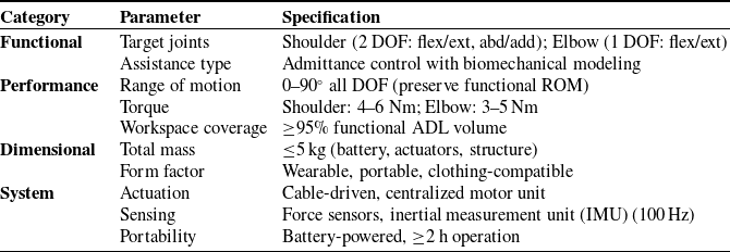


 WCi
WCi Riy
Riy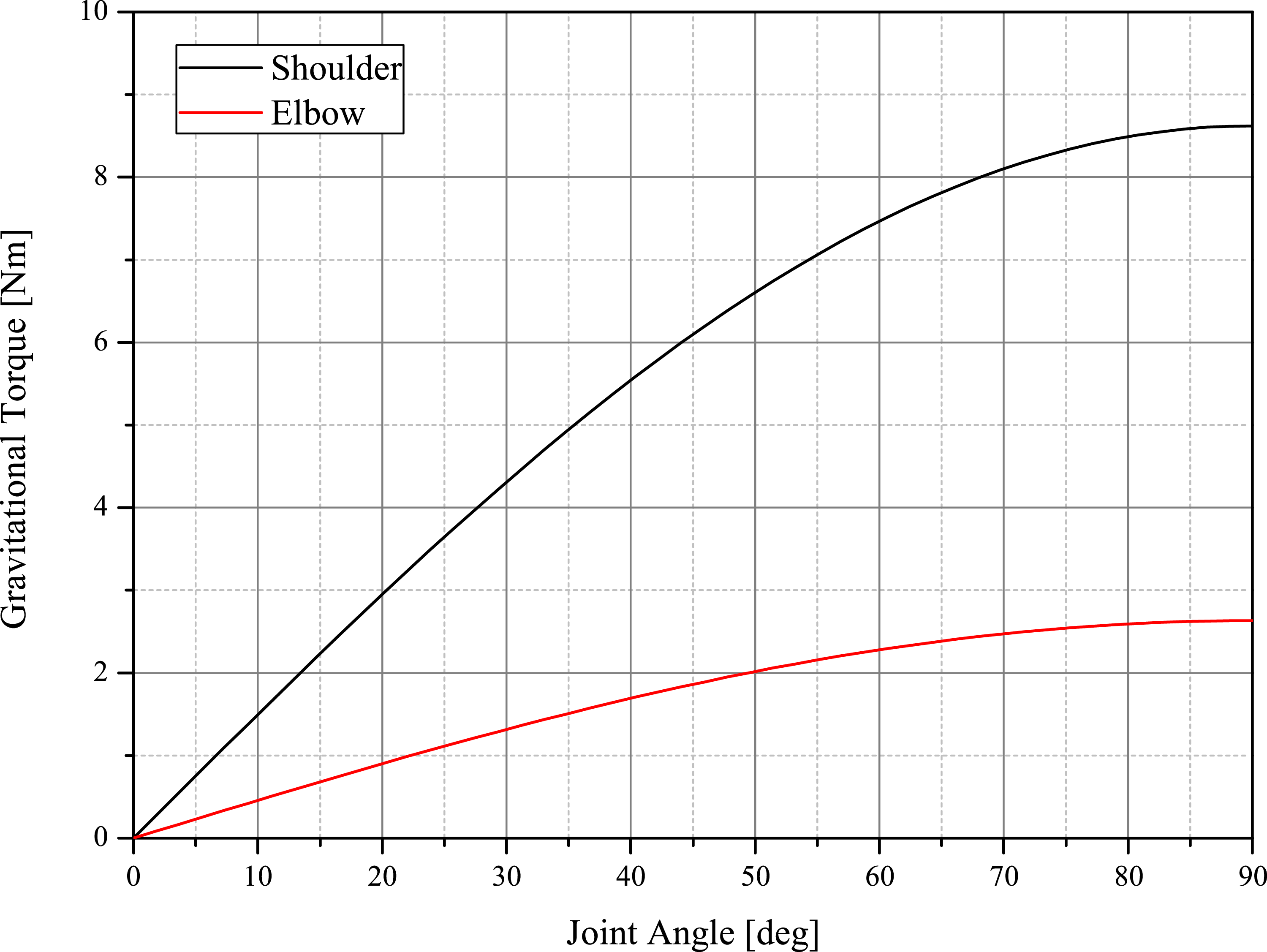
 0∘
0∘ 90∘
90∘ body
body 90∘
90∘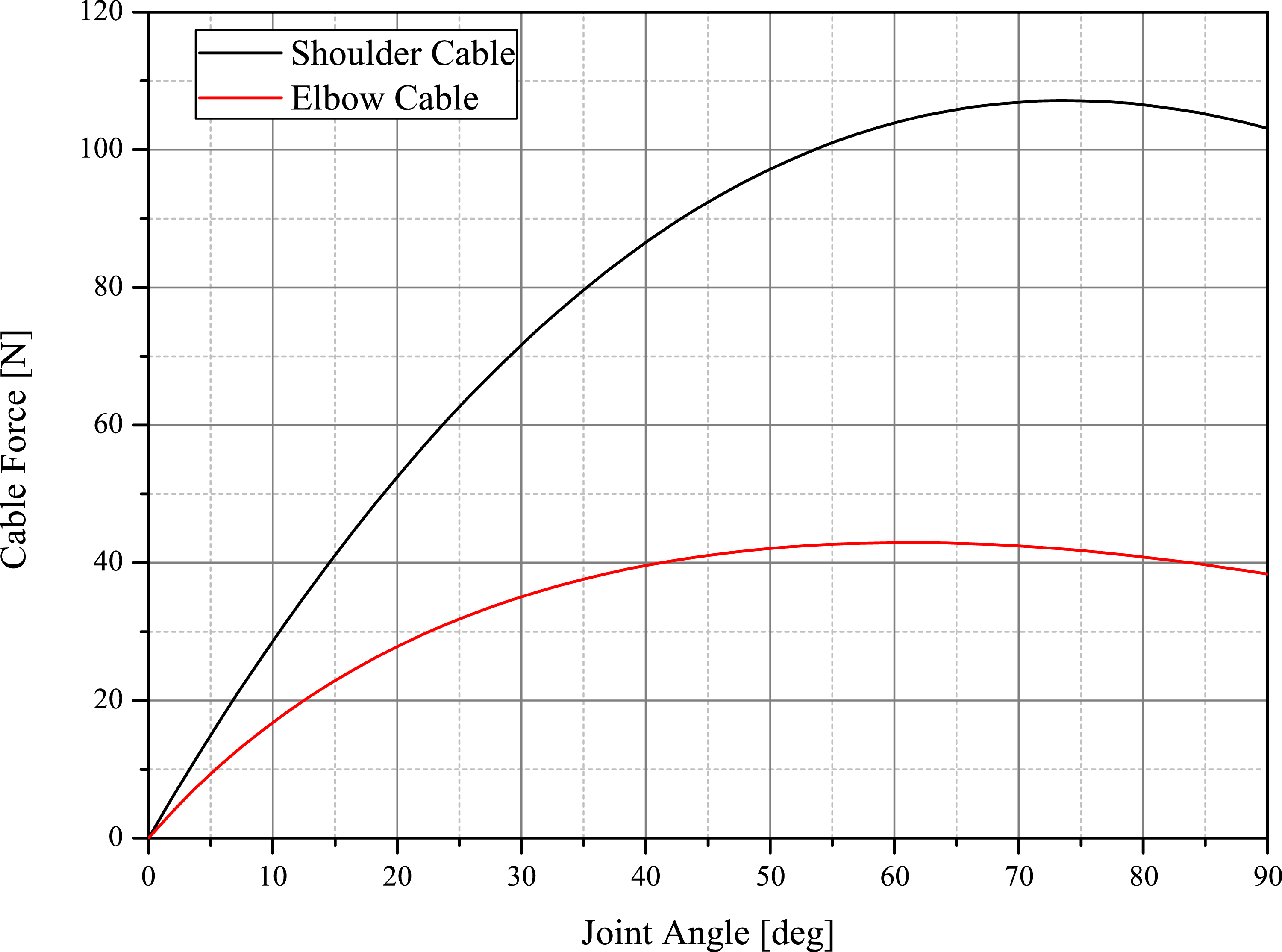
 0∘
0∘ 90∘
90∘ τgravity/r(q)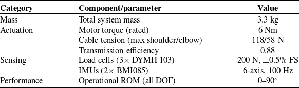


 k1∗
k1∗ k2∗
k2∗ γ∗
γ∗ β∗
β∗

 τr
τr τi
τi β
β α
α β
β θ
θ ωref
ωref


 2
2
 90∘
90∘


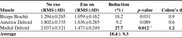
 αcorr=0.017
 †
†


 90∘
90∘

 Open access

