


1. Introduction
Sensor failure is a common occurrence in robotic systems and research efforts have been made to adapt them for such occurrences. In visual simultaneous localization and mapping (vSLAM) systems, where vision sensors are fundamental to the operation and success of vSLAM activities, vision sensor failure causes the whole system to fail as localization and mapping depend on the image content captured by vision sensors. In this paper, a navigation approach is presented that takes care of the robot after the vision sensors have failed. This navigation approach is here referred to as blind navigation.
During vSLAM activities, the path traversed by the robot is compared to a signal that is being generated by a system thereby providing an opportunity to use the Shannon Nyquist theorem to selectively sample data from the robot motion for later use when the robot experiences vision sensor failure. According to the Shannon Nyquist theorem, “if a system uniformly samples an analog signal at a rate that exceeds the signal’s highest frequency by at least a factor of two, the original analog signal can be perfectly recovered from the discrete values produced by sampling” [Reference Anis, Gadde and Ortega1]. In line with the theorem, it was considered that if the variables that can adequately describe the path are discreetly sampled during the vSLAM mapping stage, the robot can use those variables to get back where it started from without human intervention. The robot targeted in this research is a wheeled differential drive robot commonly used in vSLAM research.
To achieve the objective of getting the robot back to where it started in case of vision sensor failure, the path traversed was characterized by two segment types: straight and curved segments, where each segment is differentiated by the yaw angle change in an assumed planar motion. Significant amount of yaw angle change accompanies curved segments while straight segments have less significant change in yaw angle values.
Research efforts were centered on using the path that was previously used by the robot when it experiences vision sensor failure without any recourse to the map developed by vSLAM but using variables that were sampled during mapping. Two motion control strategies based on sampled variables were developed and used, the sampled time-based motion control, in which velocity combinations are published to motor drives for the duration of the sampled time and the traveled distance-based motion control, which uses sampled distances and velocity combinations to traverse the previously used path.
Current vSLAM systems typically do not store data in a format that is readily usable by other sensor types, e.g., IMU sensors. Hence, a novel layer is proposed to be added to the vSLAM system to store readily usable data and use it when vision sensors fail. Due to the limited memory space of a typical low-end robot, and since vSLAM systems typically use substantial amounts of memory, lightweight variables have been selected that take up less memory space.
ROS (robot operating system) is used as the software architecture for implementation of the strategies. In this software version, the messaging system used when sampling path variables is the publish and subscriber, with a demonstrated similar capability when ROS services are used. When using messages, the publisher sends a message to the subscriber at a set frequency and to change the frequency for publishing messages, the changes in the robot yaw angle values are constantly monitored by software means.
Due to changes in ambient lighting condition such as a sudden power failure, mapping failure may result. The robot may be in a location where it is not retrievable by humans, e.g., in healthcare facilities where contact between patients and staff should be minimal such as in COVID-19 [Reference Fang, Mei, Yuan, Wang, Wang and Wang2] cases. Such scenarios constrain the operator to use other means to recover the robot.
The proposed approach will be particularly useful for indoor settings where access to GPS signal may not be available.
Thus, how can a vSLAM system implemented on a mobile platform use its vSLAM-generated data to get back to where it started when it loses its visual capabilities or the vision sensors malfunctions, without using the vision sensor which it used to generate the map? To answer the research question, the following considerations were made.
-
The path is mapped by the robot when the robot’s visual system is functional to perceive the environment.
-
The path generated during vSLAM is categorized into two segments, straight and curved segments.
-
The path mapped during vSLAM activities can be represented by variables generated during vSLAM activities.
-
The variables that represent the path can be used to control motion of the robot without the aid of visual sensors.
-
Obstacles perceived in the environment during vSLAM activities can be defined in terms of either the time taken to avoid them such that $t\in [0,\mathrm{\infty })$
or the distance covered when avoiding the obstacle
$d\in [0,\mathrm{\infty })$
during blind navigation for purposes of motion control.
$t\in [0,\mathrm{\infty })$
or the distance covered when avoiding the obstacle
$d\in [0,\mathrm{\infty })$
during blind navigation for purposes of motion control. -
The environment is static for navigation purposes.


The contributions of this paper are as follows:
-
1. The addition of a layer to ROS-based vSLAM systems for navigating the robot to the base station in case of loss of visual capabilities due to changes in ambient lighting conditions or loss of the vision sensor during vSLAM missions.
-
2. An approach towards mobile robot recovery using data generated during vSLAM activity in case of vision sensor loss.
The rest of the paper is structured as follows: related work (literature review), materials and methods, and programming considerations, experiments and results, and conclusions.
2. Related work
A mobile robotic system can be equipped with many sensors to take on the challenges faced in the environment it is exploring. However, from the reviewed literature, low-end vSLAM systems typically have a smaller selection of sensors that can be used for the system to recover if the vision sensor malfunctions or loses visual capabilities. In their review of sensors used for SLAM, Chong et al. [Reference Chong, Tang, Leng, Yogeswaran, Ng and Chong3] noted that the basic framework of SLAM is odometry, landmark prediction and extraction, data association and matching, pose estimation, and map update. They also concluded that visual sensing provides rich image data but has a significant amount of noise and uncertainty.
The visual sensor is the primary sensor for vSLAM to perform its function of estimating the camera pose and develop the map. Hence, methods have been proposed to aid in the development of the maps and pose estimations which deals with the uncertainties and noise. One such approach is the incorporation of IMU sensors to complement the data estimated from images.
Two prominent approaches to achieve vSLAM are direct and indirect methods. These approaches rely on the brightness consistency constraint which means that the brightness of the environment in which images are captured does not change significantly. However, in real-world environments changes in brightness can occur at any time. Therefore, to overcome the challenges posed by variations in brightness, methods that are robust in image acquisition and preprocessing at the front-end stage of vSLAM are used. The underlaying principle in these methods is to use already captured images and process them to overcome deficiencies brought by changes in illumination.
One method proposes to control the camera exposure time as a means of controlling illumination [Reference Kim, Cho and Kim4, Reference Kim, Cho and Kim5]. Unlike processing already acquired images, the proposal was to compute an optimal time for camera exposure [Reference Zhang, Forster and Scaramuzza6]. In their research, a new metric for computing image contrast was devised since most vSLAM use image gradient-based features. However, there are limited applications to this approach. Moreover, cameras with user configurable exposure time controllers, though preferred, are not typically available on low-end robots.
In other research, mathematical models that compensated for brightness changes were introduced to improve vSLAM performance. These models include proposals that are based on Lambertian reflection, modeling of the optical effects of image sensors and lenses, and modeling of local brightness changes. In Lambertian reflection models, the underlying assumption is that brightness changes uniformly over the entire image. When modeling optical effects of an image sensor and lens, the intrinsic parameters of the imaging sensor and the lens are considered. The imagining sensor and lens are modeled to compensate for intrinsic factors of the camera model and are identified as contributing factors to the vignetting effect [Reference Bergmann, Wang and Cremers7]. On the other hand, to model local brightness, the image is divided into regions followed by considering each region independently as an affine model [Reference Jung, Heo and Park8]. All these research efforts have helped vSLAM to have a better view of the environment in which they operate by rendering image content that can be easily processed by vSLAM.
2.1. Core components of existing vSLAM systems
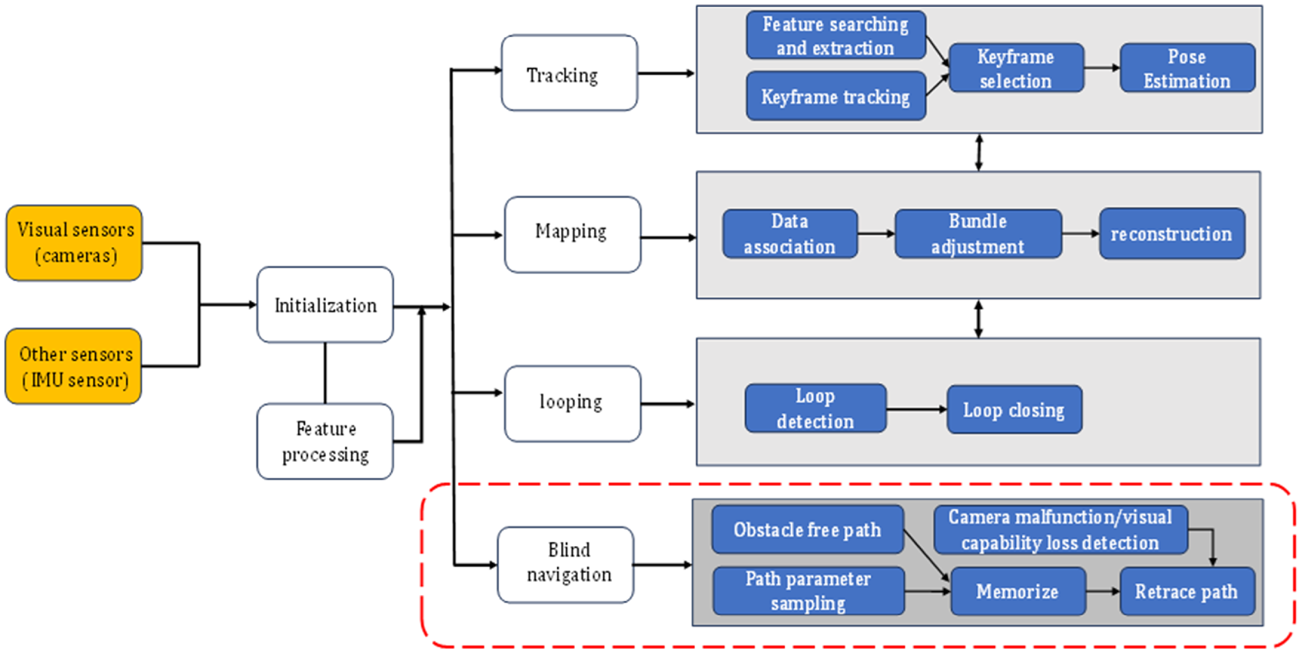
Literature shows that vSLAM systems have five main components [Reference Zhang, Liu, Shen, Zhou and Liu9, Reference Chen10] and the camera and other sensors that aid vSLAM will dominate [Reference Tourani, Bavle, Sanchez-Lopez and Voos11]. Examples of vSLAM systems that use more than one sensor for vSLAM include ORB-SLAM3 [Reference Campos, Elvira, Rodríguez, Montiel and Tardós12], Kimera [Reference Rosinol, Abate, Chang and Carlone13], RTAB-Map [Reference Labbé and Michaud14], etc. Despite having different numbers of vision sensors, there are five core components that make up a vSLAM. These components are vision system (cameras), front-end, back-end, loop closing, and mapping. Each component contributes to the overall function of the vSLAM. However, if the camera vision system does not work, the other components are affected and the vSLAM activities come to a halt. Vision sensors mostly used in vSLAM include monocular, stereo, RGB-D, and panoramic cameras [Reference Chong, Tang, Leng, Yogeswaran, Ng and Chong3].
The front-end in vSLAM is responsible for acquiring data from the images captured by cameras and models it for estimations. In the front-end, processes involve feature extraction and data association. Data associations can be short term, in which a feature in the environment is tracked between two consecutive frames or can be long-term where loop closure is used. All front-end processes rely on algorithms that operate on image data acquired from vision sensors.
The back-end is responsible for optimizing the map generated by vSLAM and plays a crucial role in correcting accumulated errors during vSLAM activities. During vSLAM activities, if the robot visits the same place at least twice and recognizes that location, a loop is closed. Using the recognized location, the map generated can be optimized and accumulated errors reduced. Error reduction is achieved by minimizing the error between the estimated camera trajectory and the actual camera trajectory using loop closure constraints. The mapping section builds and renders a map of the environment based on the estimated trajectory with input from loop closing, front-end, and back-end.
2.2. Strategies for recovery of robotic systems
According to Brooks et al. [Reference Brooks, Begum and Yanco15], recovery strategies for mobile robotic systems are categorized into task support and human support, while Liu et al. [Reference Liu, Li, Zhang and Huang16], categorized them into robot-initiated and human intervention strategies. In the task support recovery strategy, proactive behaviors are used by the failed robot to continue supporting completion of the task. During the entire process, the human operator is responsible for the robots operation. In the human support strategy, the autonomous robot provides information to humans that enhances or bolsters situational awareness regarding the failure and current state of the task being executed. The two categories of the recovery strategies are to a great extent dependent on task, context, and severity of failure [Reference Brooks, Begum and Yanco15].
In the research by Aghili [Reference Aghili17], robot recovery was achieved by developing different control actions which can be used to control the robot when the robot has partial or complete vision failure in the short term. This approach is only applicable to stationary robots.
In the work by Zhang et al. [Reference Zhang, Yang, Kong, Chen, Fu and Peng18], failure of a robotic system is defined as a situation where a device is unable to execute its designated functions under defined circumstances. Using their definition, they developed a fault-tolerant control scheme using Gaussian radial basis function for actuators using neural networks. However, this approach is only validated on simulated works.
Another approach toward failure recovery in robots is proposed by Cordie et al. [Reference Cordie, Roberts, Dunbabin, Dungavell and Bandyopadhyay19]. Their approach is based on reconfiguration of either locomotion or the design structure of the robot configuration. In locomotion reconfiguration, the mobile robot continues to operate with failed actuators by shifting the instantaneous center of rotation. The locomotion reconfiguration is achieved by using a reconfigurable controller to achieve the changes in the instantaneous center of rotation. In design reconfiguration, the robot is designed with emphasis on modularity such that when a module on the robot fails, it is ejected while the robot continues to perform its function.
Khelloufi et al. [Reference Khelloufi, Achour, Passama and Cherubini29] developed a framework for sensor-based navigation of an omnidirectional robot dealing with visual occlusions. Their framework uses LiDAR scanners to navigate to a visual target while handling occlusions using the LiDAR sensor.
3. Materials and methods
The ROS software was used as a case study for implementation of blind navigation since it is already adopted in vSLAM systems such as RTAB-Map [Reference Labbé and Michaud14], and its performance has been compared with other vSLAM systems [Reference Merzlyakov and Macenski20]. Every ROS-implemented system has the navigation stack [21]. The navigation stack has nodes with specific implementations on a particular robot platform. In this research, a demonstration is made on how to implement a recovery mechanism for a robot platform used in vSLAM when the vSLAM losses its visual capabilities by using odometry source, sensor sources, and the base controller of the navigation stack.
During vSLAM activities, visual information is presented to the robotic system through the sensor topics associated with sensor sources in the navigation stack, while odometry related data is presented to the robotic system through the odom topic using nav_msgs/Odometry messages. Messages sent to the base controller make the robot move in the environment it is operating in.
The context of the proposed approach is that when a vSLAM is operational, the environment can be perceived using the camera(s). Therefore, obstacles can be clearly identified. At this stage, the robot can move in an obstacle-free path. After visual loss, the odometry source and the base controller are available to move the robot in the previously used path.
At the time of writing this paper, Turtlebot2i [Reference Labbé and Michaud14] was one of the few commercially available robotic system having ROS for vSLAM implementation. It is the platform used for this research.
In the following sections, considerations made in the implementation of a layer for blind navigation in case of loss of visual capabilities are presented.
3.1. Theoretical considerations for back travel after visual sensor failure
When the robot is moving in the environment during vSLAM activities, it is assumed to have capabilities to identify obstacles and free spaces. If the movements can be quantified by the pose of the camera, it can be quantified by rotations and translations as in Figure 1. The estimations of rotations and translations are done using image content.
Illustration of frames captured during vSLAM activities with time stamps, translations, and rotations.
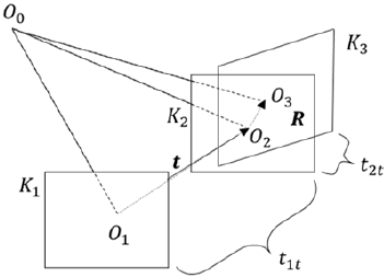
If $K_{1}, K_{2}$
and
$K_{1}, K_{2}$
and $K_{3}$
are frames, the camera can be considered to have translated
$K_{3}$
are frames, the camera can be considered to have translated $\boldsymbol{{t}}$
and rotated
$\boldsymbol{{t}}$
and rotated $\boldsymbol{{R}}$
. The time taken to translate and rotate is
$\boldsymbol{{R}}$
. The time taken to translate and rotate is $t_{1t}$
and
$t_{1t}$
and $t_{2t}$
respectively and the velocities (linear and angular) at which the camera move in the environment are
$t_{2t}$
respectively and the velocities (linear and angular) at which the camera move in the environment are $v_{i}$
and
$v_{i}$
and $\omega _{i}$
. If these variables are considered when the vision system is functional, the robot will be able to trace its path back to where it started if the following variables are kept in the memory
$\omega _{i}$
. If these variables are considered when the vision system is functional, the robot will be able to trace its path back to where it started if the following variables are kept in the memory $M$
for later use.
$M$
for later use.
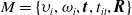 \begin{equation} M=\left\{\upsilon _{i},\omega _{i},\boldsymbol{{t}},t_{it},\boldsymbol{{R}}\right\} \end{equation}
Note that, in the system presented, the source on which these parameters are based is not prescribed. It can therefore be derived from the vSLAM system, or acquired from additional sensors, e.g., IMU. However, the following should be considered:
-
When the trajectory of the robot is estimated from images, it accumulates errors which are only corrected at loop closure [Reference Kasyanov, Engelmann, Stückler and Leibe22 Reference Gálvez-López and Tardos,23]. Therefore, it is not advisable to use the image data as failure may occur before the estimated trajectory is optimized.
-
Some vSLAM systems are keyframe-based. Hence they employ keyframe selection strategies that differ from one vSLAM to the other such as [Reference Mur-Artal and Tardós24–Reference Muñoz-Salinas and Medina-Carnicer26]. Therefore, visual data between keyframes will generally be ignored during map development and may not provide sufficiently frequent data for blind navigation.
-
Image data during vSLAM will contribute to identification of an obstacle-free path.
The rotation matrix $\boldsymbol{{R}}$
may be parameterized by three angles: roll
$\boldsymbol{{R}}$
may be parameterized by three angles: roll $(\phi )$
, pitch
$(\phi )$
, pitch $(\theta )$
, and yaw
$(\theta )$
, and yaw $(\psi )$
. Since planar motion for the mobile platform is assumed, pitch and roll are ignored and the yaw angle remains
$(\psi )$
. Since planar motion for the mobile platform is assumed, pitch and roll are ignored and the yaw angle remains $(\psi )$
. The translations are represented as Euclidean distance (
$(\psi )$
. The translations are represented as Euclidean distance ( $d$
), derived from
$d$
), derived from $\boldsymbol{{t}}$
, while the time
$\boldsymbol{{t}}$
, while the time $t_{it}$
becomes the sampling period
$t_{it}$
becomes the sampling period $T$
and is related to frequency in equation (3). Therefore, the variables are kept in the memory
$T$
and is related to frequency in equation (3). Therefore, the variables are kept in the memory $M$
such that.
$M$
such that.
 \begin{equation} M=\left\{\upsilon, \omega, d,T, \psi \right\} \end{equation}
These variables are sufficient to control planar motion of the mobile platform when the visual capabilities of the vSLAM are lost. It is assumed that the robot navigated an obstacle-free path with the vSLAM system, while the record of $M$
in equation (2) is kept as the mobile platform moves in the environment. The path the robot traverses is treated as a signal. The assumption helps in framing a strategy, guided by Shannon Nyquist sampling theorem, to sample the five variables that will be used for back travel.
$M$
in equation (2) is kept as the mobile platform moves in the environment. The path the robot traverses is treated as a signal. The assumption helps in framing a strategy, guided by Shannon Nyquist sampling theorem, to sample the five variables that will be used for back travel.
3.2. ROS software considerations for blind navigation
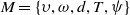
In both ROS1 and ROS2, their fundamental architectures, i.e., publish-subscribe messaging model (using publisher and subscribers), services and actions were considered for implementation of an additional layer to the vSLAM. While ROS1 uses cpp as its middleware, ROS2 uses rcl. In both versions, important components needed for the implementation of the blind navigation layer were established. A brief comparison based on the two ROS versions is shown in Table I.
Brief comparison between ROS1 and ROS2 architectures needed for blind navigation.
The general characteristics of the software that can be used by this approach should have certain capabilities such as:
-
Data should be readily available (continuous flow of data).
-
Provide image data to generate an obstacle-free path. The process should stop when the image stream(s) is not available.
-
Processes should have adjustable times to process when the need arises.
-
Ability to abruptly change the rate at which messages are published based on dynamic conditions such as change in yaw angle values.
3.3. Path generation during vSLAM activities
With the reasons mentioned above, it is therefore important to coordinate image data with motion to map a path generated by the robot during vSLAM activities. Data from the sensors representing the path are recorded in a selective manner with emphasis on points that adequately represent the path and their interpretation is based on ROS standards. For a robotic system implemented on ROS, interpretation of the coordinate systems and their respective units can be found here [27, 28].
To use the selected variables at a later stage, they are recorded and kept in memory. How can this be achieved on ROS? ROS has a messaging system in which at least two software components called nodes send and receive messages using defined topics. The originator of the message is called the publisher and the receiver is called the subscriber. This is called publisher-subscriber mechanism illustrated in Figure 2 with an addition of the activity for saving data to the memory.
An illustration of publisher and subscriber node implementation on ROS.
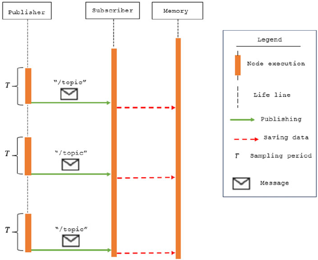
The sampling period $(T)$
is the periodic time in which the publisher sends a message to the subscriber and can be adjusted using the ros::Rate application programming interface (API). The value supplied to ros::Rate changes the frequency at which messages are published. The relationship between frequency and sampling period is shown in equation (3). Therefore, the adjustment can be programmed to take effect when certain conditions are met at runtime. In this research, the yaw angle was monitored and used to trigger the change in sampling period by software means.
$(T)$
is the periodic time in which the publisher sends a message to the subscriber and can be adjusted using the ros::Rate application programming interface (API). The value supplied to ros::Rate changes the frequency at which messages are published. The relationship between frequency and sampling period is shown in equation (3). Therefore, the adjustment can be programmed to take effect when certain conditions are met at runtime. In this research, the yaw angle was monitored and used to trigger the change in sampling period by software means.
 \begin{equation} f=\frac{1}{T} \end{equation}
The messaging system is here exploited in two ways: 1) keep frequency constant and 2) vary the frequency to increase or decrease the sampling period. When the frequency is increased or decreased, the rate at which the messages are sent is affected accordingly. The subscriber upon receiving the message should be able to do two things. Firstly, access to sensor data should be always guaranteed such that when the message is processed the subscriber saves the captured values. Secondly, the subscriber should provide capabilities to save the collected sensor data values. These capabilities are programmed in the nodes. For the ROS platform, the sensor data is available from nav_msgs/Odometry and through sensor topics. Hence, while the messages are published and subscribed, the five variables representing the path are sampled from the respective sensors and saved accordingly.
3.3.1. Where to find path variables
The variables that describe the path are here collectively called path landmarks. They can be expressed as a column vector $\boldsymbol{{x}}_{t\rightarrow kT}^{T}=[\upsilon, \omega, d,T,\psi ]^{T}$
. These variables must be determined from suitable sensor sources based on a given system.
$\boldsymbol{{x}}_{t\rightarrow kT}^{T}=[\upsilon, \omega, d,T,\psi ]^{T}$
. These variables must be determined from suitable sensor sources based on a given system.
In ROS, the linear ( $\upsilon )$
and angular velocities (
$\upsilon )$
and angular velocities ( $\omega )$
can be sampled from the callback function using nav_msgs::Odometry::ConstPtr as the parameter of the function. The pointer is then used to extract two velocity components, the linear velocity in the x-axis and the angular velocity in z-axis from the twist velocities. Similarly, the distance is calculated from coordinates extracted from the callback function using nav_msgs::Odometry::ConstPtr as the parameter of the function. The x and y coordinates are obtained from the pose messages and used to calculate distance. The yaw angle (
$\omega )$
can be sampled from the callback function using nav_msgs::Odometry::ConstPtr as the parameter of the function. The pointer is then used to extract two velocity components, the linear velocity in the x-axis and the angular velocity in z-axis from the twist velocities. Similarly, the distance is calculated from coordinates extracted from the callback function using nav_msgs::Odometry::ConstPtr as the parameter of the function. The x and y coordinates are obtained from the pose messages and used to calculate distance. The yaw angle ( $\psi )$
is obtained from geometry_msgs/Pose2D messages but must be converted from quaternions to Euler angles. The sampling period
$\psi )$
is obtained from geometry_msgs/Pose2D messages but must be converted from quaternions to Euler angles. The sampling period $T$
is set by the programmer in ros::Rate API and can be adjusted at runtime using conditions that monitors the changes in yaw angle values during forward motion.
$T$
is set by the programmer in ros::Rate API and can be adjusted at runtime using conditions that monitors the changes in yaw angle values during forward motion.
3.3.2. Path segments and representations
The sampled path during vSLAM activities is divided into curved and straight segments because of their difference in curvature. Fewer sampled points can be used to reconstruct a straight line than the curved path segment. Additionally, the sampling period is used to differentiate the two path segments during path retracing. When the publish-subscribe mechanism illustrated in Figure 2 is used, it implies that the frequency of sending messages must change for straight and curved segments with an increase in frequency for curved and reduction for straight line segments.
The changes in sampling rate must be triggered by certain variable(s) constantly observed during robot motion. The yaw angle gives a meaningful observation of the changes in robot motion. The measure of the amount of turn is normally by use of angles. For the robotic system, turns are often presented in quaternions (as is the case with the Turtlebot2i used in this research) and therefore must be converted to yaw angles. Once converted, they can be used to measure the amount of turn. Since the publisher is responsible for generating messages, it constantly monitors the yaw angle changes and adjusts the frequency accordingly. Additionally, the publisher must send to the subscriber both the yaw angle and the periodic time ( $T$
) to be saved with those collected for both linear and angular velocities.
$T$
) to be saved with those collected for both linear and angular velocities.
In using the yaw angle to monitor whether the robot is on a curved path segment, the following conditions are used to change the sampling period:
-
If consecutive yaw angles (
$\psi )$
when subtracted give only positive values. -
If consecutive yaw angles (
$\psi )$
when subtracted give only negative values. -
If consecutive yaw angles when subtracted give either positive or negative values and at least one difference between yaw angles gives either a positive or a negative value in the range
$\pi \leq \psi \leq 2\pi$
or
$-\pi \geq \psi \geq -2\pi$


If none of the conditions are satisfied, the path is considered a straight segment. When any of the conditions are met, changes to the sampling period are effected. Four consecutive angles are used to have three values for the difference between consecutive values. This helps in breaking the tie for subtracted values.
The path used by the robot can therefore be represented in two ways by using the five variables or using the yaw angle changes between two consecutive points. For the five sampled variables, the sampling period will have the lowest value for a curved path segment. When represented with increasing or decreasing values of yaw angle differences, the path can be used to correct the heading direction at every sampled point (see Figure 3). However, for the robot to move to the next point sampled velocity combinations are used.
Path representations for blind navigation.
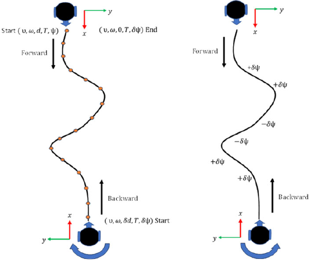
On ROS platforms, yaw angles increase with anticlockwise rotation and decrease with clockwise rotation [27]. Additionally, a positive value of angular rotation $(\omega \gt 0)$
will result in increasing yaw angle values, while negative value of angular rotation
$(\omega \gt 0)$
will result in increasing yaw angle values, while negative value of angular rotation $(\omega \lt 0)$
will result in decreasing yaw angle values.
$(\omega \lt 0)$
will result in decreasing yaw angle values.
3.3.3. Path recording using ROS topics and ROS services
There are two alternatives that were considered when recording path variables. The two are either by using ROS messages as earlier highlighted or using ROS services explained here. The significant difference between ROS messages and ROS services is that services have a feedback mechanism and initiation of a request is event driven.
In both ROS messages and ROS services, access to sensor data is through nav_msgs/Odometry messages and sensor topics of the standard navigation stack. Furthermore, the initiator of the message monitors yaw angle values and change the frequency of sending the messages when changes in yaw angle arise. Since the service client does not have the capability to automatically send the service requests, an event must trigger a service request. Therefore, a different architecture from that used by publishers and subscribers is used. An alternative architecture is therefore proposed as shown in Figure 4 for sampling and recording path variables using ROS services.
Path landmarks data collection using publisher-subscriber and ROS services during vSLAM activities.
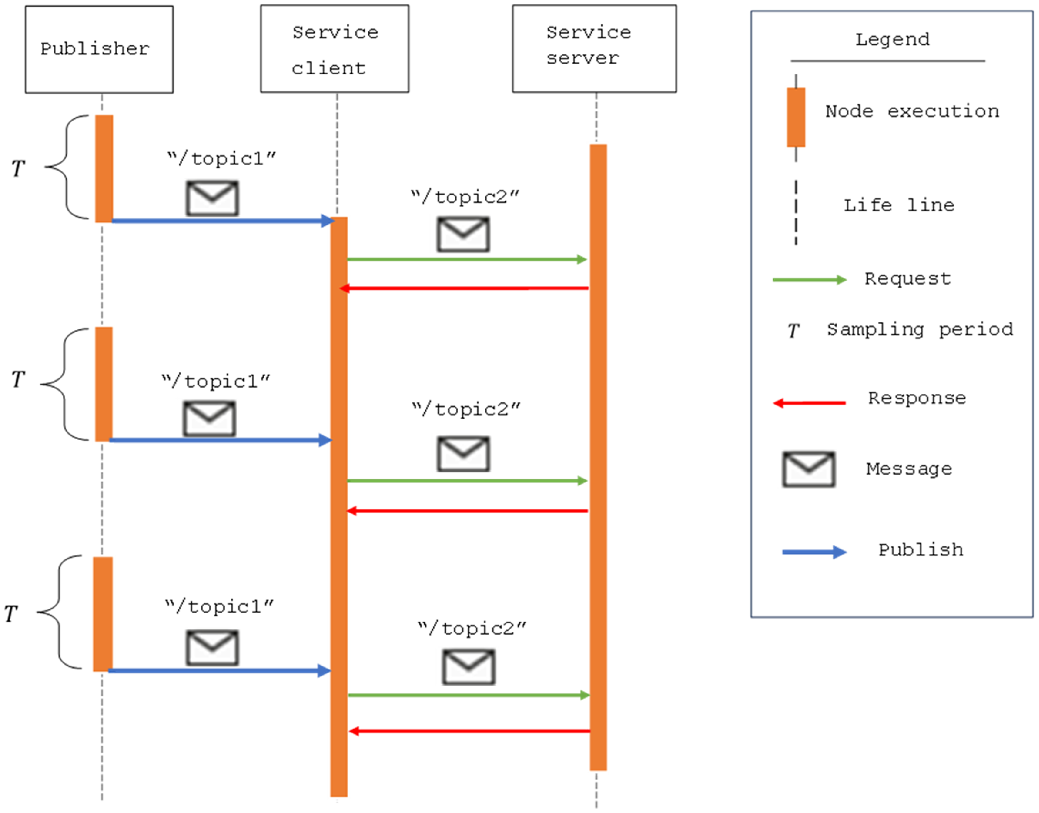
Implementing the proposed architecture requires the following: the service client implemented with the subscriber to receive messages from the publisher using its callback function. One method to implement this architecture is to use a class with the subscriber callback function implemented as a method of the class. The message from the publisher on /topic1 will be received and processed before a request is sent to the servicer server. If image content were to be used, this architecture can incorporate it into the message request to the service server using /topic2. This architecture affords the decoupling of image content from the ego-motion data if necessary.
The publisher must have access to geometry_msgs/Pose2D messages to convert quaternions to Euler angles. Furthermore, the values of the yaw angles are monitored to segment the path into straight or curved segments. The service client uses values monitored for yaw angles to adjust the sampling rate accordingly using ros::Rate.
On the other hand, the service server must access nav_msgs/Odometry messages through the odom topic normally available on ROS-based vSLAM systems and saves both the request message and the sensor data upon receiving the request.
3.3.4. Saving collected path landmarks
The five sampled variables are stored to be later used when the vSLAM system malfunctions or loses visual capabilities. The standard storage for ROS is the parameter server. However, a different storage that eases troubleshooting was adopted. The storage adopted is a YAML file. For this file system to be implemented in a separate folder, in the CMakeLists.txt file in the target_link_libraries(), append yaml-cpp. Similarly, the header file in the node must include yaml-cpp/yaml.h.
The format for saving the path landmarks has two labels; one for uniquely identifying path landmarks and the other for the data collected. The first label showed the sequence in which the path landmarks are increasing. The orderly arrangement of labels makes troubleshooting less stressful and makes it easy to search for the path landmark during motion execution during back travel. The other label enables fetching of the indexed stored values. It can also be expanded to take more variables if the need arises.
To save the data content, the YAML::Emitter was used. For the label to uniquely identify the landmark, YAML::BeginMap with YAML::Key supplying the unique identification label was used. The second map used the YAML::Flow with the variables assigned their place between YAML::BeginSeq and YAML::Endseq. A separate folder was created to contain the files saved, with each file having a file extension .yaml in a separate folder.
3.3.5. Motion control methods after vision loss
Motion control methods for back travel are accomplished by using action server and action client architectures (actionlib). The action client provides goals to the action server in the form of the five variables (equation 2).
The architecture for motion control methods is as shown in Figure 5. Two topics that can be used to control the Turtlebot2i are the /cmd_vel_mux/input/teleop and the /mobile_base/commands/velocity. The action client, using either of the topics, sends goals to the action server. The start of the sending of goals is dependent on receiving a message indicating the camera has lost visual capabilities.
Architecture for motion control during blind navigation.
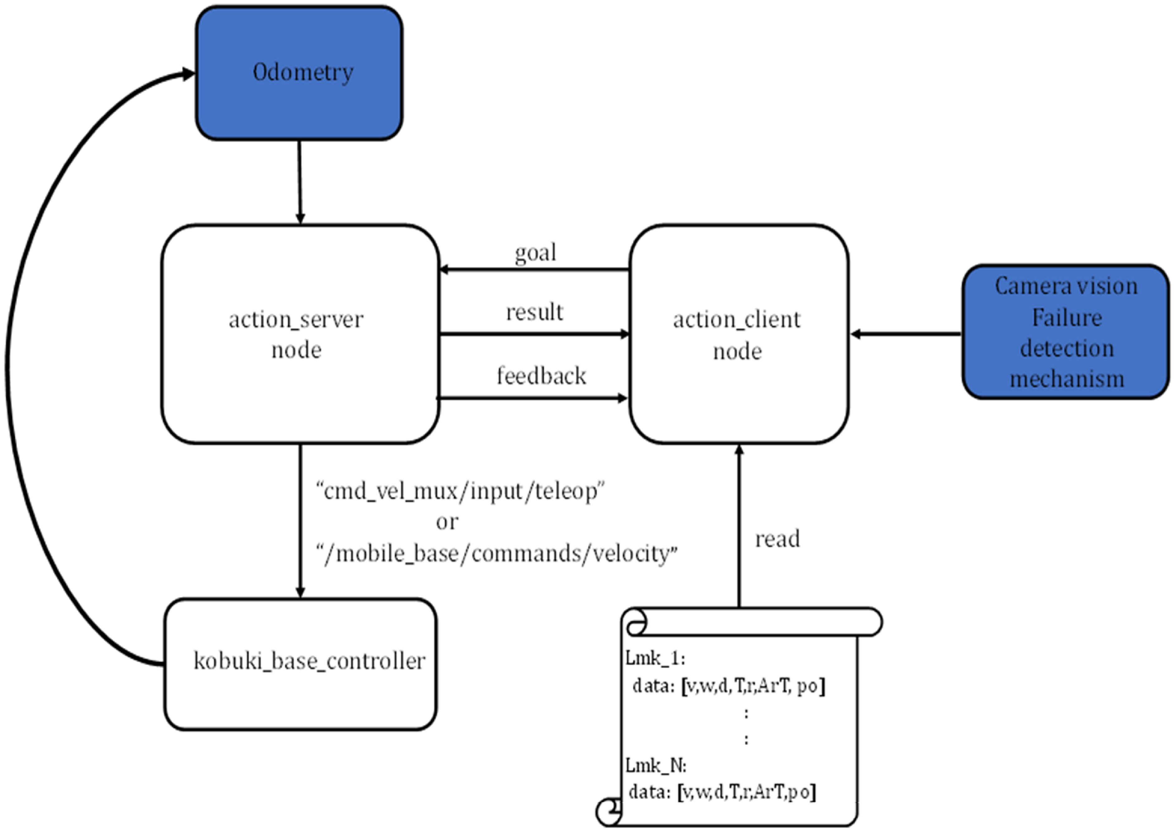
The action server must have access to odometry messages since motion control methods use the distance traveled as the result of the action server (see definition for action messages, Figure 9).
The first method for motion control uses the sampled time to drive the robot. In this method, the sampled period is added to the current time using ros::Time::now()on the robot platform to estimate the duration with which the robot will publish the velocity combinations on the topic. Duration is determined by using ros::Duration (sampled period).
The second method for motion control uses the distance calculated from odometry to estimate the distance when the next path landmark will be used. The computation considers the current distance and the distance that was recorded between two consecutive path landmarks. The recorded distance between two consecutive path landmarks is added to the current distance to estimate the target distance. When the target distance is covered, the result is sent to the action client node.
3.3.6. ROS action server implementation
The action server node should preferably be implemented as a class. This approach enables publishers and subscribers and their callback functions to be used as methods and variables when implementing the motion control logic. The action server can be used with its template as a private variable. Similarly, result and feedback can also be declared as variables and be used anywhere in the class and accessed by methods.
The message sent to the Kobuki_base_controller (of the Turtlebot2i) is the velocity combinations. It sends only linear velocity for straight line segments and a combination of linear and angular velocity for curved segments. The message is composed by using geometry_msgs/Twist and a publisher to publish on the topic /cmd_vel_mux/input/teleop or /mobile_base/commands/velocity. The action server has access to the odometry values through nav_msgs/Odometry messages on the /odom topic.
3.3.7. ROS action client implementation
The action client implementation takes care of preparing path landmarks for execution in the action server. One such action is to determine the distance between two consecutive path landmarks and the rest of actions are shown in Figure 6. These are activities accomplished by the action client node during the processing of the goal to be sent to the action server.
Steps to prepare path landmarks for sending to the action server.
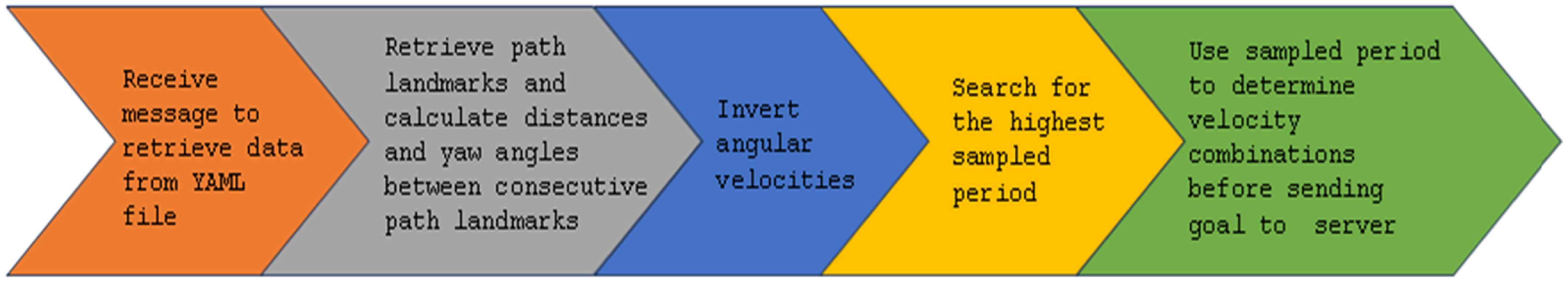
The action client server is implemented as a global variable and a callback function that receives the message to start the processes in Figure 6. The callback function is responsible for receiving the message that triggers the retrieval and processing of the stored path landmarks. Inside the callback function, the YAML::Node and the YAML::LoadFile are used to load the YAML file contents and store them in a C++ structure. The YAML::const_iterator is used to fetch all the path landmarks from the YAML file and save them in the C++ structure in the action client.
3.4. Integration of new layer to existing vSLAM framework
The proposed new layer for back travel was integrated and used on ROS-based RTAB-Map vSLAM. A package was created separate from the RTAB-Map vSLAM system with nodes responsible for data collection, rotation of the robot by $\pi$
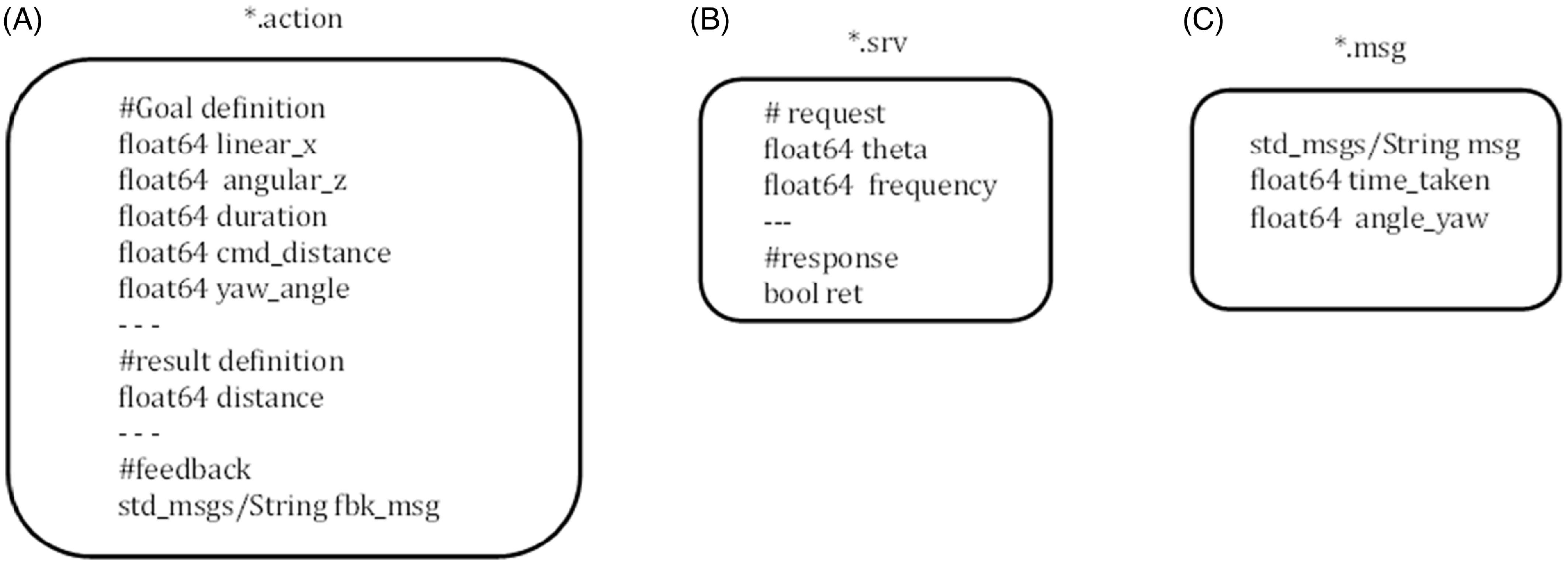
radians, and motion execution. The nodes subscribed to the topics generated by the RTAB-Map vSLAM to receive and process path variables. Data for path variables were received from three messages defined on RTAB-Map, namely nav_msgs/Odometry, geometry_msgs/Pose2D, and geometry_msgs/Twist messages. Additionally, messages, services, and actions used in the nodes were defined as shown in Figure 9.
$\pi$
radians, and motion execution. The nodes subscribed to the topics generated by the RTAB-Map vSLAM to receive and process path variables. Data for path variables were received from three messages defined on RTAB-Map, namely nav_msgs/Odometry, geometry_msgs/Pose2D, and geometry_msgs/Twist messages. Additionally, messages, services, and actions used in the nodes were defined as shown in Figure 9.
The path data generated during vSLAM activities were stored in a human readable YAML file format to be reused after vision loss. The motion during back travel was controlled either by the sampled time or the traveled distance (consider Figure 7). In this paper, the sampled time-based motion control was used.
Sequence for blind navigation during and after loss of visual capabilities in vSLAM.
On other vSLAM systems, the five variables used to represent the path can be collected and used in a similar manner depending on the sources of sensor data. However, as highlighted in the literature review, for low-cost robotic systems, vision sensors, wheel encoders, and IMU sensor dominate in providing data required for vSLAM systems. These sources provide velocity combinations, distance, and yaw angles. The sampling periods can make use of programmed time stamps using the computer clock.
When commanding the robot to move from point to point, the stored data were published on the topic /cmd_vel_mux/input/teleop. The action server and the action client were used to communicate saved data for the robot to move.
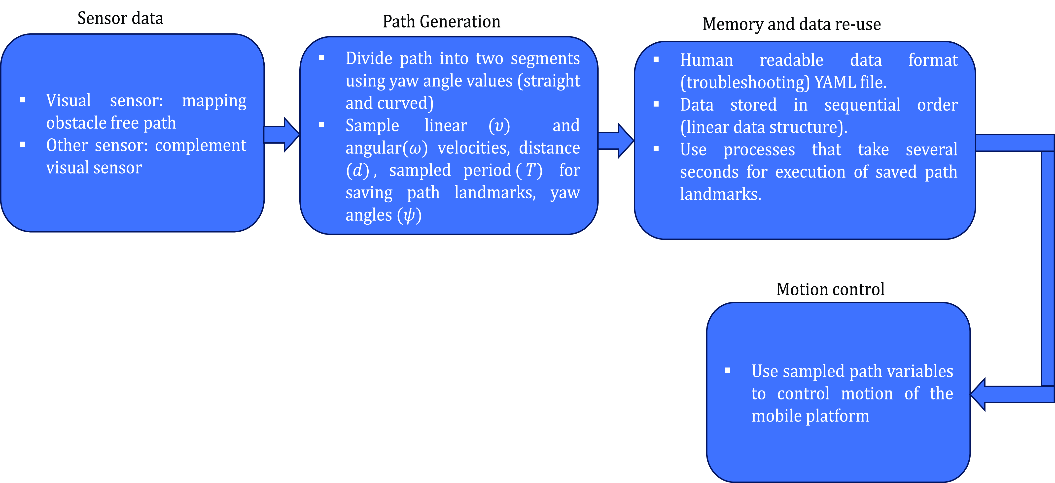
The position of the blind navigation layer when adopted and implemented on vSLAM systems is shown in Figure 8. In the additional layer, path variables are sampled as the robot traverses an obstacle-free path. The path variables are kept in memory until visual capabilities cease to function. The failure of visual sensors causes the SLAM system to fail, this triggers the layer to enable the rotation of the robot by $\pi$
radians and begin to use its recorded data to retrace the path previously used (consider Figure 8).
$\pi$
radians and begin to use its recorded data to retrace the path previously used (consider Figure 8).
VSLAM system with proposed blind navigation layer added.
3.4.1. Message definition
To communicate between publishers and subscribers, action server and action clients, and between service server and service clients, within the new layer messages were defined. The action message sent to the action server by the action client contains all the five variables while the message sent to the subscriber has three variables. The string is used by the callback function before the message is processed. Figure 9 shows definitions for actions (A), service (B) and messages (C).
Definitions for action (A), service (B), and message (C).
3.4.2. Launch of nodes on ROS platform
The launching of the nodes of the newly integrated blind navigation layer is dependent on the operator of the mobile platform. This is because low-end robots with vSLAM systems are memory constrained. Hence, the nodes can be launched when there is absolute need for the system to work after vision loss. If loss of visual capabilities is anticipated, the nodes can be launched, and generally, if the operator does not want to physically fetch the robot, the nodes can be launched at the start of the mission.
ROS has a mechanism for launching nodes. The general guideline is that the vSLAM system should be operating at the time of launch so that the blind navigation layer with its nodes can subscribe to the topics on the vSLAM. Additionally, servers must be launched before the client nodes. The publisher responsible for generating and sending path data should be the last to be launched as it signals the start of recording data for data collection nodes. If both servers and clients are launched at the same time, then client nodes should incorporate code that waits for the servers to run and register their services.
3.4.3. Impact of new layer on performance of the vSLAM
Adding a new layer to RTAB-Map vSLAM had minimal effect on the system, primarily impacting memory usage. However, the impact is negligible due to the use of lightweight storage variables (see data in section 5). Additionally, memory can be allocated as needed before starting a vSLAM mission, similar to how vSLAM logs messages for later troubleshooting.
The process of saving path variables is also less demanding on the vSLAM system since topics that provide path variables to which the layer subscribes are already defined on the vSLAM. Moreover, the three topics that are mostly active in the new layer are for 1) sending messages between publisher and subscriber for data collection, 2) commanding the robot to rotate by $\pi$
radians after vision failure, and 3) publishing goals for moving the robot during back travel.
$\pi$
radians after vision failure, and 3) publishing goals for moving the robot during back travel.
When using the new layer during back travel, the computational demand on the vSLAM system is very minimal since resource-intensive processes like tracking, mapping, and looping are not active, leaving only the new layer active. Additionally, no complex calculations are performed during back travel. Decisions for motion control use comparisons of sampling periods for straight and curved segments and velocity combinations for each respective path segment.
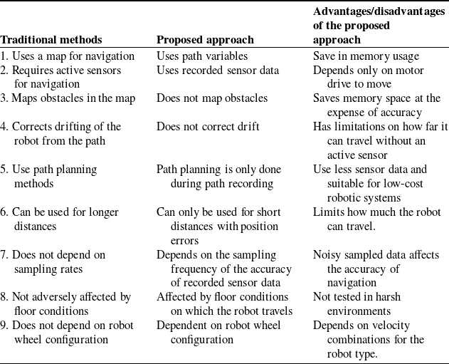
3.4.4. Comparison between traditional navigation methods and the proposed approach
There are some significant differences between the proposed approach and the traditional navigation methods. The main differences are highlighted in Table II. The advantage of the proposed approach is enabling the robot platform to be recovered when vision sensor failure occurs. It is a feature that is currently not available on vSLAM systems.
Comparison between traditional navigation method and new approach.
4. Equipment for experimentation
The equipment used for the experimentation of the developed ROS-based blind navigation is shown in Figure 10. The router provided wireless connectivity between the laptop and Turtlebot2i. The laptop was assigned an Internet Protocol address together with the robot. Then using secure shell (ssh), messages to command the robot motion during vSLAM activities were sent to the robot.
Equipment for experimentation.
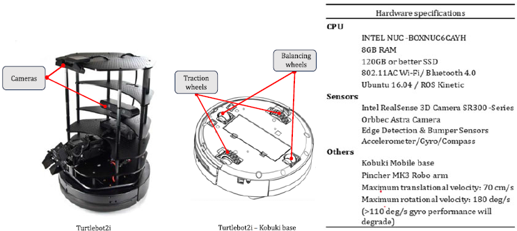
The experimental setup consisted of a marked distance and a few obstacles to avoid in the environment and the robot was allowed to pass through the spaces between obstacles. To simulate camera malfunction or loss of visual capabilities, a message was sent on the command line using the rostopic pub and the topic that communicates the message. The ROS-based RTAB-Map vSLAM was used during experimentation.
5. Experiments and results
The first tests on the hardware performance of the robot were to understand how recorded velocity values affect motion of the robot during back travel. The tests included 1) when to use the linear and angular velocities, 2) the relationships among the variables used for back travel and 3) the effectiveness of using the proposed motion control method called sampled time-based motion control for back travel. In all the experiments, the sampling time for the five parameters was set to 2 s for straight line and 1 s for curved path segments. To differentiate between curved and straight segments, the sampled period was used. The higher sampling value was associated with straight segment and lower value for curved segments. In all the experiments, the memory size of the files was less than 16 KB.
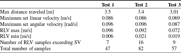
The five tests shown in Table III indicated that when the differential drive robot is set on pure linear velocity an extra angular velocity was also recorded during sampling. The value of the angular velocity was such that as the linear velocity increased, the angular velocity component reduced significantly. Additionally, some recorded linear velocities (RLV), exceeded the maximum set velocity (SV). This happened more often for lower values of SV. Consider Table III. The odometry value is the calculated distance from odometry data and (RAV) is the recorded angular velocity.
Test results for sampled straight line segments.

It can also be observed that as SV value increased in each test, the number of samples reduced in inverse proportion. Furthermore, the RAV values oscillated as the robot moved in the environment.
Based on the observations made from Table III, the robot was made to move in a straight line using the recorded velocities. Firstly, with both recorded linear and angular velocities and then without the angular component. Results showed that when both the RAV and RLV were used, the robot went off course. However, when the RLV was the only velocity component used, the robot followed the path that was previously used (consider Figure 12). Additionally, the position error, i.e., the difference in distance between the distance traveled during vSLAM activities and the distance traveled back after vision failure, gave the results as shown in Table IV.
Position error for back travel using different velocities.
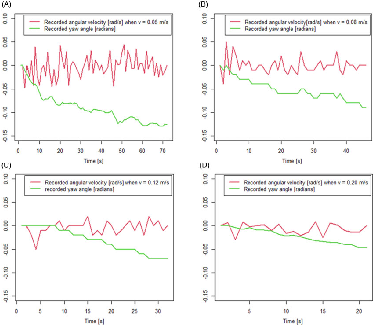
Another test was to demonstrate the effect of linear velocities on the values of the recorded yaw angle values (heading direction). The linear velocities were increased from 0.05 m/s in all the tests conducted. These set velocity (SV) values were 0.05 m/s, 0.08 m/s, 0.012 m/s, and 0.2 m/s. Results showed that as the linear velocities were increased, the values for the recorded yaw angles decreased during back travel. Since the tests were conducted on a straight segment, the implication of the result is that the robot drifts less from its heading direction when moving at elevated linear velocities than lower values. Figure 11 shows the relationship between angular velocity and the yaw angle.
Relationship between angular velocity and yaw angle changes for robot during back travel.
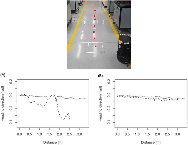
The proposed approach was tested on the Turtlebot2i with the results shown in Figure 12 and Figure 13 for straight and curved segments respectively.
Robot back travel in straight line segment without obstacles $(^{\_ \_ \_ \_ \_ \_ \_ })$
ground truth, and (- - -) back travel.
$(^{\_ \_ \_ \_ \_ \_ \_ })$
ground truth, and (- - -) back travel.
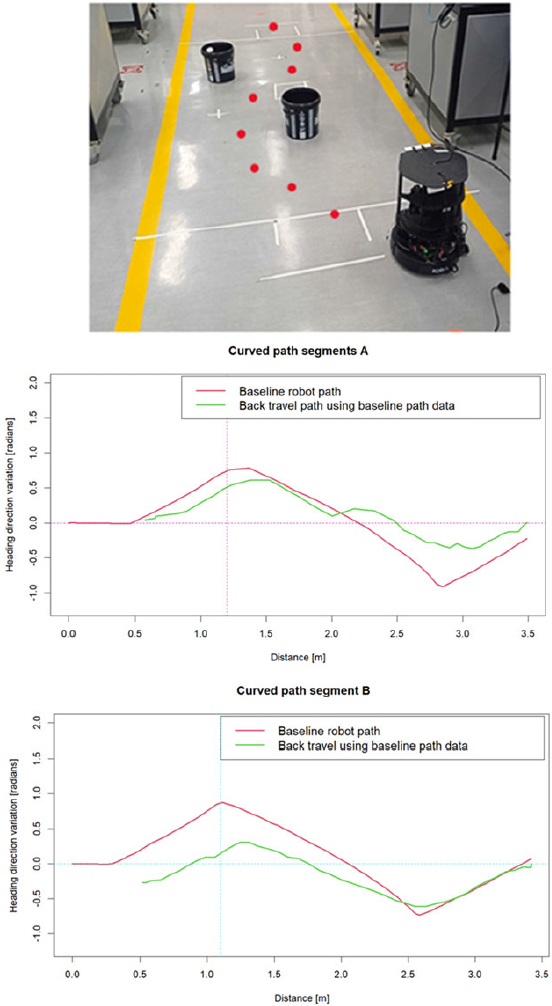
Robot moving in a curved segment with obstacles.
In graph A (Figure 12), the sampled combined linear and angular velocities were published in back travel while in graph B only the linear velocity was published. It can be observed that for straight segments, the motion of the robot is more accurate than when both linear and angular velocities are used.
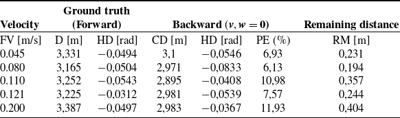
Table IV shows the accuracies in terms of distance between the starting points for different velocities for recorded forward velocity (FV). During back travel, the covered distance (CD) was recorded and the heading direction (HD). The position error (PE) in percentage form was calculated using the formula in equation (4) when divided by its ground truth distance (D).
Given that a path has distance values $d'_{i}$
when the path was mapped and has
$d'_{i}$
when the path was mapped and has $d''_{i}$
for the same distance sampled during back travel, the PE should be very small as expressed in equation (4)
$d''_{i}$
for the same distance sampled during back travel, the PE should be very small as expressed in equation (4)
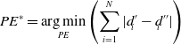 \begin{equation} PE^{*}=\underset{\mathit{PE}}{\arg \mathit{\min }} \left(\sum _{i=1}^{N}|d'_{i}-d''_{i}|\right) \end{equation}
Results demonstrate that for straight segments, all recorded angular velocity should be ignored as the robot tends to drift from the previously recorded path. Additionally, as the linear velocity value (FV) was increased, the position error increased since higher values of SV never reached the maximum set values (see Table III).
For curved segments, both the linear and angular velocities were used. To successfully use the straight and curved segments, the Shannon Nyquist sampling theorem was used in the following ways: 1) The path is considered as a signal that is being generated; 2) The path parameters, i.e., $\upsilon, \omega, d$
and
$\upsilon, \omega, d$
and $\psi$
are sampled at sampling periods that will be used for back travel; 3) The frequency of sampling is such that the straight segments are less sampled than the curved segment; 4) The path segments are differentiated during forward motion using the changes in yaw angle changes; 5) Reconstruction of the path is when the robot uses the saved parameters to get back to the base station. During back travel, the path segments are differentiated by the sampling periods which are such that publishing of velocity combinations is guided by sampling periods. The highest values only publish linear velocities and lowest values, a combination of linear and angular velocity.
$\psi$
are sampled at sampling periods that will be used for back travel; 3) The frequency of sampling is such that the straight segments are less sampled than the curved segment; 4) The path segments are differentiated during forward motion using the changes in yaw angle changes; 5) Reconstruction of the path is when the robot uses the saved parameters to get back to the base station. During back travel, the path segments are differentiated by the sampling periods which are such that publishing of velocity combinations is guided by sampling periods. The highest values only publish linear velocities and lowest values, a combination of linear and angular velocity.
Figure 13 shows the robot avoiding obstacles in its path. In graph A (Figure 13), the robot linear velocity was set to 0.086 m/s, and in graph B (Figure 13), the angular velocity was set to 0.086 m/s with a reduction in the sampling period. For the first test (graph A), the sampling rate was set to 0.5 Hz and curved segment to 1 Hz. For the second test (graph B), the straight segment was sampled at 1 Hz and the curved segment at 2 Hz. Due to the oscillations in the angular velocity, the values used can be over the set limit on the operators’ side and result in curvature that were not anticipated during back travel. Table V shows successful test results for paths with obstacles.
Test results for a curved segment with obstacles.
5.1. Evaluation of the proposed approach
After fully integrating the new layer to the RTAB-Map vSLAM, the results for the practical application of the added layer are shown in Table VI for varying distances. The tests included both straight and curved segments with the distance covered for each test increased. The path width was 1.7 m and the robot started in the middle of the path.
The angular set velocity (ASV) and the linear set velocity (LSV) were set at 0.097 rad/s and 0.086 m/s respectively before the start of the tests. As the robot moved in the environment, the path was sampled at 1 Hz for the curved segment and 0.5 Hz for straight line segments. The recorded angular velocity (RAV) and recorded linear velocity (RLV) for the forward motion are shown in Table VI for each test.
Test results of a new layer added to existing vSLAM.
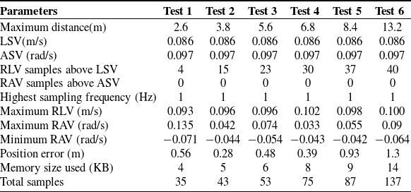
The angular velocity oscillations recorded were significant when the robot moved at low speeds.
It was observed that as the distance increased, the position error increased and the worst recorded position error was 1.3 m when the robot went out of the path width.
The memory usage for sampling data was very minimal and the longest distance covered used 14 KB of memory space. The memory space used is very insignificant when compared to a typical vSLAM system that takes a lot of memory to store point clouds.
Due to the motion control method used, the robot gathers momentum when in motion. Hence, the contribution of RLV that was above LSV was significant and affected the values of the position error besides the angular oscillations.
5.2. Limitations of the approach
The approach here presented has limitations in its applications. 1) These limitations include the environment in which the robot operates. The assumption of a static environment may not always hold. Therefore, dynamic objects can be problematic since they pose challenges both to the vSLAM and the robot. 2) The reliance on the sampled velocity combinations can cause the robot to drift as they do not take into consideration the floor conditions on which the robot passes. Furthermore, the approach’s dependence on velocity combinations means that if the drive system of the robot fails, the robot cannot be recovered using this approach. 3) The approach was tested for an indoor mission. Therefore, an uneven ground resulting into noisy sampled velocity combinations was not tested. 4) If the vision system experiences extreme degradation or failure in one vision sensor, identification of an obstacle-free path may become a challenge. Degradation of the vision sensor has not been studied in this research. It is only vision loss resulting in mapping and localization failure.
6. Conclusions
With the limited number of sensors on a typical low-cost vSLAM system, this research developed an approach to recover a mobile robot in case of vision sensor loss or loss of visual capabilities due to changes in ambient lighting conditions during vSLAM activities in ROS-implemented vSLAM systems. The approach depends on the vSLAM structure and makes the most out of the data generated during vSLAM activities. The approach is independent of the kind of sensor, provided that the sensor(s) can give the required measurements at a sufficiently fast sampling rate. From the ROS software, the publish-subscribe mechanism was used to periodically sample the path landmarks consisting of five variables (linear and angular velocity, distance, sampled period, and the yaw angle) and the actionlib for execution of the saved path landmarks. The choice of lightweight variables is to use less of the memory space as opposed to large memory space normally used in vSLAM systems. The yaw angle was used to determine between straight and curved path segments, with curved segments sampled at higher rate than the straight segments. The value of the sampled periods in memory is then used for motion control during back travel. Higher values of sampling periods are associated with straight segments and lower values associated with curved segment since they are sampled at different rates.
For accurate recalling of the path, straight path segments use recorded linear velocities in back travel while curved segments use the combined linear and angular velocities. Since there is currently no mobile robot recovery mechanism on vSLAM systems after vision sensor failure, this approach affords the means to recover the mobile robot platform in an environment that is static and has no access to GPS signal.
The contributions made by this research are as follows: 1) Addition of a new layer to ROS-based vSLAM systems for navigating the robot to the base station in case of loss of visual capabilities due to changes in ambient lighting conditions or loss of the vision sensor during vSLAM missions. The new layer was added by creating a package and nodes on ROS that subscribed to selected topics used on ROS-based RTAB-Map vSLAM. The nodes were for collecting and saving path variables that represented an obstacle-free path. Other nodes were for turning the robot for $\pi$
radians after vision loss and moving the robot using the saved variables. Data collected and saved by the nodes are available through topics published on the existing vSLAM responsible for odometry and sensor sources. 2) An approach toward mobile robot recovery using data generated during vSLAM activity in case of vision sensor loss. In the approach presented, the Shannon Nyquist sampling theorem was used to guide in the selection and sampling of variables that best represented the path. The path was divided into two different segments, i.e., curved and straight, monitored during vSLAM activities and represented by five lightweight variables for ease of storage and computation. Sampling was achieved using the publish-subscribe mechanism on ROS with varying sampling rates for path segments to increase the accuracy of path reconstruction. Hence, a path traversed by the robot was treated as a signal that can be sampled during forward motion and reconstructed during back travel when vision loss occurs.
$\pi$
radians after vision loss and moving the robot using the saved variables. Data collected and saved by the nodes are available through topics published on the existing vSLAM responsible for odometry and sensor sources. 2) An approach toward mobile robot recovery using data generated during vSLAM activity in case of vision sensor loss. In the approach presented, the Shannon Nyquist sampling theorem was used to guide in the selection and sampling of variables that best represented the path. The path was divided into two different segments, i.e., curved and straight, monitored during vSLAM activities and represented by five lightweight variables for ease of storage and computation. Sampling was achieved using the publish-subscribe mechanism on ROS with varying sampling rates for path segments to increase the accuracy of path reconstruction. Hence, a path traversed by the robot was treated as a signal that can be sampled during forward motion and reconstructed during back travel when vision loss occurs.
Author contributions
CM conceived and designed the study, conducted data gathering, and performed analyses. CM and KS wrote the article.
Financial support
This research received no specific grant from any funding agency, commercial or not-for-profit sectors.
Competing interests
The authors declare no competing interests exist.
Ethical approval
Not applicable.


 Open access