


1. Introduction
The flow driven by buoyancy is called thermal convection, and it plays an important role in a wide variety of phenomena of geophysics, astrophysics and engineering applications. One of the canonical configurations of thermal convection is the Rayleigh–Bénard convection (RBC) observed in a horizontal fluid layer heated from below and cooled from above. In RBC, buoyancy forcing is characterised in terms of the Rayleigh number  $Ra$, and the flow becomes turbulent eventually as $Ra$ increases.
It is known that the Nusselt number  $Nu$ (dimensionless vertical heat flux) is discussed in terms of the power law of $Ra$,
$Ra$,  $Nu\sim Ra^\gamma$, for a certain value of $\gamma$ in the turbulent state of RBC. For more than half a century, various predictions have been made to clarify the scaling exponent $\gamma$. Priestley (Reference Priestley1954) derived $\gamma =1/3$ from a similarity argument, and Malkus (Reference Malkus1954) also led to $\gamma =1/3$ based on the assumption that heat transfer is determined by the marginal instability of a thermal boundary layer. Spiegel (Reference Spiegel1963) suggested $\gamma =1/2$ using the mixing-length theory, and Kraichnan (Reference Kraichnan1962) modified $\gamma =1/2$ with a logarithmic correction, $Nu\sim Pr^{1/2}Ra^{1/2}(\ln {Ra})^{-3/2}$, as a scaling in a high- $Ra$ asymptotic state with turbulent boundary layers, where $Pr$ is the Prandtl number. The scaling $Nu\sim Pr^{1/2}Ra^{1/2}$ is currently known as the ultimate scaling. It has been derived as a rigorous upper bound on the heat transfer in RBC by applying variational methods to the Boussinesq equations (Doering & Constantin Reference Doering and Constantin1992, Reference Doering and Constantin1996; Plasting & Kerswell Reference Plasting and Kerswell2003), and has recently been obtained as a maximal heat transfer scaling between two parallel plates (Motoki, Kawahara & Shimizu Reference Motoki, Kawahara and Shimizu2018). The ultimate scaling relates to the Taylor energy dissipation law of high-Reynolds-number turbulence via the rigorous energy budget equation of thermal convection. In the ultimate heat transfer the energy dissipation and the scalar dissipation (corresponding to the vertical heat flux) are independent of the kinematic viscosity or the thermal diffusivity.
Recently, Grossmann & Lohse (Reference Grossmann and Lohse2000, Reference Grossmann and Lohse2002) have proposed the scaling law for  $Nu$,
$Nu$,  $Ra$ and $Pr$ in RBC, and its validity has been demonstrated by many experimental and numerical studies (see Ahlers, Grossmann & Lohse Reference Ahlers, Grossmann and Lohse2009; Chillà & Schumacher Reference Chillà and Schumacher2012). Their scaling argument is based on the energy budget equation relating the energy and scalar dissipation rates, and on the decomposition of the flow field into a boundary layer and a bulk region. The argument gives different scaling laws depending on whether the total energy and scalar dissipation rates are dominated by the bulk or the boundary layer. In a high- $Ra$ regime, in which the contribution from the bulk is dominant, the classical scaling $Nu\sim Ra^{1/3}$ is given if the thermal boundary layer is thinner than the velocity boundary layer, but the ultimate scaling with a logarithmic correction yielding the local ‘effective’ exponent $\gamma _{eff}\equiv \textrm {d}(\log Nu)/\textrm {d}(\log Ra)\approx 0.32$– $0.43$ at $Ra=10^{11}$– $10^{15}$ ( $\gamma _{eff}\approx 0.38$ at $Ra=10^{14}$) is anticipated for very high Rayleigh numbers at which the boundary layer is turbulent (Grossmann & Lohse Reference Grossmann and Lohse2011).
The question of whether or not the ultimate scaling (or the one with the logarithmic correction) can be achieved has long attracted a great deal of attention, and much effort has been spent on both experimental and numerical studies in the past few decades. He et al. (Reference He, Funfschilling, Bodenschatz and Ahlers2012a), Ahlers et al. (Reference Ahlers, He, Funfschilling and Bodenschatz2012) and He et al. (Reference He, Funfschilling, Nobach, Bodenschatz and Ahlers2013) have suggested that the ultimate regime with turbulent boundary layers is observed at  $Ra\gtrsim 10^{14}$, whereas Urban et al. (Reference Urban, Hanzelka, Kralik, Musilova, Srnka and Skrbek2012), Skrbek & Urban (Reference Skrbek and Urban2015), Iyer et al. (Reference Iyer, Scheel, Scumacher and Sreenivasan2020) and Doering (Reference Doering2020) have cast doubts pointing out the non-Oberbeck–Boussinesq (NOB) effects or low-aspect-ratio effects obscuring transition to the ultimate regime.
It is known that the ultimate scaling  $Nu\sim Pr^{1/2}Ra^{1/2}$ can be observed in turbulent thermal convection without horizontal bounding walls on which thermal and velocity boundary layers should have appeared. Such wall-less ‘homogeneous’ thermal convection was numerically examined in a triply periodic domain with a constant temperature gradient in the vertical direction (Calzavarini et al. Reference Calzavarini, Lohse, Toschi and Tripiccione2005), and was experimentally investigated in a vertical tube connecting high- and low-temperature chambers (Gibert et al. Reference Gibert, Pabiou, Chillà and Castaing2006; Pawar & Arakeri Reference Pawar and Arakeri2016). The ultimate scaling has also been reported for the thermal convection in a cylindrical container radiatively heated from below, instead of conventional RBC heating (Lepot, Aumaître & Gallet Reference Lepot, Aumaître and Gallet2018; Bouillaut et al. Reference Bouillaut, Lepot, Aumaître and Gallet2019). In the radiatively driven convection, $Nu\sim Ra^{1/3}$ has been observed when the thickness of the heating layer is thin, and the scaling has been found to change to $Nu\sim Pr^{1/2}Ra^{1/2}$ with an increase in thickness.
The boundary conditions on the walls significantly affect heat and momentum transfer. The modification of the wall conditions, such as surface roughness and suction, can eliminate the logarithmic correction of the ‘ultimate’ momentum transfer (corresponding to the Taylor dissipation law) in pipe flow, Taylor–Couette flow, plane shear flow, etc. (see e.g. Cadot et al. Reference Cadot, Couder, Daerr, Douady and Tsinober1997; Doering, Spiegel & Worthing Reference Doering, Spiegel and Worthing2000). Free-slip isothermal walls can reduce rigorous upper bounds on wall-to-wall heat transfer from the ultimate scaling  $Nu\sim Ra^{1/2}$ to $Nu\sim Ra^{5/12}$ (Whitehead & Doering Reference Whitehead and Doering2011). In case of conventional RBC heating, it has been found that surface roughness on horizontal walls transiently yields the ultimate scaling $Nu\sim Pr^{1/2}Ra^{1/2}$ in the limited range of $Ra$ where the thermal conduction layer thickness is comparable to the size of roughness elements (Toppaladoddi, Succi & Wettlaufer Reference Toppaladoddi, Succi and Wettlaufer2017; Zhu et al. Reference Zhu, Stevens, Verzicco and Lohse2017, Reference Zhu, Stevens, Shishkina, Verzicco and Lohse2019; MacDonald et al. Reference MacDonald, Hutchins, Lohse and Chung2019; Tummers & Steunebrink Reference Tummers and Steunebrink2019). This transient scaling would not imply the transition to the asymptotic ultimate scaling, because a further increase in $Ra$ leads to saturation down to the classical scaling $Nu\sim Ra^{1/3}$. It is still an open question whether or not the ultimate heat transfer can be achieved by introducing an ingenious contrivance, such as wall roughness etc., into wall-bounded RBC heated conventionally.
In this study, we introduce wall permeability into RBC. Jiménez et al. (Reference Jiménez, Uhlmann, Pinelli and Kawahara2001) have investigated turbulent momentum transfer in numerically simulated porous channel flow, finding that the wall permeability significantly enhances momentum transfer. In their simulation the fluid crosses the porous wall surface with a wall-normal velocity proportional to pressure fluctuations. This boundary condition mimics the behaviour of a zero-pressure-gradient boundary layer over a Darcy-type porous wall (Batchelor Reference Batchelor1967, pp. 223–224) with a constant-pressure plenum chamber underneath. We perform direct numerical simulations (DNS) for convective turbulence between horizontal no-slip, mass-neutral permeable walls with a constant temperature difference for fixed Prandtl number  $Pr=1$ by using the boundary condition of Jiménez et al. (Reference Jiménez, Uhlmann, Pinelli and Kawahara2001) on a permeable wall. We report that the wall permeability brings about the ultimate heat transfer $Nu\sim Ra^{1/2}$ at a high Rayleigh number in spite of the presence of a thermal conduction layer on the walls. We inspect scaling laws and turbulence structure in thermal convection between the permeable walls as well as impermeable walls, to discuss why the ultimate heat transfer can be achieved by the introduction of permeable walls.
This paper is organised as follows. The numerical procedure to solve the Boussinesq equations with the no-slip, permeable boundary conditions is presented in § 2, and it is confirmed that there are no additional energy inputs except for buoyancy power in § 3. Scaling properties and turbulence structure in thermal convection between permeable and impermeable walls are presented in § 4, and the physical interpretation of the scaling laws is provided in § 5. The summary and outlook are given in § 6. Parameters in numerical simulations are given for the Prandtl number  $Pr=1$ at $Ra=10^6$– $10^{10}$ in appendix A. The Prandtl number dependence of the scaling of $Nu$ with $Ra$ is briefly shown together with the Reynolds number scaling with $Ra$ in appendix B, where it is demonstrated that the ultimate scaling can also be observed for $Pr=7$.
2. DNS
We conduct DNS for turbulent thermal convection between horizontal plates with a distance  $H$ and a constant temperature difference $\Delta T$. The Oberbeck–Boussinesq approximation is employed, wherein density variations are taken into account only in the buoyancy term. The two horizontal and the vertical direction are denoted by $x$,
$x$,  $y$ and $z$ (or $x_{1}$, $x_{2}$ and $x_{3}$), respectively. The corresponding components of the velocity $\boldsymbol {u}(\boldsymbol {x},t)$ are given by $u$,
$u$,  $v$ and $w$ (or $u_{1}$, $u_{2}$ and $u_{3}$) in the horizontal and vertical directions, respectively.
The governing equations are the Boussinesq equations
 \begin{gather} \boldsymbol{\nabla} \boldsymbol{\cdot} \boldsymbol{u}=0, \end{gather}
 \begin{gather}\frac{\partial \boldsymbol{u}}{\partial t}+(\boldsymbol{u} \boldsymbol{\cdot} \boldsymbol{\nabla})\boldsymbol{u}=-\frac{1}{\rho} \boldsymbol{\nabla} p +\nu \boldsymbol{\nabla}^2 \boldsymbol{u} + g \alpha T\boldsymbol{e}_{z}, \end{gather}
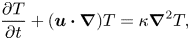 \begin{gather}\frac{\partial T}{\partial t} + (\boldsymbol{u} \boldsymbol{\cdot} \boldsymbol{\nabla})T= \kappa \boldsymbol{\nabla}^2 T, \end{gather}
where  $p(\boldsymbol {x},t)$ is the pressure, $T(\boldsymbol {x},t)$ is the temperature, and $\rho$, $\nu$, $g$,
$g$,  $\alpha$ and $\kappa$ are mass density, kinematic viscosity, acceleration due to gravity, a volumetric expansion coefficient and thermal diffusivity, respectively. Here $\boldsymbol {e}_{z}$ is a unit vector in the vertical direction. The velocity and temperature fields are supposed to be periodic in the horizontal ( $x$- and $y$-) directions, and the periods in the $x$- and $y$-directions are taken to be $L$.
$L$.
We suppose that the two horizontal walls are composed of porous media with constant-pressure plenum chambers underneath and overhead. The lower (or upper) wall and the associated plenum chamber are heated from below (or cooled from above). On the permeable wall surface the vertical velocity  $w$ is assumed to be proportional to the local pressure fluctuation $p'$ (Jiménez et al. Reference Jiménez, Uhlmann, Pinelli and Kawahara2001). The boundary conditions imposed on the walls are
 \begin{gather} u(z=0)=u(z=H)=0, \quad v(z=0)=v(z=H)=0,\end{gather}
 \begin{gather} w(z=0)=-\beta\frac{{p'(z=0)}}{\rho}, \quad w(z=H)=\beta\frac{{p'(z=H)}}{\rho}, \end{gather}
 \begin{gather} T(z=0)=\Delta T, \quad T(z=H)=0, \end{gather}
where  $\beta$ ( $\geqslant 0$) represents the property of permeability, and the impermeability conditions $w(z=0,H)=0$ are recovered for $\beta =0$, while $\beta \to \infty$ implies zero pressure fluctuations and an unconstrained vertical velocity. The flow situation observed in the thermal convection without horizontal walls (Calzavarini et al. Reference Calzavarini, Lohse, Toschi and Tripiccione2005) is intuitively similar to this limit, although not identical. Note that a zero net mass flux through the permeable wall is instantaneously ensured because the transpiration velocity is proportional to the pressure fluctuation with zero mean. We anticipate the no-slip and permeable conditions (2.4a,b) and (2.5a,b) on a realistic wall (see § 6 for the realistic configuration) with a large number of wall-normal through-holes connected to a constant-pressure plenum chamber underneath (or overhead). In such a permeable wall the fluid is expected to go in or out of the wall in the wall-normal direction through the holes, implying no wall-parallel velocity component on the wall. We investigate this isothermal, no-slip and permeable configuration so that we may have not only a thermal conduction layer but also a viscous layer of the wall-parallel velocity on the wall as in a usual no-slip case.
The proportionality coefficient  $\beta$ has the dimension of an inverse velocity, and thus $\beta U$ represents a dimensionless parameter determining the property of permeable walls if the buoyancy-induced terminal velocity $U=(g \alpha \Delta T H)^{1/2}$ is a proper velocity scale. If the proper velocity scale (say, $U_w$) is smaller than $U$ as in the subcritical permeable case discussed later (see (5.2) in § 5), then the permeable condition $\beta U=\mbox {const}$. ( ${=}\beta ' U_w$) to be employed here implies a more permeable wall of larger $\beta '$ ( ${=}(U/U_w)\beta$). Thermal convection between permeable walls is characterised in terms of the Rayleigh number $Ra$, the Prandtl number $Pr$ and the permeability $\beta U$, where
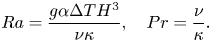 \begin{equation} Ra=\frac{g \alpha \Delta T H^3}{\nu \kappa}, \quad Pr=\frac{\nu}{\kappa}. \end{equation}
 The vertical heat flux from the bottom to the top wall is quantified by the Nusselt number  $Nu$ written as
 \begin{equation} Nu\equiv\left.-\frac{H}{\Delta T} \frac{\textrm{d} \langle T \rangle_{xyt}}{ \textrm{d} z} \right|_{z=0 }\equiv-\left.\frac{H}{\Delta T} \frac{\textrm{d} \langle T \rangle_{xyt}}{ \textrm{d} z} \right|_{z=H} {=1+\frac{H}{\kappa \Delta T} \langle wT \rangle_{xyzt}},\end{equation}
where  $\langle \cdot \rangle _{xyt}$ represents the average over the two horizontal directions and time, and $\langle \cdot \rangle _{xyzt}$ is the volume and time average. The rightmost equality is given by the volume and time average of the energy equation (2.3). Note that, since the walls are isothermal in the permeable and impermeable cases, the temperature fluctuation and so the convective heat flux $\langle Tw \rangle _{xyt}$ are null on the walls ( $z=0$, $H$) in any case. In the near-wall region, therefore, the conduction heat transfer dominates the convective one even in the permeable case.
The Boussinesq equations (2.1)–(2.3) are discretised by employing a spectral Galerkin method based on the Fourier series expansion in the periodic horizontal directions and the Chebyshev polynomial expansion in the vertical direction. The nonlinear terms are evaluated using a spectral collocation method. Aliasing errors are removed with the aid of the  $2/3$ rule for the Fourier transform and the $1/2$ rule for the Chebyshev transform. Time advancement is performed with the third-order Runge–Kutta scheme (or the second-order Adams–Bashforth scheme) for the nonlinear and buoyancy terms and the implicit Euler scheme (or the Crank–Nicolson scheme) for the diffusion terms in the permeable (or impermeable) case. The numerical procedure developed by Jiménez et al. (Reference Jiménez, Uhlmann, Pinelli and Kawahara2001) is applied to satisfy the permeable boundary conditions. In the permeable case the evaluation of the pressure is necessary for time marching of the evolution equation. A Poisson equation for the pressure is numerically solved with the boundary conditions
 \begin{equation} \frac{1}{\rho}\frac{\partial p'}{\partial z}\mp\frac{\beta}{\rho\Delta t}p'=\mp\frac{\beta}{\rho\Delta t}p'_{-} + \nu \nabla^2 w_{-} +g\alpha T \end{equation}
on the walls  $z=0$, $H$, where $\Delta t$ is a time increment and $(\cdot )_{-}$ denotes computed variables at the prior time step. These boundary conditions for the pressure have been given by the vertical component of the temporally discretised Navier–Stokes equation on the walls in conjunction with the permeable conditions (2.5a,b). In this paper, we shall present the results obtained from DNS for thermal convection in the impermeable case $\beta U=0$ at $Ra=10^6\text {--}10^{11}$ and in the permeable case $\beta U=3$ at $Ra=3\times 10^3\text {--}10^{10}$ for fixed Prandtl number $Pr=1$ and for fixed horizontal period $L/H=1$. Numerical parameters in the permeable simulations are given for the Prandtl number $Pr=1$ at $Ra=10^6$– $10^{10}$ in appendix A. The $Pr$ dependence is shown in appendix B. We have examined the dependence of heat transfer on the horizontal period in the range of $1\leqslant L/H\leqslant 4$ to confirm that the ultimate scaling $Nu\sim Ra^{1/2}$, to be shown in § 4, can also be achieved for smaller $\beta U$ in a wider periodic box of larger $L/H$.
3. Energy budget
In this section, we discuss the total energy budget in thermal convection between no-slip, permeable walls. By taking the volume and time average of an inner product of the Navier–Stokes equation (2.2) with the velocity  ${\boldsymbol {u}}$ and taking account of the boundary conditions (2.4a,b) and (2.5a,b), we obtain
 \begin{equation} g \alpha \langle w T \rangle_{xyzt}=\epsilon +\frac{1}{\beta H}\left( \left. {\left\langle w^{2} \right\rangle}_{xyt} \right|_{z=0}+ \left. {\left\langle w^{2} \right\rangle}_{xyt}\right|_{z=H} \right) +\frac{1}{2 H}{\left[ {\left\langle w^3 \right\rangle}_{xyt} \right]}^{z=H}_{z=0}, \end{equation}
where
 \begin{equation} \epsilon=\frac{\nu}{2}\left\langle\left(\frac{\partial u_i}{\partial x_j}+\frac{\partial u_j}{\partial x_i}\right)^2\right\rangle_{xyzt} \end{equation}
is a total energy dissipation rate per unit mass. The left-hand side of (3.1) represents buoyancy power (energy input), while the second and the third terms on the right-hand side denote pressure power on the permeable walls and outflow kinetic energy across the permeable walls, respectively. The pressure power on the permeable walls is strictly greater than zero, so that it is always an energy sink. Although its sign cannot be specified rigorously, we have confirmed numerically that the outflow kinetic energy across the permeable walls is also positive in the present DNS, implying that the kinetic energy flows out of the system across the permeable walls. It turns out that as in the impermeable case, thermal convection between the permeable walls is sustained only by the buoyancy power without any additional energy inputs. It has also been found numerically that the pressure power is comparable with the energy dissipation whereas the outflow kinetic energy is much less than the dissipation. The energy to be lost in the system via the permeable walls could be considered to be supplied to another system, i.e. the flow in porous media, to eventually dissipate therein.
The rightmost equality of (2.8) yields the relation among the buoyancy power, the Prandtl number, the Rayleigh number and the Nusselt number given by
 \begin{equation} {Pr^{-2}}Ra(Nu-1)=\frac{g \alpha \langle w T \rangle_{xyzt} }{ {{\nu}^3/H^4} }. \end{equation}
Substituting (3.3) into (3.1) and taking into account the flow symmetries, we arrive at
 \begin{equation} {Pr^{-2}}Ra(Nu-1)=\frac{\epsilon}{{\nu}^3/H^4} +\frac{2}{\beta ({\nu}/H)^3}\left. {\left\langle w^{2} \right\rangle}_{xyt} \right|_{z=0} -\frac{1}{({\nu}/H)^3}\left. {\left\langle w^3 \right\rangle}_{xyt} \right|_{z=0}. \end{equation}
Note that in the impermeable case, i.e. conventional RBC, the energy budget is given by
 \begin{equation} {Pr^{-2}}Ra(Nu-1)=\frac{\epsilon}{{\nu}^3/H^4}. \end{equation}
4. Scaling properties and turbulence structure
4.1.  $Nu$–$Ra$ scaling


Let us first discuss the scaling property of the Nusselt number  $Nu$ with the Rayleigh number
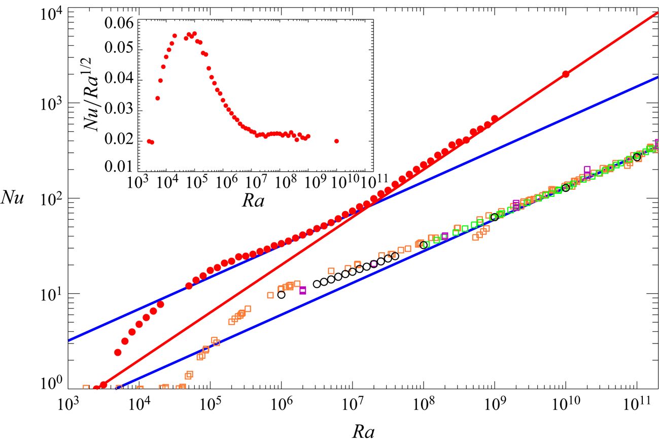
  $Ra$. Figure 1 shows $Nu$ as a function of $Ra$. It can be seen that the wall permeability leads to significant heat transfer enhancement over the entire $Ra$ range. In the impermeable case $\beta U=0$ the present DNS data in the horizontally periodic domain are in good agreement with the turbulent data obtained from the experiments (Chavanne et al. Reference Chavanne, Chilla, Chabaud, Castaing and Hebral2001; Niemela & Sreenivasan Reference Niemela and Sreenivasan2006) and the numerical simulation (Stevens et al. Reference Stevens, Verzicco and Lohse2010) performed in cylindrical containers. At high Rayleigh number $Ra\sim 10^{9}$– $10^{11}$, $Nu$ can be seen to scale with $Ra$ as $Nu\approx 0.06 Ra^{1/3}$, the prefactor and the exponent of which are nearly consistent with the well known turbulence scaling at much higher $Ra$ (see e.g. Urban, Musilova & Skrbek Reference Urban, Musilova and Skrbek2011; He et al. Reference He, Funfschilling, Nobach, Bodenschatz and Ahlers2012b; Iyer et al. Reference Iyer, Scheel, Scumacher and Sreenivasan2020; Doering Reference Doering2020). In the permeable case $\beta U=3$, on the other hand, the ultimate scaling $Nu\sim Ra^{1/2}$ can be observed at higher Rayleigh number $Ra\sim 10^{7}$– $10^{10}$, whereas the classical scaling $Nu\sim Ra^{1/3}$ is confirmed at lower Rayleigh number $Ra\sim 10^{6}$– $10^7$. It is worth noting that the scaling property of $Nu$ critically changes around $Ra\sim 10^{7}$ from $Nu\sim Ra^{1/3}$ to $Nu\sim Ra^{1/2}$ with increasing $Ra$.
$Ra$.
The Nusselt number  $Nu$ as a function of the Rayleigh number $Ra$. The open black and filled red circles, respectively, represent the present DNS data in the impermeable case $\beta U=0$ and permeable case $\beta U=3$ for the Prandtl number $Pr=1$. The orange and green squares denote the experimental data in a cylindrical cell, taken from Chavanne et al. (Reference Chavanne, Chilla, Chabaud, Castaing and Hebral2001) ( $Pr \geqslant 0.7$) and Niemela & Sreenivasan (Reference Niemela and Sreenivasan2006) ( $Pr \geqslant 0.69$), respectively. The purple squares stand for DNS data in a cylindrical cell, taken from Stevens et al. (Reference Stevens, Verzicco and Lohse2010) ( $Pr=0.7$). The red line represents the ultimate scaling $Nu=0.02 Ra^{1/2}$. The upper and lower blue lines indicate the classical scaling, $Nu=0.37 Ra^{1/3}$ and $Nu=0.06 Ra^{1/3}$, respectively. The inset shows $Nu$ compensated by $Ra^{1/2}$ in the permeable case.
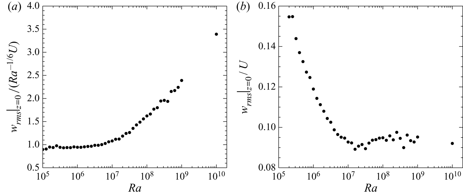
This critical transition in the permeable case can also be confirmed undoubtedly for the root mean square (RMS) vertical velocity  $w_{{rms}}=\langle w^{2} \rangle _{xyt}^{1/2}$ on the wall as shown in figure 2. In the subcritical $Ra$ range $10^{6}\lesssim Ra\lesssim 10^{7}$, the wall-normal transpiration velocity is weak in the sense that it is of the order of $Ra^{-1/6} U$ (see figure 2a), corresponding to the vertical velocity scale in the near-wall region of RBC for $Pr\sim 1$, i.e. the impermeable case, in which the classical scaling $Nu \sim Ra^{1/3}$ has been observed. In the supercritical $Ra$ range $10^{7}\lesssim Ra\lesssim 10^{10}$, on the other hand, the RMS velocity on the wall is significantly strong in the sense that it scales with the buoyancy-induced terminal velocity $U$ (see figure 2b). In § 5, for the case of $Pr\sim 1$, the near-wall vertical velocity scale $Ra^{-1/6} U$ will be related with the classical scaling $Nu \sim Ra^{1/3}$, and the relevance of the vertical velocity scale $U$ to the ultimate scaling $Nu\sim Ra^{1/2}$ will also be discussed.
The RMS vertical velocity on the wall  $z=0$ normalised by (a) $Ra^{-1/6}U$ and (b) $U$ in the permeable case $\beta U=3$.
We would like to stress that the ultimate heat transfer is not simplistically a consequence of just the wall permeability. As will be shown later in this section, the wall permeability can trigger a critical change in convection states, consequently leading to the ultimate scaling  $Nu\sim Ra^{1/2}$.
4.2. Mean temperature
Next we differentiate mean temperature profiles between the supercritical permeable case  $\beta U=3$ at $Ra\gtrsim 10^7$ and the impermeable case $\beta U=0$. Figure 3 presents the mean temperature profiles in the impermeable and permeable cases. In the impermeable case, at higher $Ra$ the profile becomes flatter in the bulk region, while the near-wall temperature gradient becomes steeper. In short the mean temperature profile $\langle T \rangle _{xyt}/\Delta T$ cannot scale with $z/H$. The behaviour of the mean temperature in the subcritical case at $Ra\lesssim 10^7$ is similar to that in the impermeable case. In contrast to the impermeable case and the subcritical case, the mean temperature profile in the bulk region seems to scale with $\Delta T$ as a function of $z/H$ in the supercritical permeable case at $Ra\gtrsim 10^7$, and there remains a finite value of the temperature gradient, i.e. the order of $\Delta T/H$, therein even at high $Ra$. This contrast should be a crucial consequence of the ultimate heat transfer as will be discussed in § 5.
Mean temperature profiles as a function of (a,b)  $z/H$ and (c,d) $z/\delta$; (a,c) the impermeable case $\beta U=0$ and (b,d) the permeable case $\beta U=3$.
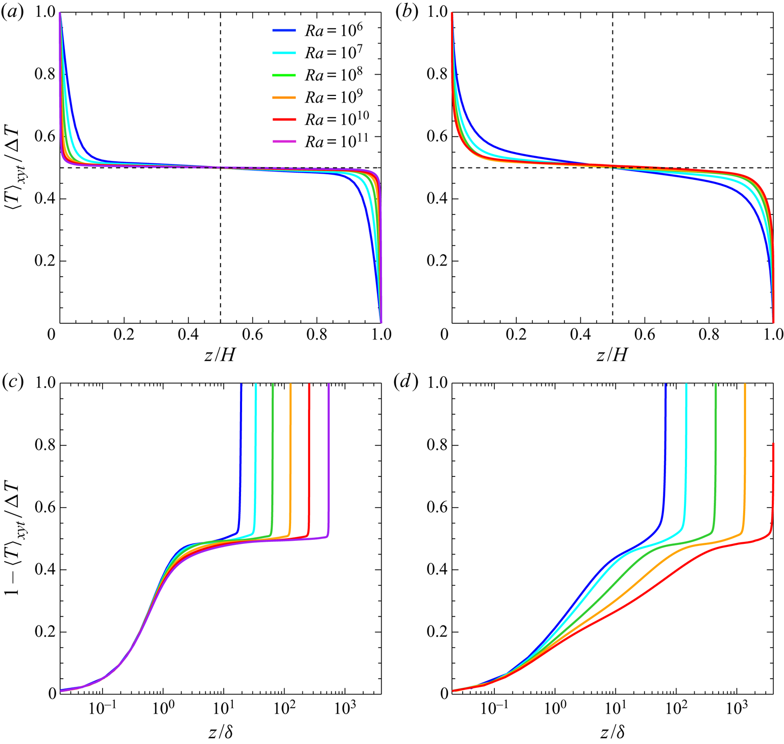
In the permeable case with isothermal wall boundaries, different from the thermal convection without horizontal walls (Calzavarini et al. Reference Calzavarini, Lohse, Toschi and Tripiccione2005; Pawar & Arakeri Reference Pawar and Arakeri2016), there exists a thermal conduction layer on the wall, where heat transfer by conduction dominates over that by convection. In figure 3(c,d) are shown the mean temperature profiles  $1-\langle T \rangle _{xyt}/\Delta T$ as a function of $z/\delta$, where $\delta$ is the thickness of a thermal conduction layer defined as
 \begin{equation} \delta\equiv-\Delta T{\left( \left. \frac{\textrm{d}{\left\langle T \right\rangle}_{xyt}}{\textrm{d}z} \right|_{z=0} \right)}^{-1}=\frac{H}{2 Nu}. \end{equation}
All the profiles in the impermeable case collapse onto a single curve in the thermal conduction layer  $z/{\delta }\lesssim 1$. It is also the case in the permeable case; however, the thermal conduction cannot be dominant around $z/\delta \sim 1$ where the convection is also important. The large difference of the temperature profiles at $z/\delta \gtrsim 1$ in the supercritical permeable case at $Ra\gtrsim 10^7$ implies its reasonable scaling with $z/H$, shown in figure 3(b).
4.3. RMS velocity and temperature
As mentioned before, the vertical velocity fluctuation on the permeable walls scales with  $Ra^{-1/6} U$ at subcritical Rayleigh number $Ra\lesssim 10^7$. In the impermeable case (in addition to the subcritical permeable case) the near-wall RMS vertical velocity $w_{rms}=\langle w^{2} \rangle _{xyt}^{1/2}$ also scales with $Ra^{-1/6} U$ as a function of $z/\delta$ (see figure 4a). However, the vertical velocity fluctuation in the supercritical case at $Ra\gtrsim 10^7$ exhibits quite distinct behaviour from that in the impermeable and subcritical cases (see figure 4b).
The RMS vertical velocity normalised by  $Ra^{-1/6} U$ as a function of $z/\delta$; (a) the impermeable case $\beta U=0$ and (b) the permeable case $\beta U=3$.
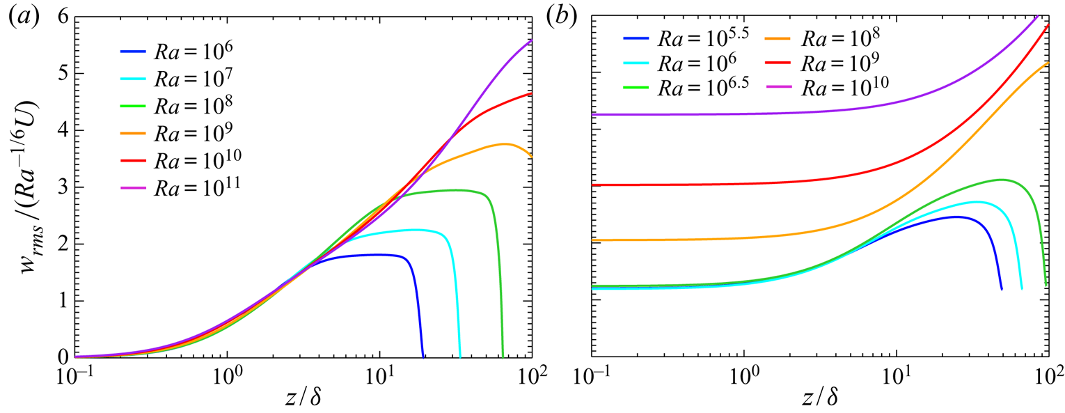
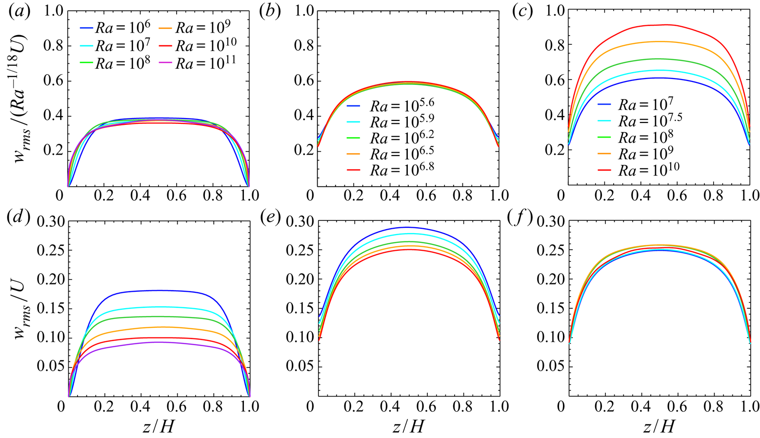
Figure 5(a–c) and figure 5(d–f) show the RMS vertical velocity normalised by the velocity scale  $Ra^{-1/18} U$ and the buoyancy-induced terminal velocity $U$, respectively. In the impermeable case at $10^{6}\leqslant Ra\leqslant 10^{11}$ and the subcritical permeable case at $10^{5.6}\leqslant Ra\leqslant 10^{6.8}$, the RMS vertical velocity in the bulk region is seen to scale with $Ra^{-1/18} U$ corresponding to the vertical velocity scale in the bulk region of RBC for $Pr\sim 1$ (figure 5a,b), and thus it decreases relatively with respect to $U$ as $Ra$ increases (figure 5d,e). In the supercritical permeable case at $10^{7}\leqslant Ra\leqslant 10^{10}$, on the other hand, the velocity fluctuation in the bulk is found to scale with $U$ (figure 5f). The near-wall gradient of $w_{rms}$ with respect to $z/H$ in figure 5 is steeper at higher $Ra$ in the impermeable and the subcritical permeable cases, but the same is not true of the supercritical permeable case. Although $w_{rms}$ is not null on the permeable walls as already shown in figure 2, the ratio of near-wall $w_{rms}$ to bulk $w_{rms}$ should be of the order of $Ra^{-1/9}$ in the subcritical case, implying that the near-wall vertical velocity fluctuation becomes smaller than that in the bulk region at higher $Ra$ (see figure 5b). The vertical RMS velocities $w_{ rms}/U$ as a function of $z/H$ are almost independent of the Rayleigh number $Ra$ in the whole region of the supercritical permeable case. Note that near the walls, the RMS velocity is suppressed due to the presence of the walls even in the supercritical permeable case exhibiting the ultimate scaling $Nu\sim Ra^{1/2}$. Needless to say, such suppression of the vertical velocity has not been observed in the ultimate heat transfer in wall-less ‘homogeneous’ thermal convection (Calzavarini et al. Reference Calzavarini, Lohse, Toschi and Tripiccione2005; Pawar & Arakeri Reference Pawar and Arakeri2016).
The RMS vertical velocity normalised by (a–c)  $Ra^{-1/18} U$ and (d–f) $U$; (a,d) the impermeable case $\beta U=0$, (b,e) the subcritical permeable case $\beta U=3$ at $10^{5.6}\leqslant Ra\leqslant 10^{6.8}$ and (c,f) the supercritical permeable case $\beta U=3$ at $10^{7}\leqslant Ra\leqslant 10^{10}$.
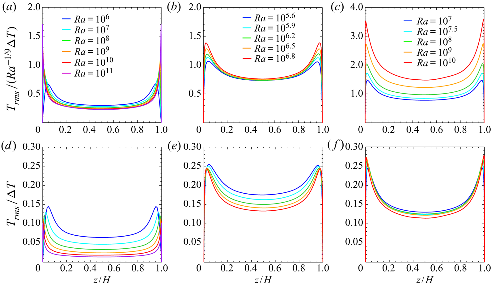
The RMS temperature  $T_{rms}=\langle (T-{\langle T \rangle }_{xyt})^{2} \rangle _{xyt}^{1/2}$ normalised by the temperature scale $Ra^{-1/9} \Delta T$ and the temperature difference $\Delta T$ between the walls is shown in figure 6(a–c) and figure 6(d–f), respectively. In the bulk region of the impermeable and subcritical permeable cases, the RMS temperature is seen to scale with $Ra^{-1/9}\Delta T$ (figure 6a,b), and so it decreases as $Ra$ increases. On the other hand, the temperature fluctuation in the supercritical permeable case is found to scale with $\Delta T$ (figure 6f). This remarkable difference in the scalings of the temperature fluctuation originates from the scaling difference in the mean temperature (cf. figure 3). In the supercritical permeable case the vertical fluid motion across the sustaining mean temperature difference of $O(\Delta T)$ in the bulk region can induce the temperature fluctuation of $O(\Delta T)$ even at higher $Ra$, but in the impermeable and the subcritical cases the vanishing mean temperature difference means small temperature fluctuations.
The RMS temperature normalised by (a–c)  $Ra^{-1/9} \Delta T$ and (d–f) $\Delta T$; (a,d) the impermeable case $\beta U=0$, (b,e) the subcritical permeable case $\beta U=3$ at $10^{5.6}\leqslant Ra\leqslant 10^{6.8}$ and (c,f) the supercritical permeable case $\beta U=3$ at $10^{7}\leqslant Ra\leqslant 10^{10}$.
In § 5 we shall discuss the different scaling properties of the RMS vertical velocity with  $Ra^{-1/18} U$ and $U$ as well as the difference in scaling of the temperature fluctuation with $Ra^{-1/9} \Delta T$ and $\Delta T$.
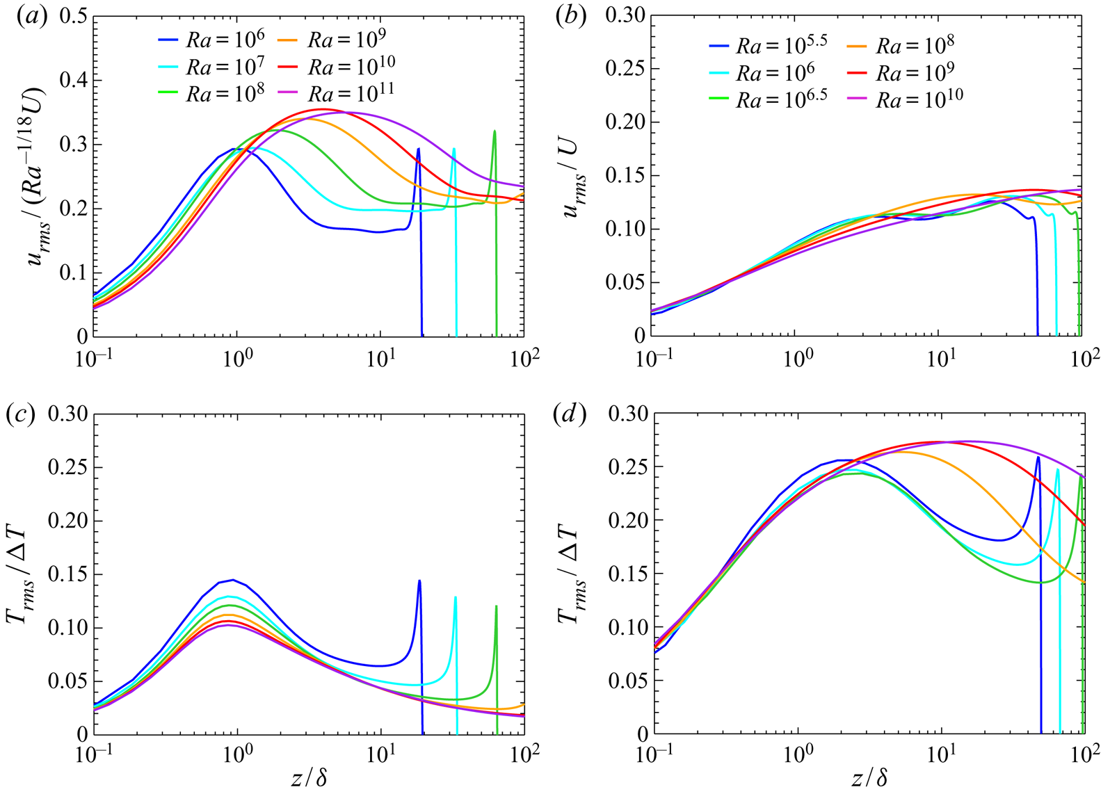
In figure 7 are shown the near-wall profiles of the wall-parallel (horizontal) RMS velocity  $u_{rms}=\langle u^{2} \rangle _{xyt}^{1/2}$ and the RMS temperature $T_{rms}$. As can be seen from the figures, in the impermeable case and the supercritical permeable case, the near-wall horizontal velocity fluctuation could scale with the bulk velocity scale $U_b$ as a function of $z/\delta$ at higher $Ra$. Note that as shown in figure 5(a,f), in the impermeable case $U_b\sim Ra^{-1/18}U$ (see also (5.9) in § 5) whereas in the supercritical permeable case $U_b\sim U$ (see also (5.11) in § 5). At higher $Ra$ the near-wall temperature fluctuation might scale with $\Delta T$ as a function of $z/\delta$ in any case. These results imply that in the near-wall region of both the impermeable case and the supercritical permeable case, the amplitude of turbulence velocity and temperature fluctuations is determined by the bulk velocity scale $U_b$ and temperature difference $\Delta T$, respectively. As will be discussed in § 5, the key to the achievement of the ultimate heat transfer in the supercritical permeable case should be the difference in scaling of $U_b$ rather than transition to turbulence in boundary-layer flow, which might be expected in conventional RBC at extremely high $Ra$ (Kraichnan Reference Kraichnan1962; Grossmann & Lohse Reference Grossmann and Lohse2011).
The near-wall RMS velocity and temperature as a function of  $z/\delta$. (a,b) The RMS horizontal velocity normalised by $Ra^{-1/18}U$ and $U$ and (c,d) the RMS temperature normalised by $\Delta T$; (a,c) the impermeable case $\beta U=0$ and (b,d) the permeable case $\beta U=3$.
4.4. Turbulent thermal and flow structures
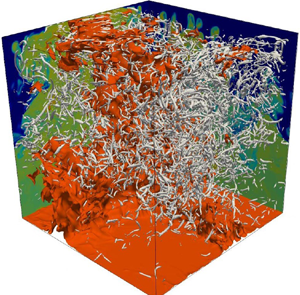
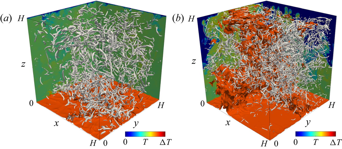
Let us now look into turbulence structure of thermal convection. Figure 8 visualises the instantaneous thermal and vortical structures in the impermeable and supercritical permeable case at  $Ra=10^{9}$. The high-temperature thermal plumes are represented by the isotherms $T/\Delta T=0.7$, while the small-scale vortical structures are identified in terms of the positive isosurfaces of the second invariant of the velocity gradient tensor
 \begin{equation} Q=-\frac{1}{2} \frac{\partial u_i}{\partial x_j} \frac{\partial u_j}{\partial x_i}. \end{equation}
In the impermeable case the small-scale hot plumes are confined to the near-wall region. In contrast, high-temperature plumes of a remarkably large horizontal length scale fully extend from the bottom wall to the top wall through the bulk in the supercritical permeable case, so that heat transfer is highly enhanced. Recently, such promotion of large-scale circulation has been reported for the convective turbulence, which exhibits the ultimate scaling  $Nu\sim Pr^{1/2}Ra^{1/2}$, in the radiatively driven convection (Lepot et al. Reference Lepot, Aumaître and Gallet2018) and in the thermal convection between rough walls (Tummers & Steunebrink Reference Tummers and Steunebrink2019). Although the intensity and the size of small-scale tubular vortices playing a role in energy dissipation are different between the impermeable and the supercritical permeable cases, their spatial structure is more or less the same.
Instantaneous thermal and vortical structures in (a) the impermeable case  $\beta U=0$ and (b) the supercritical permeable case $\beta U=3$ at $Ra=10^{9}$. The orange and grey objects, respectively, represent the isosurfaces of the temperature $T/\Delta T =0.7$ and of the second invariant of the velocity gradient tensor, (a) $Q/(\nu ^{2}/H^{4})=8\times 10^{10}$ and (b) $Q/(\nu ^{2}/H^{4})=4.8\times 10^{11}$. The colour indicates the temperature distribution on the planes $x=0$ and $y=H$.
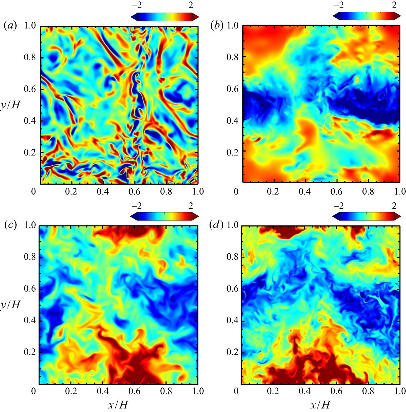
In figure 9 are shown snapshots of the convective heat flux  $wT$ (which is proportional to local buoyancy power) on the horizontal plane $z/\delta \approx 1$ in the conduction layer and on the midplane $z/H=1/2$. Note that in these panels, $wT$ is normalised so that its mean and standard deviation may be zero and unity, respectively, in each plane of the impermeable and the supercritical permeable cases. The spatial distribution near the wall differs greatly between the impermeable and supercritical permeable cases (figure 9a,b). The near-wall small-scale structures, corresponding to thermal plumes, can be observed in the impermeable case, while the large-scale structure, which is part of the fully extended large-scale plume, appears even in the vicinity of the wall in the supercritical case. On the midplane there is no significant difference between the impermeable and supercritical cases (figure 9c,d). In the bulk region the heat transfer is dominated by large-scale convection, regardless of the difference in the near-wall dominant thermal structures.
The instantaneous convection heat flux  $wT$ on (a,b) the near-wall plane $z/\delta \approx 1$ and (c,d) the midplane $z/H=1/2$ at $Ra=10^{9}$; (a,c) the impermeable case $\beta U=0$ and (b,d) the supercritical permeable case $\beta U=3$. The heat flux $wT$ on the horizontal plane is normalised so that its mean and standard deviation may be zero and unity, respectively.
4.5. Energy production by buoyancy
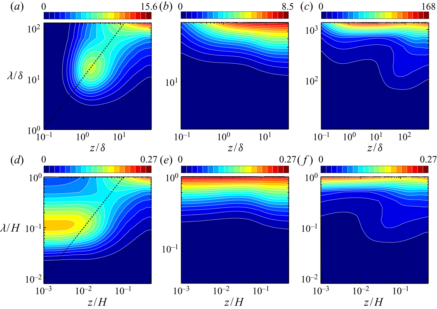
In figure 10 we show the one-dimensional premultiplied buoyancy-power spectra  $k_{y}\sum _{k_{x}}\hat {P}(k_{x},k_{y},z)$ as a function of the distance to the wall, $z$, and the wavelength in the horizontal ( $y$-) direction, $\lambda =2{\rm \pi} /k_{y}$. The buoyancy-power spectra $\hat {P}(k_x,k_y,z)$ is given by
 \begin{equation} \hat{P}(k_x,k_y,z)=g \alpha {{Re}} \left[ \langle \hat{w}\hat{T}^{\dagger}ger \rangle_{t} \right], \end{equation}
where  $\widehat {(\cdot )}$ represents the Fourier coefficients, $(k_x, k_y)$ are the wavenumbers in the horizontal ( $x$- and $y$-) directions, ${\dagger}ger$ denotes the complex conjugate and $\langle \cdot \rangle _{t}$ is the time average. The lateral and longitudinal axes of the figures are normalised by the conduction layer thickness $\delta$ or the wall distance $H$. Here $\hat {P}$ denotes the spectrum of the energy input by buoyancy, and it is also relevant to the spectrum of the convective heat flux shown in figure 9. In the impermeable case we can see significant buoyancy power at small scales in the vicinity of the wall, $z/\delta \sim 10^0$, leading to the near-wall thermal plumes (figure 9a), in addition to greater buoyancy power corresponding to the large-scale convection in the bulk region. The near-wall heat flux determined by the marginal instability of the thermal conduction layer gives us the scaling $Nu\sim Ra^{1/3}$ widely observed in turbulent RBC (Malkus Reference Malkus1954). The dashed lines in figure 10(a,d) stand for $\lambda =10 z$. The spectral ridge is on this line, implying that the energy-inputted horizontal scale is proportional to the distance to the wall. This observation suggests that the convective heat flux exhibits hierarchical self-similar structure near the wall. In the subcritical permeable case at $Ra=10^{6}$ (figure 10b,e), the Rayleigh number is too low for the small-scale plumes of $\lambda \ll L(=H)$ to appear in the near-wall region. In the supercritical case (figure 10c,f) the spectral peak is located at the large horizontal scale $\lambda /\delta \sim 10^3$ ( $\lambda /H\sim 10^0$) in the near-wall region $z/\delta \sim 10^0$ roughly consistent with the wall-normal position of the spectral peak of the small-scale thermal plumes in the impermeable case (figure 10a), suggesting that the large-horizontal-scale plume is generated in the near-wall region by buoyancy to fully extend from there to the other wall as observed in figure 8(b). This near-wall large-scale energy input corresponds to the large-scale convective heat flux shown in figure 9(b). As will be discussed in § 5, the ultimate heat transfer $Nu\sim Ra^{1/2}$ can be attributed to the generation of this long-wavelength (and so intense) thermal mode near the wall. In the bulk region, apart from the walls, the energy is inputted at the large horizontal length scale in all the impermeable and permeable cases. We note, however, that just in the supercritical case the energy to be inputted at the large horizontal scale in the bulk is smaller than that in the near-wall region (figure 10c).
One-dimensional premultiplied buoyancy-power spectra  $k_{y}\sum _{k_{x}}\hat {P}(k_{x},k_{y},z)$ as a function of the wavelength $\lambda =2{\rm \pi} /k_y$ in the horizontal ( $y$-) direction and the distance to the bottom wall, $z$. (a–c) The spectra normalised with $Ra\nu ^3/H^5$ as a function of $\lambda /\delta$ and $z/\delta$, (d–f) the spectra normalised with $g\alpha \langle wT\rangle _{xyt}/H$ as a function of $\lambda /H$ and $z/H$; (a,d) the impermeable case $\beta U=0$ at $Ra=10^{9}$, (b,e) the subcritical permeable case $\beta U=3$ at $Ra=10^{6}$, (c,f) the supercritical permeable case $\beta U=3$ at $Ra=10^{9}$. In panel (d) $g\alpha \langle wT\rangle _{xyt}/(\nu ^3/H^4)=3.7\times 10^{8}$– $6.3\times 10^{10}$, in panel (e) $g\alpha \langle wT\rangle _{xyt}/(\nu ^3/H^4)=5.6\times 10^6$– $3.3\times 10^7$, and in panel (f) $g\alpha \langle wT\rangle _{xyt}/(\nu ^3/H^4)=6.2\times 10^{11}$– $6.8\times 10^{11}$. The dashed lines indicate $\lambda =10z$.
5. Physical interpretation of scaling laws
Here we shall discuss the physical mechanisms of the classical scaling  $Nu\sim Ra^{1/3}$ and the ultimate scaling $Nu\sim Pr^{1/2}Ra^{1/2}$ in turbulent thermal convection between impermeable and permeable walls. In the present study the Prandtl number has been set to unity, i.e. $Pr=1$, and thus in this section we assume that $Pr\sim 1$ (or $\nu \sim \kappa$).
5.1. Impermeable and subcritical permeable cases
Let us start with the thermal convection in the impermeable case and the subcritical permeable case, where the temperature profile is flatter in the bulk region at higher  $Ra$ and temperature variation is confined to the thermal conduction layer of the thickness of $O(\delta )$ (see figure 3a,b). The vertical velocity is strictly zero on the impermeable walls. In the subcritical permeable case, as shown in figures 2 and 4, transpiration has not been activated in the near-wall region although the walls are permeable. In both the impermeable and subcritical cases, the near-wall vertical velocity scale $U_w$ is estimated to be $\kappa /\delta$ from the near-wall comparability of thermal conduction to convective heat transfer, $\kappa \Delta T/\delta \sim \Delta T U_w$, being small in comparison to the velocity scale $U_b$ in the bulk region. We now suppose that in the near-wall viscous layer with thickness $\delta '$ of $O(\delta )$ and with a temperature difference of $O(\Delta T)$, where the vertical velocity is small, the effect of viscosity is also significant. In the vertical component of the Navier–Stokes equation (2.2), the viscous term can be comparable with the advection term and the buoyancy term (driving force of the flow), that is,
 \begin{equation} \nu \frac{U_w}{\delta'^2} \sim \frac{U_w^2}{\delta'} \sim g \alpha \Delta T, \end{equation}
in the near-wall viscous region. The balance (5.1) between the viscous, the advection and the buoyancy terms in the equation of motion determines the near-wall velocity and the length scales as
 \begin{gather} U_w \sim Ra^{1/3}Pr^{-1/3}\nu/H \sim Ra^{-1/6}Pr^{1/6}U \sim Ra^{-1/6}U, \end{gather}
 \begin{gather}\delta' \sim Ra^{-1/3}Pr^{1/3}H \sim Ra^{-1/3}H \end{gather}
(recall that  $U=(g\alpha \Delta TH)^{1/2}{\sim Ra^{1/2}Pr^{-1/2}\nu /H}$ and $H$ are the buoyancy-induced terminal velocity and the wall distance, respectively). In (5.2) and (5.3), the leftmost equality has been given by solving (5.1) while the rightmost one holds for $Pr\sim 1$. In the present DNS we have confirmed that the vertical velocity near the impermeable and subcritical permeable walls actually scales with $Ra^{-1/6}U$ (see figures 2a and 4). Since $\delta '\sim \delta$, and thus the definition (4.1) of the thermal conduction layer thickness implies that $\delta '\sim H/(2Nu)$, (5.3) suggests the scaling law
 \begin{equation} Nu\sim Ra^{1/3}, \end{equation}
which has been observed in RBC (i.e. the impermeable case) as well as in the subcritical permeable case (see figure 1). The scaling law  $Nu\sim Ra^{1/3}$ has already been given by the several arguments on similarity (Priestley Reference Priestley1954), the marginal instability (Malkus Reference Malkus1954) and the bulk contribution to energy and scalar dissipation (Grossmann & Lohse Reference Grossmann and Lohse2000).
In the bulk region of the impermeable and the subcritical cases, where the effects of viscosity or thermal conduction are no longer significant, the characteristic thermal (and flow) length scale is  $H$ instead of $\delta$ (and $\delta '$), and the temperature difference with respect to the height difference of $O(H)$ and the vertical velocity scale are supposed to be $\Delta T'$ and $U_b$, respectively. In this region the advection and the buoyancy terms balance each other out in the Navier–Stokes equation as
 \begin{equation} \frac{U_b^2}{H} \sim g \alpha \Delta T'. \end{equation}
Rewriting the Nusselt number (2.8) as
 \begin{equation} Nu=\frac{\langle wT \rangle_{xyt}-\kappa\,\textrm{d} \langle T \rangle_{xyt}/\textrm{d} z}{\kappa\Delta T/H} \end{equation}
and taking into consideration the dominance of convective heat transfer in the bulk and the scaling (5.4), we have
 \begin{equation} {Nu\sim\frac{\langle wT \rangle_{xyt}}{\kappa\Delta T/H}\sim} \frac{U_b \Delta T'}{\kappa \Delta T / H} \sim Ra^{1/3}. \end{equation}
Solving equations (5.5) and (5.7) we have the bulk temperature difference and velocity scale as
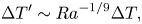 \begin{gather} \Delta T' \sim Ra^{-1/9} \Delta T, \end{gather}
 \begin{gather}U_b \sim Ra^{4/9}Pr^{-2/3}\nu/H \sim Ra^{-1/18}Pr^{-1/6} U \sim Ra^{-1/18} U. \end{gather}
The leftmost equality in (5.9) means that the Reynolds number for thermal convection,  $Re=\langle w^2\rangle _{xyzt}^{1/2}H/\nu$, is of the order of $Ra^{4/9}Pr^{-2/3}$, being consistent with the scaling of Grossmann & Lohse (Reference Grossmann and Lohse2000) based on the energy and scalar dissipation in the bulk region. It has been confirmed that the vertical velocity and the temperature fluctuation really scale with $Ra^{-1/18}U$ and $Ra^{-1/9} \Delta T$, respectively, in the bulk region of the impermeable and subcritical permeable cases (see figures 5a,b, 6a,b and appendix B).
5.2. Supercritical permeable case
Next we consider the thermal convection between the supercritical permeable walls. In this case intense vertical transpiration is induced even in the vicinity of the wall in contrast to the impermeable and the subcritical cases (see figure 2). Although the thermal conduction layer still exists on the wall, there is no near-wall layer of significant reduction in the vertical velocity, suggesting that the effect of the viscosity on the vertical velocity is negligible anywhere in comparison to the advection effect. The vertical motion should exhibit the length scale comparable with  $H$ (see figure 8b), and the corresponding temperature difference is of the order of $\Delta T$ even in the bulk region (recall the temperature gradient of $O(\Delta T/H)$ in figure 3b and the temperature fluctuation of $O(\Delta T)$ in figure 6f). Therefore, the balance of the advection term with the buoyancy term (the driving force) in the Navier–Stokes equation, (2.2), gives us
 \begin{equation} \frac{U_b^{2}}{H}\sim g\alpha\Delta T, \end{equation}
leading to
 \begin{equation} U_b \sim U {\sim Ra^{1/2}Pr^{-1/2}\nu/H}. \end{equation}
Equation (5.11) means that  $Re\sim Ra^{1/2}Pr^{-1/2}$, being consistent with the ultimate scaling of the Reynolds number. This scaling has been confirmed in the supercritical permeable case of the present DNS (see figures 5a,b and appendix B). The comparability between the energy dissipation (the first term in the right-hand side) and the pressure power (the second term) in the energy budget (3.4),
 \begin{equation} {\frac{\epsilon}{\nu^3/H^4} \sim \frac{U^3}{(\nu/H)^3}}, \end{equation}
suggests the Taylor dissipation law (energy dissipation independent of  $\nu$),
 \begin{equation} \epsilon\sim \frac{U^3}{H}, \end{equation}
where we have taken account of  $\langle w^2\rangle _{xyt}|_{z=0}\sim U^2$ and $\beta \sim U^{-1}$. The balance of the buoyancy power (the left-hand side) with the dissipation (and the pressure power) in (3.4) then yields
 \begin{equation} {Pr^{-2}RaNu\sim \frac{U^3}{(\nu/H)^3}}. \end{equation}
Equations (5.11) and (5.14) provide us with the ultimate scaling
 \begin{equation} Nu\sim Pr^{1/2}Ra^{1/2} \sim Ra^{1/2}. \end{equation}
Alternatively, it follows from (5.6) at  $z/\delta \gg 1$ and (5.11) that
 \begin{equation} Nu {\sim\frac{\langle wT \rangle_{xyt}}{\kappa\Delta T/H}} \sim\frac{U_b \Delta T}{\kappa \Delta T/H} \sim Pr^{1/2}Ra^{1/2} \sim Ra^{1/2}. \end{equation}
The ultimate scaling  $Nu\sim Ra^{1/2}$ has been suggested by Spiegel (Reference Spiegel1963), and its logarithmic correction with turbulent boundary layers has been given by Kraichnan (Reference Kraichnan1962) and Grossmann & Lohse (Reference Grossmann and Lohse2011) at extremely high $Ra$. In conventional RBC, it is still an open question whether or not the ultimate scaling (or the one with the logarithmic correction) can be observed (Ahlers et al. Reference Ahlers, He, Funfschilling and Bodenschatz2012; He et al. Reference He, Funfschilling, Bodenschatz and Ahlers2012a; Urban et al. Reference Urban, Hanzelka, Kralik, Musilova, Srnka and Skrbek2012; He et al. Reference He, Funfschilling, Nobach, Bodenschatz and Ahlers2013; Skrbek & Urban Reference Skrbek and Urban2015; Doering Reference Doering2020; Iyer et al. Reference Iyer, Scheel, Scumacher and Sreenivasan2020). In the present DNS of the supercritical permeable case, the vertical velocity has been seen to actually scale with $U$ in the whole region (see figure 5f), and it has been confirmed that $Nu\sim Ra^{1/2}$ at $Ra\gtrsim 10^7$ (see figure 1).
5.3. Linear instability on permeable wall
In the above discussions we have considered the difference in the vertical length scale of thermal convection,  $\delta$ and $H$, between the impermeable (and subcritical permeable) case and the supercritical permeable case and its crucial consequences on the scaling properties of heat transfer. The key to the difference in the vertical length scale is the excitation of transpiration in the near-wall region of the permeable wall. As suggested in figure 10, there should be different convection modes of the instabilities in a thermal conduction layer, one of which is the small-scale thermal plume in the impermeable (and subcritical permeable) case, and the other of which is the large-scale plume extending to the other wall in the supercritical permeable case. The excitation of the near-wall transpiration velocity on the permeable wall could be attributed to the different length of convection instability from that on the impermeable wall. In order to identify the different length of the instability, we have performed the linear stability analysis of a conduction state between the impermeable and permeable walls by conducting DNS in conjunction with the Arnoldi iteration, that is a Krylov-subspace method to compute eigenvalues in subspace without any full matrix construction. Although the global onset of thermal convection in the conduction state is distinct from the local one in the thermal conduction layer of turbulent convection, we could expect their qualitative similarity.
Figure 11 presents the onset Rayleigh number of thermal convection between impermeable and permeable walls. In the impermeable case (black symbols) we confirm the known lowest value  $Ra_c=1708$ for $\lambda /H=2{\rm \pi} /3.117=2.02$ (see Reid & Harris Reference Reid and Harris1958). In the permeable case, on the other hand, much larger-scale thermal convection can arise from the instability (colour lines with symbols). If such a larger-horizontal-scale thermal plume appears in the thermal conduction layer of convective turbulence, then the plume should also possess a larger vertical length scale to induce the significant vertical velocity. Actually the large-horizontal-scale thermal plume has been observed to extend from the near-wall region to the other wall in turbulent convection on the supercritical permeable walls (see figures 8b and 9b). The critical transition to the ultimate heat transfer observed in figures 1 and 2 could be a consequence of the exchange of near-wall unstable convection modes on the permeable wall, although the critical values of $Ra$ are quantitatively distinct between figure 1 (or figure 2) and figure 11, depending on the local and the global onset of convection.
The critical Rayleigh number  $Ra_c$ of the onset of two-dimensional thermal convection between impermeable and permeable walls as a function of the horizontal wavelength $\lambda$. The black symbols denote the impermeable case $\beta U=0$. The lines with the colour symbols represent the permeable case: blue, $\beta U=0.1$; cyan, $\beta U=0.5$; green, $\beta U=1$; orange, $\beta U=2$; red, $\beta U=3$; purple, $\beta U=4$. The black curve stands for the analytical marginal stability relation given by Prosperetti (Reference Prosperetti2011) for RBC (i.e. the impermeable case).

It is known that the installation of roughness elements on the wall yields the ultimate scaling in the limited range of  $Ra$ where the thickness of a thermal conduction layer is comparable with the size of the elements (Toppaladoddi et al. Reference Toppaladoddi, Succi and Wettlaufer2017; Zhu et al. Reference Zhu, Stevens, Verzicco and Lohse2017, Reference Zhu, Stevens, Shishkina, Verzicco and Lohse2019; MacDonald et al. Reference MacDonald, Hutchins, Lohse and Chung2019; Tummers & Steunebrink Reference Tummers and Steunebrink2019). Surface roughness of a comparable size can promote near-wall flow instability generating turbulence in the conduction layer to enhance a wall heat flux, so that the ultimate scaling could be achieved. In the supercritical permeable case the wall transpiration is induced by the instability on the permeable walls as in the case of surface roughness to significantly enhance large-scale turbulence leading to the ultimate heat transfer. In contrast with the roughness case, there should not be the limited range of $Ra$ for the ultimate heat transfer in the supercritical permeable case because no specific length scale, such as roughness elements, is on the permeable walls.
In DNS of the permeable case we have increased the horizontal period  $L$ in the range of $1\leqslant L/H\leqslant 4$ and have observed stronger convection in a wider periodic box of larger $L/H$ for $\beta U=3$. We have fitted the ultimate scaling law $Nu=c Ra^{1/2}$ (or $Re=c' Ra^{1/2}$) to the numerical data to estimate the prefactor $c$ (or $c'$) as $c=0.022$ (or $c'=0.23$) for $L/H=1$, $c=0.065$ (or $c'=0.35$) for $L/H=2$ and $c=0.17$ (or $c'=0.52$) for $L/H=4$, respectively. This intensification would be because longer-wavelength convection is more significant as a result of the convection instability (see figure 11). Smaller $\beta U\sim 10^{-1}$ would, however, lead to an optimal length scale of convection and thus no significant dependence of convective turbulence on the horizontal domain size.
6. Summary and outlook
We have performed the three-dimensional DNS of turbulent thermal convection between horizontal no-slip, permeable walls with a distance  $H$ and a constant temperature difference $\Delta T$. On the no-slip wall surfaces $z=0$, $H$, the vertical transpiration velocity has been assumed to be proportional to the local pressure fluctuation (Jiménez et al. Reference Jiménez, Uhlmann, Pinelli and Kawahara2001), i.e. $w=-\beta p'/\rho$, $+\beta p'/\rho$ mimicking a Darcy-type permeable wall (Batchelor Reference Batchelor1967, pp. 223–224). A zero net mass flux through the permeable wall is instantaneously ensured, and convective turbulence is driven only by buoyancy without any additional energy inputs. The permeability parameter is set to $\beta U=0$ (an impermeable case) and $\beta U=3$ (a permeable case) where $U=(g\alpha {\rm \Delta} TH)^{1/2}$ is the buoyancy-induced terminal velocity. Direct numerical simulations has been carried out at the Rayleigh number up to $Ra=10^{11}$ in the impermeable case and $Ra=10^{10}$ in the permeable case for fixed Prandtl number $Pr=1$. We have found that the wall permeability leads to the critical transition of the Nusselt number scaling with the Rayleigh number from $Nu\sim Ra^{1/3}$ to the ultimate scaling $Nu\sim Ra^{1/2}$ as $Ra$ increases.
In the subcritical regime  $10^{6}\lesssim Ra\lesssim 10^{7}$ we have found the classical scaling law $Nu\sim Ra^{1/3}$ commonly observed in turbulent RBC although on the permeable wall, there are weak vertical velocity fluctuations of the order of $Ra^{-1/6}U$ comparable with the velocity scale of near-wall small-scale thermal plumes in RBC (i.e. the impermeable case). The mean temperature gradient becomes small in the bulk region as $Ra$ increases, and temperature fluctuations scale with $Ra^{-1/9}\Delta T$ in the bulk.
In the supercritical regime  $10^{7}\lesssim Ra\lesssim 10^{10}$, on the other hand, the ultimate scaling $Nu\sim Ra^{1/2}$ has been found. In this supercritical regime the mean temperature profile exhibits a steeper gradient in the very near-wall thermal conduction layers at higher $Ra$ while a finite value of the temperature gradient remains in the bulk region, implying temperature fluctuations of $O(\Delta T)$, in contrast to the vanishing bulk temperature gradient in the impermeable and subcritical permeable cases. This situation is very different from convective turbulence without horizontal walls (Calzavarini et al. Reference Calzavarini, Lohse, Toschi and Tripiccione2005; Pawar & Arakeri Reference Pawar and Arakeri2016), in which there is no thermal conduction layer and the ultimate scaling has also been observed. In the supercritical case the significant transpiration velocity is induced even in the vicinity of the wall. The vertical velocity fluctuation scales with $U$ at any height. Although the vertical velocity fluctuation is suppressed near the permeable wall in comparison to the bulk region, there is no near-wall layer of large change in the vertical velocity, suggesting that the effect of viscosity is negligible even in the near-wall region. In such ‘wall-bounded’ convective turbulence the vertical fluid motion exhibits the large length scale of $O(H)$ in the whole region, and the buoyancy acceleration by the temperature difference of $O(\Delta T)$ can achieve the vertical velocity comparable with the terminal velocity $U$. The ultimate heat transfer is attributed to the resulting large-scale strong plumes extending from the near-wall region of one permeable wall to the other wall. The balance between buoyancy power, energy dissipation and pressure power on the permeable walls in the total energy budget equation provides us with the Taylor dissipation law $\epsilon \sim U^3/H$ as well as the ultimate scaling $Nu\sim Ra^{1/2}$. The key to the achievement of the ultimate heat transfer is the activation of transpiration in the near-wall region of the permeable wall, leading to the large-scale and so intense vertical fluid motion rather than to transition to turbulence in boundary-layer flow. The excitation of transpiration is considered to be a consequence of near-wall larger-horizontal-scale unstable convection mode on the permeable wall, distinct from that on the impermeable or less-permeable wall.
Finally, we would like to suggest the possibility of the ultimate heat transfer in physical experiments. The properties of the present permeable wall can be estimated as a porous wall of many fine through-holes in the vertical direction with a constant-pressure plenum chamber underneath (or overhead). We install so many holes in the wall that the entire surface of the wall is almost covered by the holes. Supposing the flow through the holes to be laminar and thus be represented by the Hagen–Poiseuille flow, we have its mean outflow velocity from the holes
 \begin{equation} \bar{w}={-}\frac{{d}^2}{32\nu l}\frac{\Delta p}{\rho}, \end{equation}
where  $d$,
$d$,  $l$ and $\Delta p$ represent the diameter of the holes, the thickness of the wall and the pressure drop through the wall (or the pressure difference with respect to the constant pressure in the plenum chamber), respectively. From the permeable boundary condition (2.5a,b), the permeability coefficient $\beta$ can be expressed rigorously as
 \begin{equation} \beta=\frac{d^{2}}{32\nu l} \end{equation}
and its dimensionless expression is
 \begin{equation} \beta U=\frac{1}{32}{\left( \frac{d}{H} \right)}^{2} \frac{H}{l}Pr^{-1/2}Ra^{1/2}. \end{equation}
The permeability condition  $\beta U\sim Ra^0$ employed in the present DNS is not consistent with the estimate $\beta U \sim Ra^{1/2}$ in (6.3) for fixed geometry. If we suppose that the estimate $\beta U \sim Ra^{1/2}$ holds in the fixed geometry of experiments, then the Nusselt number could increase as $Nu\sim Ra^\gamma$ for an exponent $\gamma \geqslant 1/2$ in the experiments. This is because in the ultimate scaling $Nu=c Ra^{1/2}$, a ‘prefactor’ $c$ might also increase with increasing $\beta U \sim Ra^{1/2}$ as $Ra$ is increased. The above estimate $Nu\sim Ra^\gamma$ for $\gamma \geqslant 1/2$ could suggest the physical realisability of the ultimate scaling in the sense that we can achieve the heat transfer comparable with or exceeding the ultimate scaling $Nu\sim Ra^{1/2}$.
In experiments, however, there could appear a type of NOB effect obscuring the ultimate heat transfer. The NOB effects are observed if fluid properties vary with the temperature, possibly altering the heat flux. The NOB effects would arise in the permeability parameter  $\beta$ as well for fixed geometry. The time dependence of the flow (such as laminar reciprocation) in the holes could also affect the estimate (6.1) for steady flow. There would be such causes for the deviation from the estimate (6.3) and the ultimate scaling. Taking account of their effects on the resulting heat flux we might realise the ultimate heat transfer by properly modifying the geometry of porous walls.
The pressure power on the permeable walls, i.e. the second term on the right-hand side of the total energy budget, (3.1) (and (3.4)), is strictly greater than zero, implying that the pressure power is always an energy sink taking the energy out of the thermal-convection system. The taken energy would be used to drive the viscous flow in the holes of the wall, that is another flow system considered here. The power driving the viscous flow is estimated to be  $-\bar {w}\Delta p/(\rho l)$. Therefore, if all the pressure power on the permeable wall by thermal convection is consumed to drive the flow in the porous wall, we have
 \begin{equation} {\left.\frac{1}{\beta H}{\left\langle w^{2} \right\rangle}_{xyt} \right|_{wall} \sim -\bar{w}\frac{\Delta p}{\rho l} =\frac{1}{\beta l}\bar{w}^{2},} \end{equation}
where we have used the permeable boundary condition  $\bar {w}=-\beta \Delta p/\rho$ for the rightmost equality. If we suppose that the wall-normal velocity fluctuations on the permeable wall are comparable to the flow velocity in the holes, i.e. $\left \langle w^{2} \right \rangle _{xyt} |_{wall}\sim \bar {w}^{2}$, then (6.4) suggests that
 \begin{equation} l/H\sim 1. \end{equation}
Substitution of (6.5) in (6.3) yields
 \begin{equation} d/H\sim (\beta U)^{1/2} Pr^{1/4}Ra^{-1/4}. \end{equation}
 Now we map the above estimates onto turbulent thermal convection between the permeable walls in this study where the NOB effects have been neglected. In the supercritical permeable case  $\beta U=3$ ( $\beta U\sim Ra^0$), since the RMS vertical velocity on the permeable wall is approximately $10^{-1}U$ (see figure 2b), the Reynolds number of the flow in the holes is estimated to be $\bar {w}d/\nu \sim 10^{-1}Ud/\nu \sim 10^{-1}Ra^{1/2}Pr^{-1/2}d/H$, where (5.11) has been used for the rightmost equality. Equation (6.6) then tells us that $\bar {w}d/\nu \sim 10^{-1}Ra^{1/2}Pr^{-1/2}d/H \sim 10^{-1}Ra^{1/4}Pr^{-1/4}$. It turns out that at $10^8\lesssim Ra\lesssim 10^{12}$ for $Pr\sim 1$, the permeability parameter $\beta U\sim 1$ could characterise the present porous walls with geometry of $l/H\sim 1$ and $10^{-3}\lesssim d/H\lesssim 10^{-2}$, between which the ultimate heat transfer should be observed. In this realistic configuration, the Reynolds number of the flow in the holes is in the range $10^1 \lesssim \bar {w}d/\nu \lesssim 10^2$, where the flow is laminar, so that the supposed ‘Darcy law’, (6.1), is valid on the porous walls. At $Ra\gtrsim 10^{16}$ for $Pr\sim 1$, however, the Reynolds number $\bar {w}d/\nu \gtrsim 10^3$ estimated from the ‘Darcy law’ would be high enough for transition to turbulence in the holes. Such extremely high- $Ra$ thermal convection is, therefore, beyond the simplified argument based on (6.1) here.
Acknowledgements
In this study we used the supercomputer of ACCMS, Kyoto University.
Funding
This work has been partially supported by the Grant-in-Aid for Scientific Research from the Japan Society for the Promotion of Science (grant numbers 19K14889 and 18H01370) and by the NIFS Collaboration Research programme (NIFS19KNSS124).
Declaration of interests
The authors report no conflict of interest.
Appendix A. Parameters in numerical simulations
Parameters in numerical simulations at  $Ra=10^6$– $10^{10}$ are shown for the permeable case of $\beta U=3$, $L/H=1$ and $Pr=1$ in table 1. As shown in the table, the grid spacing is comparable to the Kolmogorov length $\eta =(\nu ^3/\epsilon )^{1/4}$ estimated from the total energy dissipation $\epsilon$. The averaging time $\tau U/H=528$– $3\times 10^{4}$ is comparably long with $\tau U/H=400$ in Stevens et al. (Reference Stevens, Verzicco and Lohse2010) except for $\tau U/H=37.5$ at the highest Rayleigh number $Ra=10^{10}$. Before averaging we have performed preliminary numerical simulations starting from the initial data taken at lower $Ra$ for the duration $31.4H/U$– $315H/U$ to confirm statistically stationary time sequence of $\langle \partial T/\partial z\rangle _{xy}|_{z=0}$. At $Ra=10^{10}$, before averaging, we have performed the simulation for relatively long time $136H/U$ although the averaging time is rather short.
Parameters of the numerical simulations for turbulent thermal convection between the permeable walls at  $Ra=10^6$– $10^{10}$ for $\beta U=3$, $L/H=1$ and $Pr=1$. $Ra$ is the Rayleigh number. $N_x$ ( $=N_y$) and $N_z$ are the number of grid points in the horizontal $x$- (or $y$-) and the vertical $z$-directions, respectively. Here $\Delta x$ ( $=\Delta y$) and $\Delta z$ are the grid spacing in the horizontal and the vertical directions, respectively. Here $\eta =(\nu ^3/\epsilon )^{1/4}$ is the Kolmogorov length, where $\epsilon$ is the total energy dissipation (3.2); $Nu$ is the Nusselt number. The numerical data are compiled for the duration $\tau$. Here $\Delta t$ is the time increment of numerical simulation.
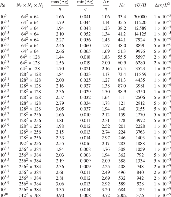
Appendix B. Prandtl-number dependence
In order to examine the effects of the Prandtl number  $Pr$ on the scaling of the Nusselt number $Nu$ and the Reynolds number $Re$ with the Rayleigh number, we have performed DNS of turbulent convection between the permeable walls for $Pr=7$. We inspect the ultimate scaling law
 \begin{equation} Nu\sim Pr^{1/2}Ra^{1/2}, \quad Re\sim Pr^{-1/2}Ra^{1/2}. \end{equation}
 Figure 12 shows  $Nu$ compensated by $Pr^{1/2}$ as a function of the Rayleigh number $Ra$ at $Pr=7$ and $Pr=1$ for the horizontal period $L/H=1$ and the permeability $\beta U=3$. The transition to the ultimate scaling $Nu\sim Pr^{1/2}Ra^{1/2}$ is also observed for $Pr=7$. In the supercritical $Ra$ range, the compensated $Nu$-plots roughly collapse onto a single line. The scaling behaviour in the subcritical $Ra$-range for $Pr=7$ is different from that for $Pr=1$, and the transition point seems to have a slight $Pr$ dependence.
The Nusselt number  $Nu$ compensated by $Pr^{1/2}$ as a function of the Rayleigh number $Ra$. The filled and open circles represent the present DNS data for $Pr=7$ and $Pr=1$ in the permeable case $\beta U=3$, respectively. The red and blue line indicate $Nu\sim Pr^{1/2}Ra^{1/2}$ and $Nu\sim Ra^{1/3}$, respectively. The inset shows $Nu$ compensated by $(RaPr)^{1/2}$.
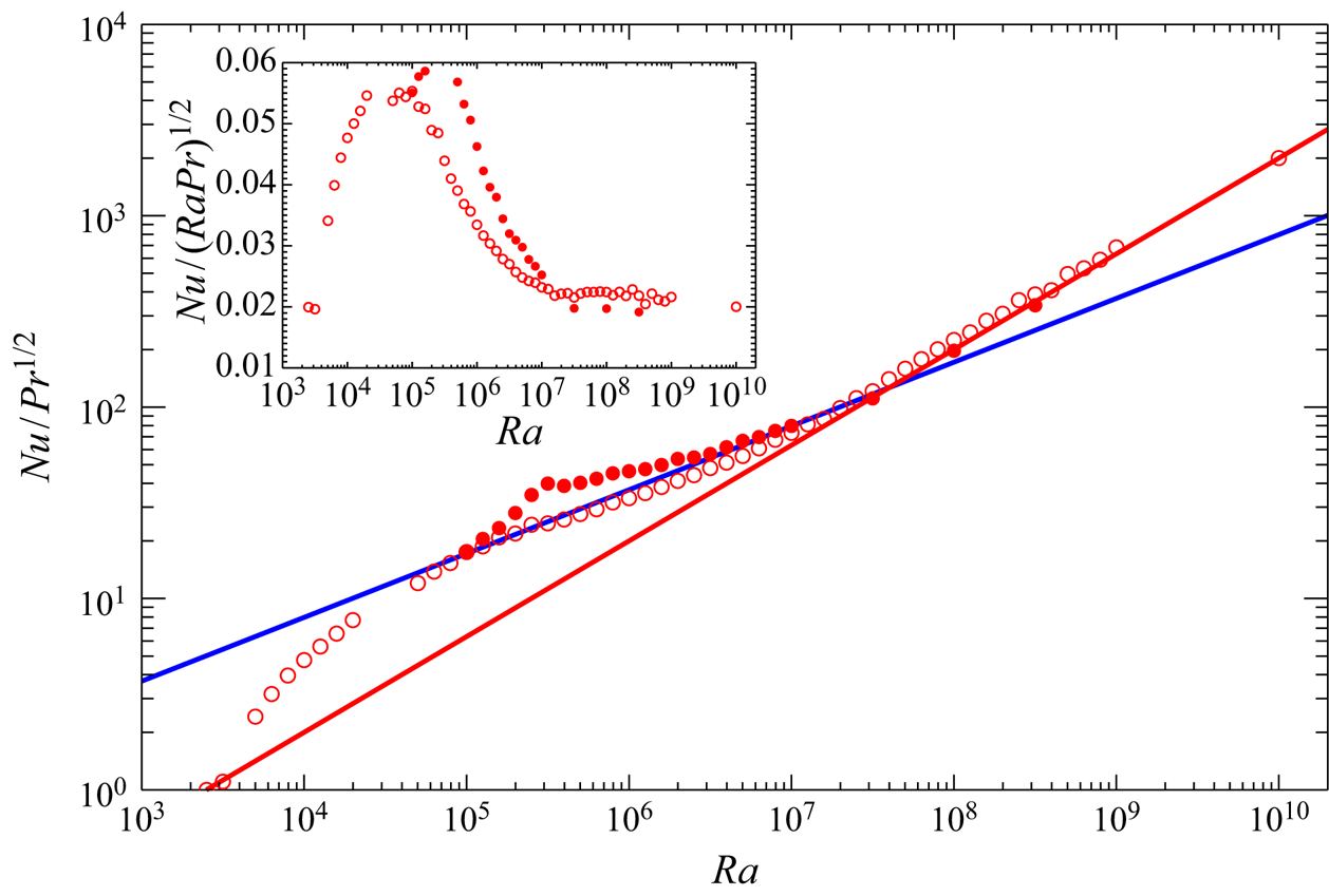
The critical transition is also observed in the RMS vertical velocity on the wall for  $Pr=7$ as shown in figure 13. We have confirmed that the other turbulent statistics and structures are similar to those observed for $Pr=1$.
The RMS vertical velocity on the wall  $z=0$ normalised by (a) $Ra^{-1/6}Pr^{1/6}U$ and (b) $U$ in the permeable case $\beta U=3$ for $Pr=7$.

In figure 14 is shown the Reynolds number
 \begin{equation} Re=\frac{\langle w^2\rangle_{xyzt}^{1/2}H}{\nu} \end{equation}
as a function of  $Ra$ in the permeable case for $Pr=1$ and $Pr=7$. We can see that in the supercritical permeable case, $Re$ scales with $Pr^{-1/2}Ra^{1/2}$ (or equivalently the RMS velocity scales with $U=(g\alpha \Delta T H)^{1/2}$), implying the ultimate scaling (see (5.11) in § 5 for physical interpretation of the ultimate scaling). In the subcritical permeable case, on the other hand, $Re$ seems to be proportional to $Ra^{4/9}$ as in the impermeable case (see (5.9) in § 5 for physical interpretation of the classical scaling).
The Reynolds number  $Re=\langle w^2\rangle _{xyzt}^{1/2}H/\nu$ compensated by $Pr^{-1/2}$ as a function of the Rayleigh number $Ra$. The filled and open circles represent the present DNS data for $Pr=7$ and $Pr=1$ in the permeable case $\beta U=3$, respectively. The red and blue line indicate $Re\sim Pr^{-1/2}Ra^{1/2}$ and $Re\sim Pr^{-2/3}Ra^{4/9}$, respectively. The inset shows $Re$ compensated by $Ra^{1/2}Pr^{-1/2}$.
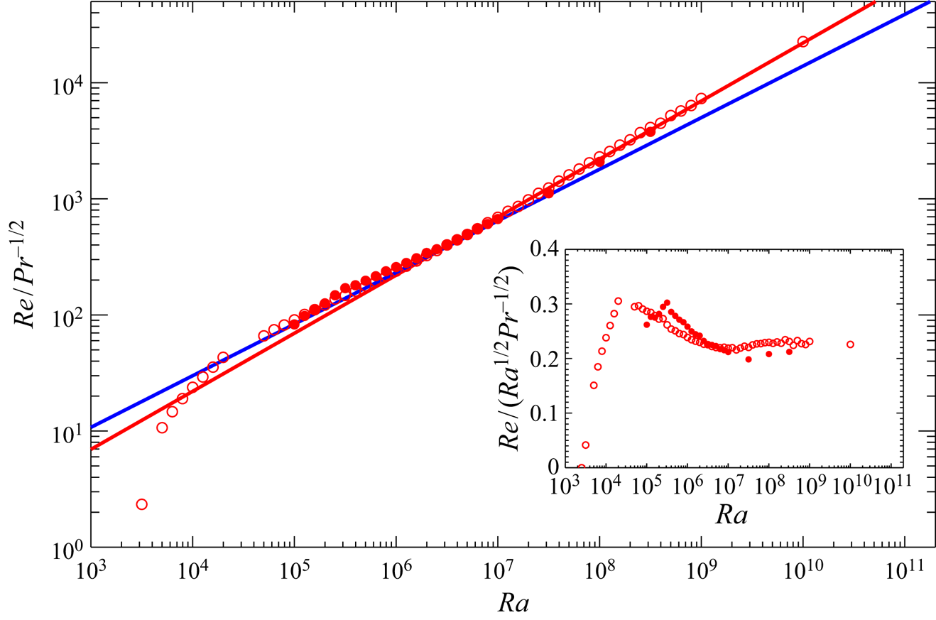


 Open access