1. Introduction
In recent years, the development of humanoid robots has garnered significant attention, primarily because advancements in humanoid structures hold the potential to replace labor-intensive tasks in the future and even serve as companion tools with emotional capabilities [Reference Aldawsari and Chen1]. The dual arms of humanoid robots are designed as redundant manipulators, capable of flexibly controlling end-effectors to perform a variety of precise tasks [Reference Li, Zhang and Jin2]. Simultaneously, dual arms can achieve joint-level obstacle avoidance during task execution [Reference Zhang, Zheng, Chen, Kong and Karimi3] and prevent reaching joint limit positions [Reference Yang, MacLachlan and Riviere4]. However, numerous challenges persist in the process of executing end-effector tasks with the dual arms of humanoid robots.
A fundamental issue for redundant manipulators is the inverse kinematics problem. As the degrees of freedom (DOFs) increase, the forward kinematics equations become nonlinear. This nonlinearity prevents real-time generation of joint trajectories and results in an infinite number of possible solutions for a single task. For humanoid robotic arms, selecting an appropriate solution presents various approaches. For instance, Singh et al. [Reference Singh and Claassens5] proposed parameterizing the elbow joint and deriving an analytical solution for the remaining DOF, limiting the solution space to a controllable range for selection. Another method involves iterative trajectory tracking through Jacobian matrix planning [Reference Nearchou6], and this approach offers good generality across different redundant manipulators but has notable drawbacks, particularly the computational burden of calculating the pseudoinverse of the matrix, which significantly impacts efficiency. Zhang et al. leveraged the flexibility of redundant robots by introducing a method based on the Jacobian pseudoinverse [Reference Zhang, Li, Gui and Luo7]. Their planning strategy decomposes the motion into a velocity component driving the end-effector toward the target and a null-space component for obstacle avoidance [Reference Maciejewski and Klein8]. However, the real-time computation of the pseudoinverse of the Jacobian for the obstacle avoidance component substantially increases computation time, leading to degraded planning performance and even introducing safety risks [Reference Wang, Liu, Liu, Chen and Lin9].
Due to the advantages of parallel computing and ease of implementation, recurrent neural network (RNN) method has been progressively introduced to solve inverse kinematics problems. Planning methods based on Quadratic Programming (QP) problems are particularly well suited for motion planning of redundant manipulators [Reference Zhang, Wang and Xia10]. By harnessing the parallel computing capabilities of RNN, optimal solutions to QP problems can be obtained. Furthermore, an RNN-based kinematic control scheme has been proposed to minimize the velocity norm during trajectory tracking [Reference Zhang and Wang11]. While solving QP problems with the objective of the velocity norm minimization optimizes the manipulator’s motion in a kinematic sense, it exhibits a clear deficiency in human-likeness. This is primarily because the generated joint configurations prioritize minimal velocity [Reference Wiedmeyer, Altoé, Auberle, Ledermann and Kröger12, Reference Faria, Ferreira, Erlhagen, Monteiro and Bicho13], rather than aligning with ergonomic principles or the optimal joint configurations for a dual-arm structure. Figure 1(a) depicts a reaching motion based on the velocity norm minimization, where the wrist joint notably lacks human-like behavior, differing significantly in naturalness from the normal human motion shown in (b) to reach the same point.
Fixed point motion of humanoid dual-arm robots. (a) Velocity norm minimization-based end-effector positioning and (b) natural humanoid motion for target reaching.

The inherent configuration of humanoid robots endows their dual arms with overlapping workspaces, necessitating explicit collision avoidance consideration during coordinated task execution. Effective collision prevention in overlapping regions requires both temporal-spatial decoupling of arm trajectories and inter-joint collision monitoring. Since joint angles can be acquired in real time, dynamic obstacle avoidance algorithms leveraging instantaneous joint state feedback provide an effective collision mitigation strategy. The RNN-based motion control framework demonstrates particular advantages in parallel computation. Zhang et al. [Reference Li, Zhang and Jin2] developed a modified collaborative algorithm (MCA) using RNN architecture, enabling real-time joint-level collision avoidance without compromising end-effector trajectory tracking accuracy. The artificial potential field (APF) method has proven effective in robotic collision avoidance [Reference Cai and Zhang14], operating through obstacle-induced repulsive forces and goal-directed attractive forces [Reference Khatib15]. Quan et al. [Reference Quan, Wang, Zhao, Lv, Zhao and Lv16] introduced an obstacle avoidance scheme based on redundant angle discretization for 7-DOF manipulators maintaining fixed end-effector poses, thereby offering a novel approach to planning collision-free solution sets for Cartesian trajectories. Csiszar et al. [Reference Csiszar, Drust, Dietz, Verl, Brisan, Jabloński and Březina17] enhanced APF by incorporating geometric obstacle representations, validating its efficacy through experimental studies. Hybrid approaches integrating fuzzy control logic have also emerged. For instance, Ref. [Reference Merchan-Cruz and Morris18] implemented a fuzzy-genetic strategy for dual-arm systems, treating each manipulator as a dynamic obstacle for its counterpart. Comprehensive collision avoidance must address both inter-joint interactions and end-effector trajectory adaptation. Wei et al. [Reference Wei, Wang, Hu and Lam19] proposed a convex optimization-based framework for online trajectory replanning in human–robot collaborative environments, dynamically adjusting motion trajectories according to task priority hierarchies. Compared to single-arm systems, multi-robot coordination further requires real-time task allocation optimization to maximize operational efficiency and rationalize workspace utilization [Reference Qin, Liao, Liu and Xiong20]. Khan et al. [Reference Khan, Li and Luo21] and Ijaz et al. [Reference Ijaz, Khan and Li22] formulated the problem using the beetle antennae search method and solved it using an RNN, maximizing the minimum distance between the robot and obstacles to achieve obstacle avoidance for manipulators or mobile robots against external objects of arbitrary shapes. Therefore, humanoid dual-arm coordination demands integrated solutions addressing both collision avoidance and joint motion optimization for enhanced workspace exploitation.
Humanoid dual-arm systems, designed with human biomechanical references, require simultaneous optimization of task precision and humanoid motion characteristics to fully exploit their biomimetic morphology. The fundamental challenge lies in generating joint angle trajectories that achieve both humanoid motion patterns and accurate end-effector tracking with obstacle avoidance capabilities. Quantifying humanoid motion features constitutes the foundation for humanoid control. Fitts’ law [Reference Fitts23] rooted in Shannon’ s information theory established quantitative relationships between arm movement velocity, acceleration, movement amplitude, and target dimensions. Uno [Reference Uno, Kawato and Suzuki24] proposed the minimum torque-change model through optimization of squared torque derivatives over motion cycles. Soechting [Reference Soechting, Buneo, Herrmann and Flanders25] developed the minimum work criterion focusing on mechanical energy minimization. Jung [Reference Jung and Choe26] introduced joint comfort metrics based on psychophysical studies of angular ranges and joint limits, suggesting that human motions inherently favor comfort-optimized joint configurations. Building upon these human motion quantifications, Li et al. [Reference Li, Han, He, Li, Liu and Xiong27] developed an humanoid inverse kinematics framework parameterizing the swivel angle, implementing an long short-term memory (LSTM)-based network trained on human motion datasets to generate natural joint configurations while maintaining end-effector precision. The Cartesian controller [Reference Pattacini, Nori, Natale, Metta and Sandini28] can generate quasi-linear humanoid trajectories with minimum jerk profiles characteristic of human motion. Reactive controllers in refs. [Reference Nguyen, Bottarel, Pattacini, Hoffmann, Natale and Metta29] and [Reference Nguyen, Hoffmann, Roncone, Pattacini and Metta30] employ minimum jerk trajectory sampling strategies. Suleiman [Reference Suleiman31] advanced an implicit minimum jerk trajectory generation algorithm by substituting joint velocities with jerk parameters in optimization formulations. For humanoid systems, humanoid motion is not merely a means of achieving more natural movement but also a way to optimally leverage the spatial capabilities of human joints and dual-arm configurations.
Therefore, building upon prior research foundations, this study proposes a novel joint angle control framework for redundant manipulators based on QP problems. Unlike conventional approaches solely minimizing velocity norm, our method introduces a joint discomfort minimization objective superimposed on the primary velocity optimization function. This dual optimization paradigm enables real-time joint angle adaptation during dual-arm operations, enhancing both naturalistic motion coordination and humanoid characteristics. Crucially, the RNN architecture maintains high-precision trajectory tracking and collision constraint resolution through its inherent parallel computing capabilities. By explicitly modeling manipulator redundancy, we formulate trajectory tracking and collision avoidance constraints into a multi-constrained optimization problem targeting joint discomfort minimization. A globally convergent RNN-based solver is developed to efficiently resolve this multi-constrained optimization in real time. The paper is organized as follows: Section II derives the constrained optimization framework integrating trajectory tracking, collision avoidance, and joint discomfort minimization. Section III reconstructs the primal problem at the velocity level and implements the projected RNN solution. Section IV validates method efficacy through simulations and physical experiments. Concluding remarks are provided in Section V. The primary contributions of this paper are as follows:
-
(1) The proposed RNN-based method can simultaneously address dual-arm dynamic collision avoidance and target tracking under multiple physical constraints.
-
(2) The joint discomfort minimization function adaptively adjusts joint configurations toward comfort-optimized angles without relaxing constraint enforcement, thereby enhancing both motion naturalness and dual-arm workspace utilization efficiency.
-
(3) Unlike traditional Jacobian Moore–Penrose Inverse (JMPI)-based methods, the proposed approach eliminates the need for pseudo-inverse calculations, thereby improving computational efficiency.
2. Problem formulation
2.1. Basic description
This study proposes a dual-arm motion planning framework that integrates joint discomfort minimization with joint collision avoidance and trajectory tracking constraints at the kinematic optimization level. The planning objectives for dual manipulators are primarily governed by three coupled requirements. First, the end-effectors must rigorously track predefined spatial trajectories; second, real-time inter-joint collision avoidance must be enforced during cooperative task execution in overlapping workspaces to prevent physical interference; finally, the integration of joint discomfort minimization enables dynamic joint motion adaptation, enhancing ergonomic motion naturalness while preventing kinematically anomalous configurations. This tri-objective optimization paradigm systematically coordinates joint space utilization, thereby reducing redundant collision avoidance maneuvers and improving operational fluency in constrained workspaces.
Let
 $ x \in \mathbb{R}^m$
, where
$ x \in \mathbb{R}^m$
, where
 $m$
is the task-space dimension of the robotic arm’s end-effector position. Then the relationship between the end-effector position and the joint angle
$m$
is the task-space dimension of the robotic arm’s end-effector position. Then the relationship between the end-effector position and the joint angle
 $ \theta \in \mathbb{R}^n$
(with
$ \theta \in \mathbb{R}^n$
(with
 $n$
being the number of DOF) is defined by the forward kinematics:
$n$
being the number of DOF) is defined by the forward kinematics:
 \begin{equation} x = f(\theta ) \end{equation}
where
 $ \theta \in \mathbb{R}^n$
, n is the DOF of the robot arm and
$ \theta \in \mathbb{R}^n$
, n is the DOF of the robot arm and
 $ f(\!\cdot\! )$
is the positive kinematics of the robot. The mapping relationship between
$ f(\!\cdot\! )$
is the positive kinematics of the robot. The mapping relationship between
 $ \dot x \in \mathbb{R}^m$
and
$ \dot x \in \mathbb{R}^m$
and
 $ \dot \theta \in \mathbb{R}^n$
at the velocity level is expressed as:
$ \dot \theta \in \mathbb{R}^n$
at the velocity level is expressed as:
 \begin{equation} \dot x = J(\theta )\dot \theta \end{equation}
where
 $J(\theta ) \in \mathbb{R}^{m \times n}$
is the Jacobian matrix. For redundant manipulators, the condition
$J(\theta ) \in \mathbb{R}^{m \times n}$
is the Jacobian matrix. For redundant manipulators, the condition
 $m\lt n$
holds, enabling infinite joint space solutions for a given task-space trajectory.
$m\lt n$
holds, enabling infinite joint space solutions for a given task-space trajectory.
During the execution of collaborative dual-arm tasks, humanoid robots face the risk of arm collisions. Collision detection methods based on bounding volume-based are commonly employed to determine whether a robot collides with its external environment. We specifically adopt spherical bounding volumes (SBVs) to characterize the robot’s kinematic configuration, enabling efficient real-time collision avoidance through analytical distance computation. To distinguish between the SBVs of the left and right arms, we denote
 ${}^rA_i$
and
${}^rA_i$
and
 ${}^rJ_i$
as the i-th SBV center and corresponding Jacobian matrix for the left arm, respectively, and
${}^rJ_i$
as the i-th SBV center and corresponding Jacobian matrix for the left arm, respectively, and
 ${}^lA_j$
and
${}^lA_j$
and
 ${}^lJ_j$
as the j-th SBV center and corresponding Jacobian matrix for the right arm, respectively.
${}^lJ_j$
as the j-th SBV center and corresponding Jacobian matrix for the right arm, respectively.
Spherical bounding volume-based dual-arm manipulators.

As illustrated in Figure 2, let the SBV centers for the right manipulator be represented by the matrix
 ${}^rA = [{}^rA_1,\ldots ,{}^rA_a,{}^rA_{(a+1)},\ldots ,{}^rA_{(a+b)}] \in \mathbb{R}^{m \times (a+b)}$
where
${}^rA = [{}^rA_1,\ldots ,{}^rA_a,{}^rA_{(a+1)},\ldots ,{}^rA_{(a+b)}] \in \mathbb{R}^{m \times (a+b)}$
where
 $m$
denotes the spatial dimension,
$m$
denotes the spatial dimension,
 $a$
and
$a$
and
 $b$
respectively represent the number of SBVs allocated to the forearm and end-effector segments. The corresponding SBV radii are defined as
$b$
respectively represent the number of SBVs allocated to the forearm and end-effector segments. The corresponding SBV radii are defined as
 $r_1$
(forearm) and
$r_1$
(forearm) and
 $r_2$
(end-effector). Similarly, the left manipulator’s SBV centers are represented by the matrix
$r_2$
(end-effector). Similarly, the left manipulator’s SBV centers are represented by the matrix
 ${}^lA = [{}^lA_1,\ldots ,{}^lA_a,{}^lA_{(a+1)},\ldots ,{}^lA_{(a+b)}] \in \mathbb{R}^{m \times (a+b)}$
. The sufficient condition for collision-free dual-arm operation requires that for any pair of SBV centers
${}^lA = [{}^lA_1,\ldots ,{}^lA_a,{}^lA_{(a+1)},\ldots ,{}^lA_{(a+b)}] \in \mathbb{R}^{m \times (a+b)}$
. The sufficient condition for collision-free dual-arm operation requires that for any pair of SBV centers
 ${}^rA_i \in {}^rA$
and
${}^rA_i \in {}^rA$
and
 $ {}^lA_j \in {}^lA$
, the following inequality holds
$ {}^lA_j \in {}^lA$
, the following inequality holds
 $|| {}^rA_i - {}^lA_j||_2^2 \ge D$
, where the safety threshold
$|| {}^rA_i - {}^lA_j||_2^2 \ge D$
, where the safety threshold
 $D$
is determined by
$D$
is determined by
 $D = R_r + R_l + \Delta d$
, with
$D = R_r + R_l + \Delta d$
, with
 $ R_r \in \{r_1,r_2\}$
and
$ R_r \in \{r_1,r_2\}$
and
 $ R_l \in \{r_1,r_2\}$
denoting the SBV radii of the right and left manipulators, respectively, and
$ R_l \in \{r_1,r_2\}$
denoting the SBV radii of the right and left manipulators, respectively, and
 $\Delta d \gt 0$
specifying the redundant safety margin. According to the velocity escape method [Reference Zhang and Wang11],
$\Delta d \gt 0$
specifying the redundant safety margin. According to the velocity escape method [Reference Zhang and Wang11],
 $||{}^rA_i - {}^lA_j||_2^2 \ge D$
is described as a kinematic function as follows:
$||{}^rA_i - {}^lA_j||_2^2 \ge D$
is described as a kinematic function as follows:
 \begin{equation} \begin{split} \frac{\text{d}}{\text{d}t} ||{}^rA_i - {}^lA_j||_2^2 & \ge K(D - ||{}^rA_i - {}^lA_j||_2^2) \\[3pt] i, j &= 1, 2, \ldots , (a + b) \end{split} \end{equation}
The kinematic mapping between SBV center coordinates and joint angles satisfies
 ${}^rA_i={}^rf_i(\theta _r)$
,
${}^rA_i={}^rf_i(\theta _r)$
,
 ${}^lA_j={}^lf_j(\theta _l)$
, where
${}^lA_j={}^lf_j(\theta _l)$
, where
 ${}^rf_i(\!\cdot\! )$
and
${}^rf_i(\!\cdot\! )$
and
 ${}^lf_j(\!\cdot\! )$
denote forward kinematics functions for respective SBV centers. The velocity propagation is governed by Jacobian matrices
${}^lf_j(\!\cdot\! )$
denote forward kinematics functions for respective SBV centers. The velocity propagation is governed by Jacobian matrices
 ${}^r{\dot A} = {}^rJ_i {\dot \theta }_r$
and
${}^r{\dot A} = {}^rJ_i {\dot \theta }_r$
and
 ${}^l{\dot A} = {}^lJ_j {\dot \theta _l}$
. The temporal derivative of SBV center distance is derived as:
${}^l{\dot A} = {}^lJ_j {\dot \theta _l}$
. The temporal derivative of SBV center distance is derived as:
 \begin{align} \begin{split} \frac{\text{d}}{\text{d}t} ||{}^rA_i - {}^lA_j||_2^2 &= \frac{\text{d}}{\text{d}t} \left ( \sqrt {({}^rA_i - {}^lA_j)^T ({}^rA_i - {}^lA_j)} \right ) \\[2pt] &= \frac {1}{\|{}^rA_i - {}^lA_j}\|_2^2 ({}^rA_i - {}^lA_j)^T ({}^r{\dot A_i} - {}^r{\dot A_j}) \\[2pt] &= \frac {1}{\|{{}^rA_i - {}^lA_j}\|_2^2} \left ( {}^rA_i - {}^lA_j \right )^T \left ( {}^rJ_i {\dot {\theta }}_r - {}^lJ_j {\dot {\theta }_l} \right ) \end{split} && \end{align}
 \begin{equation} \begin{split} {\overrightarrow {{}^rA_i-{}^lA_j}}^T [{}^rJ_i, -{}^lJ_j]\big[{\dot \theta }^T_r,{\dot \theta ^T_l}\big]^T \geq K \left (D - \|{}^rA_i - {}^lA_j\|_2^2 \right ) \end{split} \end{equation}
where
 ${\overrightarrow {{}^rA_i-{}^lA_j}}^T = \frac {({}^rA_i - {}^lA_j)^T}{\|{}^rA_i - {}^lA_j\|_2^2}$
is the unit vector from
${\overrightarrow {{}^rA_i-{}^lA_j}}^T = \frac {({}^rA_i - {}^lA_j)^T}{\|{}^rA_i - {}^lA_j\|_2^2}$
is the unit vector from
 ${}^lA_j$
to
${}^lA_j$
to
 ${}^rA_i$
and
${}^rA_i$
and
 $K \gt 0$
. To ensure comprehensive collision avoidance, all SBV centers must satisfy (5). This leads to the aggregated constraint:
$K \gt 0$
. To ensure comprehensive collision avoidance, all SBV centers must satisfy (5). This leads to the aggregated constraint:
 \begin{equation} \begin{split} J_{\text{ob}}[{\dot \theta ^T_r},{\dot \theta }^T_l]^T \leq K D_{\text{dis}} \end{split} \end{equation}
where
 \begin{align*} J_{\text{ob}} = \begin{bmatrix} -\:{\overrightarrow {{}^rA_1-{}^lA_1}}^T {}^rJ_1 & \:{\overrightarrow {{}^rA_1-{}^lA_1}}^T {}^lJ_1 \\ \vdots & \vdots \\ -\:{\overrightarrow {{}^rA_1-{}^lA_b}}^T {}^rJ_{1} & \:{\overrightarrow {{}^rA_1-{}^lA_b}}^T {}^lJ_b \\ \vdots & \vdots \\ -\:{\overrightarrow {{}^rA_a-{}^lA_1}}^T {}^rJ_{a} & \:{\overrightarrow {{}^rA_a-{}^lA_1}}^T {}^lJ_{1} \\ \vdots & \vdots \\ -\:{\overrightarrow {{}^rA_a-{}^lA_b}}^T {}^rJ_{a} & \:{\overrightarrow {{}^rA_a-{}^lA_b}}^T {}^lJ_{b} \end{bmatrix} \in \mathbb{R}^{(a+b)^2 \times 2m} , D_{\text{dis}} = \begin{bmatrix} \| {}^rA_1 - {}^lA_1 \|_2^2 - D \\ \vdots \\ \| {}^rA_1 - {}^lA_b \|_2^2 - D \\ \vdots \\ \| {}^rA_a - {}^lA_1 \|_2^2 - D \\ \vdots \\ \| {}^rA_a - {}^lA_b \|_2^2 - D \end{bmatrix} \in \mathbb{R}^{(a+b)^2}. \end{align*}
The structure of
 $J_{\text{ob}}$
explicitly accounts for counteracting velocity components between manipulators, fully taking into account the relative motion of the dual arms.
$J_{\text{ob}}$
explicitly accounts for counteracting velocity components between manipulators, fully taking into account the relative motion of the dual arms.
Conventional dual-arm motion planning algorithms, predominantly based on velocity norm minimization, often neglect critical humanoid-specific constraints such as shoulder/waist joint limits and workspace boundaries. This oversight leads to two detrimental effects in overlapping workspace operations: (1) tendency to approach joint limit thresholds, compromising end-effector precision and (2) generation of kinematically unnatural arm configurations. As demonstrated in Figure 1(a), minimizing velocity norm solutions frequently drive shoulder joints toward mechanical limits, whereas it can be seen from Figure 1(b) that (b) is superior to (a) in terms of the naturalness of the joint and is not approaching the joint limit position. Therefore, this paper improves upon the traditional optimization objective of the velocity norm minimization by proposing a new optimization target – joint discomfort minimization – that is better suited to human joint motion. In ergonomic studies, the motion of both arms is influenced by the elastic potential energy of muscles and gravitational potential energy [Reference Zhao, Xie and Song32]. The greater the elastic and gravitational potential energies experienced during arm movement, the lower the comfort level of the arms.
Joint discomfort is derived from VSR [Reference Yang, Marler and Kim33], which defines a neutral position during motion, termed the joint comfort angle, where the comfort of each joint angle is maximized. For biological organisms in natural states – whether in motion or at rest – the minimization of total potential energy (formulated as the aggregation of elastic and gravitational potential energies) corresponds to the state of maximum joint comfort. This implies that biological systems inherently seek an optimal configuration characterized by minimum joint discomfort. This principle constitutes a pivotal direction in current research on natural humanoid motion: the minimization of motion-related total potential energy correlates directly with enhanced naturalness and anthropomorphism in the motion process.
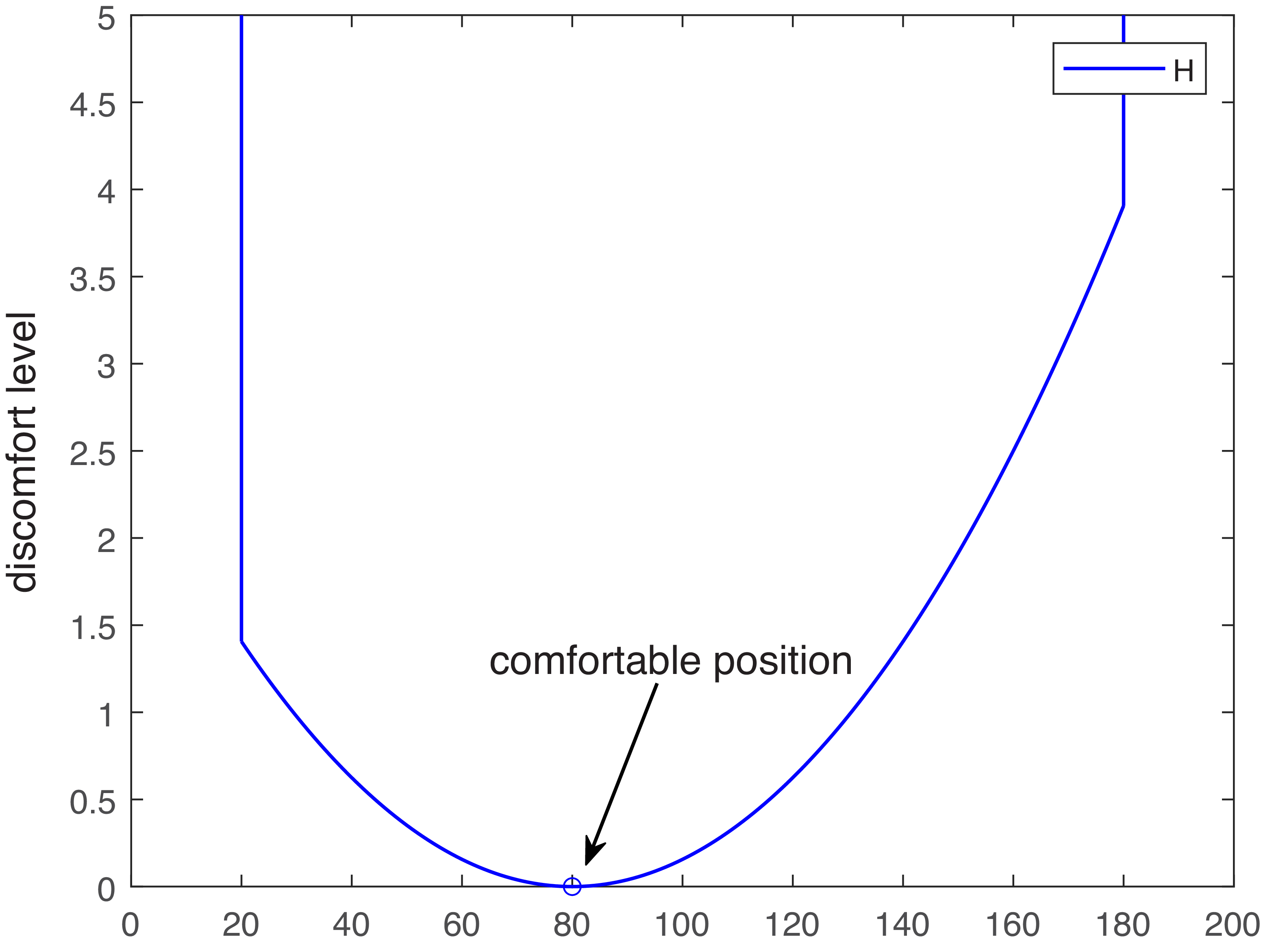
The degree of joint discomfort is evaluated based on the joint’s rotational position relative to its upper and lower limits, with discomfort increasing significantly as the joint approaches these limits. In Ref. [Reference Ma, Zhang, Chablat, Bennis and Guillaume34], joint discomfort was proposed as an objective function for predicting human postures. To ensure the objective function remains convex, the target function is described as follows:
 \begin{equation} \begin{split} H_{\text{discomfort}}(\theta ) = \sum _{i=1}^{n}\beta (i) \left ( \frac {\theta (i) - \theta _{\text{comfort}}(i)}{\theta _{\text{max}}(i) - \theta _{\text{min}}(i)} \right )^2 \end{split} \end{equation}
where
 $n$
is the DOFs of the robotic arm;
$n$
is the DOFs of the robotic arm;
 $\beta (i),\theta (i),\theta _{\text{max}}(i),\theta _{\text{min}}(i)$
represent the comfort weight coefficient, joint angle, upper joint angle limit, and lower joint angle limit of the
$\beta (i),\theta (i),\theta _{\text{max}}(i),\theta _{\text{min}}(i)$
represent the comfort weight coefficient, joint angle, upper joint angle limit, and lower joint angle limit of the
 $i$
-th joint, respectively. An example of joint discomfort calculation is illustrated in Figure 3. The overall joint discomfort reaches its minimum at the joint comfort angle position, while discomfort increases as the joint approaches its upper or lower limits. Joint discomfort is typically used in ergonomics to assess the comfort of individual movements, without considering other constraining factors. This paper adapts this metric for velocity-level optimization to enhance the comfort and naturalness of robot joint motions, while accounting for additional constraints.
$i$
-th joint, respectively. An example of joint discomfort calculation is illustrated in Figure 3. The overall joint discomfort reaches its minimum at the joint comfort angle position, while discomfort increases as the joint approaches its upper or lower limits. Joint discomfort is typically used in ergonomics to assess the comfort of individual movements, without considering other constraining factors. This paper adapts this metric for velocity-level optimization to enhance the comfort and naturalness of robot joint motions, while accounting for additional constraints.
An example of the joint discomfort,
 $\theta _{\text{comfort}}=80 , \theta _{\text{max}}=180,\theta _{\text{min}}=20$
(°).
$\theta _{\text{comfort}}=80 , \theta _{\text{max}}=180,\theta _{\text{min}}=20$
(°).

2.2. Control objective
During the motion of a humanoid robot’s dual-arm system, the system is constrained by its mechanical structure and motor performance. Consequently, in practical scenarios, both the joint angles
 $\theta$
and joint angular velocity
$\theta$
and joint angular velocity
 $\dot \theta$
are subject to upper and lower limits. In the actual planning process for dual arms, it is necessary to separately consider the joint angles
$\dot \theta$
are subject to upper and lower limits. In the actual planning process for dual arms, it is necessary to separately consider the joint angles
 $\theta _r$
and
$\theta _r$
and
 $\theta _l$
and the joint angular velocities
$\theta _l$
and the joint angular velocities
 $\dot \theta _r$
and
$\dot \theta _r$
and
 $\dot \theta _l$
of the right and left arms, respectively, ensuring that neither arm exceeds its limits. Thus, the constraints are defined as
$\dot \theta _l$
of the right and left arms, respectively, ensuring that neither arm exceeds its limits. Thus, the constraints are defined as
 $\theta ^-_r\lt \theta _r\lt \theta ^+_r, \theta ^-_l\lt \theta _l\lt \theta ^+_l, \dot \theta ^-_r\lt \dot \theta _r\lt \dot \theta ^+_r, \dot \theta ^-_l\lt \dot \theta _l\lt \dot \theta _l$
, where
$\theta ^-_r\lt \theta _r\lt \theta ^+_r, \theta ^-_l\lt \theta _l\lt \theta ^+_l, \dot \theta ^-_r\lt \dot \theta _r\lt \dot \theta ^+_r, \dot \theta ^-_l\lt \dot \theta _l\lt \dot \theta _l$
, where
 $\theta ^-_r,\theta ^-_l,\theta ^+_r,\theta ^+_l$
represent the lower and upper bounds of the joint angles for the right and left arms, respectively, and
$\theta ^-_r,\theta ^-_l,\theta ^+_r,\theta ^+_l$
represent the lower and upper bounds of the joint angles for the right and left arms, respectively, and
 $\dot \theta ^-_r,\dot \theta ^-_l,\dot \theta ^+_r,\dot \theta ^+_l$
denote the lower and upper bounds of the joint angular velocities for the right and left arms, respectively. For a redundant dual-arm manipulator, the control task of joint discomfort minimization is selected.
$\dot \theta ^-_r,\dot \theta ^-_l,\dot \theta ^+_r,\dot \theta ^+_l$
denote the lower and upper bounds of the joint angular velocities for the right and left arms, respectively. For a redundant dual-arm manipulator, the control task of joint discomfort minimization is selected.
For a redundant manipulator
 $x = f(\theta )$
, given the desired positions of the dual-arm end-effectors
$x = f(\theta )$
, given the desired positions of the dual-arm end-effectors
 $x_{rd}$
and
$x_{rd}$
and
 $x_{ld}$
, the joint velocity vectors
$x_{ld}$
, the joint velocity vectors
 $\dot {\theta }_r$
and
$\dot {\theta }_r$
and
 $\dot {\theta }_l$
are planned to approach
$\dot {\theta }_l$
are planned to approach
 ${}^rx_{d}$
and
${}^rx_{d}$
and
 ${}^lx_{d}$
, while ensuring that the dual-arm manipulator do not collide during the planned motion. The optimization problem is formulated as follows:
${}^lx_{d}$
, while ensuring that the dual-arm manipulator do not collide during the planned motion. The optimization problem is formulated as follows:
 \begin{align} \text{min} &\quad \frac {1}{2} \dot {\theta }_r^T \dot {\theta }_r + H_r + \frac {1}{2} \dot {\theta }_l^T \dot {\theta }_l + H_l \\[-10pt] \nonumber\end{align}
 \begin{align} \text{s.t.} &\quad {}^rx_{d} = f(\theta _r) \\[-10pt] \nonumber\end{align}
 \begin{align} &\quad {}^lx_{d} = f(\theta _l) \\[-10pt] \nonumber\end{align}
 \begin{align} &\quad \theta _r^- \lt \theta _r \lt \theta _r^+ \\[-10pt] \nonumber \end{align}
 \begin{align} &\quad \theta _l^- \lt \theta _l \lt \theta _l^+ \\[-10pt] \nonumber \end{align}
 \begin{align} &\quad \dot {\theta }_r^- \lt \dot {\theta }_r \lt \dot {\theta }_r^+ \\[-10pt] \nonumber \end{align}
 \begin{align} &\quad \dot {\theta }_l^- \lt \dot {\theta }_l \lt \dot {\theta }_l^+ \\[-10pt] \nonumber \end{align}
 \begin{align} &\quad J_{\text{ob}} \big[\dot {\theta }_r^T, \dot {\theta }_l^T\big]^T \leq K D_{\text{dis}} \end{align}
let
 $\theta = [\theta _r^T,\theta _l^T]^T$
,
$\theta = [\theta _r^T,\theta _l^T]^T$
,
 $H = H_r+H_l$
,
$H = H_r+H_l$
,
 $\theta ^- = [(\theta _r^-)^T,(\theta _l^-)^T]^T$
,
$\theta ^- = [(\theta _r^-)^T,(\theta _l^-)^T]^T$
,
 $\theta ^+ = [(\theta _r^+)^T,(\theta _l^+)^T]^T$
,
$\theta ^+ = [(\theta _r^+)^T,(\theta _l^+)^T]^T$
,
 $\dot \theta ^- = [(\dot \theta _r^-)^T,(\dot \theta _l^-)^T]^T$
,
$\dot \theta ^- = [(\dot \theta _r^-)^T,(\dot \theta _l^-)^T]^T$
,
 $\dot \theta ^+ = [(\dot \theta _r^+)^T,(\dot \theta _l^+)^T]^T$
, and
$\dot \theta ^+ = [(\dot \theta _r^+)^T,(\dot \theta _l^+)^T]^T$
, and
 $x_d = [{}^rx_{d}^T,{}^lx_{d}^T]^T$
. Equation (8) can be reformulated as follows:
$x_d = [{}^rx_{d}^T,{}^lx_{d}^T]^T$
. Equation (8) can be reformulated as follows:
 \begin{align} \text{min} &\quad \frac {1}{2} \dot {\theta }^T \dot {\theta } + H \\[-10pt] \nonumber \end{align}
 \begin{align} \text{s.t.} &\quad x_d = f(\theta ) \\[-10pt] \nonumber \end{align}
 \begin{align} &\quad \theta ^- \lt \theta \lt \theta ^+ \\[-10pt] \nonumber\end{align}
 \begin{align} &\quad \dot {\theta }^- \lt \dot {\theta } \lt \dot {\theta }^+ \\[-10pt] \nonumber\end{align}
 \begin{align} &\quad J_{\text{ob}} \dot {\theta } \leq K D_{\text{dis}} \\[4pt] \nonumber \end{align}
2.3. QP-type problem reformulation
From Eq. (9), it can be observed that (9d) and (9e) describe the velocity level, (9b) and (9c) describe the position level, while (9a) involves descriptions at both the position and velocity levels. This makes the equation difficult to solve in real time. Therefore, in this section, Eq. (9) is transformed into a QP problem description at the velocity level.
-
(1) Optimization target reconstruction ( 9a )
The optimization objective
 $H$
is reformulated at the velocity level by taking the partial derivative with respect to time. Consequently, the time derivative is expressed as
$H$
is reformulated at the velocity level by taking the partial derivative with respect to time. Consequently, the time derivative is expressed as
 $\frac {\partial H}{\partial t} = \sum _{i=1}^{n} \frac {\partial }{\partial t} \left ( \beta _i \left ( \frac {\theta _i - \theta _{\text{comfort}, i}}{\theta _{\text{max}, i} - \theta _{\text{min}, i}} \right )^2 \right )$
. The resulting equation is detailed as follows:
$\frac {\partial H}{\partial t} = \sum _{i=1}^{n} \frac {\partial }{\partial t} \left ( \beta _i \left ( \frac {\theta _i - \theta _{\text{comfort}, i}}{\theta _{\text{max}, i} - \theta _{\text{min}, i}} \right )^2 \right )$
. The resulting equation is detailed as follows:
 \begin{equation} \begin{split} \dot H = \sum _{i=1}^{n} \left (\frac {2\beta (i)\left (\theta (i) - \theta _{\text{comfort}}(i)\right )}{\left ( {\theta (i)}^+-{\theta (i)}^-\right )^2} \dot \theta (i)\right ) \end{split} \end{equation}
By performing a matrix transformation on this equation, the following expression is obtained:
 \begin{equation} \dot {H} = \left ( \tilde {\beta } \cdot \Delta \theta \right )^T \dot {\theta } \end{equation}
where
 $ \tilde {\beta } \in \mathbb{R}^{14 \times 1}$
,
$ \tilde {\beta } \in \mathbb{R}^{14 \times 1}$
,
 $ \tilde {\beta }(i) = \frac {2 \beta (i)}{({\theta (i)}^+ - {\theta (i)}^-)^2}$
,
$ \tilde {\beta }(i) = \frac {2 \beta (i)}{({\theta (i)}^+ - {\theta (i)}^-)^2}$
,
 $ \Delta \theta \in \mathbb{R}^{14 \times 1}$
, and
$ \Delta \theta \in \mathbb{R}^{14 \times 1}$
, and
 $ \Delta \theta (i) = \theta (i) - \theta _{\text{comfort}}(i)$
, and
$ \Delta \theta (i) = \theta (i) - \theta _{\text{comfort}}(i)$
, and
 $ (\!\cdot\! )$
denotes the element-wise multiplication of matrices.
$ (\!\cdot\! )$
denotes the element-wise multiplication of matrices.
The physical description of the optimization objective in this reformulation process is as follows: based on the deviation between the current joint angle and the joint comfort angle, the current joint angular velocity is further optimized to approach the joint comfort angle while satisfying other constraints, thereby minimizing joint discomfort under the given constraints. Therefore, based on Eq. (9), the optimization objective can be reconstructed at the velocity level as:
 \begin{equation} \text{min} \quad \frac {1}{2} \dot {\theta }^T \dot {\theta } + \left ( \tilde {\beta } \cdot \Delta \theta \right )^T \dot {\theta } \end{equation}
-
(2) Reconstruction of Equality Constraint ( 9b )
To transform constraints (9b) into velocity-level equality constraints, the planning error
 $ e$
is defined as
$ e$
is defined as
 $ e = x - x_d$
. The evolution equation is given by:
$ e = x - x_d$
. The evolution equation is given by:
 \begin{equation} \dot {e} = -\gamma \Phi (e) \end{equation}
where
 $ \gamma$
and
$ \gamma$
and
 $ \Phi (\!\cdot\! )$
represent a positive constant and a monotonically increasing odd function, respectively. Combining Eqs. (1), (2), and (13), we obtain
$ \Phi (\!\cdot\! )$
represent a positive constant and a monotonically increasing odd function, respectively. Combining Eqs. (1), (2), and (13), we obtain
 \begin{equation} J \dot {\theta } = \dot {x}_d - \gamma \Phi (e) \end{equation}
where
 $ J = \begin{bmatrix} J_r &\quad 0 \\[1pt] 0 &\quad J_l \end{bmatrix}$
. It can be noted that by rewriting (9b),
$ J = \begin{bmatrix} J_r &\quad 0 \\[1pt] 0 &\quad J_l \end{bmatrix}$
. It can be noted that by rewriting (9b),
 $ \dot {\theta }$
is subject to equality constraints. Although
$ \dot {\theta }$
is subject to equality constraints. Although
 $ \dot {\theta }$
can be obtained from the pseudoinverse of
$ \dot {\theta }$
can be obtained from the pseudoinverse of
 $ J$
, the redundancy of the Jacobian matrix implies that the solution for
$ J$
, the redundancy of the Jacobian matrix implies that the solution for
 $ \dot {\theta }$
is not unique. Through additional inequality constraints and the objective function (9c–9e), this implicit formulation can fully use the redundant DOF of the robot.
$ \dot {\theta }$
is not unique. Through additional inequality constraints and the objective function (9c–9e), this implicit formulation can fully use the redundant DOF of the robot.
-
(3) Inequality constraint reconstruction:
The joint inequality constraint (9c) is reconstructed into a velocity-level description. For a joint angle
 $ \theta (t)$
at a specific time instant, let
$ \theta (t)$
at a specific time instant, let
 $ \theta ^+ - \theta (t)$
represent the difference between
$ \theta ^+ - \theta (t)$
represent the difference between
 $ \theta (t)$
and its upper bound
$ \theta (t)$
and its upper bound
 $ \theta ^+$
. According to the velocity escape method [Reference Zhang and Wang11], it can be proven that when
$ \theta ^+$
. According to the velocity escape method [Reference Zhang and Wang11], it can be proven that when
 $ \dot {\theta }$
satisfies the following inequality,
$ \dot {\theta }$
satisfies the following inequality,
 $ \theta (t) \leq \theta ^+$
always holds:
$ \theta (t) \leq \theta ^+$
always holds:
 \begin{equation} \dot {\theta } \leq \alpha (\theta ^+ - \theta (t)) \end{equation}
where
 $ \alpha \gt 0$
is a positive constant. Similarly, the lower bound constraint on the joint angle,
$ \alpha \gt 0$
is a positive constant. Similarly, the lower bound constraint on the joint angle,
 $ \theta ^-\leq \theta (t)$
, can be described as:
$ \theta ^-\leq \theta (t)$
, can be described as:
 \begin{equation} \dot {\theta } \geq \alpha (\theta ^- - \theta (t)) \end{equation}
By combining Eqs. (9c), (9d), (15), and (16), the reformulated inequality constraint can be expressed as:
 \begin{equation} \text{max}(\alpha (\theta ^- - \theta (t)), \dot {\theta }^-) \leq \dot {\theta } \leq \text{min}(\dot {\theta }^+, \alpha (\theta ^+ - \theta (t))) \end{equation}
Thus far, through the reconstruction of equality and inequality constraints, the resulting QP problem is formulated as follows:
 \begin{align} \text{min} &\quad \frac {1}{2} \dot {\theta }^T \dot {\theta } + \left ( \tilde {\beta } \cdot \Delta \theta \right )^T \dot {\theta } \\[-10pt] \nonumber \end{align}
 \begin{align} \text{s.t.} &\quad J \dot {\theta } = \dot {x}_d - \gamma \Phi (e) \\[-10pt] \nonumber \end{align}
 \begin{align} \quad \max (\alpha &(\theta ^- - \theta (t)), \dot {\theta }^-) \leq \dot {\theta } \leq \min (\dot {\theta }^+, \alpha (\theta ^+ - \theta (t))) \\[-10pt] \nonumber \end{align}
 \begin{align} &\quad J_{ob} \dot {\theta } \leq K D_{dis} \\[6pt] \nonumber \end{align}
As described in Eq. (18), the solution
 $ \dot {\theta }$
of the QP problem simultaneously satisfies the equality constraint (18b) and the inequality constraints (18c) and (18d), which correspond to the convergence of the motion planning error, joint constraints, and self-collision avoidance constraints of the dual arms, respectively. Furthermore, to ensure that the joint motion of the humanoid dual arms tends to minimize joint discomfort during the execution of the planned motion, a linear term
$ \dot {\theta }$
of the QP problem simultaneously satisfies the equality constraint (18b) and the inequality constraints (18c) and (18d), which correspond to the convergence of the motion planning error, joint constraints, and self-collision avoidance constraints of the dual arms, respectively. Furthermore, to ensure that the joint motion of the humanoid dual arms tends to minimize joint discomfort during the execution of the planned motion, a linear term
 $ (\tilde {\beta } \cdot \Delta \theta )^T \dot {\theta }$
is added to the joint velocity term
$ (\tilde {\beta } \cdot \Delta \theta )^T \dot {\theta }$
is added to the joint velocity term
 $ \dot {\theta }^T \dot {\theta }$
. This aims to achieve an overall minimum of the Euclidean norm and joint discomfort, optimizing the joint velocities in real time to make the dual-arm motion more natural and humanoid. Therefore, the motion planning problem of minimizing joint discomfort and achieving dynamic obstacle avoidance for the redundant dual-arm manipulator is transformed into solving the QP problem in real time.
$ \dot {\theta }^T \dot {\theta }$
. This aims to achieve an overall minimum of the Euclidean norm and joint discomfort, optimizing the joint velocities in real time to make the dual-arm motion more natural and humanoid. Therefore, the motion planning problem of minimizing joint discomfort and achieving dynamic obstacle avoidance for the redundant dual-arm manipulator is transformed into solving the QP problem in real time.
3. RNN-based solver design
3.1. RNN design
To address the constrained optimization problem (18), let
 $ L$
be the Lagrange function defined as:
$ L$
be the Lagrange function defined as:
 \begin{equation} \begin{split} L = & \frac {1}{2} \dot {\theta }^T \dot {\theta } + \left ( \tilde {\beta } \cdot \Delta \theta \right )^T \dot {\theta } \\[3pt] & + \lambda _1^T (\dot {x}_d - \gamma \Phi (e) - J \dot {\theta }) \\[3pt] & + \lambda _2^T (J_{\text{ob}} \dot {\theta } - K D_{\text{dis}}) \end{split} \end{equation}
where
 $ \lambda _1 \in \mathbb{R}^{2m}$
and
$ \lambda _1 \in \mathbb{R}^{2m}$
and
 $ \lambda _2 \in \mathbb{R}^{(a+b)^2}$
are the dual-state variables of the dual arms, corresponding to the constraints in (18b) and (18d), respectively. Using the Karush–Kuhn–Tucker (KKT) conditions, the solution to Eq. (18) satisfies:
$ \lambda _2 \in \mathbb{R}^{(a+b)^2}$
are the dual-state variables of the dual arms, corresponding to the constraints in (18b) and (18d), respectively. Using the Karush–Kuhn–Tucker (KKT) conditions, the solution to Eq. (18) satisfies:
 \begin{align} &\dot {\theta } = P_\Omega \left ( \dot {\theta } - \frac {\partial L}{\partial \dot {\theta }} \right ) \\[-10pt] \nonumber \end{align}
 \begin{align} &J(\theta ) \dot {\theta } = \dot {x}_d - \gamma \Phi (e) \\[-10pt] \nonumber \end{align}
 \begin{align} &\begin{cases} \lambda _2 \gt 0 & \text{if } J_{\text{ob}} \dot {\theta } \gt K D_{\text{dis}} \\ \lambda _2 = 0 & \text{if } J_{\text{ob}} \dot {\theta } \leq K D_{\text{dis}} \end{cases} \\[12pt] \nonumber\end{align}
in which
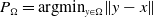 $ P_\Omega = \text{argmin}_{y \in \Omega } \| y - x \|$
is the saturation operator corresponding to the joint velocity constraint (18c), where
$ P_\Omega = \text{argmin}_{y \in \Omega } \| y - x \|$
is the saturation operator corresponding to the joint velocity constraint (18c), where
 $ \Omega$
is defined as:
$ \Omega$
is defined as:
 $ \Omega = \{ \dot {\theta } \in \mathbb{R}^{2n} \mid \max\! (\alpha (\theta ^- - \theta ), \dot {\theta }^-) \leq \dot {\theta } \leq \min\! (\dot {\theta }^+, \alpha (\theta ^+ - \theta )) \}$
. Furthermore, due to the non-negative operation in (20c), Eq. (20c) can be rewritten as:
$ \Omega = \{ \dot {\theta } \in \mathbb{R}^{2n} \mid \max\! (\alpha (\theta ^- - \theta ), \dot {\theta }^-) \leq \dot {\theta } \leq \min\! (\dot {\theta }^+, \alpha (\theta ^+ - \theta )) \}$
. Furthermore, due to the non-negative operation in (20c), Eq. (20c) can be rewritten as:
 \begin{equation} \lambda _2 = (\lambda _2 + J_{\text{ob}} \dot {\theta } - K D_{\text{dis}})^+ \end{equation}
where
 $ (\! \bullet \!)^+$
is a non-negative operator defined as:
$ (\! \bullet \!)^+$
is a non-negative operator defined as:
 $ y^+ = [y_1; \dots ; y_b]^+ = [\!\max (y_1, 0); \dots ; \max\! (y_b, 0)]$
Using the nonlinear equations from (20) and (21) and leveraging the characteristics of parallel computing, the following RNN is established:
 \begin{align} \epsilon \ddot {\theta } &= -\dot {\theta } + P_\Omega \left ( \tilde {\beta } \cdot \Delta \theta + J^T \lambda _1 - J_{\text{ob}}^T \lambda _2 \right ) \\[-10pt] \nonumber \end{align}
 \begin{align} \epsilon \dot {\lambda }_1 &= \dot {x}_d - \gamma \Phi (e) - J \dot {\theta } \\[-10pt] \nonumber \end{align}
 \begin{align} \epsilon \dot {\lambda }_2 &= -\lambda _2 + \left ( \lambda _2 + J_{\text{ob}} \dot {\theta } - K D_{\text{dis}} \right )^+ \\[12pt] \nonumber \end{align}
where
 $ \epsilon \gt 0$
is an adjustable parameter, the magnitude of which significantly affects the convergence speed of the equations. The term
$ \epsilon \gt 0$
is an adjustable parameter, the magnitude of which significantly affects the convergence speed of the equations. The term
 $ \tilde {\beta } \cdot \Delta \theta$
influences the adjustment of joint discomfort during motion, regulating the joint acceleration of each moving joint under the given constraints to minimize overall joint discomfort. Additionally, the state variables
$ \tilde {\beta } \cdot \Delta \theta$
influences the adjustment of joint discomfort during motion, regulating the joint acceleration of each moving joint under the given constraints to minimize overall joint discomfort. Additionally, the state variables
 $ \lambda _1$
and
$ \lambda _1$
and
 $ \lambda _2$
play critical roles in target tracking and dynamic obstacle avoidance of the dual arms, respectively. As shown in Eq. (22a), the joint velocity command is composed of three factors:
$ \lambda _2$
play critical roles in target tracking and dynamic obstacle avoidance of the dual arms, respectively. As shown in Eq. (22a), the joint velocity command is composed of three factors:
 $ \tilde {\beta } \cdot \Delta \theta$
,
$ \tilde {\beta } \cdot \Delta \theta$
,
 $ J^T \lambda _1$
, and
$ J^T \lambda _1$
, and
 $ J_{\text{ob}}^T \lambda _2$
, representing the comfort angle offset, target tracking, and dynamic obstacle avoidance velocity components, respectively. From Eqs. (22b) and (22c), it is evident that target tracking and dynamic obstacle avoidance are achieved by controlling and adjusting
$ J_{\text{ob}}^T \lambda _2$
, representing the comfort angle offset, target tracking, and dynamic obstacle avoidance velocity components, respectively. From Eqs. (22b) and (22c), it is evident that target tracking and dynamic obstacle avoidance are achieved by controlling and adjusting
 $ \lambda _1$
and
$ \lambda _1$
and
 $ \lambda _2$
during the iteration process to regulate the joint velocities. Notably, this approach calculates the rate of change of
$ \lambda _2$
during the iteration process to regulate the joint velocities. Notably, this approach calculates the rate of change of
 $ \dot {\theta }$
in each iteration cycle, ensuring the continuity of the joint velocity commands.
$ \dot {\theta }$
in each iteration cycle, ensuring the continuity of the joint velocity commands.
3.2. Stability analysis
Before proving the convergence of the RNN-based motion planning method, the following relevant definitions and lemmas are first provided.
Definition 1.
A continuously differentiable function
 $ F(\! \bullet \!)$
is a monotone function if its gradient satisfies the following positive semi-definite property:
$ F(\! \bullet \!)$
is a monotone function if its gradient satisfies the following positive semi-definite property:
 \begin{equation} y^T (\nabla F + \nabla F^T) y \geq 0, \quad \forall y \in \mathbb{R}^k \end{equation}
where
 $ \nabla F$
is the gradient function of
$ \nabla F$
is the gradient function of
 $ F(\! \bullet \!)$
.
$ F(\! \bullet \!)$
.
Lemma 1. A dynamic neural network is convergent if it satisfies the following dynamic equation:
 \begin{equation} \kappa \dot {x} = -x + P_S \left ( x - F(x) \right ) \end{equation}
where
 $ \kappa \gt 0$
is a positive constant describing the network’s convergence speed,
$ \kappa \gt 0$
is a positive constant describing the network’s convergence speed,
 $ F(x)$
is a monotone function, and
$ F(x)$
is a monotone function, and
 $ P_S = \text{argmin}_{y \in S} \| y - x \|$
is the projection operator onto the convex set
$ P_S = \text{argmin}_{y \in S} \| y - x \|$
is the projection operator onto the convex set
 $ S$
.
$ S$
.
Minimizing Joint Discomfort Scheme in Dynamic Obstacle Avoidance for Dual-Arm Manipulators

This paper analyzes and proves its stability in three parts. First, it demonstrates that the neural network can converge to its equilibrium point. Then, it proves that this equilibrium point is equivalent to the optimal solution of the QP formulation of the problem. Finally, it analyzes the convergence of the planning error.
Theorem 1. The proposed recurrent neural network globally converges to its optimal solution.
Proof 1. Equation (22) can be reformulated as:
 \begin{align} \epsilon \ddot {\theta } &= -\dot {\theta } + P_\Omega \left ( \dot {\theta } - (\dot {\theta } - \tilde {\beta } \cdot \Delta \theta - J^T \lambda _1 + J_{\text{ob}}^T \lambda _2) \right ) \\[-10pt] \nonumber \end{align}
 \begin{align} \epsilon \dot {\lambda }_1 &= -\lambda _1 + \left ( \lambda _1 - (\!-\dot {x}_d + \gamma \Phi (e) + J \dot {\theta }) \right ) \\[-10pt] \nonumber \end{align}
 \begin{align} \epsilon \dot {\lambda }_2 &= -\lambda _2 + \left ( \lambda _2 - (\!-J_{\text{ob}} \dot {\theta } + K D_{\text{dis}}) \right )^+ \\[10pt] \nonumber \end{align}
It is worth noting that in Eq. (25b),
 $ \lambda _1 - (-\dot {x}_d + \gamma \Phi (e) + J \dot {\theta })$
can be regarded as a special saturation operator
$ \lambda _1 - (-\dot {x}_d + \gamma \Phi (e) + J \dot {\theta })$
can be regarded as a special saturation operator
 $ P_R$
, with an upper bound of
$ P_R$
, with an upper bound of
 $ +\infty$
and a lower bound of
$ +\infty$
and a lower bound of
 $ -\infty$
. Similarly, in Eq. (25c),
$ -\infty$
. Similarly, in Eq. (25c),
 $ \left ( \lambda _2 - (-J_{ob} \dot {\theta } + K D_{dis}) \right )^+$
can be described as the saturation operator
$ \left ( \lambda _2 - (-J_{ob} \dot {\theta } + K D_{dis}) \right )^+$
can be described as the saturation operator
 $ P_{R+} = (\! \bullet \!)^+$
, with an upper bound of
$ P_{R+} = (\! \bullet \!)^+$
, with an upper bound of
 $ +\infty$
and a lower bound of 0. Therefore, by defining an auxiliary vector
$ +\infty$
and a lower bound of 0. Therefore, by defining an auxiliary vector
 $ \xi = [\dot {\theta }^T, \lambda _1^T, \lambda _2^T]^T$
, the constructed dynamic neural network can be reformulated as:
$ \xi = [\dot {\theta }^T, \lambda _1^T, \lambda _2^T]^T$
, the constructed dynamic neural network can be reformulated as:
 \begin{equation} \epsilon \dot {\xi } = -\xi + P_S \left [ \xi - F(\xi ) \right ] \end{equation}
where
 $ P_S(\! \bullet \!) = [P_\Omega ; P_R; P_{R+}]$
is the projection operator, and
$ P_S(\! \bullet \!) = [P_\Omega ; P_R; P_{R+}]$
is the projection operator, and
 $ F(\xi )$
is a differentiable function defined as:
$ F(\xi )$
is a differentiable function defined as:
 \begin{equation} F(\xi ) = \begin{bmatrix} F_1 \\[2pt] F_2 \\[2pt] F_3 \end{bmatrix} = \begin{bmatrix} \dot {\theta } - \tilde {\beta } \cdot \Delta \theta - J^T \lambda _1 + J_{\text{ob}}^T \lambda _2 \\[2pt] -\dot {x}_d + \gamma \Phi (e) + J \dot {\theta } \\[2pt] -J_{\text{ob}} \dot {\theta } + K D_{\text{dis}} \end{bmatrix} \end{equation}
The gradient of the function
 $ F(\xi )$
is calculated as:
$ F(\xi )$
is calculated as:
 \begin{equation} \nabla F(\xi ) = \frac {\partial F}{\partial \xi } = \begin{bmatrix} I & -J^T & J_{\text{ob}} \\[2pt] J &\quad 0 &\quad 0 \\[2pt] -J_{\text{ob}}^T &\quad 0 &\quad 0 \end{bmatrix} \end{equation}
Thus,
 $ \nabla F(\xi ) + \nabla F^T(\xi ) = \begin{bmatrix} 2I &\quad 0 &\quad 0 \\ 0 &\quad 0 &\quad 0 \\ 0 &\quad 0 &\quad 0 \end{bmatrix}$
, and according to Theorem 1,
$ \nabla F(\xi ) + \nabla F^T(\xi ) = \begin{bmatrix} 2I &\quad 0 &\quad 0 \\ 0 &\quad 0 &\quad 0 \\ 0 &\quad 0 &\quad 0 \end{bmatrix}$
, and according to Theorem 1,
 $ F(\xi )$
is monotone. Therefore, for any vector
$ F(\xi )$
is monotone. Therefore, for any vector
 $ y = [y_1;\, y_2;\, y_3]$
, where
$ y = [y_1;\, y_2;\, y_3]$
, where
 $ y_1 \in \mathbb{R}^n$
,
$ y_1 \in \mathbb{R}^n$
,
 $ y_2 \in \mathbb{R}^m$
, and
$ y_2 \in \mathbb{R}^m$
, and
 $ y_3 \in \mathbb{R}^{ab}$
, the following holds:
$ y_3 \in \mathbb{R}^{ab}$
, the following holds:
 \begin{equation} y^T (\nabla F + \nabla F^T) y = y_1^T y_1 \geq 0 \end{equation}
By comparing Eq. (26) with Eq. (24), it is evident that their forms are identical. Moreover, since
 $ F(\xi )$
is monotone, according to Theorem 1, the established RNN is globally stable and converges to its optimal solution.
$ F(\xi )$
is monotone, according to Theorem 1, the established RNN is globally stable and converges to its optimal solution.
In the derivation process of the above equations, the convergence of the constructed RNN has been proven. Meanwhile, from Eq. (20a), it can be observed that the joint discomfort parameter serves as a regulatory parameter within this RNN. It adjusts the optimal solution toward minimizing the overall joint discomfort without affecting the convergence of the entire global network.
Proof 2. Let
 $ \dot {\xi } = 0$
. Then, the optimal solution of the network is given by:
$ \dot {\xi } = 0$
. Then, the optimal solution of the network is given by:
 \begin{align} \dot {\theta } &= P_\Omega (\tilde {\beta } \cdot \Delta \theta + J^T \lambda _1 - J_{\text{ob}}^T \lambda _2) \\[-10pt] \nonumber \end{align}
 \begin{align} J \dot {\theta } &= \dot {x}_d - \gamma \Phi (e) \\[-10pt] \nonumber\end{align}
 \begin{align} \lambda _2 &= (\lambda _2 + J_{\text{ob}} \dot {\theta } - K D_{\text{dis}})^+ \\[10pt] \nonumber \end{align}
By comparing Eqs. (22) and (30), it can be concluded that the solutions of the two sets of equations are identical. That is to say, the solution to the QP problem can also be obtained using the RNN.
Proof 3. Define the Lyapunov function for the planning error
 $ e$
as
$ e$
as
 $ V = \frac {1}{2} e^T e$
. Then, its time derivative is
$ V = \frac {1}{2} e^T e$
. Then, its time derivative is
 \begin{equation} \dot {V} = e^T \dot {e} = -\gamma e^T \Phi (e) \end{equation}
According to the definition of
 $ \Phi (e)$
,
$ \Phi (e)$
,
 $ \Phi (e)$
and
$ \Phi (e)$
and
 $ e$
lie in the same quadrant. The equation
$ e$
lie in the same quadrant. The equation
 $ \dot {V} \leq 0$
holds if and only if
$ \dot {V} \leq 0$
holds if and only if
 $ e = 0$
. Based on Barbalat’s lemma, when
$ e = 0$
. Based on Barbalat’s lemma, when
 $ e \to 0$
,
$ e \to 0$
,
 $ t \to \infty$
.
$ t \to \infty$
.
4. Experimental verification
To validate the impact of the proposed optimization objective of joint discomfort minimization on trajectory tracking and dual-arm collision avoidance, the following scenarios were designed for verification. First, a simulation was conducted to assess joint discomfort during fixed point motion of a dual-arm 7-DOF robot, comparing it with the minimum velocity optimization objective. This experiment observed whether the joint angles approached the comfort joint angles under the minimum joint discomfort optimization objective. Next, a dual-arm linear dynamic collision avoidance trajectory tracking experiment was performed to demonstrate the optimization degree of joint discomfort minimization within the human spatial structure and its trajectory tracking accuracy. Finally, a real-world experiment involving dual-arm motion planning for object grasping was conducted.
The physical experiment involved dual-arm cross-collaboration for a block stacking task, a common application in object sorting tasks for robots. Since single-arm operation cannot simultaneously exchange and stack two sets of blocks during the stacking process, this experiment also highlighted the necessity of dual-arm cross-collision avoidance. Additionally, in physical experiment, the experimental group performed dual-arm collision avoidance using the minimum joint discomfort function, while the control group performed dual-arm collision avoidance using the minimum velocity approach. Finally, the joint discomfort of the two motion sets was evaluated.
This study utilized the configuration parameters of the Ginger robot from Mintasca Corporation for both numerical simulations and real-world experiments. The Ginger robot is equipped with dual arms, each possessing seven DOFs, a waist with three DoFs responsible for rotational movement, and end-effectors with five DoFs each, enabling relatively precise grasping tasks.
In this chapter, the safety margin is defined as
 $\Delta d$
= 0.005 m. The selection of
$\Delta d$
= 0.005 m. The selection of
 $\Delta d$
accounts for both computational errors in the calculation process and the inherent joint motion errors of the robot hardware. The lower limits of the joint angles for the right and left arms are given by
$\Delta d$
accounts for both computational errors in the calculation process and the inherent joint motion errors of the robot hardware. The lower limits of the joint angles for the right and left arms are given by
 $\theta _r^- = [\!-1.74, -2.36, -1.57, -2, -1.57, -0.52, -0.52]^T$
rad and
$\theta _r^- = [\!-1.74, -2.36, -1.57, -2, -1.57, -0.52, -0.52]^T$
rad and
 $\theta _l^- = [\!-1.74, -0.26, -1.57, -1.66, -2, -0.52, -0.52]^T$
rad. And the upper limits of the joint angles for the right and left arms are
$\theta _l^- = [\!-1.74, -0.26, -1.57, -1.66, -2, -0.52, -0.52]^T$
rad. And the upper limits of the joint angles for the right and left arms are
 $\theta _r^+ = [1.74, 0.26, 1.57, 0, 1.57, 0.52, 0.52]^T$
rad and
$\theta _r^+ = [1.74, 0.26, 1.57, 0, 1.57, 0.52, 0.52]^T$
rad and
 $\theta _l^+ = [1.57, 2.36, 1.57, 0, 1.57, 0.52, 0.52]^T$
rad. The lower limits of the joint angular velocities for both the right and left arms are
$\theta _l^+ = [1.57, 2.36, 1.57, 0, 1.57, 0.52, 0.52]^T$
rad. The lower limits of the joint angular velocities for both the right and left arms are
 $\dot {\theta }_r^- = \dot {\theta }_l^- = [\!-1.5, -1.5, -1.5, -1.5, -1.5, -1.5, -1.5]^T$
rad/s and the upper limits are
$\dot {\theta }_r^- = \dot {\theta }_l^- = [\!-1.5, -1.5, -1.5, -1.5, -1.5, -1.5, -1.5]^T$
rad/s and the upper limits are
 $\dot {\theta }_r^+ = \dot {\theta }_l^+ = [1.5, 1.5, 1.5, 1.5, 1.5, 1.5, 1.5]^T$
rad/s. The control parameters are set as
$\dot {\theta }_r^+ = \dot {\theta }_l^+ = [1.5, 1.5, 1.5, 1.5, 1.5, 1.5, 1.5]^T$
rad/s. The control parameters are set as
 $\tilde {\beta } = [10, 10, 10, 10, 10, 10, 10,10, 10, 10, 10, 10, 10, 10]$
. Regarding the selection of the coefficients
$\tilde {\beta } = [10, 10, 10, 10, 10, 10, 10,10, 10, 10, 10, 10, 10, 10]$
. Regarding the selection of the coefficients
 $\alpha$
,
$\alpha$
,
 $\gamma$
, and
$\gamma$
, and
 $K$
, setting the constraint coefficients too high increases the differential gain (or magnitude) of each iterative update, consequently degrading the overall smoothness of the motion. Conversely, setting the coefficients too low results in excessive violations (overshoot) of the dynamic avoidance constraints, making it impossible to enforce an effective avoidance threshold, while also diminishing trajectory tracking accuracy. Excessively large coefficients cause the iterative updates to joint acceleration to be too large, thereby leading to non-smooth joint motion. Therefore, after comprehensively considering the trade-off between the smoothness of joint velocity and the precision of constraint enforcement, the control parameters are set as
$K$
, setting the constraint coefficients too high increases the differential gain (or magnitude) of each iterative update, consequently degrading the overall smoothness of the motion. Conversely, setting the coefficients too low results in excessive violations (overshoot) of the dynamic avoidance constraints, making it impossible to enforce an effective avoidance threshold, while also diminishing trajectory tracking accuracy. Excessively large coefficients cause the iterative updates to joint acceleration to be too large, thereby leading to non-smooth joint motion. Therefore, after comprehensively considering the trade-off between the smoothness of joint velocity and the precision of constraint enforcement, the control parameters are set as
 $\alpha =5$
,
$\alpha =5$
,
 $\gamma =10$
, and
$\gamma =10$
, and
 $K=400$
. The manipulator geometric parameters of upper arm length is 0.2245 m, forearm length is 0.22 m, and end-effector length is 0.1415 m. The forearm is modeled with five equally SBVs, each with a radius
$K=400$
. The manipulator geometric parameters of upper arm length is 0.2245 m, forearm length is 0.22 m, and end-effector length is 0.1415 m. The forearm is modeled with five equally SBVs, each with a radius
 $R_r =R_l=0.45\,\text{m}$
, and the end-effector is modeled with three equally SBVs, each with a radius
$R_r =R_l=0.45\,\text{m}$
, and the end-effector is modeled with three equally SBVs, each with a radius
 $R_r =R_l=0.4\,\text{m}$
. The comfort angle
$R_r =R_l=0.4\,\text{m}$
. The comfort angle
 $\theta _{\text{comfort}}$
should be specifically adjusted based on the robot’s configuration and corresponding motion actions. To ensure more pronounced comparability in subsequent experiments, the joint comfort angles for all experiments are set to a constant comfort angle parameter. This comfort angle is selected as the joint comfort angle for pre-grasping objects on a desktop with dual arms, with specific parameters as follows:
$\theta _{\text{comfort}}$
should be specifically adjusted based on the robot’s configuration and corresponding motion actions. To ensure more pronounced comparability in subsequent experiments, the joint comfort angles for all experiments are set to a constant comfort angle parameter. This comfort angle is selected as the joint comfort angle for pre-grasping objects on a desktop with dual arms, with specific parameters as follows:
 $\theta _{R_{\text{comfort}}} = [0, -0.785, 0, -1.5708, 0, 0, 0]^T$
,
$\theta _{R_{\text{comfort}}} = [0, -0.785, 0, -1.5708, 0, 0, 0]^T$
,
 $\theta _{L_{\text{comfort}}} = [0, 0.785, 0, -1.5708, 0, 0, 0]^T$
. The comfortable joint angles are primarily derived from ergonomic measurements. The desktop grasping action is similar to the knob manipulation action measured for ergonomic comfort in ref. [Reference Zhao, Lu, Tao, Cheng and Wen35], and thus, similar selections were made.
$\theta _{L_{\text{comfort}}} = [0, 0.785, 0, -1.5708, 0, 0, 0]^T$
. The comfortable joint angles are primarily derived from ergonomic measurements. The desktop grasping action is similar to the knob manipulation action measured for ergonomic comfort in ref. [Reference Zhao, Lu, Tao, Cheng and Wen35], and thus, similar selections were made.
4.1. Numerical simulation of dual-arm fixed point motion
To demonstrate the differences between the proposed joint discomfort minimization objective and the conventional minimum velocity norm optimization, a dual-arm fixed point tracking simulation was conducted. The target positions for the right and left arms were set to
 $[0.4, -0.2007, 0.9]$
and
$[0.4, -0.2007, 0.9]$
and
 $[0.417, 0.3594, 0.9843]$
, respectively, where the left arm’s target corresponds to the end-effector position at the joint comfort angles. Collision avoidance was not considered in this experiment, as it focused solely on fixed point tracking. From the joint motion comparisons in Figures 5(a) and 5(b), it can be observed that the robot’s joint motion in Figure 5(a) is more inclined toward humanoid grasping behavior. The joint angle time-series plots in Figures 5(a) and 5(b) reveal that, after incorporating the minimum joint discomfort function, the joint angles tend to move toward the joint comfort angles. In this motion, the changes in
$[0.417, 0.3594, 0.9843]$
, respectively, where the left arm’s target corresponds to the end-effector position at the joint comfort angles. Collision avoidance was not considered in this experiment, as it focused solely on fixed point tracking. From the joint motion comparisons in Figures 5(a) and 5(b), it can be observed that the robot’s joint motion in Figure 5(a) is more inclined toward humanoid grasping behavior. The joint angle time-series plots in Figures 5(a) and 5(b) reveal that, after incorporating the minimum joint discomfort function, the joint angles tend to move toward the joint comfort angles. In this motion, the changes in
 $\theta (2)$
and
$\theta (2)$
and
 $\theta (5)$
are particularly pronounced, gradually approaching the joint comfort angles. For instance,
$\theta (5)$
are particularly pronounced, gradually approaching the joint comfort angles. For instance,
 $\theta (5)$
converges from 1.57 rad to 0 rad. However, since the right arm’s target point does not correspond to the end-effector position at the joint comfort angle, its joint motion does not fully converge to the comfort angles but instead achieves the joint discomfort minimization under the constraint of end-effector tracking. In contrast, the left arm’s target point aligns with the end-effector position at the joint comfort angle, resulting in all joints converging to the comfort angles with an error controlled within
$\theta (5)$
converges from 1.57 rad to 0 rad. However, since the right arm’s target point does not correspond to the end-effector position at the joint comfort angle, its joint motion does not fully converge to the comfort angles but instead achieves the joint discomfort minimization under the constraint of end-effector tracking. In contrast, the left arm’s target point aligns with the end-effector position at the joint comfort angle, resulting in all joints converging to the comfort angles with an error controlled within
 $10^{-4}$
rad, reducing the left arm’s joint discomfort to 0. The overall joint discomfort is shown in Figure 4(f), with results consistent with the above observations. Under the minimum joint discomfort optimization, the motion of each joint converges to a configuration with the least joint discomfort while satisfying the remaining constraints. In contrast, as shown in Figure 5(b), motion based on the minimum velocity norm does not alter the joint configuration after satisfying end-effector tracking, with
$10^{-4}$
rad, reducing the left arm’s joint discomfort to 0. The overall joint discomfort is shown in Figure 4(f), with results consistent with the above observations. Under the minimum joint discomfort optimization, the motion of each joint converges to a configuration with the least joint discomfort while satisfying the remaining constraints. In contrast, as shown in Figure 5(b), motion based on the minimum velocity norm does not alter the joint configuration after satisfying end-effector tracking, with
 $\theta (2)$
and
$\theta (2)$
and
 $\theta (5)$
showing the most noticeable differences. Additionally, Figure 6 (b) indicates that the overall joint discomfort during motion under the minimum velocity norm increases progressively and stabilizes without further change after reaching the target point. Figure 7 depicts the dual-arm motion at the same target point but with different initial robot positions. Figure 7(b) illustrates the motion process under the minimum velocity norm, where the joint configuration changes and differs significantly from the previous configuration under the same norm. In contrast, Figure 7(a) shows the motion process under the minimum joint discomfort optimization, where the final joint configuration remains consistent with the previous configuration. Thus, joint discomfort minimization can control the joint configurations throughout the motion process, resulting in more natural movements.
$\theta (5)$
showing the most noticeable differences. Additionally, Figure 6 (b) indicates that the overall joint discomfort during motion under the minimum velocity norm increases progressively and stabilizes without further change after reaching the target point. Figure 7 depicts the dual-arm motion at the same target point but with different initial robot positions. Figure 7(b) illustrates the motion process under the minimum velocity norm, where the joint configuration changes and differs significantly from the previous configuration under the same norm. In contrast, Figure 7(a) shows the motion process under the minimum joint discomfort optimization, where the final joint configuration remains consistent with the previous configuration. Thus, joint discomfort minimization can control the joint configurations throughout the motion process, resulting in more natural movements.
Numerical data for fixed point motion under conditions of joint discomfort minimization: (a) profile of joint speed, (b) profile of
 $\lambda _1$
, (c) profile of
$\lambda _1$
, (c) profile of
 $\lambda _2$
, (d) planning errors along x, y, and z axes, (e) velocity errors along x, y, and z axes, and (f) profile of joint discomfort value.
$\lambda _2$
, (d) planning errors along x, y, and z axes, (e) velocity errors along x, y, and z axes, and (f) profile of joint discomfort value.

Fixed point motion based on (a) joint discomfort minimization and the profile of joint angles and (b) velocity norm operation and the profile of joint angles.

Numerical data for fixed point motion under conditions of velocity norm minimization: (a) planning errors along x, y, and z axes and (b) profile of joint discomfort values.

Two motions of the same reference point after changing the starting point: (a) the motion based on joint discomfort minimization and (b) the motion based on velocity norm minimization.

Finally, a comparison of motion accuracy was conducted. As depicted in Figures 4(c) and 4(d), the end-effector achieves a position accuracy of
 $10^{-9}$
m for fixed-point tracking and a velocity tracking accuracy of
$10^{-9}$
m for fixed-point tracking and a velocity tracking accuracy of
 $10^{-10}$
m/s. This position tracking accuracy is slightly higher than that observed under the optimized velocity norm, as substantiated by the comparison in Figure 6(a). Additionally, the motion process satisfies velocity constraints, as evidenced by Figure 4(a).
$10^{-10}$
m/s. This position tracking accuracy is slightly higher than that observed under the optimized velocity norm, as substantiated by the comparison in Figure 6(a). Additionally, the motion process satisfies velocity constraints, as evidenced by Figure 4(a).
Numerical data for linear motion under conditions of joint discomfort minimization: (a) profile of joint speed, (b) profile of
 $\lambda _1$
, (c) profile of
$\lambda _1$
, (c) profile of
 $\lambda _2$
, (d) planning errors along x, y, and z axes, (e) velocity errors along x, y, and z axes, (f) profile of joint discomfort values, and (g) minimum distance between the SBV centers of the left and right arms.
$\lambda _2$
, (d) planning errors along x, y, and z axes, (e) velocity errors along x, y, and z axes, (f) profile of joint discomfort values, and (g) minimum distance between the SBV centers of the left and right arms.

Fixed point motion based on (a) joint discomfort minimization and the profile of joint angles and (b) velocity norm minimization and the profile of joint angles.

4.2. Simulation of linear crossover motion of dual-arm manipulators
This experiment involves a simulation of dual-arm dynamic cross-collision avoidance motion. The desired motion trajectory for the right arm is given by
 $[0.4, -0.2 + \frac {0.35}{15} t, 1]$
in meters, and for the left arm by
$[0.4, -0.2 + \frac {0.35}{15} t, 1]$
in meters, and for the left arm by
 $[0.35, 0.2 - \frac {0.35}{15} t, 0.85]$
in meters. The dual-arm collision avoidance trajectory in this experiment involves linear motion, during which the arms cross each other. By comparing the cross-collision avoidance effectiveness and the overall joint discomfort coefficients of the left and right arms, the effects of minimum velocity norm and minimum joint discomfort optimization objectives are evaluated. First, comparing the robot’s trajectory tracking motion in Figures 9(a) and 9(b), the robot in Figure 9(a) exhibits an elbow-lifting action to approach the joint comfort angle. After the trajectory diverges, it deviates from the joint comfort angle due to end-effector tracking constraints. This can also be observed in the joint angle time-series plot, where
$[0.35, 0.2 - \frac {0.35}{15} t, 0.85]$
in meters. The dual-arm collision avoidance trajectory in this experiment involves linear motion, during which the arms cross each other. By comparing the cross-collision avoidance effectiveness and the overall joint discomfort coefficients of the left and right arms, the effects of minimum velocity norm and minimum joint discomfort optimization objectives are evaluated. First, comparing the robot’s trajectory tracking motion in Figures 9(a) and 9(b), the robot in Figure 9(a) exhibits an elbow-lifting action to approach the joint comfort angle. After the trajectory diverges, it deviates from the joint comfort angle due to end-effector tracking constraints. This can also be observed in the joint angle time-series plot, where
 $\theta (2)$
in Figure 9(a) initially approaches the joint comfort angle and then moves away over time. In Figure 9(b), the robot’s motion adheres to the minimum velocity norm optimization objective, with joint angle changes occurring linearly without the aforementioned approach behavior. Throughout the course of linear tracking, comparing Figures 8(f) and 10(c), the joint discomfort values for the joint discomfort optimization were reduced by at least
$\theta (2)$
in Figure 9(a) initially approaches the joint comfort angle and then moves away over time. In Figure 9(b), the robot’s motion adheres to the minimum velocity norm optimization objective, with joint angle changes occurring linearly without the aforementioned approach behavior. Throughout the course of linear tracking, comparing Figures 8(f) and 10(c), the joint discomfort values for the joint discomfort optimization were reduced by at least
 $27\%$
with the velocity paradigm optimization. The comparison between Figures 8(f) and 10(c) yields the same conclusion: minimizing joint discomfort optimization allows the robot to approach the joint comfort angle during motion, adjusting joint configurations and reducing overall joint discomfort while satisfying other constraints.
$27\%$
with the velocity paradigm optimization. The comparison between Figures 8(f) and 10(c) yields the same conclusion: minimizing joint discomfort optimization allows the robot to approach the joint comfort angle during motion, adjusting joint configurations and reducing overall joint discomfort while satisfying other constraints.
Comparing Figures 8(g) and 10(d), under the same trajectory segment, the robot’s linear motion based on velocity norm minimization begins collision avoidance calculations around 11 s, with the right arm’s second joint quickly approaching its limit. This process not only increases the robot’s computational burden but also severely restricts end-effector tracking after the second joint reaches its limit. In contrast, during the same linear motion based on joint discomfort minimization, no joint collision avoidance calculations are required even at 15 s. Moreover, all joints, particularly the right arm’s second joint, do not approach their limits, leaving additional motion space for end-effector tracking and collision avoidance. The primary reason for this phenomenon is that the joint comfort angle is typically located at an intermediate position in the robot’s motion range, and during motion, the joint angles are adjusted in real time to approach this comfort angle, thereby providing more spatial freedom and better utilizing the humanoid dual-arm spatial structure.
Numerical data for fixed point motion under conditions of velocity norm minimization: (a) profile of
 $\lambda _2$
, (b) planning errors along x, y, and z axes, (c) profile of joint discomfort values, and (d) minimum distance between the SBV centers of the left and right arms.
$\lambda _2$
, (b) planning errors along x, y, and z axes, (c) profile of joint discomfort values, and (d) minimum distance between the SBV centers of the left and right arms.

Top view of the robot in linear motion: (a) the motion based on joint discomfort minimization and (b) the motion based on velocity norm minimization.

Finally, regarding the naturalness of the robotic arms, Figure 11 provides a top-down view of the dual-arm linear motion. As seen in Figure 11(b), the wrist joint of the robot under minimizing velocity norm exhibits unnaturalness. In contrast, the motion in Figure 11(a) appears more natural. The main reason for this difference is that the joint comfort angle, located at an intermediate position with optimal comfort, drives the robot under the minimum joint discomfort optimization to move toward the direction of maximum comfort, resulting in greater naturalness in Figure 11(a). The comparison between Figures 8(d), 8(e), and 8(b) demonstrates that the end-effector tracking accuracy of both approaches remains at the same order of magnitude (<0.15 mm).
4.3. Humanoid obstacle avoidance gripping placement experiment on real machine
The robot grasping motion based on joint discomfort minimization is illustrated in Figure 13(b1)–(b4), while the motion based on velocity norm minimization is shown in Figure 13(c1)–(c4). Both methods successfully executed the tasks of grasping, dual-arm collision avoidance, and object placement. However, there is a significant disparity in the joint motion postures between the two approaches.
Data analysis of fixed point grasping: (a–d) joint discomfort minimization data with H, min dual-arm distance, distance error, and total position error compare with human data and (e–k) velocity norm minimization data with H, min dual-arm distance, distance error, and total position error compare with human data.

Therefore, to better benchmark the anthropomorphism and naturalness, we recruited five human subjects to perform the same end-effector motion tasks. Figure 13(a) depicts the operation process of one subject. We utilized a depth camera to record spatial positional data for both the human and robot motions. The average spatial positions of the subjects’ wrists and elbows were calculated to serve as a baseline, and the deviation of the robot’s wrists and elbows from this baseline was recorded as the criterion for evaluating anthropomorphism. The compared results are presented in Figure 12(c–d) and (g–k).
In terms of naturalness and anthropomorphism, quantitative metrics – specifically the joint discomfort comparisons in Figures 12 (a) and 12(e) and the deviations from the human elbow/wrist trajectory baselines in Figure 12 (c), (d), (g) and (k) – clearly demonstrate that the RNN solver based on joint discomfort minimization produces motion that is more natural and human-like. Furthermore, the visual comparison in Figure 13 (a–c) between the two motion generation methods and the human motion confirms that the approach incorporating joint discomfort minimization more closely resembles human movement patterns.
Comparing Figures 12 (a) and 12(e), the overall joint discomfort of the robot based on joint discomfort minimization remains consistently more than 23% lower than that of the robot based on velocity norm minimization. Moreover, during the motion process, the proposed method initially converges towards the direction of minimum overall joint discomfort before diverging, thereby effectively regulating the joint configuration and utilizing the joint motion space.
Fixed point grasping based on human (a), joint discomfort minimization (b), and velocity norm minimization (c). (1)–(4) is physical experiment with time.

In summary, through simulation, experimentation, and comparative analysis, the proposed joint discomfort metric parameter effectively regulates joint configurations and motion space while maintaining precision in target tracking and dual-arm constrained collision avoidance. This approach better leverages the spatial constraints and range of the humanoid structure, enhancing the naturalness of motion during high-precision tasks executed by dual arms.
5. Conclusion
In this paper, we propose a novel motion planning framework for humanoid dual-arm robots that integrates joint discomfort minimization with dynamic collision avoidance and trajectory tracking. By defining a joint discomfort function to quantify deviations from predefined joint comfort angles, our method dynamically adjusts joint configurations to approach these comfort angles while rigorously satisfying constraints on end-effector precision and collision avoidance. This approach enables dual-arm robots to better exploit the motion space constrained by their humanoid structure, resulting in more natural and anthropomorphic movements.
Traditional methods that solely focus on end-effector accuracy and obstacle avoidance often encounter severe limitations in overlapping workspaces due to joint constraints, significantly compromising operational precision. Our framework systematically optimizes joint motion configurations, thereby enhancing task execution capability through improved utilization of humanoid kinematic redundancy. Specifically, the proposed method addresses the critical challenge of dual-arm cross-collision scenarios by adaptively adjusting joint velocities to avoid kinematic singularities and joint limits, while maintaining smooth and human-like motion trajectories. A key contribution of this work lies in its structural independence. The joint discomfort optimization framework is not restricted to specific robotic architectures, offering strong generalizability for enhancing motion naturalness across diverse humanoid platforms. Experimental validation, including numerical simulations and physical experiments on the Ginger robot (equipped with dual 7-DoF arms), demonstrates superior performance in joint discomfort reduction and collision-free trajectory tracking (position error < 0.15 mm).
Looking forward, we plan to extend this work by training scenario-specific joint comfort datasets derived from human motion studies. This will enable humanoid robots to not only execute high-precision tasks but also replicate natural human-like joint movements in unstructured environments. Such advancements hold significant potential for applications in human–robot collaboration, rehabilitation robotics, and service automation.
Supplementary material
The supplementary material for this article can be found at https://doi.org/10.1017/S0263574726103336.
Author contributions
Xuchong Zhang, Yuanmeng Hu, and Yuquan Lin conceived and designed the study. Xuchong Zhang and Yuanmeng Hu completed the algorithm research and implementation. Jinbang Tan and Xuchong Zhang completed the experimental data analysis. Yuanmeng Hu, Xuchong Zhang, and Xiaohui Ma wrote the article.
Financial support
This work is supported by the Science and Technology Planning Project of Guangzhou (grant no. 202102020358)
Conflicts of interest
The authors declare none.