


1. Introduction
Each year, more than 12 million people worldwide suffer from strokes, making stroke the third leading cause of death and disability [Reference Feigin, Stark, Johnson, Roth, Bisignano, Abady, Abbasifard, Abbasi-Kangevari, Abd-Allah, Abedi, Abualhasan, Abu-Rmeileh, Abushouk, Adebayo, Agarwal, Agasthi, Ahinkorah, Ahmad, Ahmadi, Ahmed Salih, Aji, Akbarpour, Akinyemi, Al Hamad, Alahdab, Alif, Alipour, Aljunid, Almustanyir, Al-Raddadi, Al-Shahi Salman, Alvis-Guzman, Ancuceanu, Anderlini, Anderson, Ansar, Antonazzo, Arabloo, Ärnlöv, Artanti, Aryan, Asgari, Ashraf, Athar, Atreya, Ausloos, Baig, Baltatu, Banach, Barboza, Barker-Collo, Bärnighausen, Barone, Basu, Bazmandegan, Beghi, Beheshti, Béjot, Bell, Bennett, Bensenor, Bezabhe, Bezabih, Bhagavathula, Bhardwaj, Bhattacharyya, Bijani, Bikbov, Birhanu, Boloor, Bonny, Brauer, Brenner, Bryazka, Butt, Caetano dos Santos, Campos-Nonato, Cantu-Brito, Carrero, Castañeda-Orjuela, Catapano, Chakraborty, Charan, Choudhari, Chowdhury, Chu, Chung, Colozza, Costa, Costanzo, Criqui, Dadras, Dagnew, Dai, Dalal, Damasceno, D’Amico, Dandona, Dandona, Darega Gela, Davletov, De la Cruz-Góngora, Desai, Dhamnetiya, Dharmaratne, Dhimal, Dhimal, Diaz, Dichgans, Dokova, Doshi, Douiri, Duncan, Eftekharzadeh, Ekholuenetale, El Nahas, Elgendy, Elhadi, El-Jaafary, Endres, Endries, Erku, Faraon, Farooque, Farzadfar, Feroze, Filip, Fischer, Flood, Gad, Gaidhane, Ghanei Gheshlagh, Ghashghaee, Ghith, Ghozali, Ghozy, Gialluisi, Giampaoli, Gilani, Gill, Gnedovskaya, Golechha, Goulart, Guo, Gupta, Gupta, Gupta, Gyanwali, Hafezi-Nejad, Hamidi, Hanif, Hankey, Hargono, Hashi, Hassan, Hassen, Havmoeller, Hay, Hayat, Hegazy, Herteliu, Holla, Hostiuc, Househ, Huang, Humayun, Hwang, Iacoviello, Iavicoli, Ibitoye, Ilesanmi, Ilic, Ilic, Iqbal, Irvani, Islam, Ismail, Iso, Isola, Iwagami, Jacob, Jain, Jang, Jayapal, Jayaram, Jayawardena, Jeemon, Jha, Johnson, Jonas, Joseph, Jozwiak, Jürisson, Kalani, Kalhor, Kalkonde, Kamath, Kamiab, Kanchan, Kandel, Karch, Katoto, Kayode, Keshavarz, Khader, Khan, Khan, Khan, Khan, Khatib, Khubchandani, Kim, Kim, Kim, Kisa, Kisa, Kivimäki, Kolte, Koolivand, Koulmane Laxminarayana, Koyanagi, Krishan, Krishnamoorthy, Krishnamurthi, Kumar, Kusuma, La Vecchia, Lacey, Lak, Lallukka, Lasrado, Lavados, Leonardi, Li, Li, Lin, Lin, Liu, Lo, Lorkowski, Lucchetti, Lutzky Saute, Magdy Abd El Razek, Magnani, Mahajan, Majeed, Makki, Malekzadeh, Malik, Manafi, Mansournia, Mantovani, Martini, Mazzaglia, Mehndiratta, Menezes, Meretoja, Mersha, Miao Jonasson, Miazgowski, Miazgowski, Michalek, Mirrakhimov, Mohammad, Mohammadian-Hafshejani, Mohammed, Mokdad, Mokhayeri, Molokhia, Moni, Montasir, Moradzadeh, Morawska, Morze, Muruet, Musa, Nagarajan, Naghavi, Narasimha Swamy, Nascimento, Negoi, Neupane Kandel, Nguyen, Norrving, Noubiap, Nwatah, Oancea, Odukoya, Olagunju, Orru, Owolabi, Padubidri, Pana, Parekh, Park, Pashazadeh Kan, Pathak, Peres, Perianayagam, Pham, Piradov, Podder, Polinder, Postma, Pourshams, Radfar, Rafiei, Raggi, Rahim, Rahimi-Movaghar, Rahman, Rahman, Rahmani, Rajai, Ranasinghe, Rao, Rao, Rathi, Rawaf, Rawaf, Reitsma, Renjith, Renzaho, Rezapour, Rodriguez, Roever, Romoli, Rynkiewicz, Sacco, Sadeghi, Saeedi Moghaddam, Sahebkar, Saif-Ur-Rahman, Salah, Samaei, Samy, Santos, Santric-Milicevic, Sarrafzadegan, Sathian, Sattin, Schiavolin, Schlaich, Schmidt, Schutte, Sepanlou, Seylani, Sha, Shahabi, Shaikh, Shannawaz, Shawon, Sheikh, Sheikhbahaei, Shibuya, Siabani, Silva, Singh, Singh, Skryabin, Skryabina, Sobaih, Stortecky, Stranges, Tadesse, Tarigan, Temsah, Teuschl, Thrift, Tonelli, Tovani-Palone, Tran, Tripathi, Tsegaye, Ullah, Unim, Unnikrishnan, Vakilian, Valadan Tahbaz, Vasankari, Venketasubramanian, Vervoort, Vo, Volovici, Vosoughi, Vu, Vu, Wafa, Waheed, Wang, Wijeratne, Winkler, Wolfe, Woodward, Wu, Wulf Hanson, Xu, Yadav, Yadollahpour, Yahyazadeh Jabbari, Yamagishi, Yatsuya, Yonemoto, Yu, Yunusa, Zaman, Zaman, Zamanian, Zand, Zandifar, Zastrozhin, Zastrozhina, Zhang, Zhang, Zhong, Zuniga and Murray1, Reference Feigin, Brainin, Norrving, Martins, Sacco, Hacke, Fisher, Pandian and Lindsay2]. The sequelae of stroke encompass a wide range of impairments, including motor dysfunction, sensory disturbances, visual field defects, swallowing disorders, higher brain function disorders, and emotional disturbances [3]. Among these, upper limb motor dysfunction is particularly common, often manifesting as muscle weakness or contracture [Reference Hatem, Saussez, Faille, Prist, Zhang, Dispa and Bleyenheuft4], which hinders patients’ independence in activities of daily living (ADLs), such as reaching, picking up objects, and holding items [Reference Bleyenheuft and Gordon5]. This impairment leads to a decreased quality of life (QOL).
Rehabilitation of the upper limb after a stroke is particularly challenging due to the complexity and variety of movements required for upper limb function. Various neurorehabilitation strategies such as constraint-induced movement therapy (CIMT) [Reference Corbetta, Sirtori, Castellini, Moja and Gatti6, Reference Etoom, Hawamdeh, Hawamdeh, Alwardat, Giordani, Bacciu, Scarpini and Foti7], mirror therapy [Reference Pérez‐Cruzado, Merchán‐Baeza, González‐Sánchez and Cuesta‐Vargas8], and exercise therapy are commonly used to improve motor recovery in stroke patients. It is generally believed that upper limb function recovery occurs primarily within the first few weeks to months after stroke onset [Reference Heller, Wade, Wood, Sunderland, Hewer and Ward9–Reference Kwakkel, Kollen, van der Grond and Prevo11]. Reports indicate that only 11.6% of patients achieve complete functional recovery [Reference Kwakkel, Kollen, van der Grond and Prevo11], while 30% to 66% of patients experience persistent upper limb motor dysfunction [Reference Heller, Wade, Wood, Sunderland, Hewer and Ward9, Reference Wade, Hewer, Wood, Skilbeck and Ismail12, Reference Sunderland, Tinson, Bradley and Hewer13].
In recent years, technology-supported training methods, including assistive and rehabilitation robots, have shown promise in improving upper limb motor function recovery in chronic stroke patients with long-term deficits [Reference Bertani, Melegari, De Cola, Bramanti, Bramanti and Calabrò14, Reference Lo, Guarino, Richards, Haselkorn, Wittenberg, Federman, Ringer, Wagner, Krebs, Volpe, Bever, Bravata, Duncan, Corn, Maffucci, Nadeau, Conroy, Powell, Huang and Peduzzi15]. These robots also offer the significant advantage of reducing the burden on caregivers [Reference Brochard, Robertson, Médée and Rémy-Néris16]. Actively engaging the paretic upper limb in ADL through robotic assistance can help prevent learned non-use, disuse, imbalance between body sides, and poor circulation.
Assistive and rehabilitation robots for upper limbs share similar hardware configurations and can be roughly categorized into three types based on hardware design [Reference Gassert and Dietz17, Reference Loureiro, Harwin, Nagai and Johnson18]: fixed exoskeletons (Figure 1a), fixed end-effector systems (Figure 1b), and wearable exoskeletons (Figure 1c). The exoskeleton type is designed to mimic the joint structure of a human upper limb and is typically worn from the shoulder to the forearm. In contrast, the end-effector type is only attached to the forearm. Both fixed exoskeletons and fixed end-effectors are anchored to an external structure, whereas wearable exoskeletons are directly attached to the user’s body. Previous research on fixed exoskeleton-type upper limb assistive robots includes chair-mounted [Reference Otsuka, Kawaguchi, Kawamoto and Sankai19], and wheelchair-mounted assistive robots [Reference Kiguchi, Rahman, Sasaki and Teramoto20–Reference Gull, Thoegersen, Bengtson, Mohammadi, Struijk, Moeslund, Bak and Bai22]. These robots vary in their degrees of freedom (DoF), ranging from 3 DoF to 7 DoF, allowing for different levels of joint assistance. Fixed end-effector robots are commonly used in rehabilitation due to their simpler mechanical impedance control, with notable examples such as the MIT-Manus [Reference Hogan, Krebs, Charnnarong, Srikrishna and Sharon23], ReoGo™ system [Reference Bovolenta, Sale, Dall’Armi, Clerici and Franceschini24], and CoCoroe AR2® [Reference Hoei, Iwagaki, Kai, Shigenobu and Kawahira25]. Previous studies on wearable exoskeleton-type upper limb assistive robots include the work of Sui et al. [Reference Sui, Fan, Jin, Cai, Zhao and Zhu26] and Christensen et al. [Reference Christensen, Bai, Rafique, Isaksson, O’Sullivan, Power and Virk27]. Sui et al. [Reference Sui, Fan, Jin, Cai, Zhao and Zhu26] developed a robot with 2 DoF at the shoulder, 1 DoF at the elbow, 1 DoF at the forearm, and an additional passive joint with gravity compensation at the sternoclavicular joint. Christensen et al. [Reference Christensen, Bai, Rafique, Isaksson, O’Sullivan, Power and Virk27] designed an upper limb assistive robot with 2 DoF at the shoulder and 1 DoF at the elbow, along with passive joints that provide 1 DoF each at the shoulder and scapula. Furthermore, Christensen’s robot includes a joint in the spine area that generates restorative force using rubber discs.
Robot types for assisting upper limb motions. (a) Fixed exoskeleton type; (b) Wearable exoskeleton type; (c) Fixed end-effector type; (d) Wearable end-effector type.

These robot types have different advantages and limitations regarding portability, user burden, ease of attachment/detachment, and joint assistance performance. Fixed systems, anchored to external structures, offer low portability but reduce user burden by not placing the robot’s weight on the user. In contrast, wearable systems, which are directly attached to the user, are more portable but increase user burden, necessitating lighter designs to mitigate this effect. The distinction between exoskeleton and end-effector systems primarily impacts the ease of attachment and joint assistance. Exoskeletons require precise alignment between the human and robot joint axes, which can cause discomfort if misaligned, complicating attachment. While [Reference Liu, Botta, Quaglia and Takeda28] proposed a method for attachment without adjustment, the increased weight of the robot reduces comfort. End-effector systems, however, avoid these alignment issues, making them easier to attach and detach. Although exoskeletons offer superior joint assistance by providing targeted torque at each joint, end-effector systems, with fewer actuators and less weight, are better suited for minimizing user load.
Among the four possible combinations arising from the above classification, the wearable end-effector type (Figure 1d) has not been extensively studied. Examples of research classified as wearable end-effectors include Honda Motor Co.’s body-weight support walking assist robot [29] and the finger glove developed by Bouzit et al. [Reference Bouzit, Burdea, Popescu and Boian30]. However, there appears to be no existing research on wearable end-effector-type robots specifically designed for upper limb assistance or rehabilitation.
To effectively integrate the paretic upper limb into ADLs using an assistive robot, the ability to use the robot anytime and anywhere is crucial for increasing participation frequency. Since no single robot type is excellent in all aspects, the wearable end-effector type, which combines portability features and ease of attachment/detachment, is promising for supporting the paretic upper limb in ADL tasks.
Therefore, this research proposes and designs a wearable end-effector-type upper limb assistive robot, “WELiBot,” to support patients with upper limb hemiplegia after a stroke. In our previous work, we proposed the concept of a parallel mechanism [Reference Morita, Jiang, Botta, Sugahara, Quaglia, Ceccarelli and Takeda31] and introduced the robot’s configuration along with a preliminary test [Reference Morita, Jiang, Botta, Sugahara, Quaglia, Ceccarelli and Takeda32]. The focus of this paper is to present the design and analysis of “WELiBot” from the conception of the mechanism to the investigation of its effectiveness in assisting the upper limb motion through subjects’ testing.
2. Design conception of the WELiBot
2.1. Target scenarios in ADLs
The design of WELiBot is conceptualized based on three target scenarios in ADLs. Since the use of both hands is challenging for individuals with hemiplegia after a stroke, WELiBot is designed to assist the hemiplegic upper limb. The following three specific scenarios were considered in its conception.
-
• Opening a bottle cap (Figure 2a): The hemiplegic limb stabilizes the bottle in a fixed position while the non-hemiplegic limb opens the cap.
-
• Lifting a box (Figure 2b): The hemiplegic limb receives upward assistance, supporting the lifting force while the box is moved upward.
-
• Cutting vegetables (Figure 2c): The hemiplegic limb is provided with downward assistance to hold the vegetables against the cutting board, while the non-hemiplegic limb operates the knife.
Three scenarios in ADLs. (a) Opening a bottle cap; (b) Lifting a box; (c) Cutting vegetables.
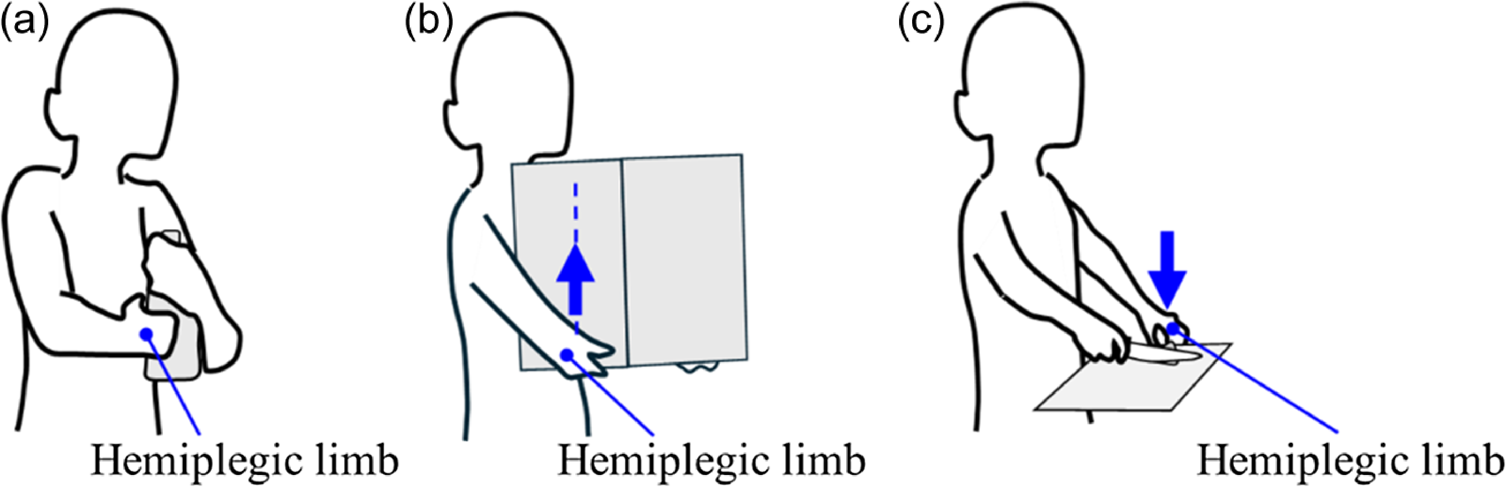
In these scenarios, the hemiplegic upper limb primarily functions as a stabilizing or supportive aid, assisting in fixing or steadying objects. Tasks such as twisting a cap or holding a knife to cut vegetables require precise coordination across multiple joints and controlled force application. Providing robotic assistance for these complex movements would necessitate multiple actuators and sensors, leading to increased weight and cost. Given these constraints, it is more practical and efficient for the non-hemiplegic upper limb to perform these complex tasks, while WELiBot supports the hemiplegic limb in a stabilizing role.
Based on the above considerations, the basic functional requirements for WELiBot are defined. First, it should provide vertical force assistance to support the hemiplegic limb. Second, it should constrain the motion of the hemiplegic limb within a predefined movement range to ensure stability and usability.
2.2. Constrained conditions
In rehabilitation therapy, two primary movements are distinguished in the evaluation and treatment process: the “reaching movement,” where the hand extends forward, and the “lifting movement,” where the hand is raised [Reference Suhaimi, Talha, Wan and Ariffin33]. In addition, movement around the trunk is important for adapting to different environments. Thus, in this study, the mechanism must be capable of producing three types of one-dimensional movements: reaching movement, lifting movement, and circumferential movement.
Previous studies on robotic systems that constrain the end-effector within a specific geometry include the work by Hou et al. [Reference Hou and Kiguchi34] and Zhang et al. [Reference Zhang, Guo and Sun35] on upper limb assistance and rehabilitation using a “virtual tunnel.” This approach employs impedance control to create a guided movement sensation, where the user’s hand follows a predefined path. The system minimizes resistance along the set path while increasing resistance perpendicular to the path to constrain motion. Higuchi et al [Reference Higuchi and Ogasawara36] developed the PAS-Arm, a human-compatible assistive arm for lifting tasks, which mechanically constrains the end-effector within a specific geometry. By using a continuously variable transmission, the robot’s joints synchronize to create a guiding plane. These robots rely on multi-joint serial mechanisms, where constraints are achieved by synchronizing joint control or mechanical design.
In this study, we propose that if a parallel mechanism can be partially decoupled with the three one-dimensional movements, a geometric constraint could be achieved by fixing one or two active joints without consuming energy. This approach eliminates the need for synchronized joint control, which is required in serial mechanisms, thereby simplifying the system’s control complexity.
2.3. Proposed mechanism
A 4R-5R parallel mechanism, shown in Figure 3, is proposed to fulfill the functional requirements under the constraints described above. An arc-shaped guide rail is attached around the human trunk, and the end-effector is connected to the hemiplegic forearm through a passive rotational arm cuff. Two sliders, Slider 1 and Slider 2, move along the arc-shaped guide rail, while the end-effector is positioned at the ends of the two chains originating from each slider.
Proposed mechanism of WELiBot.

The two chains connecting Slider 1 and Slider 2 are designated as Limb 1 and Limb 2, respectively. Since the sliders move along the arc-shaped guide rail, their motion is kinematically equivalent to a rotational joint at the center of the guide rail. The entire mechanism is represented as
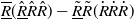 $\underline{\overline{R}}(\underline{\hat{R}}\hat{R}\hat{R})-\underline{\tilde{R}}\tilde{R}(\dot{R}\dot{R}\dot{R})$
, where the same superscript symbols indicate parallel joints, and underscored symbols denote active joints. Slider 1, Slider 2, and the rotational joint A1 serve as active joints.
$\underline{\overline{R}}(\underline{\hat{R}}\hat{R}\hat{R})-\underline{\tilde{R}}\tilde{R}(\dot{R}\dot{R}\dot{R})$
, where the same superscript symbols indicate parallel joints, and underscored symbols denote active joints. Slider 1, Slider 2, and the rotational joint A1 serve as active joints.
3. Kinematic analysis of the mechanism
3.1. Mobility analysis
Figure 4 illustrate the coordinates and denotations for the joints and links of the mechanism.
s
i,j
represents the axis vector, while
 $\hat{\textbf{S}}_{i,j}$
represents the screw, where the first subscript denotes the joint number and the second subscript denotes the limb number. The x-axis is aligned with the direction of OA1, the z-axis is aligned with the direction of
s
1,1 =
s
1,2, and the y-axis is determined based on the right-hand coordinate system. The movements of Slider 1 and Slider 2 along the guide rail are kinematically equivalent to rotational movements around the z-axis. The joints exhibit the following parallel relationship that
s
1,1 ||
s
1,2 ||
s
2,2,
s
2,1 ||
s
3,1 ||
s
4,1, and
s
3,2 ||
s
4,2 ||
s
5,2. The angle between the x-axis and OA2 is defined as
$\hat{\textbf{S}}_{i,j}$
represents the screw, where the first subscript denotes the joint number and the second subscript denotes the limb number. The x-axis is aligned with the direction of OA1, the z-axis is aligned with the direction of
s
1,1 =
s
1,2, and the y-axis is determined based on the right-hand coordinate system. The movements of Slider 1 and Slider 2 along the guide rail are kinematically equivalent to rotational movements around the z-axis. The joints exhibit the following parallel relationship that
s
1,1 ||
s
1,2 ||
s
2,2,
s
2,1 ||
s
3,1 ||
s
4,1, and
s
3,2 ||
s
4,2 ||
s
5,2. The angle between the x-axis and OA2 is defined as
 $\phi$
. The angle between OA2 and A2C2 is defined as
$\phi$
. The angle between OA2 and A2C2 is defined as
 $\psi$
.
$\psi$
.
Coordinates and denotations for the joints and links of the mechanism.

The velocity at point P on Limb 1 and Limb 2 can be expressed as:
 \begin{align} \hat{\textbf{S}}_{\textrm{P},1}&=\dot{\theta }_{1,1}\hat{\textbf{S}}_{1,1}+\dot{\theta }_{2,1}\hat{\textbf{S}}_{2,1}+\dot{\theta }_{3,1}\hat{\textbf{S}}_{3,1}+\dot{\theta }_{4,1}\hat{\textbf{S}}_{4,1} \end{align}
 \begin{align} \hat{\textbf{S}}_{\textrm{P},2}&=\dot{\theta }_{1,2}\hat{\textbf{S}}_{1,2}+\dot{\theta }_{2,2}\hat{\textbf{S}}_{2,2}+\dot{\theta }_{3,2}\hat{\textbf{S}}_{3,2}+\dot{\theta }_{4,2}\hat{\textbf{S}}_{4,2}+\dot{\theta }_{5,2}\hat{\textbf{S}}_{5,2} \end{align}
According to Figure 4, the screw representation for each joint on Limb 1 and Limb 2 is given by:
 \begin{align} \hat{\textbf{S}}_{1,1}&=\left[\begin{array}{l} {\boldsymbol{s}}_{1,1}\\ \overset{\rightharpoonup }{\textrm{OP}}\times {\boldsymbol{s}}_{1,1} \end{array}\right]=\quad \left[\begin{array}{llllll} 0 & 0 & 1 & y_{\textrm{P}}-y_{\textrm{O}} & -\left(x_{\textrm{P}}-x_{\textrm{O}}\right) & 0 \end{array}\right]^{\textrm{T}} \end{align}
 \begin{align} \hat{\textbf{S}}_{2,1}&=\left[\begin{array}{l} {\boldsymbol{s}}_{2,1}\\ \overset{\rightharpoonup }{\textrm{A}_{1}\textrm{P}}\times {\boldsymbol{s}}_{2,1} \end{array}\right]=\left[\begin{array}{llllll} 0 & 1 & 0 & -\left(z_{\textrm{P}}-z_{{\textrm{A}_{1}}}\right) & 0 & -\left(x_{\textrm{P}}-x_{{\textrm{A}_{1}}}\right) \end{array}\right]^{\textrm{T}} \end{align}
 \begin{align} \hat{\textbf{S}}_{3,1}&=\left[\begin{array}{l} {\boldsymbol{s}}_{3,1}\\ \overset{\rightharpoonup }{\textrm{B}_{1}\textrm{P}}\times {\boldsymbol{s}}_{3,1} \end{array}\right]=\left[\begin{array}{llllll} 0 & 1 & 0 & -\left(z_{\textrm{P}}-z_{{\textrm{B}_{1}}}\right) & 0 & -\left(x_{\textrm{P}}-x_{{\textrm{B}_{1}}}\right) \end{array}\right]^{\textrm{T}} \end{align}
 \begin{align} \hat{\textbf{S}}_{4,1}&=\left[\begin{array}{l} {\boldsymbol{s}}_{4,1}\\ \overset{\rightharpoonup }{\textrm{C}_{1}\textrm{P}}\times {\boldsymbol{s}}_{4,1} \end{array}\right]=\left[\begin{array}{llllll} 0 & 1 & 0 & 0 & 0 & 0 \end{array}\right]^{\textrm{T}} \end{align}
 \begin{align} \hat{\textbf{S}}_{1,2}&=\left[\begin{array}{l} {\boldsymbol{s}}_{1,2}\\ \overset{\rightharpoonup }{\textrm{OP}}\times {\boldsymbol{s}}_{1,2} \end{array}\right]=\left[\begin{array}{llllll} 0 & 0 & 1 & y_{\textrm{P}}-y_{\textrm{O}} & -\left(x_{\textrm{P}}-x_{\textrm{O}}\right) & 0 \end{array}\right]^{\textrm{T}} \end{align}
 \begin{align} \hat{\textbf{S}}_{2,2}&=\left[\begin{array}{l} {\boldsymbol{s}}_{2,2}\\ \overset{\rightharpoonup }{\textrm{A}_{2}\textrm{P}}\times {\boldsymbol{s}}_{2,2} \end{array}\right]=\left[\begin{array}{llllll} 0 & 0 & 1 & y_{\textrm{P}}-y_{{\textrm{A}_{2}}} & -\left(x_{\textrm{P}}-x_{{\textrm{A}_{2}}}\right) & 0 \end{array}\right]^{\textrm{T}} \end{align}
 \begin{align} \hat{\textbf{S}}_{3,2}&=\left[\begin{array}{l} {\boldsymbol{s}}_{3,2}\\ \overset{\rightharpoonup }{\textrm{A}_{2}\textrm{P}}\times {\boldsymbol{s}}_{3,2} \end{array}\right]=\left[\begin{array}{l} \cos \left(\varphi +\psi \right)\\ \sin \left(\varphi +\psi \right)\\ 0\\ -\left(z_{\textrm{P}}-z_{{\textrm{A}_{2}}}\right)\sin \left(\varphi +\psi \right)\\ \left(z_{\textrm{P}}-z_{{\textrm{A}_{2}}}\right)\cos \left(\varphi +\psi \right)\\ \sin \left(\varphi +\psi \right)\left(x_{\textrm{P}}-x_{{\textrm{A}_{2}}}\right)-\cos \left(\varphi +\psi \right)\left(y_{\textrm{P}}-y_{{\textrm{A}_{2}}}\right) \end{array}\right] \end{align}
 \begin{align} \hat{\textbf{S}}_{4,2}&=\left[\begin{array}{l} {\boldsymbol{s}}_{4,2}\\ \overset{\rightharpoonup }{\textrm{B}_{2}\textrm{P}}\times {\boldsymbol{s}}_{4,2} \end{array}\right]=\left[\begin{array}{l} \cos \left(\varphi +\psi \right)\\ \sin \left(\varphi +\psi \right)\\ 0\\ -\left(z_{\textrm{P}}-z_{{\textrm{B}_{2}}}\right)\sin \left(\varphi +\psi \right)\\ \left(z_{\textrm{P}}-z_{{\textrm{B}_{2}}}\right)\cos \left(\varphi +\psi \right)\\ \sin \left(\varphi +\psi \right)\left(x_{\textrm{P}}-x_{{\textrm{B}_{2}}}\right)-\cos \left(\varphi +\psi \right)\left(y_{\textrm{P}}-y_{{\textrm{B}_{2}}}\right) \end{array}\right] \end{align}
 \begin{align} \hat{\textbf{S}}_{5,2}&=\left[\begin{array}{l} {\boldsymbol{s}}_{5,2}\\ \overset{\rightharpoonup }{\textrm{C}_{2}\textrm{P}}\times {\boldsymbol{s}}_{5,2} \end{array}\right]=\left[\begin{array}{llllll} \cos \left(\varphi +\psi \right) & \sin \left(\varphi +\psi \right) & 0 & 0 & 0 & 0 \end{array}\right]^{\textrm{T}} \end{align}
The reciprocal screw can be obtained using the following equations:
 \begin{align} \left.\begin{array}{l} {\hat{\textbf{S}}^{r}}_{1,1}\circ \,\hat{\textbf{S}}_{1,1}=0\\[3pt] {\hat{\textbf{S}}^{r}}_{1,1}\circ \,\hat{\textbf{S}}_{2,1}=0\\[3pt] {\hat{\textbf{S}}^{r}}_{1,1}\circ \,\hat{\textbf{S}}_{3,1}=0\\[3pt] {\hat{\textbf{S}}^{r}}_{1,1}\circ \,\hat{\textbf{S}}_{4,1}=0 \end{array}\right\} \end{align}
 \begin{align} \left.\begin{array}{l} {\hat{\textbf{S}}^{r}}_{2,1}\circ \,\hat{\textbf{S}}_{1,1}=0\\[3pt] {\hat{\textbf{S}}^{r}}_{2,1}\circ \,\hat{\textbf{S}}_{2,1}=0\\[3pt] {\hat{\textbf{S}}^{r}}_{2,1}\circ \,\hat{\textbf{S}}_{3,1}=0\\[3pt] {\hat{\textbf{S}}^{r}}_{2,1}\circ \,\hat{\textbf{S}}_{4,1}=0 \end{array}\right\} \end{align}
 \begin{align} \left.\begin{array}{l} {\hat{\textbf{S}}^{r}}_{1,2}\circ \,\hat{\textbf{S}}_{1,2}=0\\[3pt] {\hat{\textbf{S}}^{r}}_{1,2}\circ \,\hat{\textbf{S}}_{2,2}=0\\[3pt] {\hat{\textbf{S}}^{r}}_{1,2}\circ \,\hat{\textbf{S}}_{3,2}=0\\[3pt] \begin{array}{l} {\hat{\textbf{S}}^{r}}_{1,2}\circ \,\hat{\textbf{S}}_{4,2}=0\\[3pt] {\hat{\textbf{S}}^{r}}_{1,2}\circ \,\hat{\textbf{S}}_{5,2}=0 \end{array} \end{array}\right\} \end{align}
Thus, the reciprocal screw for Limb 1 and Limb 2 is given by:
 \begin{equation} \left[\begin{array}{lll} {\hat{\textbf{S}}^{r}}_{1,1} &\quad {\hat{\textbf{S}}^{r}}_{2,1} &\quad {\hat{\textbf{S}}^{r}}_{1,2} \end{array}\right]=\left[\begin{array}{ccc} 0 &\quad 0 &\quad 0\\ 0 &\quad 1 &\quad 0\\ 0 &\quad 0 &\quad 0\\ 1 &\quad h_{1} &\quad -\sin \left(\varphi +\psi \right)\\ 0 &\quad 0 &\quad \cos \left(\varphi +\psi \right)\\ 0 &\quad x_{\textrm{P}}-x_{\textrm{O}} &\quad 0 \end{array}\right] \end{equation}
where h 1 can be assigned an arbitrary value.
The constraint matrix of the mechanism is derived by combining the reciprocal screws of both limbs:
 \begin{equation} \textbf{J}^{\prime}_{\textbf{C}}=\left[\begin{array}{l} {\hat{\textbf{S}}^{r}_{1,1}}{}^{\textrm{T}}\\[3pt] {\hat{\textbf{S}}^{r}_{2,1}}{}^{\textrm{T}}\\[3pt] {\hat{\textbf{S}}^{r}_{1,2}}{}^{\textrm{T}} \end{array}\right]=\left[\begin{array}{llllll} 0 &\quad 0 &\quad 0 &\quad 1 &\quad 0 &\quad 0\\ 0 &\quad 1 &\quad 0 &\quad h_{1} &\quad 0 &\quad x_{\textrm{P}}-x_{\textrm{O}}\\ 0 &\quad 0 &\quad 0 &\quad -\sin \left(\varphi +\psi \right) &\quad \cos \left(\varphi +\psi \right) &\quad 0 \end{array}\right] \end{equation}
By rearranging columns and applying elementary row operations, the constraint matrix can be rewritten as:
 \begin{equation} \textbf{J}_{\textbf{C}}=\left[\begin{array}{llllll} 1 &\quad 0 &\quad 0 &\quad 0 &\quad 0 &\quad 0\\ 0 &\quad 0 &\quad x_{\textrm{P}}-x_{\textrm{O}} &\quad 0 &\quad 1 &\quad 0\\ 0 &\quad 1 &\quad 0 &\quad 0 &\quad 0 &\quad 0 \end{array}\right] \end{equation}
Since the constraint forces do not perform mechanical work on the mechanism, the motion constraints are obtained as follows:
 \begin{align}& \textbf{J}_{\textbf{C}}\left[\begin{array}{l} \textbf{w}\\ \textbf{v} \end{array}\right]=\textbf{J}_{\textbf{C}}\left[\begin{array}{l} \omega _{x}\\ \omega _{y}\\ \omega _{z}\\ v_{x}\\ v_{y}\\ v_{z} \end{array}\right]=0 \end{align}
 \begin{align}& \left.\begin{array}{l} \omega _{x}=0\\ \omega _{z}\cdot \left(x_{\textrm{P}}-x_{\textrm{O}}\right)+v_{y}=0\\ \omega _{y}=0 \end{array}\right\} \end{align}
It is evident that the output link exhibits three DoF. The rotations about the x-axis and y-axis are constrained, while the angular velocity about the z-axis and translational velocity in the y-direction have a proportional relationship with the coefficient x P − x O.
As shown in Figure 5, modifying the distance between the two sliders causes the end-effector to move approximately in the radial direction with a slight change in the height, corresponding to the “reaching movement.” Rotating the active rotational joint A1 moves the end-effector in the vertical direction, corresponding to the “lifting movement.” Moving both sliders in the same direction while maintaining their relative distance results in the circumferential motion of the end-effector.
The motion of the mechanism in (a) Vertical direction, (b) Radial direction with a slight change in the height, and (c) Circumferential direction.

3.2. Displacement analysis
The coordinates, mechanism constants, and variables used for displacement analysis are defined in Figure 6. The O-XYZ coordinate system is a stationary coordinate system with its origin O at the center of the arc-shaped guide rail. The link lengths of Limb 1 are l 1,1, l 2,1, l 3,1, while those of Limb 2 are l 1,2, l 2,2, l 3,2. The angular displacement of Slider 1 and Slider 2 relative to the X-axis on the XY-plane is given by θ 1,1 and θ 2,1. The angular displacement of joint A1 relative to the XY-plane is given by θ 2,1.
The coordinates, mechanism constants, and variables for displacement analysis: (a) Mechanism in 3-Dimensions, (b) Projection of the mechanism onto the XY-plane, and (c) Projection of the mechanism onto the uZ- plane.

Figure 6b shows a projection of the mechanism onto the XY-plane, viewed from the positive Z-axis direction. The angle between OC1 and A2C2 is denoted as
 $\alpha$
. The position of the end-effector P is defined as the intersection of the line passing through C1, perpendicular to OC1, and the line passing through C2, perpendicular to A2C2. The distance between P to A2C2, as well as OC1, is presented as l
e. Point Q is the intersection of the extended line of OC1 and A2C2. A new u-axis is defined along OC1 in Figure 6b, allowing Limb 1 to be described in the uZ-plane, as shown in Figure 6c. The projection of point P on the u-axis is designated as point R.
$\alpha$
. The position of the end-effector P is defined as the intersection of the line passing through C1, perpendicular to OC1, and the line passing through C2, perpendicular to A2C2. The distance between P to A2C2, as well as OC1, is presented as l
e. Point Q is the intersection of the extended line of OC1 and A2C2. A new u-axis is defined along OC1 in Figure 6b, allowing Limb 1 to be described in the uZ-plane, as shown in Figure 6c. The projection of point P on the u-axis is designated as point R.
For simplicity, interference between the mechanism components, and interference between the mechanism and the human body are neglected in the following calculations.
3.2.1. Forward displacement analysis
In forward displacement analysis, the position of the end-effector P(X P, Y P, Z P) is determined based on the displacements of the active joints θ 1,1, θ 2,1, and θ 1,2.
First, the XY-coordinates of point P are considered. The coordinates of point Q(X Q, Y Q) in Figure 6b can be calculated as follows:
 \begin{equation} \left.\begin{array}{l} X_{\textrm{Q}}=\dfrac{l_{1,2}\sin \theta _{1,2}-l_{1,2}\cos \theta _{1,2}\tan \left(\theta _{1,1}-\alpha \right)}{\tan \theta _{1,1}-\tan \left(\theta _{1,1}-\alpha \right)}\\ Y_{\textrm{Q}}=\tan \theta _{1,1}\cdot X_{\textrm{Q}} \end{array}\right\} \end{equation}
Using X Q and Y Q, the XY-coordinates of point P(X P, Y P) are expressed as:
 \begin{equation} \left.\begin{array}{l} X_{\textrm{P}}=X_{\textrm{Q}}-\dfrac{l_{\textrm{e}}}{\sin \frac{\alpha }{2}}\cos \left(\theta _{1,1}-\dfrac{\alpha }{2}\right)\\[5pt] Y_{\textrm{P}}=Y_{\textrm{Q}}-\dfrac{l_{\textrm{e}}}{\sin \frac{\alpha }{2}}\sin \left(\theta _{1,1}-\dfrac{\alpha }{2}\right) \end{array}\right\} \end{equation}
Next, the Z-coordinate of point P is determined. In Figure 6c, Z P can be calculated as the intersection between a circle with a radius of l 3,1 centered at point B1 and the line u = u P:
 \begin{equation} Z_{\textrm{P}}=\sqrt{{l_{3,1}}^{2}-\left(u_{\textrm{P}}-u_{\textrm{B},1}\right)^{2}}+Z_{\textrm{B},1} \end{equation}
where
 \begin{equation} \left.\begin{array}{l} u_{\textrm{P}}=\textrm{OR}=\sqrt{{x_{\textrm{P}}}^{2}+{y_{\textrm{P}}}^{2}}\cos \left\{\tan ^{-1}\left(\dfrac{y_{\textrm{P}}}{x_{\textrm{P}}}\right)-\theta _{1,1}\right\}\\ u_{\textrm{B},1}=l_{1,1}+l_{2,1}\cos \theta _{2,1}\\ Z_{\textrm{B},1}=l_{2,1}\sin \theta _{2,1} \end{array}\right\} \end{equation}
3.2.2. Inverse displacement analysis
In inverse displacement analysis, the displacements of the active joints θ 1,1, θ 2,1, and θ 1,2 are determined based on the position of the end-effector (X P, Y P, Z P).
The angular displacement θ 1,1 and θ 1,2 of Slider 1 and Slider 2 can be calculated using X P and Y P.
 \begin{equation} \theta _{1,1}=\tan ^{-1}\left(\frac{X_{\textrm{P}}}{Y_{\textrm{P}}}\right)-\sin ^{-1}\left(\frac{l_{\textrm{e}}}{\sqrt{{X_{P}}^{2}+{Y_{P}}^{2}}}\right) \end{equation}
Using the calculated θ 1,1, the coordinates of point Q(X Q, Y Q) can be expressed as follows:
 \begin{equation} \left.\begin{array}{l} X_{\textrm{Q}}=X_{\textrm{P}}+\dfrac{l_{\textrm{e}}}{\sin \frac{\alpha }{2}}\cos \left(\theta _{1,1}-\dfrac{\alpha }{2}\right)\\ Y_{\textrm{Q}}=X_{\textrm{P}}+\dfrac{l_{\textrm{e}}}{\sin \frac{\alpha }{2}}\sin \left(\theta _{1,1}-\dfrac{\alpha }{2}\right) \end{array}\right\} \end{equation}
The value of θ 1,2 is determined as follows:
 \begin{equation} \theta _{1,2}=\pm \cos ^{-1}\left\{\frac{Y_{\textrm{Q}}\cos \left(\theta _{1,1}-\alpha \right)-X_{\textrm{Q}}\sin \left(\theta _{1,1}-\alpha \right)}{l_{1,2}}\right\}+\left(\theta _{1,1}-\alpha +\frac{\pi }{2}\right) \end{equation}
From the sign of the first term on the right-hand side, it is evident that the inverse kinematic solution for
 $\theta\!$
1,2 has two possible values. The positive solution results in link A2B2 being positioned inside the arc-shaped guide rail, which is unsuitable. Therefore, the negative solution is selected for the subsequent analysis. The value of θ
2,1 can be calculated as follows, based on Figure 6c.
$\theta\!$
1,2 has two possible values. The positive solution results in link A2B2 being positioned inside the arc-shaped guide rail, which is unsuitable. Therefore, the negative solution is selected for the subsequent analysis. The value of θ
2,1 can be calculated as follows, based on Figure 6c.
 \begin{equation} \theta _{2,1}=\angle \textrm{PA}_{1}\textrm{R}-\angle \textrm{PA}_{1}\textrm{B}_{1}=\tan ^{-1}\left(\frac{Z_{\textrm{P}}}{u_{\textrm{AR}}}\right)-\cos ^{-1}\left(\frac{{u_{\textrm{AR}}}^{2}+{Z_{\textrm{P}}}^{2}+{l_{2,1}}^{2}-{l_{3,1}}^{2}}{2l_{2,1}\sqrt{{u_{\textrm{AR}}}^{2}+{Z_{\textrm{P}}}^{2}}}\right) \end{equation}
where
 \begin{equation} u_{\textrm{AR}}=\textrm{A}_{1}\textrm{R}=\sqrt{{X_{\textrm{P}}}^{2}+{Y_{\textrm{P}}}^{2}}\cos \left\{\tan ^{-1}\left(\frac{Y_{P}}{X_{P}}\right)-\theta _{1,1}\right\}-l_{1,1} \end{equation}
3.3. Workspace analysis
Similar to the displacement analysis, interference between the mechanism’s joints and links, as well as interference between the mechanism and the human body, are neglected in this study. In addition, the constraint
 $\theta\!$
1,1 <
$\theta\!$
1,1 <
 $\theta\!$
1,2 is applied to the sliders since the two sliders cannot pass each other. In practice, two sliders contact each other at a certain angular difference. For this analysis, however, the sliders are theoretically treated as points.
$\theta\!$
1,2 is applied to the sliders since the two sliders cannot pass each other. In practice, two sliders contact each other at a certain angular difference. For this analysis, however, the sliders are theoretically treated as points.
Since the XY-coordinates (X
P, Y
P) of the end-effector are determined solely by the slider positions
 $\theta\!$
1,1 and
$\theta\!$
1,1 and
 $\theta\!$
1,2, the workspace of the mechanism is analyzed in the XY-plane and Z-coordinate, respectively. Let r
P represent the distance between the origin point O and the end-effector P, with its maximum and minimum values denoted as r
P,max, r
P,min, respectively.
$\theta\!$
1,2, the workspace of the mechanism is analyzed in the XY-plane and Z-coordinate, respectively. Let r
P represent the distance between the origin point O and the end-effector P, with its maximum and minimum values denoted as r
P,max, r
P,min, respectively.
This can be analytically derived based on the results of the displacement analysis. In Figure 6b, the shape of the quadrilateral PC1QC2 remains constant, regardless of
 $\theta\!$
1,1 and
$\theta\!$
1,1 and
 $\theta\!$
1,2. Therefore, when the distance r
Q between the origin point O and point Q reaches its maximum or minimum value, the distance r
P also takes its respective maximum or minimum value. Moreover, since the mechanism is symmetric about the Z-axis, when evaluating the maximum and minimum values of r
Q,
$\theta\!$
1,2. Therefore, when the distance r
Q between the origin point O and point Q reaches its maximum or minimum value, the distance r
P also takes its respective maximum or minimum value. Moreover, since the mechanism is symmetric about the Z-axis, when evaluating the maximum and minimum values of r
Q,
 $\theta\!$
1,1 can be fixed at 0, and only
$\theta\!$
1,1 can be fixed at 0, and only
 $\theta\!$
1,2 is considered as a variable. By substituting
$\theta\!$
1,2 is considered as a variable. By substituting
 $\theta\!$
1,1 = 0 into Eq. (20), we obtain the Eq. (29):
$\theta\!$
1,1 = 0 into Eq. (20), we obtain the Eq. (29):
 \begin{equation} \left.\begin{array}{l} X_{\textrm{Q}}=\dfrac{l_{1,2}}{\sin \alpha }\left(\cos \alpha \sin \theta _{1,2}+\sin \alpha \cos \theta _{1,2}\right)=\dfrac{l_{1,2}}{\sin \alpha }\cdot \sin \left(\theta _{1,2}+\alpha \right)\\ Y_{\textrm{Q}}=0 \end{array}\right\} \end{equation}
so that,
 \begin{equation} r_{\textrm{Q}}=\sqrt{{X_{\textrm{Q}}}^{2}+{Y_{\textrm{Q}}}^{2}}=\frac{l_{1,2}}{\sin \alpha }\cdot \sin \left(\theta _{1,2}+\alpha \right) \end{equation}
Therefore, r
Q reaches its maximum value when the term sin(
 $\theta\!$
1,2+
$\theta\!$
1,2+
 $\alpha$
) on the right-hand side reaches its maximum value, satisfying OA2⊥A2C2:
$\alpha$
) on the right-hand side reaches its maximum value, satisfying OA2⊥A2C2:
 \begin{equation} \theta _{1,2}=\frac{\pi }{2}-\alpha \end{equation}
Similarly, r
Q reaches its minimum value when sin(
 $\theta\!$
1,2+
$\theta\!$
1,2+
 $\alpha$
) takes its minimum value. Since sin(
$\alpha$
) takes its minimum value. Since sin(
 $\theta\!$
1,2+
$\theta\!$
1,2+
 $\alpha$
) increases monotonically within the range 0 ≤
$\alpha$
) increases monotonically within the range 0 ≤
 $\theta\!$
1,2 ≤ π/2-
$\theta\!$
1,2 ≤ π/2-
 $\alpha$
, its minimum value occurs when
$\alpha$
, its minimum value occurs when
 $\theta\!$
1,2 = 0. Therefore, r
P = r
P,min occurs when
$\theta\!$
1,2 = 0. Therefore, r
P = r
P,min occurs when
 $\theta\!$
1,1 =
$\theta\!$
1,1 =
 $\theta\!$
1,2.
$\theta\!$
1,2.
Based on this, r P,max and r P,min can be determined as follows:
 \begin{equation} \begin{array}{l} \left.\begin{array}{l} r_{\textrm{P},\max }=\sqrt{\left(\dfrac{l_{1,2}}{\sin \alpha }-\dfrac{l_{e}}{\tan \left(\alpha /2\right)}\right)^{2}+{l_{e}}^{2}}\left(when\,\theta _{1,2}=\theta _{1,1}+\dfrac{\pi }{2}-\alpha \right)\\ r_{\textrm{P},\min }=\sqrt{\left(l_{1,2}-\dfrac{l_{e}}{\tan \left(\alpha /2\right)}\right)^{2}+{l_{e}}^{2}}\left(when\,\theta _{1,1}=\theta _{1,2}\right) \end{array}\right\}\\ \end{array} \end{equation}
The workspace in the XY-plane is represented as a doughnut-shaped region, indicated by the gray area in Figure 7a.
The workspace of the mechanism in (a) XY-plane and (b) Z-axis direction.

Next, the maximum value Z P,max and minimum value Z P,min are determined, given values of X P and Y P. First, consider only Limb 1. Figure 7b represents Limb 1 in the uZ-plane. Z P reaches its maximum value Z P,max,1 or minimum value Z P,min, when points A1, B1, and C1 are aligned in a straight line. Therefore, Z P,max,1 and Z P,min,1 can be expressed as follows:
 \begin{equation} \begin{array}{l} Z_{\textrm{P},\max ,1}=\sqrt{\left(l_{2,1}+l_{3,1}\right)^{2}-{u_{\textrm{AR}}}^{2}}\\ Z_{P,\min ,1}=-Z_{\textrm{P},\max ,1}=-\sqrt{\left(l_{2,1}+l_{3,1}\right)^{2}-{u_{\textrm{AR}}}^{2}} \end{array} \end{equation}
The value of u AR can be determined using (28).
Similarly, considering only Limb 2, Figure 7c represents Limb 2 in the vZ 2-plane, where the Z 2-axis is defined as the line parallel to the Z-axis, passing through point A2, and the v-axis corresponds to the A2C2 direction as shown in Figure 6b. For Limb 2, Z P reaches its maximum value Z P,max,2 or minimum value Z P,min,2 when points A2, B2, and C2 are aligned in a straight line. Therefore, Z P,max,2 and Z P,min,2 can be expressed as follows:
 \begin{equation} \begin{array}{l} \left.\begin{array}{l} Z_{\textrm{P},\max ,2}=\sqrt{\left(l_{2,2}+l_{3,2}\right)^{2}-{v_{\textrm{AS}}}^{2}}\\ Z_{\textrm{P},\min ,2}=-Z_{\textrm{P},\max ,2}=-\sqrt{\left(l_{2,2}+l_{3,2}\right)^{2}-{v_{\textrm{AS}}}^{2}} \end{array}\right\}\\ \end{array} \end{equation}
where
 \begin{equation} v_{\textrm{AS}}=\sqrt{\left\{x_{\textrm{P}}-l_{e}\sin \left(\theta _{1,1}-\alpha \right)-l_{1,2}\cos \theta _{1,2}\right\}^{2}+\left\{y_{\textrm{P}}+l_{e}\cos \left(\theta _{1,1}-\alpha \right)-l_{1,2}\sin \theta _{1,2}\right\}^{2}} \end{equation}
Based on this, considering both Limb 1 and Limb 2, Z P,max is constrained by the smaller value between Z P,max,1 and Z P,max,2, while Z P,min is constrained by the larger value between ZP,min,1 and ZP,min,2. Therefore, Z P,max and Z P,min can be expressed as follows:
 \begin{equation} \left.\begin{array}{l} Z_{\textrm{P},\max }=\min \left(Z_{\textrm{P},\max ,1},\,Z_{\textrm{P},\max ,2}\right)\\ Z_{\textrm{P},\min }=\max \left(Z_{\textrm{P},\min ,1},\,Z_{\textrm{P},\min ,2}\right) \end{array}\right\} \end{equation}
In addition, the end-effector cannot reach within a circular region centered at A1 of Limb1 and A2 of Limb2, with radii r = ∣l 2,1−l 3,1∣ and r = ∣ l 2,2−l 3,2∣, respectively. Therefore, these regions must be excluded from the workspace.
Based on the above analysis, the workspace in three-dimensional space can be determined by obtaining the boundary of the workspace from the XY-plane and the Z-axis direction while excluding the unreachable regions. Since the mechanism is symmetric about the Z-axis, the three-dimensional workspace can be obtained by rotating the XZ plane workspace 360° around the Z-axis.
4. Static analysis
The mechanism consists of seven links, excluding the fixed circular guide rail. First, the equations of force and moment equilibrium are established for each of the seven segments, as illustrated in Figure 8.
Free body diagram of the mechanism.

Let F i and M i represent the force and moment acting on each link, respectively. The mass of each link is denoted as m i , and the center of mass is represented by the position vector G i . The distance between the origin O and each slider is denoted as r i , while the length of each link is l i . g represents the gravitational acceleration. The equilibrium equations of force and moment acting on the links are expressed as follows:
 \begin{equation} \left.\begin{array}{c} {\boldsymbol{F}}_{\textrm{S}1}-{\boldsymbol{F}}_{\textrm{A}1}+m_{\textrm{SA},1}{\boldsymbol{g}}=0\\ {\boldsymbol{M}}_{\textrm{S}1}-{\boldsymbol{M}}_{\textrm{A}1}+\left\{\left(\textrm{A}_{1}-\textrm{S}_{1}\right)\times \left(-{\boldsymbol{F}}_{\textrm{A}1}\right)\right\}+\left\{\left(\textrm{G}_{\textrm{SA},1}-\textrm{S}_{1}\right)\times m_{\textrm{SA},1}{\boldsymbol{g}}\right\}=0 \end{array}\right\} \end{equation}
 \begin{equation} \left.\begin{array}{c} {\boldsymbol{F}}_{\textrm{A}1}-{\boldsymbol{F}}_{\textrm{B}1}+m_{\textrm{AB},1}{\boldsymbol{g}}=0\\ {\boldsymbol{M}}_{\textrm{A}1}-{\boldsymbol{M}}_{\textrm{B}1}+\left\{\left(\textrm{B}_{1}-\textrm{A}_{1}\right)\times \left(-{\boldsymbol{F}}_{\textrm{B}1}\right)\right\}+\left\{\left(\textrm{G}_{\textrm{AB},1}-\textrm{A}_{1}\right)\times m_{\textrm{AB},1}{\boldsymbol{g}}\right\}=0 \end{array}\right\} \end{equation}
 \begin{equation} \left.\begin{array}{c} {\boldsymbol{F}}_{\textrm{B}1}-{\boldsymbol{F}}_{\textrm{C}1}+m_{BC,1}{\boldsymbol{g}}=0\\ {\boldsymbol{M}}_{\textrm{B}1}-{\boldsymbol{M}}_{\textrm{C}1}+\left\{\left(C_{1}-B_{1}\right)\times \left(-{\boldsymbol{F}}_{\textrm{C}1}\right)\right\}+\left\{\left({\boldsymbol{G}}_{\textrm{BC},1}-B_{1}\right)\times m_{\textrm{BC},1}{\boldsymbol{g}}\right\}=0 \end{array}\right\} \end{equation}
 \begin{equation} \left.\begin{array}{c} {\boldsymbol{F}}_{\textrm{S}2}-{\boldsymbol{F}}_{\textrm{A}2}+m_{\textrm{SA},2}{\boldsymbol{g}}=0\\ {\boldsymbol{M}}_{\textrm{S}2}-{\boldsymbol{M}}_{\textrm{A}2}+\left\{\left(\textrm{A}_{2}-\textrm{S}_{2}\right)\times \left(-{\boldsymbol{F}}_{\textrm{A}2}\right)\right\}+\left\{\left(\textrm{G}_{\textrm{SA},2}-\textrm{S}_{2}\right)\times m_{\textrm{SA},2}{\boldsymbol{g}}\right\}=0 \end{array}\right\} \end{equation}
 \begin{equation} \left.\begin{array}{c} {\boldsymbol{F}}_{\textrm{A}2}-{\boldsymbol{F}}_{\textrm{B}2}+m_{\textrm{AB},2}{\boldsymbol{g}}=0\\ {\boldsymbol{M}}_{\textrm{A}2}-{\boldsymbol{M}}_{\textrm{B}2}+\left\{\left(\textrm{B}_{2}-\textrm{A}_{2}\right)\times \left(-{\boldsymbol{F}}_{\textrm{B}2}\right)\right\}+\left\{\left(\textrm{G}_{\textrm{AB},2}-\textrm{A}_{2}\right)\times m_{\textrm{AB},2}{\boldsymbol{g}}\right\}=0 \end{array}\right\} \end{equation}
 \begin{equation} \left.\begin{array}{c} {\boldsymbol{F}}_{\textrm{B}2}-{\boldsymbol{F}}_{\textrm{C}2}+m_{\textrm{BC},2}{\boldsymbol{g}}=0\\ {\boldsymbol{M}}_{\textrm{B}2}-{\boldsymbol{M}}_{\textrm{C}2}+\left\{\left(C_{2}-B_{2}\right)\times \left(-{\boldsymbol{F}}_{\textrm{C}2}\right)\right\}+\left\{\left({\boldsymbol{G}}_{\textrm{BC},2}-B_{2}\right)\times m_{\textrm{BC},2}{\boldsymbol{g}}\right\}=0 \end{array}\right\} \end{equation}
 \begin{equation} \left.\begin{array}{c} {\boldsymbol{F}}_{\textrm{C}1}+{\boldsymbol{F}}_{\textrm{C}2}+{\boldsymbol{F}}_{E}+m_{E}{\boldsymbol{g}}=0\\ {\boldsymbol{M}}_{\textrm{C}1}+{\boldsymbol{M}}_{\textrm{C}2}\boldsymbol{+}{\boldsymbol{M}}_{\textrm{E}}+\left\{\left(C_{2}-C_{1}\right)\times \left({\boldsymbol{F}}_{\textrm{C}2}\right)\right\}+\left\{\left({\boldsymbol{P}}-{\boldsymbol{C}}_{1}\right)\times \left({\boldsymbol{F}}_{\textrm{E}}+m_{\textrm{E}}{\boldsymbol{g}}\right)\right\}=0 \end{array}\right\} \end{equation}
In addition to these equilibrium equations, the condition that the moment around the axis of each passive revolute joint (B1, C1, A2, B2, and C2 ) is zero is applied:
 \begin{equation} \left.\begin{array}{l} {\boldsymbol{s}}_{3,1}\cdot {\boldsymbol{M}}_{\textrm{B}1}=0\\ {\boldsymbol{s}}_{4,1}\cdot {\boldsymbol{M}}_{\textrm{C}1}=0\\ {\boldsymbol{s}}_{2,2}\cdot {\boldsymbol{M}}_{\textrm{A}2}=0\\ {\boldsymbol{s}}_{3,2}\cdot {\boldsymbol{M}}_{\textrm{A}2}=0\\ {\boldsymbol{s}}_{4,2}\cdot {\boldsymbol{M}}_{\textrm{B}2}=0\\ {\boldsymbol{s}}_{5,2}\cdot {\boldsymbol{M}}_{\textrm{C}2}=0 \end{array}\right\} \end{equation}
Given that the position vectors of the joints and centers of mass, the segment masses, and the external forces and moments acting on the end-effector are known, the number of unknown joint forces and moments matches the number of equations, both being 48. Therefore, Eqs. (37) to (44) are solvable.
5. Prototype
A prototype was fabricated to evaluate the effectiveness of motion assistance through experiments involving upper limb attachment. Figure 9 shows a photograph of the developed prototype, and Table I lists the mechanism parameters. In this study, the prototype was not intended for actual attachment to the body or practical application. It was for verifying the mechanical feasibility and baseline assistive performance. Therefore, the circular guide rail was designed as an arc with a central angle of 90 degrees and was fixed to a stand. Aluminum was used as the primary material for most parts, while carbon fiber-reinforced nylon (Onyx), produced using a 3D printer, was used for the arm cuff and some simple spacers. The weight of the prototype was around 3.9 kg.
The fabricated prototype: (a) Configuration of the prototype (b) Prototype attached to the human arm.

Figure 10a shows the structure of the circular guide rail. The radial cross-section has an H-shape with 45-degree inclined surfaces. A flexible rack from Kohara Gear Industry Co., Ltd. is fixed to the outer surface of the guide rail. Figure 10b and 10c show the structure of Slider 1 and Slider 2, respectively. The roller structure is common to both sides, as illustrated in Figure 10e. The rollers are mounted at a 45-degree tilt so that they contact the inclined surfaces of the circular guide rail. Roller tighten screws allow the rollers to be pressed against the guide rail by adjusting the screws in the direction of the blue arrow. Figure 10d shows the end-effector and arm cuff components. The arm cuff includes two passive revolute joints around the axes indicated by the black dashed lines. Rotational motion around the axis shown by the red dashed line is accommodated by slippage between the arm cuff and the forearm or between the forearm and clothing. For simplicity, these rotations were not incorporated into the mechanism as revolute joints. The prototype also included several design features for safety. Mechanical stoppers were mounted at both ends of the arc-shaped guide rail to prevent the sliders from detaching during operation. An emergency stop button was positioned at the end of the guide, allowing immediate interruption of motion if necessary. The arm cuff was equipped with passive rotational joints to reduce the risk of excessive torque on the user’s arm, and a Velcro fastening tape was used to enable quick detachment when needed.
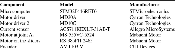
Figure 11 shows the circuit configuration of the prototype, and Table II lists the model numbers of the major components. The motor power supply was provided externally using a 12V DC stabilized power source.
Parameters of the prototype.

The configuration of the prototype: (a) arc-shape guide rail (b) Slider 1 (c) Slider 2 (d) Arm cuff (e) Rollers and the tighten screw.

The circuit configuration.

Main components of the prototype.
6. Experiments
To evaluate the concept and assistance performance of WELiBot, experiments were conducted with four healthy participants (age: 26 ± 4.5, weight: 65 ± 8.2 kg, height: 172 ± 7.6 cm) to analyze the differences in muscle activity levels under two conditions: with and without robotic assistance. Each participant repeated the specified motion five times, and the muscle activities of the anterior deltoid, biceps brachii, and infraspinatus were measured using electromyography (EMG) sensors (Biometrics, UK).
In addition to EMG analysis, a motion measurement experiment was conducted to assess the displacements of WELiBot quantitatively. Four representative upper limb movements were performed: circumferential, raising, reaching forward, and a combined motion of the first three. Each motion was executed five times without the participants, and the relative displacements Δx, Δy, and Δz of the end-effector (endpoint minus starting point) were recorded using an OptiTrack (NaturalPoint, Inc., USA) motion capture system.
6.1. Experimental setup
In both the assistance experiment and the motion measurement, the arm cuff of the robot was moved along a straight trajectory with PD control, following a trapezoidal acceleration and deceleration profile with an acceleration of a = 0.5 m/s2 and a maximum velocity of v
max = 0.3 m/s. The total motion time was about 1.67 s. Muscle activity measurements and the robot’s motion were synchronized using a trigger switch (Biometrics Ltd, UK). The block diagram of the controller is shown in Figure 12. In the block diagram,
 ${\boldsymbol{x}}_{d}$
is the target trajectory of the end-effector, and
${\boldsymbol{x}}_{d}$
is the target trajectory of the end-effector, and
 $\boldsymbol{\theta }_{d}$
and
$\boldsymbol{\theta }_{d}$
and
 $\boldsymbol{\theta }_{a}$
indicate the target angle and measured angle of each active joint, respectively.
$\boldsymbol{\theta }_{a}$
indicate the target angle and measured angle of each active joint, respectively.
 $\dot{{\boldsymbol{x}}}_{d}$
and
$\dot{{\boldsymbol{x}}}_{d}$
and
 $\dot{\boldsymbol{\theta }}_{d}$
are the corresponding velocity and angular velocity.
$\dot{\boldsymbol{\theta }}_{d}$
are the corresponding velocity and angular velocity.
 ${\boldsymbol{V}}$
is the driving voltage.
${\boldsymbol{V}}$
is the driving voltage.
 ${\boldsymbol{F}}_{\textit{assist}}$
is the assistive force.
${\boldsymbol{F}}_{\textit{assist}}$
is the assistive force.
 ${\boldsymbol{K}}_{p}$
and
${\boldsymbol{K}}_{p}$
and
 ${\boldsymbol{K}}_{d}$
are the proportional gain and derivative gain, respectively.
${\boldsymbol{K}}_{d}$
are the proportional gain and derivative gain, respectively.
 ${\boldsymbol{s}}$
is the Laplace variable.
${\boldsymbol{s}}$
is the Laplace variable.
The block diagram of the PD controller.

In the condition without robot assistance, participants were instructed to move their arms along the same trajectory as in the robot-assisted condition, maintaining the same start and end positions. The motion was guided by a metronome, set at a beat interval of 60/72 s. The specific motion was performed over two beats, ensuring consistency with the robot-assistance condition.
6.2. Results of muscle activity
In the assistance experiment, the specified motion involved a straight-line movement from the position at (0.24, 0.32, 0) to (0.1, 0.37, 0.30) (m) in the coordinate shown in Figure 9a. This motion simulates the daily task of picking up an object from a table and holding it in a static position. Figure 9b shows an example of the experimental setup with robot assistance.
The EMG voltage V EMG(t) at each moment was computed from the raw EMG data e(t) using the following formula, with a window length T = 300 ms:
 \begin{equation} V_{\textrm{EMG}}\left(t\right)=\sqrt{\frac{1}{T}\int _{-T/2}^{T/2}e^{2}\left(t+\tau \right)d\tau } \end{equation}
This process was performed for each of the five trials under the same conditions, and the average V EMG(t) across the trials is shown in Figure 13. Moreover, the mean absolute value (MAV) of V EMG(t) was calculated over the entire duration of 1.67 s, representing the overall muscle activity for each trial. An independent two-tailed t-test has been conducted to compare the difference in conditions with and without robot assistance. The results shown in Figure 14 indicate that the muscle activities of the infraspinatus, anterior deltoid, and biceps brachii were reduced in the robot-assistance condition, confirming the effectiveness of assistance. In particular, for all four subjects, the biceps brachii muscle activity was significantly decreased.
RMS from four subjects under the condition with and without robot assistance.

Comparison of EMG data from four subjects.

6.3. Results of measured end-effector displacement
The measured coordinates of the starting and endpoint for each motion are summarized in Table III.
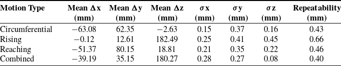
The standard deviations of relative displacement along the x, y, and z axes (σ x , σ y , σ z ) were computed, and a 3D repeatability radius was defined as:
 \begin{equation} R=\sqrt{{\sigma _{x}}^{2}+{\sigma _{y}}^{2}+{\sigma _{z}}^{2}} \end{equation}
Table IV presents the mean displacement, standard deviations, and repeatability results for the four motions.
The repeatability was 0.43 mm for circumferential motion, 0.66 mm for rising motion, 0.46 mm for reaching motion, and 0.40 mm for combined motion. These results indicate that WELiBot consistently reproduced similar motion displacements across repeated motion tasks, demonstrating stable and reliable actuation performance.
7. Discussion
The experimental results demonstrated that WELiBot effectively reduced muscle activity, particularly in the biceps brachii, confirming its potential for upper limb assistance. The displacement measurement shows that robots can realize reliable actuation performance. Despite its effectiveness, this study has several limitations related to both analysis and experimental setup.
One major limitation of the present study lies in the experimental participants. The intended users of WELiBot are individuals with hemiplegia. However, the current study was conducted with healthy individuals, which does not fully reflect the challenges faced by individuals with upper limb impairments. To develop an assistive device truly suitable for hemiplegic upper limb rehabilitation, WELiBot is expected to improve in the following three directions. First, the current prototype is fixed on a stand and is not wearable. For a user with limb impairment, the robot must prioritize lightweight construction, ease of attachment and removal, and minimal setup burden, ideally allowing the user to wear the system independently or with minimal assistance from a caregiver. Second, an appropriate control strategy for WELiBot is needed. The symptoms and movement patterns of patients with hemiplegia vary significantly across individuals. Therefore, the robot is expected to incorporate adaptive control strategies, such as impedance control, EMG-based control [Reference Pons, Ceres, Rocon, Levin, Markovitz, Saro, Reynaerts, Van Moorleghem and Bueno37], or Assist-As-Needed (AAN) frameworks [Reference Zhang, Zeng, Li, Xu, Li and Song38]. These approaches aim to assist each user according to their residual function and promote active use of the affected limb, which is considered critical in enhancing neuroplasticity and functional recovery. Third, the WELiBot design utilized passive rotational joints in the arm cuff to enhance safety for subject experiments. Nevertheless, therapists have pointed out that such passive mechanisms may not provide adequate support for patients with muscle spasticity or joint stiffness, which are common in hemiplegia. During upper limb rehabilitation, therapists typically stabilize the patient’s wrist manually to facilitate movement at the shoulder and elbow. Hence, future iterations of WELiBot should include a redesigned wrist interface that provides secure, adjustable, and clinically informed support tailored to hemiparetic conditions. In addition, further studies involving a larger sample size and participants with upper limb impairments are necessary to validate the effectiveness of WELiBot in real-world ADL scenarios.
In terms of kinematic and static analysis, the study did not account for direct interactions between the robot and the human body. Since WELiBot is designed as a wearable device to assist with ADLs in individuals with motor impairments, the current prototype does not fully address practical challenges associated with real-world use. In addition, the workspace analysis was based on geometric constraints, without incorporating human anatomical factors, such as joint range of motion and individual movement variability. These factors may influence the robot’s effectiveness and usability and should be integrated into future design considerations.
Measured coordinates of the starting point and the endpoint.

Measured end-effector displacement.
Regarding the experimental setup, the prototype was not attached to the body, as the guide rail was fixed to a stationary stand, and only one-quarter of the rail was fabricated. This limited the assessment of the robot’s full motion range and usability. Attaching the guide rail directly to the human body may introduce additional constraints, dynamic interactions, and comfort-related factors, which require further investigation. In addition, the experiment was limited to a predefined straight-line motion, constrained by the workspace range of the fabricated prototype. Future studies should investigate the WELiBot’s performance with a full-scale prototype.
While a fully wearable version of WELiBot remains a long-term objective, alternative configurations such as a frame-mounted or semi-mobile system may be more practical for some users, especially elderly individuals or those with severe hemiplegia, because such users may face difficulties tolerating wearable systems. A fixed-stand configuration, when properly designed, can still provide meaningful motion assistance while improving usability and safety. This design consideration is also worth exploring further in future development stages to balance functionality with accessibility in rehabilitation applications.
8. Conclusion
This study mainly introduced the design of WELiBot, a novel wearable end-effector-type upper limb assistive robot designed to provide effective support for individuals with upper limb motor impairments. The research began with the conception of robot design, defining its functional requirements and mechanical structure. A 4R-5R parallel mechanism was developed to enable controlled assistance in lifting, reaching, and circumferential motions while ensuring ease of attachment and portability. Kinematic and workspace analyses confirmed that the mechanism provides a well-defined, toroidal workspace centered around the user’s torso, meeting motion assistance requirements. In addition, static analysis provided insights into force distribution, aiding in the selection of design parameters. To assess mechanical feasibility, a prototype with a quarter arc-shaped guide rail was fabricated and tested. Muscle activity experiments conducted with four healthy participants demonstrated a significant reduction in biceps brachii muscle activity compared to unassisted movement, confirming WELiBot’s effectiveness in reducing physical effort. Future research will focus on attaching the guide rail to the body to improve usability, refining the control strategy for enhanced motion assistance, and conducting further daily task-based experiments to evaluate the robot’s real-world effectiveness.
Acknowledgements
This research is an extended version of the conference paper “Design and Preliminary Testing of WELiBot: A Wearable End-Effector Type Upper Limb Assistive Robot,” published in Mechanisms and Machine Science, doi:10.1007/978-3-031-64569-3_9.
Author contributions
Ming Jiang and Ryohei Morita contributed to study methodology, investigation, software development, data curation, visualization, manuscript drafting, review, and editing. Yang Wang and Takashi Shinoda contributed to study methodology, investigation, software development, data curation, and manuscript review and editing. Qizhi Meng, Andrea Botta, Giuseppe Quaglia, and Marco Ceccarelli provided insights into the methodology, mechanical design workspace analysis, and manuscript review and editing. Yukio Takeda supervised the study, oversaw the study methodology, facilitated resource acquisition, and contributed to manuscript review and editing.
Financial support
This work was partly supported by the Mizuho Foundation for the Promotion of Sciences and the Fujikura Foundation.
Competing interests
The authors declare no conflicts of interest exist.
Ethical approval
All experiments in this study were conducted following the Ethical Guidelines for Life Science and Medical Research Involving Human Subjects. The protocol for this research received approval from the Human Subjects Research Ethics Review Committee of the Institute of Science Tokyo, approval number 2024204.
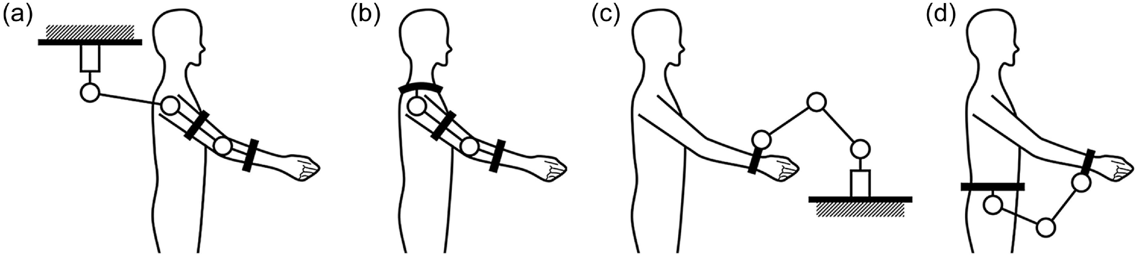

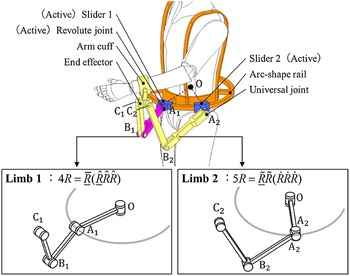
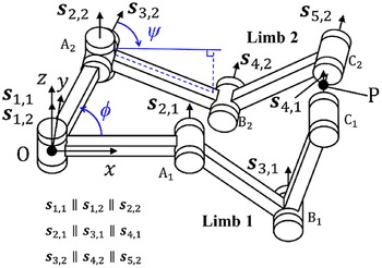

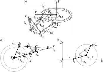

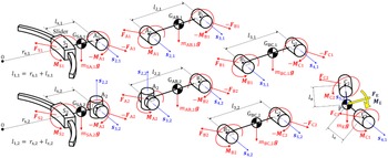

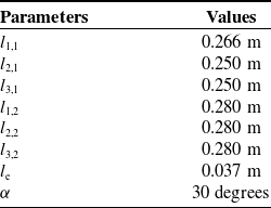

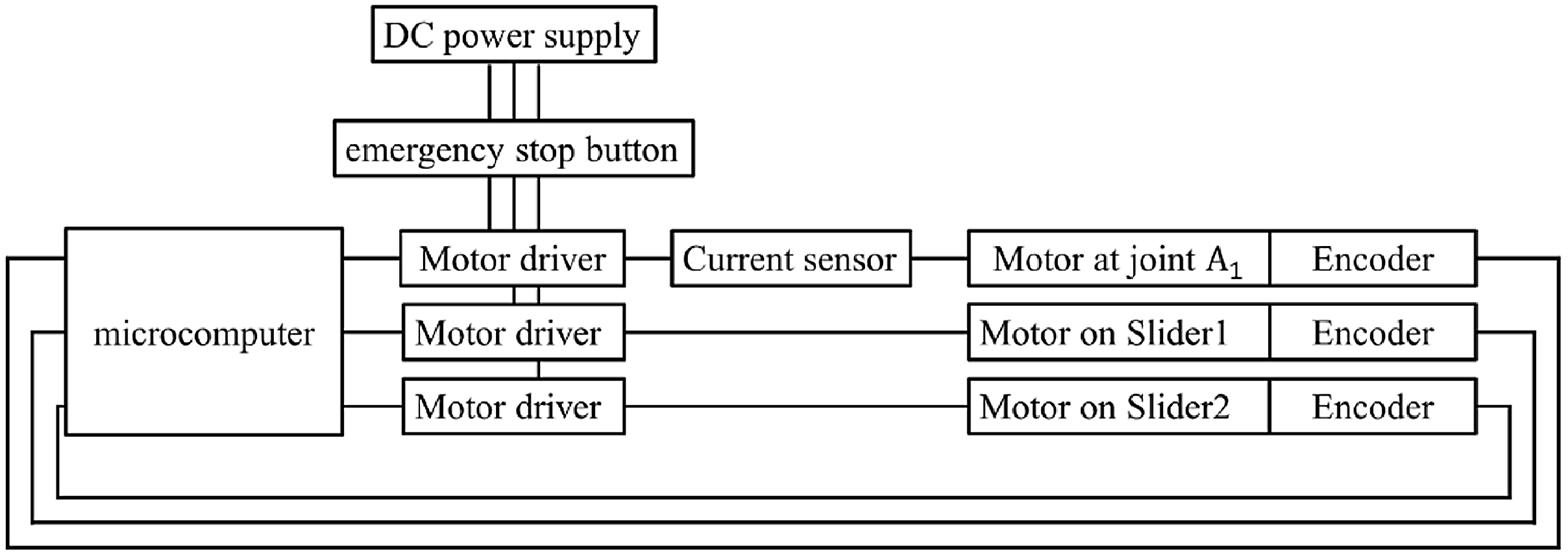

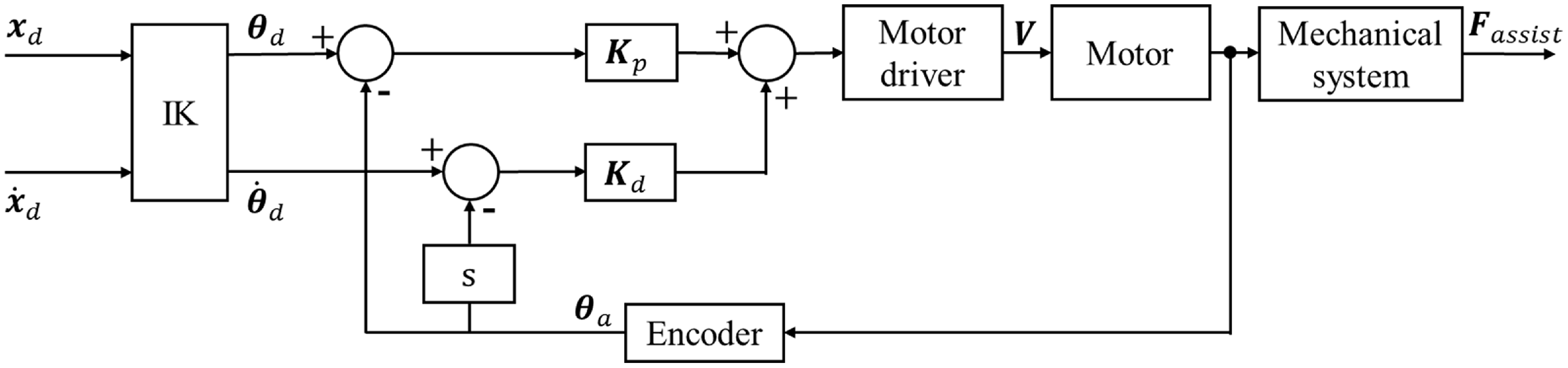
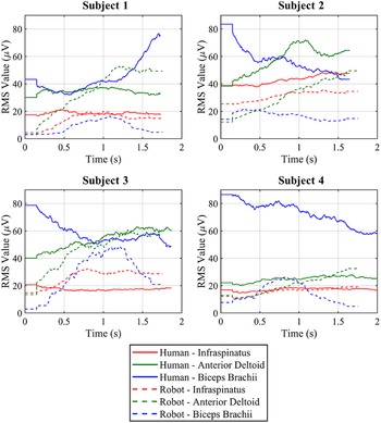

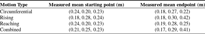


 Open access