


Introduction
Robotic science missions to the subsurface oceans of Europa and Enceladus, as well as deep investigations into the Martian ice cap, require a smart, high-power science payload delivery mechanism that is capable of penetrating large distances through ice. NASA’s Jet Propulsion Laboratory (JPL) conducted seminal work in the design of such a cryobot in the late 1990s (Reference Zimmerman, Bonitz and FeldmanZimmerman and others, 2001). The JPL cryobot measured 15cm in diameter and 100 cm in length and was designed to test the hypothesis that a radiothermal isotope source (Pu238) could be used to create a functional ice penetrator. That research ended in 2002, having successfully demonstrated that a 1 kW heat source would be sufficient to initiate and sustain motion of the a small-diameter vehicle through ice. The cessation of this work left many crucial questions unanswered, which we discuss below.
Delivery through deep ice caps
How can realistic planetary science sub-payloads be delivered through deep ice caps? In a Europa mission, the payload would be a relatively large nuclear-powered autonomous underwater vehicle (AUV) of the class needed for long-range exploration and biological searches in the Europan ocean (Reference Stone, Fairfield and KantorStone and others, 2007, Reference Stone2010; Reference GulatiGulati and others, 2010). Our estimates for the diameter of a flagship mission cryobot range from 1.5 to 2.0 m. The power required to melt ice for a given descent rate is proportional to the square of the vehicle diameter, so the delivery of large amounts of thermal power to the vehicle is necessary for a successful mission. In this sense, there have been no dramatic improvements in field-deployable cryobot architecture since the Philberth probe of the 1960s (Reference PhilberthPhilberth, 1962), since all designs have been electrically powered externally. Not only is this paradigm divergent from the nature of the power supply to be used on the flight vehicle, there is also an inherent limit to the range at which electrical power can be delivered effectively to an autonomous vehicle due to considerations of arc-over in the face of extremely high hydrostatic compression of insulator sleeves over adjacent wire wraps. Conversely, an Advanced Stirling Radioisotope Generator (ASRG) heat source is insufficient for conducting the cryobot-conveyed science missions described above. The next step-up is a compact fission-based Systems Nuclear Auxiliary Power (SNAP) or Topaz-class reactor operating in the mid-power range (20–100 kW).
Vehicle thermal management
How can we address the problem of dynamic thermal management of a vehicle that is powered predominantly by a thermal source, from which only limited local electrical power is required? The power source for any cryobot flight mission, whether radioisotopic or fission-generated, is thermal. It is wasteful to convert raw thermal power to electrical power, only to then use that power to transfer heat or cooling to some other location on the vehicle. The problem requires an actively controlled thermodynamic balance system that distributes heat where it is needed, or extracts it from where it is not, and only generates what is essential for the operation of inherently electronic devices.
Obstacle detection and avoidance
How do we implement active and effective long- and short-range obstacle detection in a cluttered and stratified ice cap? Moons like Europa have certainly been impacted by countless objects over the eons, and debris likely exists within the ice cap. This requires a means to generate full three-dimensional situational awareness of both large objects at long range (on the order of a kilometer away) and small centimeter-sized objects within intermediate ranges (tens to hundreds of meters) so that an optimal descent trajectory can be planned. It also means that the cryobot must be able to actively deviate from a vertical descent path.
Dealing with sediment build-up
Ice accumulates airborne dust on Mars and Earth, and similar material will be deposited during asteroid impacts with the outer planet icy moons. As the cryobot melts ice, sediment will be released and will accumulate ahead of the probe. This problem, known for some time in Antarctic research circles, has only been bypassed by brute force and megawatt-level hot-water drilling techniques (e.g. Reference Engelhardt, Kamb and BolseyEngelhardt and others, 2000). Limited success was obtained in a laboratory setting using hot-water jetting with the JPL cryobot (Reference Zimmerman, Bonitz and FeldmanZimmerman and others, 2001). The extension of these concepts to a functional vehicle capable of penetrating both downward and upwards in an ice cap many kilometers thick remains to be investigated.
Sample return
To date, sample return not been discussed in the literature since it has been assumed that any cryobot mission would involve a one-way descent and that data would be relayed back to a surface lander. A capability for sample return needs to be demonstrated.
Valkyrie: functional approach
Valkyrie was designed to address all of these issues and to field-test the solutions. We emulate the power of a small nuclear thermal reactor through an environmentally acceptable surrogate: a high-power surface-based continuous-wave (CW) laser. The laser beam is injected into an optical waveguide, or fiber, which is deployed from an on-board spooler in the aft-end of the vehicle as the cryobot descends. Upon emerging from the downstream terminus of the fiber, the beam is channeled and expanded into an anodized aluminum beam dump and heat-exchanger assembly at the nose of the cryobot. A portion of the optical power delivered to the beam dump is converted to electricity by arrays of photovoltaic cells lining portions of the dump. This electricity powers on-board electronics and hot-water pump jets. An end-fire synthetic aperture radar (SAR) images the area ahead of the vehicle for obstacles, and the vehicle is able to selectively use lateral hot-water jets to steer the vehicle in obstacle-avoidance maneuvers.
Valkyrie is a multiphase project. In this paper we focus only on two key technologies that have been developed in phase 2: (1) the delivery of laser power via fiber-optic waveguide and (2) the design of the vehicle’s beam dump. We present results of testing performed to validate those concepts. Details of the SAR system, sample return concepts, and the on-board astrobiology science payload and science objectives will be presented in later papers.
Laboratory Tests of Critical Technologies
High-power laser systems
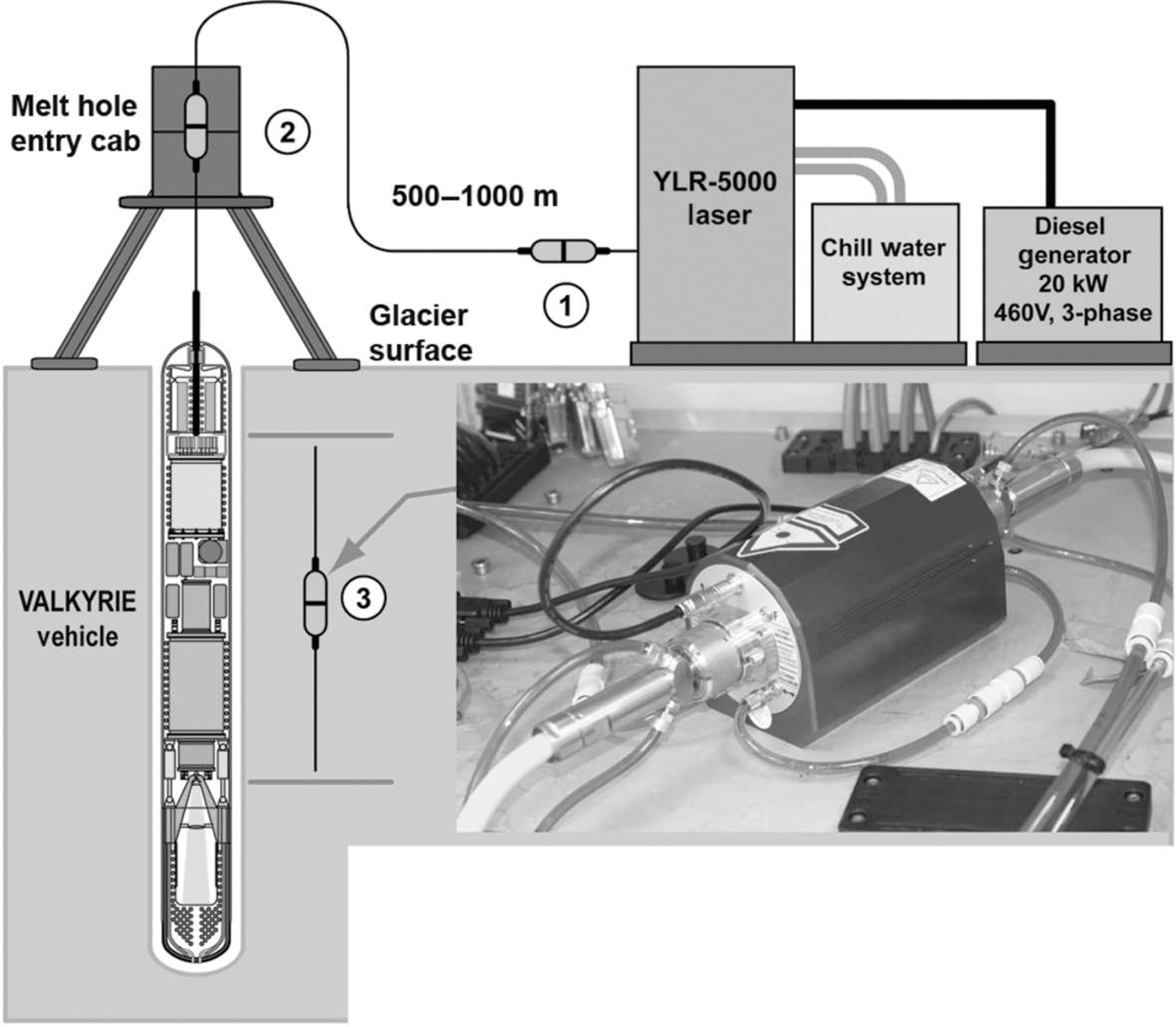
Valkyrie’s power source is a multimode CW 1070 nm diode-pumped ytterbium fiber laser (Fig. 1). In the phase 2 laboratory and initial fieldwork tests we are employing an IPG YLS-5000 laser with a nominal CW output of 5 kW; lasers of this class capable of producing up to 120 kW are available for developing higher-power cryobots in future phases. Figure 2 shows the anticipated set-up for the VALKYRIE phase 2 field campaign. Several high-power optical junction blocks (lower right image in Fig. 2) will be used to modularize the field set-up. Importantly, the power can be increased linearly. This will be significant for thermal management of VALKYRIE. A 5 kW laser is approximately equivalent to a refrigerator in size and mass. The electrical power conversion efficiency is 35%, which means that 15 kW of generator power is required to run the laser in a field setting; an additional 10 kW is required to run auxiliary systems including laser thermal control. While our risk reduction tests will operate at 5 kW, the units can be joined to produce a 50-100kW system, which will significantly improve descent speed for a realistic size subglacial mission to Antarctica in future project phases. Such power levels are approaching that of a small fission reactor, which might be considered for a Europa AUV mission.
VALKYRIE fiber laser.

VALKYRIE field test set-up.
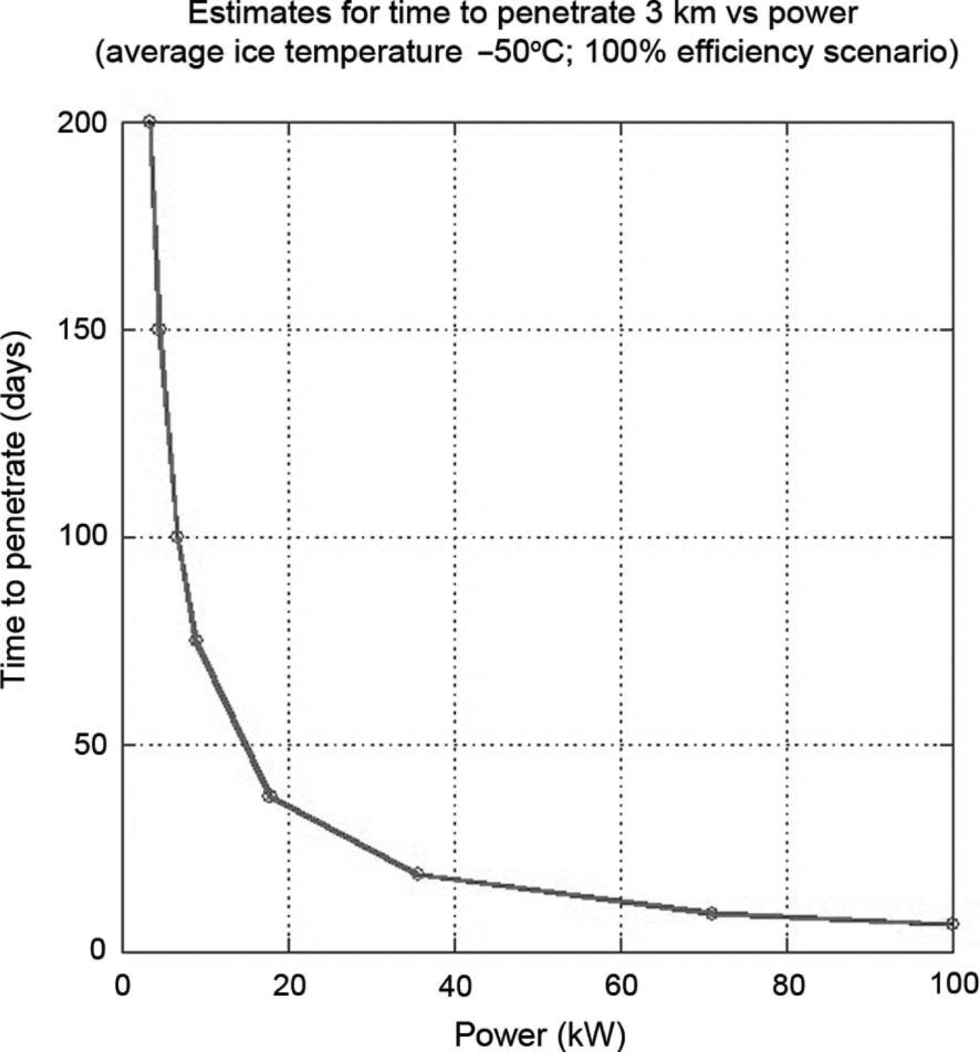
The above-mentioned laser statistics are for current (2013) fiber laser capabilities, but this technology has advanced at a rapid rate and it is likely that in the next few years we will see field-portable systems approaching 100 kW. The theoretical maximum power that can be conveyed by a single fiber is set by the catastrophic self-focusing limit Pcrit, which for fused silica fiber is ~4.3 MW (Reference Farrow, Kliner, Hadley and SmithFarrow and others, 2006). These limits far surpass current technology, but may one day be achievable. Importantly, this limit was calculated for a 25 um core fiber, which means that even a small cryobot will be able to receive high levels of power at long ranges, potentially in excess of 40 km. It is important to recognize that, within the power ranges we have investigated during this project, loss is dominated by fiber length, fiber cladding, configuration of materials and fiber bend radius among other factors, but not by the level of power transmitted. Figure 3 shows the consequences of this at the low end of this power scale for a 25 cm diameter cryobot. As we approach 100 kW, ice penetration times for a 3 km ice cap can be reduced to a number of days not months. An engineering optimization trade study will be required to balance logistics costs against the benefit of reduced penetration time for subglacial access in remote locations on Earth (e.g. Antarctica). It is our opinion that these power levels will be achievable in the next few years in compact systems and can be made available today by running off-shelf systems in parallel.
Mission duration as a function of input power for a 0.25 m diameter cryobot.
Optical power transmission
There are three fundamental technical questions confronting VALKYRIE: Is it possible to inject a high-power beam into an external optical waveguide? Will there be unacceptable power losses over a 3–4km penetration distance? Will the bending of the fiber to create an on-board spooler on the vehicle exacerbate power losses?
High-power fiber transmission tests were conducted by Stone Aerospace (SAS) engineers in July 2010. The optical waveguide was a custom-made silica fiber 1050 m in length with a core diameter of 400 µm, which was spooled onto a water-cooled polyethylene tray of 1 m diameter (Fig. 4). The spool diameter was chosen because it exceeds the theoretical threshold for significant power loss due to fiber-bending effects. The power transmission fiber, specified by SAS and manufactured by Polymicro, consisted of a multimode step index pure silica core with fluorine-doped cladding. It had the following layer structure: 400 µm core diameter, 440 µm outer diameter (OD) cladding and 480 µm OD polyimide coating (for the prevention of water intrusion). The composite fiber had a numerical aperture (NA) of 0.22.
Preparing 1050 m of fiber for the initial high-power transmission test.

For these high-power tests we used an IPG 20 kW multimode fiber laser (1070 nm, model No. YLS-20000).
The laser was calibrated, using a collimator and a Primes calorimeter, from 40 W to 20 kW prior to testing through the optical waveguide. Figure 5 shows the experiment architecture. Connection of modular high-power laser elements requires the use of special connectors in which the fiber is terminated into a fused quartz block within a water-cooled housing. Two connectors can be joined within a beam coupler (Fig. 6), which contains internal optics that expand, collimate and align the beam with the adjacent connector optics. The coupler housing is also water-cooled and contains several sensor interlocks that enable automated shutdown of the laser if the coupler overheats. These interlocks are required because the power levels are sufficient to initiate a fiber ‘fuse’ in the event of a thermal runaway in a connector or a defective spot in the fiber that causes it to overheat. In a fuse event, all of the laser energy is dumped into the failure point, which then fuses the silica fiber. The fuse then propagates rapidly back toward the laser.
Schematic of initial high-power transmission test.

High-power laser fiber switch.

We used a fusion fiber splicer to join the test fiber coil to the laboratory connectors (Fig. 7). We found that the use of a 300 µm core diameter connector fiber led to better coupling of power between the laser and the test coil. The power limit reached in the July 2010 tests was defined by the stray light that made its way into the multilayer cladding, where heat was absorbed and ultimately led to fuse formation. We addressed this issue by fabricating a makeshift cladding light stripper to remove the stray light from the cladding layer. This was accomplished by stripping off the polyimide coating from the fiber in the vicinity of the splice, then mounting to a heat sink and finally covering the splice with an index-matching gel, which had good thermal conductivity. The index-matching gel allows the light to escape the cladding layer, spill out and be absorbed into the gel and heat-sink assembly. This crude approach eventually led to a burn-through at the edge of the cladding light stripper at a power level of 11kW after several minutes. More effective proprietary splicing techniques were developed in the following 2 years, which effectively mitigated the fiber fuse problem.
Fiber splice for initial high-power tests.

Initial high-power test results
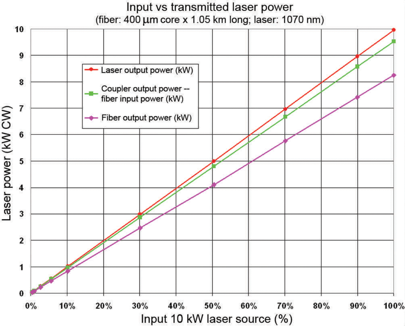
Using the set-up described in Figure 4, we cycled laser power from 0 to 10 kW through the SAS test fiber and measured the output power at the Primes calorimeter. The power loss in the fiber was measured at various laser output power points from 40W to 10 kW (Fig. 8). The fiber transmitted 86.6% (0.625dbkm–1) of the injected laser power at the 10 kW setting. The laser produced 9.955 kW at the 10 kW setting; this was reduced to an estimated 9.589 kW after splice, switch and coupler losses. The composite estimate for coupler loss was 1.5% (Fig. 8). The overall loss (at the SAS fiber output end) was very consistent over a range of injected power levels. The loss for the fiber was 13.4% km–1 (0.625db km–1). The theoretical limit for Rayleigh scattering of 1070 nm light in pure fused silica is 12.0%km– 1 (0.557db km–1) (Reference Ghatak and ThyagarajanGhatak and Thyagarajan, 1998). Temperature build-up in the SAS fiber coil (Fig. 9) never exceeded 30°C, validating our hypothesis that power loss through a fiber spool of large diameter was manageable. As previously mentioned there were significant issues with the fiber splice overheating both due to cladding losses and some unavoidable splice loss.
Transmission power results from first high-power test.
Thermal camera image showing temperature of the 1050 m fiber spool at steady-state full power (10 kW).

Bend loss tests
We are designing the VALKYRIE vehicle so that it can self-deploy the power tether via an actively cooled on-board fiber spooler. This approach is necessary because meltwater refreezing makes surface-based fiber deployment impossible. There is a lower limit to the spool’s diameter due to the increasing power transmission losses, or bend losses, as the fiber bend radius is reduced. Bend loss has both linear and nonlinear components. While significant research has been conducted by industry into bending loss for single-mode communications fiber, limited research has been conducted into bend loss for kilowatt-class multimode lasers. Available research (e.g. Reference Boechat, Su, Hall and JonesBoechat and others, 1991) and modeling predicts a large range of losses for various fiber types and applicable spooler sizes. Testing is underway at SAS to optimize fiber selection for bending loss, vehicle diameter and fiber strength with specific application to VALKYRIE.
Many parameters contribute to bending losses. Some key points from Reference Boechat, Su, Hall and JonesBoechat and others (1991) are as follows:
Bend loss depends on bend radius, increasing nonlinearly as the bend radius is decreased beyond a critical value.
Bend loss depends on fiber radius, increasing nonlinearly as the fiber radius increases, for a given bending radius.
Fiber losses decease nonlinearly as the fiber NA increases.
Bending losses are highly dependent on source conditions, particularly the source NA and source modal distribution.
Underfilling the fiber significantly reduces bend losses. Underfilling occurs when the launch condition of the source has a lower NA than the NA of the long-haul transmission fiber.
Higher-order propagating modes have higher losses, so the mode distribution of the source will affect the bending losses.
We are able to control all of these parameters to some extent, but the most difficult is the modal distribution of the source. Control of the modal distribution requires use of a mode scrambler, which we have yet to incorporate but are currently pursuing.
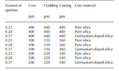
Our bend loss testing has examined fiber radius, bend radius and fiber NA as variables. An optical fiber is typically constructed with a fiber core, fiber cladding, fiber coating and, often, a fiber jacket. Owing to volume constraints for our application, we have chosen to use unjacketed fibers. Table 1 lists the nine Ceramoptec fibers we have tested. Each fiber is multimode step index and has a polyimide coating. The 0.22 NA fibers have standard fluorine-doped silica cladding, the 0.28 NA fibers have a proprietary fluorine-doped silica cladding and the 0.37 NA fibers have a germanium-doped core.
Specifications for fiber types used in bend loss tests
Our conclusion from these tests is that on-board fiber spoolers will need to have a minimum radius of 100 µm and a fiber NA >0.28 in order to keep bend losses low. The same performance levels can be achieved with lower-NA fibers, but with commensurately larger spooler diameters (~150 µm radius). The VALKYRIE spooler is presently being designed with a 100 µm radius.
Fiber spooler design and testing
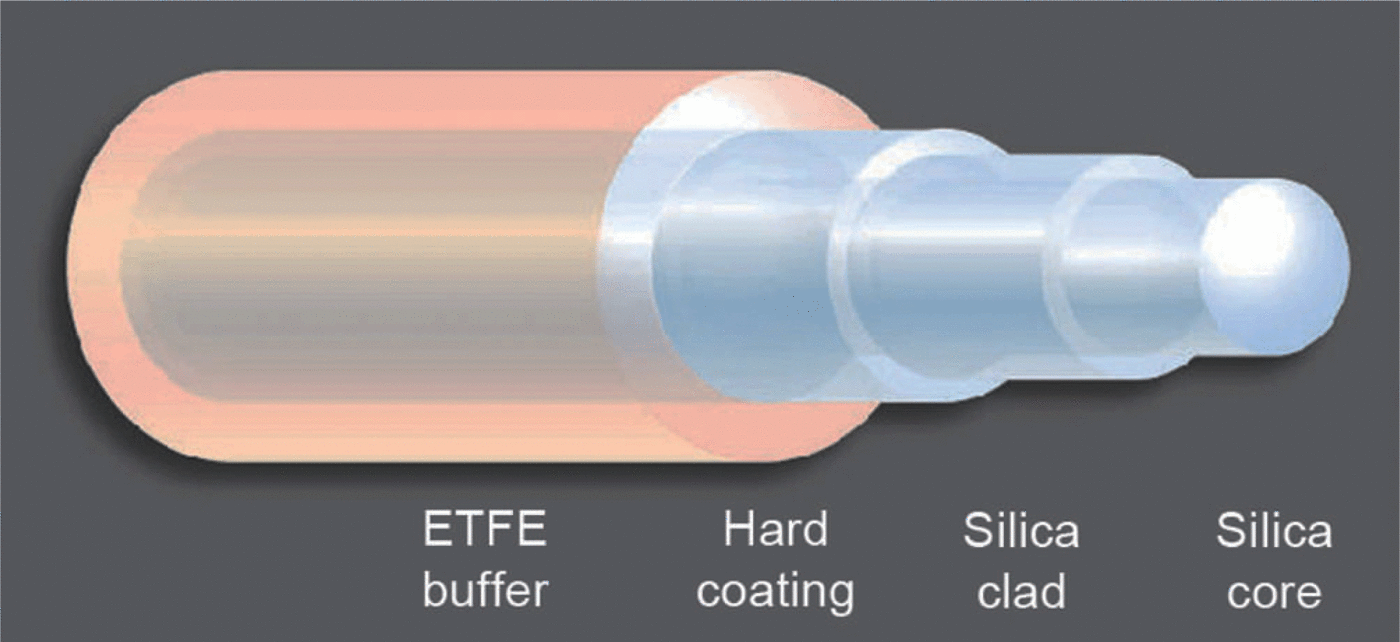
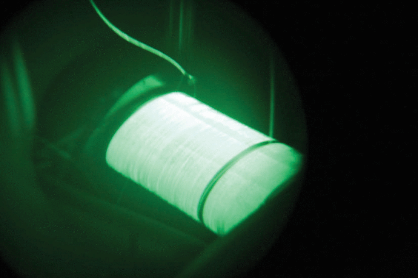
We tested a full-scale spooler mock-up (Fig. 10) to determine realistic fiber transmission loss rates and compared these with predicted results. We also observed the thermal conditions and overall performance of the spooler mock-up. We wound 250 m of fiber on the spooler, a length sufficient to enable all field campaign work envisioned in phase 2. The fiber was fabricated by OFS and had a 365 µm pure silica core, with a 400 µm doped silica cladding (NA = 0.22) and HCS/ETFE outer coatings (see Fig. 11). The spooler had a diameter of 0.22 m and a length of 0.5 m, with an aluminum mandrel and Delrin flanges. A layer of Bergquist thermal foam was used to line the spooler surface to enhance heat transfer and reduce fiber micro-bending. For this test series the bare fiber was wound onto the spooler drum by hand (Fig. 12) to ensure that successive wraps did not overlie prior wraps. Micro-bending due to such fiber overlap has been reported to lead to premature failure of telcom fibers, and in a high-power transmission scenario fiber overcrossing is to be explicitly avoided. During our previous high-power testing, the fiber splice joints ran quite hot, with one test terminating prematurely because of a fiber-fusing event. We improved the splice technique in subsequent tests and observed only a moderate temperature rise of ~348°C at steady state.
Set-up diagram for high-power tests of the VALKYRIE fiber spooler.

Schematic of the optical waveguide layers used for the spooler tests.
Winding the VALKYRIE high-power fiber spooler.

In our tests the beam entered the spooler fiber (Fig. 13) with an NA of ~0.10 (11.580 full angle of divergence), and exited the fiber with an NA of ~0.16 (18.40 full angle). This divergence is principally a result of mode conversion to higher-order modes due to the bending of the fiber around the spooler. The beam coming from the fiber laser has a low divergence angle. When the beam initially enters the fiber spooler, the fiber is said to be ‘underfilled’; the ability of the fiber to guide the beam (fiber NA) is greater than the beam divergence (beam NA), so no power is lost in bending. As the light travels further down the spooled fiber, the continued bending and resulting mode conversion causes increasing beam divergence until it reaches some critical fiber length where the beam divergence exceeds the fiber’s ability to guide it; this is where power losses due to bending begin. A fully developed beam exists within the fiber when the system reaches an equilibrium where all additional beam divergence from continued bending is lost, resulting in a steady-state loss operating condition. A critical length of ~500 m is required for the beam to fully develop within the fiber. For our chosen spool diameter of 0.22 m, these losses should still be well controlled even at 500 m.
Infrared image of the VALKYRIE fiber spooler at 5kW power input.
We used a collimator of 50 µm diameter and 100 µm focal length with internal water cooling. We were able to measure both the power and beam profile output from the fiber. Power was measured with a PRIMES power monitor, and showed much lower bend loss than expected. The initial spooler tests were performed with the spool submerged in water, but the spooler and water bath temperatures never rose significantly above room temperature. We then conducted the same tests with the spooler in air. The steady-state result is shown in Figure 14, a thermal image that indicates a maximum temperature of 36°C in the fiber. This is an encouraging result, which provides a margin of safety during initial vehicle power-up for field campaigns.
Thermal camera image showing steady-state temperature distribution on the fiber spooler mock-up at 5 kW input power.

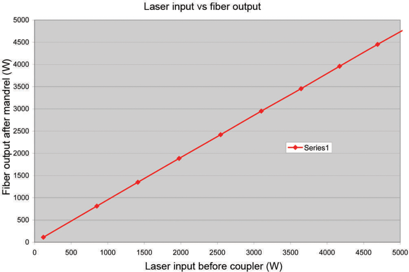
Figure 15 shows received post-spooler power versus input power from the laser. It is estimated that ~ 1 % of the initial input power is lost in the fiber coupler, a loss of -3.6% of input power comes from the basic fiber loss for 250 m, ~ 0 . 1% of input power loss for the collimator and ~ 0 . 1% loss for the splice, which results in an estimated average value of -0.4% bend loss.
Power output from the spooler as a function of input power.
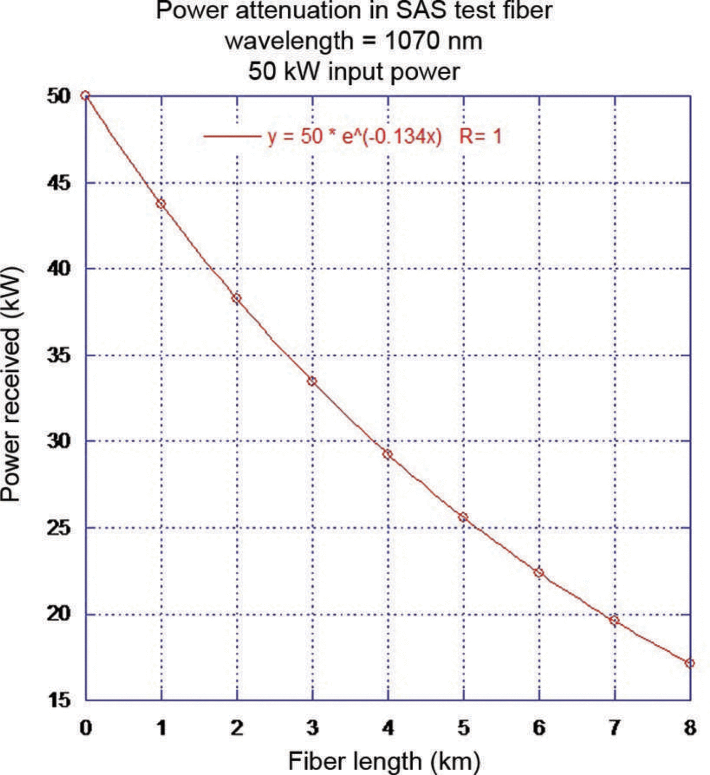
While we will only be using up to 5 kW of laser power in the phase 2 vehicle, we extrapolated the predicted field performance of the laser power system we might use in future for higher-power and longer-range versions of VALKYRIE. This extrapolation, based on the high-power 1.05 km fiber test, fiber bend loss tests and high-power spooler tests, is shown in Figure 16 as power delivered to the vehicle versus vehicle range. The value of 8 km of fiber was chosen because it is sufficient to reach, and return from, the deepest known subglacial lakes on Earth. At such a range we predict that a 50 kW surface supply system could deliver ~18kW of optical power to the vehicle at maximum spool-out. During the early stages of descent there would be nearly as much power dissipated in the spooler from bend losses as there would be at the melt head. Fluid management systems could use this spooler heat to amplify the heat extracted from the beam dump heat exchanger, leading to faster descent rates.
Theoretical power delivered to VALKYRIE as a function of spooler length for 50kW input power.
Vehicle Design
Mechanical design
Figure 17 shows a block diagram for the phase 2 prototype vehicle. The vehicle is currently 25 cm in diameter and 2.8 m in length. This cross section makes an Antarctic subglacial lake mission a feasible option for future phases using existing laser technology. The primary power fiber spooler, shown in Figure 17 at the right-hand end of the vehicle, is 0.5 m in length, has an OD of 0.22m and can accommodate 8km of fiber. Communications fiber will be spooled separately. We currently expect to run a QBH fiber pigtail from the fiber spooler, with an optical splice adjacent to the spooler. This in turn plugs into the external pressure hull of the beam dump, where it will guide the beam to the diverging optics assembly. The optics assembly is designed to achieve a uniform beam intensity over the high-temperature photovoltaic (PV) arrays located on the beam dump endplate and side walls.
VALKYRIE functional diagram.
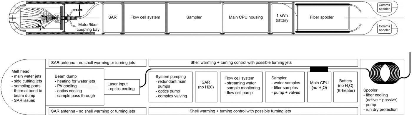
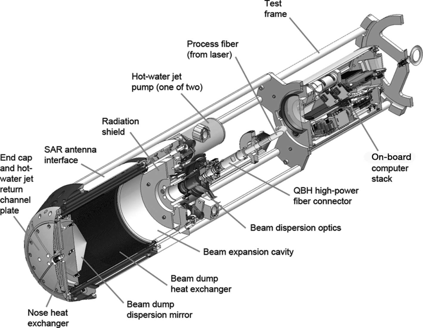
In 2013, efforts were focused on design completion and the fabrication, integration and testing of a basic cryobot vehicle that could demonstrate critical melt head functions: laser power-to-heat conversion, electrical power generation via laser light on PV cells, and hot-water pumps and jets. Figure 18 shows a section view of the prototype with the following functional sub-systems:
beam dump and pressure housing (at far left of figure)
heat exchangers
hot-water jets, filters and pumps
beam-dispersion optics
on-board control computer stack
high-power laser fiber field junction
laser power, communications and liquid-cooling umbilical.
Solid model section of the initial test prototype for VALKYRIE.
An early decision in the design process involved the separation of the testing of two critical beam dump elements: the heat exchanger and associated beam-dispersion optics and hot-water jet systems, and the power generation system, consisting of a tuned-wavelength heat-tolerant PV array that would see incident laser flux on the order of 10 Wcm–2.
The beam dump heat exchanger (Fig. 19) must perform several complex tasks within a compact volume. First, it must efficiently collect heat from the laser beam and transfer it to the water routed through the ice-melting jets at the nose of the vehicle. The interior side walls contain scores of forward-facing beveled circular grooves that serve to absorb radiant energy and prevent back-reflection towards the beam-dispersion optics. A non-off-gassing ‘optical black’ ceramic coating was anodized onto the metal to further enhance heat absorption and minimize reflection. Heat transfer is maximized through the use of a microchannel heat exchanger consisting of hundreds of small vertical channels that transfer the returning meltwater through the hot side walls. Diaphragm pumps, discussed below, then pump the heated water through larger channels to reach the nose-mounted melting and turning jet nozzles. Switchable piping enables the vehicle to channel hot water selectively to turning jets or to direct descent jets. The beam dump must also accommodate electrical sensing lines between the vehicle’s nose and on-board computer, and serve as the physical interface to the SAR antennas.
Rear view of the VALKYRIE beam dump heat exchanger.

The forward end of the beam dump radiates heat into the side walls through the use of an infrared reflector (Figure 20). The back side of the reflector cap (Fig. 21) contains a series of planar heat-exchanger channels that serve to cool the reflector and, in later designs, will cool the PV array. A final nose-cone cap plate (Fig. 22) contains the forward melt jet and cruciform-shaped meltwater return channels that draw water back through the heat exchanger. In the black-colored housing of the heat exchanger, behind the bare aluminum front caps in Figure 22, two of the later turning water jets can be seen mounted in the black anodized cone.
Mating the mirror assembly to the front of the VALKYRIE beam dump.

Cooling channels on the back side of the beam dump for mirror cooling.

Assembled VALKYRIE prototype beam dump and melt head.

The rear of the beam dump (Figure 23 is populated with fluid-control systems, including redundant diaphragm pumps for driving the hot-water jets, pre-pump intake filters and overpressure regulators. The final design will include servo-controlled pump output routing valves to steer flow to lateral cutting jets, as required. Shell heaters, required to prevent premature refreeze, are controlled by diverting hot water from the beam dump heat exchanger. Heat for this purpose is also extracted from the fiber spooler heat exchanger (not shown). Figure 24 shows the assembled test vehicle. For simplicity the on-board fiber spooler that will be used in the year 4 field campaign was left out, and an armored fiber connects the melt head optics to the beam dump.
Hot-water jet pumps, filters and valve assemblies on the back of the beam dump.

The assembled laboratory test vehicle.

Melt head thermal design
There are three primary thermal states that can arise on a mission during the operation of the VALKYRIE cryobot: case A – full laser power (5kW) and the hot-water jets operating; case B – full laser power and failure of both water pumps; and case C – full laser power with the jets disabled and water being recirculated through the beam dump heat exchanger with the pumps functioning. Case C will be implemented while taking water samples from the front of the vehicle.
We examined each of these states (Figs 25–27) in detail using finite-element analysis thermal modeling procedures (SolidWorks 2012 Flow Professional). Initial design concepts centered on the idea of using beryllium oxide as the beam dump material, but toxicity issues and the complexity of the necessary piping precluded this option on the grounds of fabrication problems. We investigated copper as a material, but it is not available in large billet sizes and similarly cannot be cast with the very complex internal channels required. Ultimately we used a machined block of T6061 T6 aircraft alloy aluminum and a heat-resistant, photon-absorbing, non-off-gassing anodized coating. With that basis we began investigating the concept of using wire electrical discharge machining (EDM)-milled microchannels as the basis for the heat exchanger. This option yielded the highest heat flow rate, and EDM machining could bore hundreds of straight small-diameter holes through the 30 cm length of the beam dump side walls.
Steady-state beam dump temperatures at 5 kW with water jets operating.
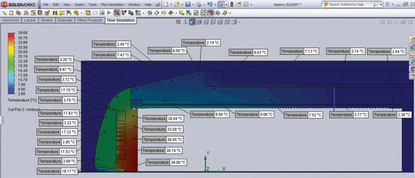
Steady-state beam dump temperatures at 5 kW and failed water jet pumps.
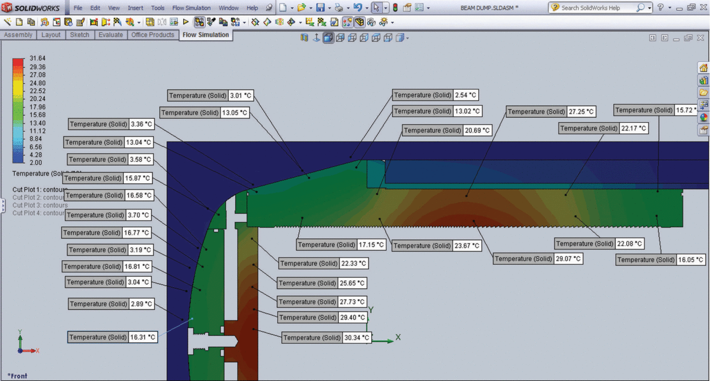
Steady-state beam dump temperatures at 5 kW with internal recycling of water.
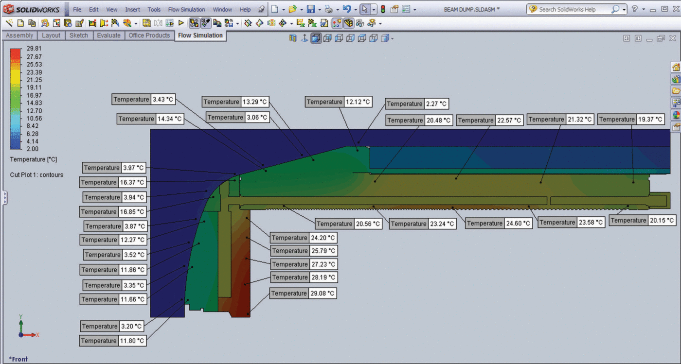
Analyses then focused on the spacing, number and diameter of the microchannels. The final microchannel count was 328 x 1.6 µm diameter vertically machined holes (Fig. 19). Owing to computation power constraints, simulations were simplified. All simulations were performed using a 0.000322 Km2W–1 resistive contact between all mating surfaces. A heat flux of 85 kWm–2 was applied to the end face of the beam dump, and a heat flux of 35 kWm–2 was applied to the cylindrical side walls of the dump. The nose was in contact with a simulated body of ice using the same boundary resistance as the rest of the model, while the rear (cylindrical) portion was isolated for the flow modeling. Flowing water was simulated differently for different sections of the vehicle. At the heat exchanger, a small radial section was used in a detailed analysis to determine how much heat was transferred to the flow per unit radial area. Using these results, we then modeled the entire dump and put a flow condition on the outlet of the heat exchanger, which had the water temperature results from the previous detailed heat exchanger section modeling. This simulation of the entire dump also included flow through the nose channels, so that heat picked up was then calculated. All simulations were based on a 5 L min–1 flow rate. The inlet water temperature was set to 2ºC for the heat exchanger modeling. The test data show that the computational fluid dynamics simulations are within a few degrees Celsius of the measured flow temperatures. The steady-state temperature rise of the water was 10ºC and the PV power conversion cells can operate at >100ºC.
For case A simulations, the peak steady-state end-face temperature rose to 39ºC and the side-wall temperature rose to 10ºC. For case B (pump failure at full laser power), peak side-wall temperature reached 29ºC; in case C (recirculation mode), peak side-wall temperature is <25ºC. From these simulations we conclude that, in all conditions, heat transfer through the side walls of the beam dump is satisfactorily efficient. Further, simulation results show that temperatures within the dump do not approach the service limits of internal materials or electrical components. Of these, the PV cells are the most sensitive; they are rated for service at temperatures up to 125ºC, but performance declines with increasing temperature. We have therefore set a maximum acceptable temperature of 70ºC for the inside of the beam dump to provide a margin of safety and ensure good PV cell efficiency.
Sample return and future project phases
Ultimately, VALKYRIE is intended as a viable alternative to deep drilling for a clean deep sample return mission. Owing to limitations of funding we have broken the project into several phases, beginning with the issue posing the largest technical risk: is it possible to pump large quantities of photons down an optical waveguide and then use them to do something useful at the other end? In this paper, we have presented the results of our work in this area thus far, with the full intention of addressing the more refined challenge of sample return in subsequent research and development. VALKYRIE is being designed as an extension of AUV technology developed at Stone Aerospace. As such, buoyancy control and attitude control are common engineering requirements we deal with. The present end-to-end VALKYRIE mission scenario we are ultimately working towards (Fig. 28) is as follows:
an autonomous descent vehicle will breach the roof of a subglacial lake;
a conversion process will then begin in which the vehicle performs a 908 pitch-up maneuver to function as an AUV for as much as 1 km of horizontal investigation from the melt hole;
the vehicle will collect both water and sediment samples in the subglacial lake;
an inversion system will then be activated that causes the vehicle to perform another 908 pitch-up maneuver;
a buoyancy engine will activate and cause the vehicle to rise up through the ice cap.
Envisioned subglacial lake sample return mission: (1) descent through the ice cap; (2) vehicle pitch-up maneuver and conversion to AUV; (3) bottom sample acquisition and bathymetric mapping; (4) vehicle pitch-up maneuver with center of gravity shifting and buoyancy increase; and (5) return to surface.
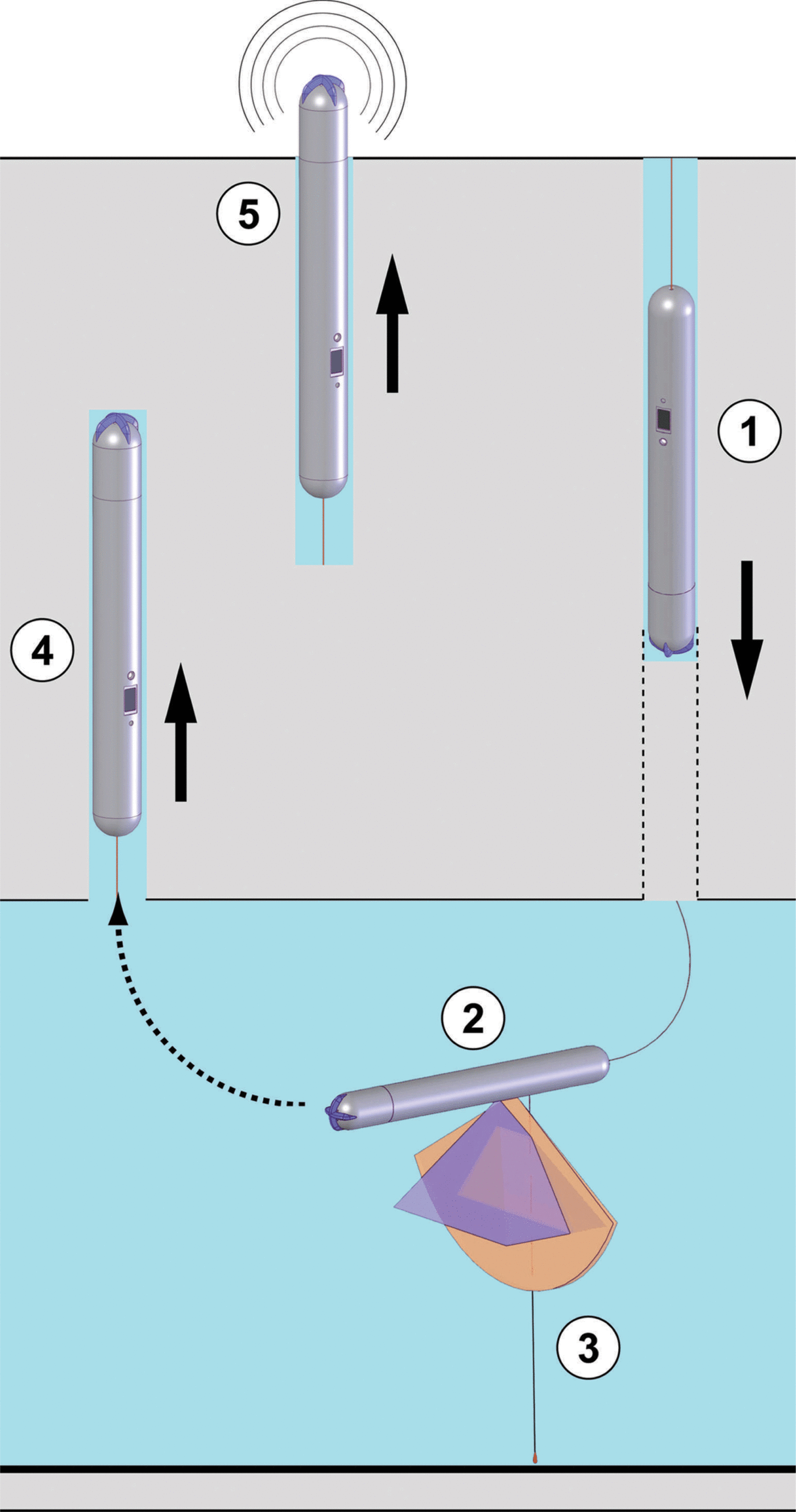
The final two maneuvers will be accomplished through the use of center-of-gravity shifters and either an actively operated buoyancy engine or a drop-mass release. In either event, the vehicle will rise up through the ice at approximately the same rate of descent, effectively rising buoyantly in an ice-bound body of water. In glaciers without a firn layer, the vehicle should be able to reach the surface directly; in ice masses covered by firn a small hot-water drill will be needed for recovery in the final 80–100m. The SAR in the vehicle nose will serve as a localizer beacon for recovery of the vehicle. Since there is no requirement for the vehicle to surface at the point of entry into the glacier, ice stratigraphy data can be acquired for two completely separate penetration lines through the glacier.
Field-testing of the phase 2 vehicle design will take place on Matanuska Glacier, Alaska, USA, in 2014 and 2015. This is a polythermal glacier and, to the depth extent of the test missions planned for phase 2, the melt hole will not refreeze during the tests, allowing vehicle retrieval via stainless-steel cable.
Conclusions
We have developed a working prototype for a cryobot that receives its power from a high-energy laser beam channeled into an optical waveguide that is stored on, and released by, the cryobot as it descends through an ice cap. The laser beam is expanded into a beam dump where the majority of the heat content is extracted through an efficient microchannel heat exchanger, which is provisioned by meltwater generated in front of the beam dump. Additional thermal power is extracted from a subsidiary heat exchanger controlling the temperature of the on-board fiber spooler. Both heat sources are used to heat incoming water, which is routed through hot-water jets on the vehicle’s nose. The jets can be selectively powered to produce forward and diverting trajectories. Lateral jets can also be used to turbulently remove released sediment. A portion of the beam impinges on a multistage high-temperature PV array, which generates electrical power to run all vehicle pumps and electronics directly. A reserve battery is used to start up the on-board control system prior to laser power-up.
We expect to conduct field tests of the basic vehicle, with science payload elements (a deep-ultraviolet flow cytometer for fluorescence-based microbe detection and water and filter sample collection systems, to be discussed in subsequent papers), on Matanuska Glacier beginning May 2014. The field tests will be conducted using a 5 kW 1070 nm fiber laser powered by a 30 kW diesel generator.
The theoretical basis for this significant departure from traditional ice-penetrating technology has been validated through laboratory testing by our team at power levels up to 11 kW. The limitations of that test (failure at a fiber junction) have been addressed, and it is our opinion that transmission of power levels an order of magnitude higher should be achievable within this decade. At such levels, an autonomous entry into a subglacial lake (e.g. Vostok Subglacial Lake, East Antarctica) could be achieved with a penetration time of 1 week.
Importantly, VALKYRIE is a self-contained autonomous system. Although high-bandwidth communications can be maintained with the vehicle, either by modulating a separate signal on the laser fiber or by trailing a separate smaller telcom fiber, it is important to recognize that this glass thread will be frozen in the descent path as it is spooled out from the vehicle. Forward contamination of a subglacial lake can thus be prevented by controlled decontamination of the vehicle to accepted planetary protection levels in a laboratory environment prior to the mission, and transport to the test site in a sterile transport mechanism. A sterile insertion mechanism will start the vehicle on its downward journey into the ice cap; the vehicle will subsequently travel in its own void, which will refreeze behind the descent path. This methodology will reduce surface supply logistics requirements to that of the laser and its thermal regulation equipment, a diesel generator, fuel and crew support.
Acknowledgements
Valkyrie is a NASA-sponsored research activity, funded through the ASTEP (Astrobiology Science and Technology for Exploring Planets) program office, NASA Science Directorate, under grant NNX11AJ89G. The team would like to thank Mary Voytek at NASA Headquarters for her vision, support and guidance throughout the project.



