


1. Introduction
The 3D printing technology allows faster and cheaper production of simple and complex shape components for small- and mass-volume manufacturing, in loco or decentralized, from a sustainability perspective [Reference Attaran1]. Research and education, manufacturing of prototypes, architecture and civil engineering [Reference Labonnote, Rønnquist, Manum and Rüther2, Reference Prashar, Vasudev and Bhuddhi3], automotive and aerospace [Reference Murr4, Reference Rinaldi, Cecchini, Pigliaru, Ghidini, Lumaca and Nanni5], medicine [Reference Palo, Holländer, Suominen, Yliruusi and Sandler6], and food [Reference Sun, Zhou, Huang, Fuh and Hong7, Reference Lille, Nurmela, Nordlund, Metsä-Kortelainen and Sozer8] are some of the fields of application for 3D printing. The most adopted process of this technology is the material extrusion (MEX) process [Reference Agarwala, Jamalabad, Langrana, Safari, Whalen and Danforth9, Reference Turner, Strong and Gold10]. One or more heated nozzles fuse a solid filament of material. The resulting semi-solid form is extruded, and, layer by layer, it is laid down to construct the geometry of the component to build. Many research activities have been conducted in recent years to increase the performance of the MEX process: to save material and speed up the printing procedure, the used substrates have been optimized [Reference Feng, Li, Zhu, Thakur and Wei11]; to improve the mechanical performance of the fabricated components, optimal values of the printing parameters have been achieved [Reference Khosravani, Berto, Ayatollahi and Reinicke12–Reference Karad, Sonawwanay, Naik and Thakur14]; to realize innovative mechanical systems, new solutions have been proposed [Reference Li, Tsavdaridis and Gardner15].
The effect of the staircase, the removal of the support material, shape distortion, dimension and shape deviations between the current piece and the nominal one, porosity of the external surfaces, and discontinuous or more contour lines can occur [Reference Wickramasinghe, Do and Tran16]. Such issues could compromise the functionality, the mechanical assembly, and the aesthetic appearance of MEX 3D-printed components. For improving the surface finish, dimensional requirements, and aesthetic quality [Reference Lalegani Dezaki, Mohd Ariffin and Ismail17], CNC milling or contouring machining was traditionally carried out and has inspired several research activities: a test campaign was planned by a Design of Experiments to identify the best combination of cutting parameters to minimize the surface roughness of polylactic acid (PLA) components [Reference El Mehtedi, Buonadonna, Carta, El Mohtadi, Marongiu, Loi and Aymerich18]; a similar analysis was extended to components made of polyethylene terephthalate (PETG) and carbon-fiber-reinforced PETG [Reference El Mehtedi, Buonadonna, El Mohtadi, Loi, Aymerich and Carta19].
More recently, robotic solutions have been demonstrated to be a valid alternative to CNC machines [Reference Ji and Wang20–Reference Maghami and Khoshdarregi22]. The versatility to perform complex paths and different tasks, larger workspaces, and lower costs [Reference Iglesias, Sebastiàn and Enrique23] make robots preferable to CNC machines. Nevertheless, the stiffness of a robot, which is lower than 1 N/ $\mu$
m compared to more than 50 N/
$\mu$
m compared to more than 50 N/ $\mu$
m of CNC machines, could cause position errors and vibrations responsible for low accuracy and poor quality in the manufactured products [Reference Perez-Ubeda, Gutiérrez, Stanisic and Lluch-Cerezo24]. Industrial robots are predominant in this field [Reference Iglesias, Sebastiàn and Enrique23, Reference Makulavičius, Petkevičius, Rožėnė, Dzedzickis and Bučinskas25], while, due to their lower stiffness, collaborative robots (cobots) [Reference Yuzhang. and Qingsong26–Reference Scalera, Lozer, Giusti and Gasparetto29] have limited applications. For contouring machining, a study has demonstrated that an external control loop is necessary to adjust the stiffness and follow the desired trajectory [Reference Makulavičius, Petkevičius, Rožėnė, Dzedzickis and Bučinskas25]. An application expected the use of a cobot to apply a constant force on a vertically guided drill, thereby minimizing tool vibration and burr formation [Reference Miyake and Kondo30].
$\mu$
m of CNC machines, could cause position errors and vibrations responsible for low accuracy and poor quality in the manufactured products [Reference Perez-Ubeda, Gutiérrez, Stanisic and Lluch-Cerezo24]. Industrial robots are predominant in this field [Reference Iglesias, Sebastiàn and Enrique23, Reference Makulavičius, Petkevičius, Rožėnė, Dzedzickis and Bučinskas25], while, due to their lower stiffness, collaborative robots (cobots) [Reference Yuzhang. and Qingsong26–Reference Scalera, Lozer, Giusti and Gasparetto29] have limited applications. For contouring machining, a study has demonstrated that an external control loop is necessary to adjust the stiffness and follow the desired trajectory [Reference Makulavičius, Petkevičius, Rožėnė, Dzedzickis and Bučinskas25]. An application expected the use of a cobot to apply a constant force on a vertically guided drill, thereby minimizing tool vibration and burr formation [Reference Miyake and Kondo30].
This work describes the development of a previous activity [Reference Antonelli, Brunetti, D’Ambrogio, Mattei and Stampone31] focused on adopting a cobot for contouring machining to be installed within a new generation of large print volume (2000 x 1000 x 1000 mm) industrial MEX 3D printers. A sensorized end-effector for an Omron TM5-700 cobot was designed, prototyped, and adopted. It consists of a powered contouring tool and three load cells for measuring the cutting forces on workpieces made of PLA. This material was chosen because of the availability of experimental data in the literature [Reference El Mehtedi, Buonadonna, Carta, El Mohtadi, Marongiu, Loi and Aymerich18]. The tool path planning is based on a 3D CAD model and adapted to the current position and orientation of the workpiece using a vision algorithm and a touch-stop operation. The 3D CAD model plans the tool path with respect to the nominal dimensions and orientation of the workpiece; the vision algorithm, combined with the touch-stop operation, compensates the planned tool path from the previous nominal entities to the current ones. A test campaign was carried out to evaluate the roughness and developed cutting forces as a function of different cutting parameters involved in the contouring machining. Results confirm the feasibility of the cobot-based contouring machining.
This study introduces several novel contributions to the field of robotic machining, particularly in the context of cobots applied for post-processing of thermoplastic 3D MEX parts:
-
• The feasibility, effectiveness, and robustness of using a cobot for contouring tasks were validated by the proposed workflow and the acquired and analyzed quantitative data of cutting forces and surface roughness throughout the machining process.
-
• The development of a cobot-based station equipped with a custom-designed and low-cost end-effector, specifically conceived to work within a new generation of large-volume 3D printers that can also perform post-processing machining operations.
-
• A complete procedure for programming the cobot without an in-depth knowledge of the cobot programming software. This item extends the proposed methodology to each 3D CAD software and cobot. Moreover, the procedure allows for detecting the workpiece alignment, adjusting the tool path according to the current position and orientation of the workpiece, force monitoring, and parameter optimization.
To our knowledge, this is among the first comprehensive implementations to achieve surface finish quality comparable to traditional CNC machining while maintaining system flexibility and ease of use. The approach offers an accessible solution for enhancing the surface quality of 3D-printed parts, with relevance for flexible, low-cost, and small-batch production scenarios.
The work is structured as reported below. In Section 2, the proposed tool path planning procedure is described. In Section 3, the robotic station is presented, focusing on the description of the developed end-effector and calibrations of the ground plate and tool center point (TCP). The experimental activity is reported and discussed in Section 4. Section 5 concludes the work with considerations and potential future improvements.
2. The proposed procedure for the tool path planning
A generalized methodology for tool-path planning has been conceived and is detailed below. The 3D solid geometries of the components to print are first generated by 3D CAD modeling software; hence, they are exported in a proper file format into the 3D printer software that requires their placement on the printing plate and generates the G-code for the motion of the extruders. Printing parameters must be set before printing is launched. The result of this process is the creation of objects whose dimensions and positions within the workspace of the printers are affected by the printer’s working tolerances (±0.05 mm for professional 3D printers). In addition, sometimes, defects appear on the external surfaces.
For the contouring machining of the latter, in a new generation of large 3D printers, adopting a robotic solution does not require removing components from the printing plate. Specifically, the nominal geometries and placements are well-known thanks to the software application adopted for their drawing and printing. Nevertheless, it is necessary to associate the workpiece placement with the robot reference systems and, consequently, plan the tool path. The latter must be defined considering the complexities of the geometries, the available space among the printed objects, the necessity to avoid impacts between them and the robot, and the possibility of optimizing the path and reducing the time for the tool path planning and execution. Another significant aspect is that complex geometries must be generally imported into the robot’s programming software using coding or procedures, depending on the adopted software.
The proposed procedure expects:
-
• The adoption of any 3D CAD software for drawing the components and organizing them on the printing plate with respect to the drawn 3D model of the cobot and its reference system in the same environment.
-
• By the same 3D CAD, the easy drawing of the tool path since geometries and placements of the components are well-known (Fig. 1(a)). Moreover, tool dimensions can be easily represented and modeled for the contouring machining.
-
• The exportation of the generated 3D CAD file with component geometries, tool paths, and robot into a simulation environment (Fig. 1(b)).
-
• In the simulation environment, the definition of the kinematic and dynamic constraints of the robot to perform the tool path, the calibration of working planes, the creation of event sequences, and time delays.
-
• The offline simulation of the planned tool path for validating or improving the contouring machining. During this step, further requirements for the purpose and an iterative refinement with the 3D CAD software could occur.
-
• The automatic conversion of the validated tool path from the simulation environment to the robot programming software. This step avoids the specific in-depth knowledge of the programming software of the adopted cobot.
-
• The run of the robotic task and final validation (Fig. 1(c)).
Steps of the proposed tool path planning procedure: (a) detail of the drawn component and the tool path by 3D CAD software; (b) the workpiece and robot geometries and the planned tool path in the simulation environment; (c) example of the comparison between a drawn tool path and the executed one (in this case the tool was a pen moved on a sheet of paper).

The present study used Siemens Solid Edge™ as 3D CAD software. RoboDK® was adopted as the simulation environment, whose post-processor can automatically write a script file with the task instructions converted according to the language of the cobot control software. The TMFlowTM is the software of the cobot Omron TM5-700 utilized for this research. Only the “Path Node” must be selected in this software to import and execute the instruction code in the previously mentioned script file. The latter collects every instruction the operator provides for the tool path planning, including trajectory, kinematic (joints’ speed and acceleration), and dynamic (torque, force) constraints, reference planes or points, calibration parameters, and so on.
3. The robotic station
3.1. The test bench
The station is composed of a 1200 × 1000 × 400 mm rectangular table supported by a frame made of aluminum profiles. The Omron TM5-700 cobot (6 joints; payload 6 kg; reach 700 mm; repeatability ±0.05 mm) and a 400 × 400 × 10 mm aluminum ground plate (surface roughness 0.6 $\mu$
m) were rigidly fixed on the table (Fig. 2(a)). The plate has 169 holes (85 reamed holes for
$\mu$
m) were rigidly fixed on the table (Fig. 2(a)). The plate has 169 holes (85 reamed holes for $\phi$
5 h7 dowel pins and 84 M5 threaded holes) spaced by 30 mm (±0.05 mm), according to a square matrix (Fig. 2(b)). Reamed holes aim to refer to the nominal position of the workpieces to be machined to the center of the base of the cobot; the threaded ones are for assembling the workpieces on the plate (Fig. 2(c)) that simulates the printing plate. In the current study, the expected adhesion of the workpieces to the printing plate was neglected and replaced by the screws, which act as a fixed constraint.
$\phi$
5 h7 dowel pins and 84 M5 threaded holes) spaced by 30 mm (±0.05 mm), according to a square matrix (Fig. 2(b)). Reamed holes aim to refer to the nominal position of the workpieces to be machined to the center of the base of the cobot; the threaded ones are for assembling the workpieces on the plate (Fig. 2(c)) that simulates the printing plate. In the current study, the expected adhesion of the workpieces to the printing plate was neglected and replaced by the screws, which act as a fixed constraint.
The robotic station: (a) overall view; (b) detail of the aluminum ground plate with reamed (yellow) and threaded (blue) holes; (c) detail of an assembled workpiece to be machined.

With reference to Fig. 3, the developed end-effector (overall mass of 1.605 kg) supports the (1) powered device Dremel® 3000 (maximum rotational speed 33,000 rpm; mass 0.410 kg) for the activation of the (2) HSS cylindrical contouring tool (diameter 6 mm, 16 cutting edges), and a set of three (3) miniature strain gauges load cells HT Sensor Technology TAL 220B (capacity 5 kg; accuracy 0.05% of full scale; rated output 1.0 ± 0.10 mV/V; power supply 3–10 Vdc) with (4) amplifiers Avia Semiconductor HX711 (24 bit ADC; sampling frequency 10–80 SPS; selectable gain 32, 64, and 128; power supply 2.6–5.5 Vdc). Load cells measure the cutting force components along the X, Y, and Z directions. The end-effector structure is made of several parts in steel: (5) for fixing the end-effector to the wrist of the cobot, (6) for the axial support of the tool and the load cells, and (7) for radial support of the tool. An Arduino UNO board (resolution 8 bit; 14 digital input/output; 6 analog inputs; power supply 5 Vdc) acquires the load cells’ signals.
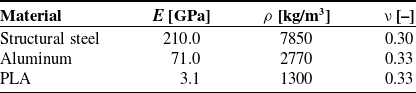
Material’s bulk mechanical properties in FEAs.

The prototype of the developed end-effector: (a) front view; (b) right view; (c) left view.

3.2. The mechanical design of the end-effector
To check the functionality and the proper stiffness of the conceived end-effector, the mechanical design was supported by finite element analyses (FEAs) developed in the Ansys Workbench® 2024 R2 environment. The 3D geometry of the end-effector was realized by the 3D CAD software Siemens Solid EdgeTM and exported into the FEM code. The modeled parts of the end-effector are the structural elements in steel, the load cells in aluminum, and the axial and radial supports in PLA. All the components are modeled as isotropic materials with the mechanical parameters reported in Table I. Although 3D-printed PLA exhibits anisotropic behavior due to the layer-by-layer manufacturing process, it was modeled as an isotropic material with average bulk mechanical properties [Reference El Mehtedi, Buonadonna, Carta, El Mohtadi, Marongiu, Loi and Aymerich18]. This simplification is commonly adopted in preliminary structural analyses to reduce computational cost, especially when the loading conditions do not induce significant stresses along the weak interlayer direction. Moreover, the parts were printed with 100% infill density to ensure the most homogeneous mechanical behavior. While this approach does not capture the full anisotropic behavior of printed PLA, it provides a reasonable approximation for the global structural response within the scope of this work.
The following settings were adopted in the model: automatic meshing with element size less than 3.0 mm (118,241 nodes and 71,389 elements), acceptable since an average skewness of 0.28; all tetrahedral elements; a fixed constraint at the flange attached to the wrist of the cobot (green-colored Fixed Support as shown in Fig. 4(a) to fix all nodes preventing motion); X, Y, and Z components of a concentrated remote force (simulating the cutting force) acting at the tip of the cutting tool (colored force vectors F, Fig. 4(a)) applied as a ramp force in the range (−4.0 to 4.0) N in the simulated time interval 0–1 s; a mass of 0.410 kg concentrated at the center of gravity of the Dremel (yellow point m, Fig. 4(a)); gravitational effects was included (standard earth gravity); bonded contacts among the load cells and the structural parts to represent the parts as rigidly connected, preventing any slip or detachment, while also reducing computational cost; nonlinear analysis by the Newton–Raphson method; auto time stepping controlled by the program. The applied forces are higher than the current experimental ones, as shown in Section 4. Several simulations were conducted to evaluate the total displacement for different values of the remote force components. Examples of the total displacement results are shown in Fig. 4(b) (Fx = −4.0 N, Fy = 4.0 N, and Fz = 0.0 N), and Fig. 4(c) (Fx = −2.0 N, Fy = 3.0 N, and Fz = 2.0 N). The maximum values of the deformation equal to 0.036 and 0.071 mm are comparable with the cobot repeatability (±0.05 mm), confirming that the end-effector stiffness is suitable for the purpose.
The numerical model of the end-effector: (a) mesh, fixed support (in green), remote force components (colored arrows F), and concentrated mass (point m in yellow); (b) the resulting total displacement in [mm] for Fx = −4.0 N, Fy = 4.0 N, and Fz = 0.0 N; (c) the resulting total displacement in [mm] for Fx = -2.0 N, Fy = 3.0 N, and Fz = 2.0 N.

3.3. Ground plate calibration
The ground plate calibration was necessary to find the current spatial orientation of the plate, refer its position to the cobot base reference system, and modify the 3D CAD model to adapt the tool path. The center of the ground plate was placed within the cobot workspace, slightly far from its boundary surface, at 500 mm from the center of the base of the cobot, along the -Y reference direction. An end-effector made of a mechanical dial test indicator (measurement range 0-10 mm, resolution ±0.01 mm) and its support (Fig. 5(a)) was assembled and mounted at the wrist of the cobot. Hence, by a procedure required by RoboDK® (Fig. 5(b)), three points of the upper surface of the plate were detected to build a virtual plane corresponding to the existing one. Finally, by manual control of the cobot, the coordinates of all the centers of the holes of the plate were acquired and imported into Solid EdgeTM and RoboDK® to create the virtual plate equipped with all the holes and referred to the cobot reference system.
The plate calibration procedure: (a) detail of the dial test indicator for detecting significant points; (b) detail of the RoboDK® interface for the plate calibration.

3.4. TCP calibration
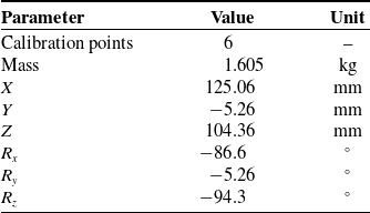
The self-learning procedure [Reference Siciliano, Villani and Oriolo32] in TMFlowTM identifies the TCP coordinates. It consists of positioning the center of the contouring tool’s lower surface in six poses and maintaining contact with the same object at the same point. The tip of a pin rigidly mounted in the center of the ground plate was used as the object. The software defines the position of the TCP with respect to the robot flange to compensate for it in subsequent movements. This phase is fundamental to ensure that the contouring machining tasks are not compromised. Fig. 6(a–f) shows the six points acquired. Later, the local reference system (placed at the center of the wrist of the cobot) was rotated to be aligned with the cobot reference system. Finally, the goodness of the calibration was verified by rotating the cobot around the TCP, demonstrating its stability without relative motion between the tip of the pin and the center of the contouring tool (see Video S1). Results are reported in Table II and added in RoboDK® for the tool path planning.
TCP calibration results.

TCP self-learning procedure: (a) first pose; (b) second pose; (c) third pose; (d) fourth pose; (e) fifth pose; (f) sixth pose.

3.5. Mechanical decoupling of the load cells: the cross-talk check
The load cells’ mechanical assembly and decoupling were evaluated before the cutting tasks were executed. Forces along the X–Y–Z directions were acquired by loading the contouring tool in the +X, −X, +Y, −Y, and +Z, −Z directions. Loads were manually applied by a laboratory spring dynamometer. The results, plotted in Fig. 7, show how the load cells are mechanically decoupled. For a maximum load of ±6 N along X, maximum force components of ±0.19 N along Y and ±0.38 N along Z were detected. Instead, for a force of ±7 N along Y, maximum force components of ±0.42 N along X and ±0.44 N along Z were detected. Finally, for a force of ±6 N along Z, maximum force components along X and Y of at most ±0.45 N and ±0.29 N, respectively, were detected. A not-perfect alignment of the dynamometer could justify the force components along the perpendicular directions of the applied force during the test execution. Results revealed that the unexpected forces are lower than 7.5% of the applied ones. For this reason, the three load cells were considered mechanically decoupled, with negligible cross-talk. Hence, the three-load cell system was considered suitable for the purpose.
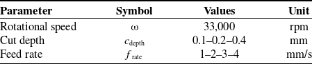
Cutting parameters adopted in the experimental activity.

Cross-talk between load cells by loading: (a) the first cell along +X and −X direction; (b) the second cell along +Y and −Y direction; (c) the third cell along +Z and −Z direction.

4. The experimental activity
A test campaign was carried out to evaluate the resulting surface roughness and cutting forces in contouring machining tasks for a given value of the rotational speed (ω) and different values of cut depth (c depth) and feed rate (f rate). The ω was set to 33,000 rpm (cutting speed of 621.72 m/min) for the reasons explained in ref. [Reference Scalera, Lozer, Giusti and Gasparetto29]. The set values of c depth and f rate are reported in Table III. Three trials for each c depth –f rate combination were performed for an overall amount of 36 tests. The latter was also carried out to check if the joint angles of the cobot were subjected to vibration that could compromise the contouring machining task. The tool path planning procedure was implemented.
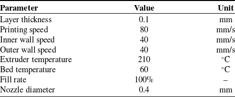
The machined workpieces were prototyped using a QIDI i-fast 3D printer, according to the printing settings reported in Table IV. A lacquer spray was applied to the print bed to prevent warping.
Printing settings adopted for the machined workpiece.

The hollow square-based prism in Fig. 8(a) was prototyped and adopted for tests. Each side of the prism was machined at a different frate (sides A, B, C, and D at 1, 2, 3, and 4 mm/s, respectively). In addition, each side was machined at three levels, with the cdepth decreasing from top to bottom (0.4, 0.2, and 0.1 mm, respectively), as shown in Fig. 8(b) (see Video S2). Examples of contouring tasks are shown in Fig. 8(b,c). The hollow geometry facilitates the measurement of the effective c depth to validate the positioning of the tool during machining, as shown in Fig. 8(d). After the first passage of the contouring tool, the c depth and the dimensions of the parts do not match the expected ones. This occurred due to a mismatch between the dimensions and the nominal positions of the workpieces. Starting from the second contouring task, the c depth is correct. For this reason, as explained in Section 4.4, the tool path planning procedure is improved by the vision job and a touch stop.
(a) 3D CAD model of the specimen for preliminary contouring tests; (b) front view of milling; (c) side view of milling; (d) measurement of the effective c depth after the contouring machining.

4.1. Evaluation of the surface roughness
Surface roughness measurements were carried out using the Leica M205A stereo zoom microscope, which provides optical magnification ranging from 7.8x to 160x and high-resolution imaging (around 1 µm). Average surface roughness values were extracted using the Leica Map®, which allows for the calculation of standard roughness parameters from the images obtained by a stereo microscope and provides accurate visualization of the surface morphology, as shown in Fig. 9. Raw workpieces show an average roughness (Ra
) of about 23 $\mu$
m. Hence, preliminary tests were conducted to evaluate which climb or up-cut contouring machining mode could improve the surface roughness. Fig. 9 shows the results for two tests conducted at ω, f
rate and c
depth equal to 33,000 rpm, 4 mm/s, and 0.4 mm, respectively. The best resulting surface roughness is 110.04
$\mu$
m. Hence, preliminary tests were conducted to evaluate which climb or up-cut contouring machining mode could improve the surface roughness. Fig. 9 shows the results for two tests conducted at ω, f
rate and c
depth equal to 33,000 rpm, 4 mm/s, and 0.4 mm, respectively. The best resulting surface roughness is 110.04 $\mu$
m for the climb contouring and 6.43
$\mu$
m for the climb contouring and 6.43 $\mu$
m for the up-cut contouring. The latter provides the best surface finishing, as found in the literature [Reference El Mehtedi, Buonadonna, Carta, El Mohtadi, Marongiu, Loi and Aymerich18], and was then adopted as a contouring machining mode in the following. The extracted surface’s height (y coordinates) was measured along the profile (x coordinates) shown in blue in Fig. 9. The examined profiles are reported in the same figures.
$\mu$
m for the up-cut contouring. The latter provides the best surface finishing, as found in the literature [Reference El Mehtedi, Buonadonna, Carta, El Mohtadi, Marongiu, Loi and Aymerich18], and was then adopted as a contouring machining mode in the following. The extracted surface’s height (y coordinates) was measured along the profile (x coordinates) shown in blue in Fig. 9. The examined profiles are reported in the same figures.
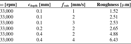
Table V reports some surface roughness values achieved from the twelve contoured surfaces for different combinations of the cutting parameters. The highest roughness value is 6.43 $\mu$
m for c
depth and f
rate equal to 0.4 mm and 4 mm/s, while the lowest is 1.52
$\mu$
m for c
depth and f
rate equal to 0.4 mm and 4 mm/s, while the lowest is 1.52 $\mu$
m for c
depth and f
rate set to 0.1 mm and 1 mm/s. The last combination was adopted for machining the profiles.
$\mu$
m for c
depth and f
rate set to 0.1 mm and 1 mm/s. The last combination was adopted for machining the profiles.
Up-cut contouring roughness results for different combinations of cutting parameters.

Roughness results. Surface color map, 3D view of the extracted surface, and the examined profile for (a) climb contouring and (b) up-cut contouring.

4.2. Evaluation of the cutting forces
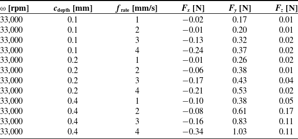
The load cells described in Section 3.1 acquired cutting forces during each test. The behavior of the forces is shown in Fig. 10, while the maximum forces along the X, Y, and Z axes are reported in Table VI to enhance the result clarity. The maximum measured value of one force component is about 1.0 N; the maximum absolute value of the force is about 1.1 N. The latter is lower than the adhesion force between the printing plate and the workpiece [Reference Płaczek33], suggesting that the proposed contouring machining robotic task avoids the detachment of the workpiece from the printing plate. Moreover, the maximum absolute value of the force is lower than the payload of the cobot. This item demonstrates that a cobot, more cost-effective and compact than an industrial robot, is a valid device within a new generation of large 3D printers. The higher f rate and c depth result in higher cutting forces because the single tooth of the tool must remove more material per unit time. The cutting forces on the planar machined surfaces are constant since the c depth is kept constant. However, there are increases or decreases, especially at the beginning or end of contouring, due to the presence of more or less material to be removed, respectively. As expected, the cutting force along the Z-direction is almost zero due to the peripheral contouring task. In the same direction, a force of at most 0.1 N is recorded for a c depth of 0.4 mm, as the tool teeth also lightly work in front contouring.
Maximum cutting force for different cutting parameter combinations in X, Y, and Z directions.

Cutting forces during tests for the c depth of: (a) 0.1 mm; (b) 0.2 mm; (c) 0.4 mm.

A modal test was performed to verify the main factor that allows achieving a low-vibration environment by identifying the natural frequencies of the machining system. Specifically, a SIEMENS SPM50 SCADAS system was employed to acquire signals from the modal hammer (ENDEVCO MODEL 2302-5, sensitivity 1.14 mV/N, frequency range up to 8 kHz) and the triaxial accelerometer (TLD356A32, sensitivity 10.2 mV/m/s2, measurement range ± 50 g, frequency range 1 ÷ 4000 Hz). The frequency response function was obtained by exciting the system along the X, Y, and Z directions, using an impulse excitation provided by the instrumented hammer, and measuring the acceleration on the end effector: five averages for each FRF were used. The resulting dynamic compliances are shown in Fig. 11(a).
(a) X (blue solid line), Y (black solid line), and Z (red solid line) dynamic compliances as a function of frequency; (b) PSD of accelerations for a contouring task with c depth = 0.4 mm and f rate = 4 mm/s.

The Power Spectral Density (PSD) of the accelerometer signal was analyzed during contouring operations under the most critical conditions, with a c depth of 0.4 mm and a f rate of 4 mm/s. The dynamic compliance is quite low above 300 Hz. Furthermore, the modal density (the number of modes in a frequency band) is also low, and the resonant peaks are well damped. This ensures that the vibrations of the end effector will remain low if the excitation spectrum is above 300 Hz, as expected for this machining operation. This is confirmed by observing Fig. 11(b), which shows that the excitation frequency associated with the specified contouring task is around 474 Hz.
In addition, Fig. 12 shows the behavior of the joint angles over time at the maximum c depth value (0.4 mm) and several frate values. Cutting forces do not generate joint vibrations (see details of some joints in the [0, 2] s time window in Fig. 12), showing that the overall stiffness of the cobot is suitable for the expected task. This experimental evidence confirms that the cutting operations are far from resonance peaks, thereby preventing vibration amplification. As a result, the system maintains stable dynamic behavior, directly contributing to achieving a smooth surface finishing with low roughness, as illustrated in Fig. 9.
Cobot’s joints for c depth = 0.4 mm and f rate: (a) 1 mm/s; (b) 2 mm/s; (c) 3 mm/s; (d) 4 mm/s.

4.3. Validating contouring machining tests
The toolpath planning procedure was improved to compensate for the mismatch between the workpiece’s nominal and current dimensions and orientations. To overcome this issue, a code was developed in the TMFlowTM environment to adapt the planned tool path to the real workpiece. The code algorithm expects a first step in which the robot moves to where the workpiece is placed (following the RoboDK® script file instructions). Hence, with the integrated robot 5MP color camera, the robot recognizes the position and orientation of the workpiece in the X–Y plane and adapts the planned tool path to the current orientation. Then, by a touch-stop operation, the robot vertically moves along the Z-axis to identify the workpiece’s current height, adjusts the Z height of the planned tool path, and moves the contouring tool to the starting point of the overall adapted tool path.
Figure 13(a,b) show the stage when the cobot is recognizing the orientation of the workpiece and when it is recognized, respectively (see Video S3). The blue arrows indicate the current positioning and orientation of the workpiece, and the red arrows refer to the nominal ones. A detail of the touch-stop operation is shown in Fig. 13(c).
Contouring trajectory compensation: (a) vision job during the orientation recognition of the workpiece; (b) vision job of the recognized orientation of the workpiece; (c) a detail of the touch-stop operation.

Three representative workpieces with circular, dodecagon, and curvilinear profiles were adopted to validate the contouring machining tasks. Fig. 14 shows the CAD model and the tool path (in green) with the relative recorded cutting forces and the joint angles of the cobot. Each test was conducted at a f rate set to 1 mm/s and c depth equal to 0.1 mm. The forces are consistent with those expected from the previously described tests: each force component is within the range ±0.3 N. The angular positions of the joints show that no vibrations are induced in the joints. The dimension measurement demonstrated the effectiveness of the tasks.
Validating test results. Workpiece geometry, cutting forces, and cobot joint angles for different profiles: (a) circular; (b) dodecagon; (c) curvilinear.

4.4. Discussion and comparison with related works
The developed end-effector was tested to validate no cross-talk between the load cells, allowing for independent cutting force measurement along the X, Y, and Z directions. Accurate calibration of the plane and TCP ensured precise tool alignment between simulations and real-world paths. Additionally, contouring operations were adapted to the current position and orientation of the workpiece using vision jobs and touch stops. The absence of observable vibrations in the cobot joints (Figs. 11, 14) provides experimental evidence of the cobot’s mechanical stability during contouring tasks. In the same way, Fig. 12 demonstrates that the modal density and the dynamic compliance along X, Y, and Z, around the excitation frequency (around 474 Hz) during the contouring task, are relatively low. This indicates that the end-effector exhibits sufficient damping and avoids resonance within the frequency range excited during machining. This behavior confirms that the end-effector and the cobot have enough stiffness for contouring operations. If the end-effector or cobot joints lacked adequate stiffness, the experimental data would be expected to show increased surface roughness or noticeable force oscillations. Since no such effects were observed, the tool can be considered effective and reliable for the intended application.
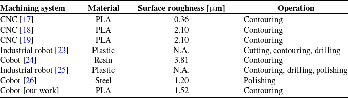
To evaluate the effectiveness of the proposed system, a comparative analysis was conducted with recent studies involving CNC machines, industrial robots, and cobots in machining operations, as summarized in Table VII. In ref. [Reference Lalegani Dezaki, Mohd Ariffin and Ismail17], a CNC machine was employed to process PLA material, like the approach adopted in this study. Although this work achieved a lower surface roughness of 0.36 $\mu$
m compared to the 1.52
$\mu$
m compared to the 1.52 $\mu$
m obtained in this study, the system presented here is more cost-effective, compact, and flexible. This topic highlights a significant trade-off between surface quality and system complexity. Studies refs. [Reference El Mehtedi, Buonadonna, Carta, El Mohtadi, Marongiu, Loi and Aymerich18, Reference El Mehtedi, Buonadonna, El Mohtadi, Loi, Aymerich and Carta19] also investigated CNC milling of PLA, but the cutting parameters and tools adopted led to surface roughness values of approximately 2.10
$\mu$
m obtained in this study, the system presented here is more cost-effective, compact, and flexible. This topic highlights a significant trade-off between surface quality and system complexity. Studies refs. [Reference El Mehtedi, Buonadonna, Carta, El Mohtadi, Marongiu, Loi and Aymerich18, Reference El Mehtedi, Buonadonna, El Mohtadi, Loi, Aymerich and Carta19] also investigated CNC milling of PLA, but the cutting parameters and tools adopted led to surface roughness values of approximately 2.10 $\mu$
m, higher than those achieved with the proposed system. These results reinforce the effectiveness of the present approach, which performs favorably even when compared to more established CNC technologies working on the same material. In ref. [Reference Iglesias, Sebastiàn and Enrique23], an industrial robot was adopted for various manufacturing tasks, including cutting, contouring, and drilling. However, the study does not report quantitative data regarding cutting forces or surface roughness, which limits direct comparison with this work. The study focuses more on the robot’s operational versatility rather than its precision or stability. In the same field, a comprehensive literature review [Reference Makulavičius, Petkevičius, Rožėnė, Dzedzickis and Bučinskas25] discusses the limitations of using industrial robots in certain machining operations, particularly regarding the material removal rate. Other studies have employed cobots in different machining contexts. For instance, ref. [Reference Perez-Ubeda, Gutiérrez, Stanisic and Lluch-Cerezo24] presents milling operations on resin-based materials, while ref. [Reference Yuzhang. and Qingsong26] investigates the use of a cobot for polishing steel. In the latter, a force control system was implemented to ensure accurate path tracking over complex geometries, demonstrating advancements in adaptive contact-based processes. In the present study, the use of vision-based and touch-stop compensation allowed adjustment of the tool path according to the current position and orientation of the workpiece, an approach rarely addressed in the literature. Combined with a rigid and mechanically stable end-effector, these strategies enabled low-vibration operations and consistent surface quality under low-force conditions typical of polymer machining. Overall, the proposed system distinguishes itself in performance and balanced adaptability, accuracy, and cost integration. This approach effectively bridges the gap between high-end CNC machines and more accessible robotic solutions for contouring 3D-printed MEX components.
$\mu$
m, higher than those achieved with the proposed system. These results reinforce the effectiveness of the present approach, which performs favorably even when compared to more established CNC technologies working on the same material. In ref. [Reference Iglesias, Sebastiàn and Enrique23], an industrial robot was adopted for various manufacturing tasks, including cutting, contouring, and drilling. However, the study does not report quantitative data regarding cutting forces or surface roughness, which limits direct comparison with this work. The study focuses more on the robot’s operational versatility rather than its precision or stability. In the same field, a comprehensive literature review [Reference Makulavičius, Petkevičius, Rožėnė, Dzedzickis and Bučinskas25] discusses the limitations of using industrial robots in certain machining operations, particularly regarding the material removal rate. Other studies have employed cobots in different machining contexts. For instance, ref. [Reference Perez-Ubeda, Gutiérrez, Stanisic and Lluch-Cerezo24] presents milling operations on resin-based materials, while ref. [Reference Yuzhang. and Qingsong26] investigates the use of a cobot for polishing steel. In the latter, a force control system was implemented to ensure accurate path tracking over complex geometries, demonstrating advancements in adaptive contact-based processes. In the present study, the use of vision-based and touch-stop compensation allowed adjustment of the tool path according to the current position and orientation of the workpiece, an approach rarely addressed in the literature. Combined with a rigid and mechanically stable end-effector, these strategies enabled low-vibration operations and consistent surface quality under low-force conditions typical of polymer machining. Overall, the proposed system distinguishes itself in performance and balanced adaptability, accuracy, and cost integration. This approach effectively bridges the gap between high-end CNC machines and more accessible robotic solutions for contouring 3D-printed MEX components.
5. Conclusions
A robotic station for contouring machining of 3D-printed MEX components was designed, implemented, and validated. The Omron TM5-700 cobot was equipped with a new end-effector made of a commercial hobbyist contouring tool and a three-load cell system.
The end-effector was designed and numerically simulated. Its stiffness was achieved to be suitable for the given purpose during the experimental activity and the TCP calibration check. Moreover, the three load cells were demonstrated to be mechanically decoupled. A vision job and touch-stop operation improved the proposed tool path planning procedure and made it more effective. It compensates for the mismatch between the workpiece’s nominal and current dimensions and orientations.
A campaign of tests demonstrated that the surface finish improved with up-cut contouring machining. The highest rotational speed (33,000 rpm), the smallest cut depth (0.1 mm), and the smallest feed rate (1 mm/s) yielded the best results. For higher values of the cutting parameters, the cutting forces increase. Nevertheless, the maximum measured force is lower than the adhesion force between the workpiece and the printing plate. This means that contouring machining avoids detaching the workpiece from the plate. Moreover, cutting forces did not transmit vibrations to the cobot joints. Despite using a hobbyist tool, whose performance is worse than an industrial tool’s, the results show that the adopted cobot could be a viable alternative to CNC machines.
In future work, advanced optimization techniques involving a complete design of experiments, such as the Taguchi method, will be considered to enable a more systematic and comprehensive cutting parameter optimization. This approach will allow a deeper exploration of the effects of cutting parameters and potentially lead to further improvements beyond the preliminary findings presented here. The focus will be on minimizing the surface roughness of 3D-printed components and extending the analysis to different materials and workpieces machined directly on the printing plate. Moreover, the use of the load cells will be explored for real-time feedback control during contouring operations. This approach aims to maintain a constant cutting force along the tool path, thereby enhancing the consistency and quality of the machining process.
Comparison with related works.

Supplementary material
The supplementary material for this article can be found at https://doi.org/10.1017/S0263574725102567.
Acknowledgements
The authors thank Engs. Francesco Di Donato and Alessandro Sorgi, for their precious help during the experimental activity.
Author contribution
MGA, JB, WDA, EM, and NS conceived and designed the study, conducted data gathering, performed formal analyses and data curation, wrote the article, and revised and refined the article. MGA supervised the project. MGA, JB, and WDA provided the funding.
Financial support
This work was funded by MIMIT Prog. MASSIVE n. F/310247/03/X56-CUP:B19J23000980005-COR:16046879.
Competing interests
The authors declare no conflicts of interest exist.
Ethical approval
Not applicable.


 Open access