


1. Introduction
The growing global demand for assistive technologies highlights the critical role of innovative solutions in addressing societal challenges. Currently, 15% of the global population experiences physical disabilities, emphasizing the need for tools that promote autonomy and social inclusion. Moreover, aging populations are becoming a pressing concern, particularly in Western countries, where it is projected that 56.7% of the population will be over the age of 65 by 2050. On a global scale, the number of individuals aged 60 and above is expected to reach 2.1 billion by the same year. To address these demographic shifts, advancements in exoskeleton technology are essential for enabling older adults and individuals with disabilities to maintain independence, contribute to the workforce, and mitigate occupational health risks. These solutions are integral not only for improving quality of life but also for fostering social inclusion and addressing broader societal needs.
Exoskeletons offer a viable solution by redistributing load, reducing muscle strain, and enhancing endurance. These devices are designed to optimize human performance, particularly in environments involving repetitive or physically demanding tasks. With advances in materials science, control systems, and biomechanical modeling [Reference Sarajchi and Sirlantzis1], exoskeletons have evolved into a sophisticated technological solution aimed at reducing workplace fatigue, minimizing injuries, and increasing productivity [Reference Wang, Liang, Li, Gong, Deng, Hu, Zhang and Sun2].
The design of effective upper-limb exoskeletons involves the intricate understanding of human biomechanics of connected parts and joints [Reference Zeiaee, Soltani-Zarrin, Langari and Tafreshi3]. These joints not only exhibit multi-degree-of-freedom motion but are also critical to executing precise tasks and maintaining ergonomic safety. Misalignment between the exoskeleton and the user’s anatomical joints can lead to discomfort, inefficiency, and potential injury. As such, modern exoskeleton development employs advanced biomechanical modeling, adaptive mechanisms, and user-centered design principles to ensure optimal alignment and intuitive usability [Reference Ruiz, Rocon and Forner-Cordero4–Reference Rahman, Rahman, Ochoa-Luna, Saad, Kenné and Archambault6].
Innovations in actuator and sensor technologies have further propelled the field, enabling real-time adaptability of exoskeletons to the user’s movements [Reference Yang, Zhang and Fu7]. State-of-the-art control algorithms, coupled with machine learning techniques, offer systems that are not only responsive but also predictive, effectively enhancing the human–machine interaction. These systems rely on lightweight yet robust materials such as carbon fiber and advanced polymers, which ensure both durability and portability. As a result, exoskeletons are becoming increasingly versatile, capable of supporting subjects across various applications, from heavy lifting to precision assembly tasks [Reference Tiboni, Borboni, Vérité, Bregoli and Amici8, Reference Aggogeri, Borboni, Faglia, Merlo and De Cristofaro9]. Recent advancements in biomechanical modeling have shed light on the intricacies of human joint motion, enabling the development of exoskeletons that closely mimic natural movement. The shoulder joint’s ball-and-socket structure allows for a high degree of rotational freedom, making it difficult to replicate in exoskeletons. Studies have focused on optimizing torque and motion to ensure natural movement and reduce muscle strain during tasks like lifting [Reference Arefeen and Xiang10, Reference Arefeen, Xia and Xiang11]. Elbow and wrist joints involve both rotational and translational movements, requiring precise alignment in exoskeleton design to prevent misalignment and compensatory movements that could lead to strain or injury. Techniques such as screw theory and kinematic analysis have been employed to model these joints accurately, ensuring that exoskeletons can mimic the natural motion patterns of the human arm [Reference Gao, Lang, Shen and Zhao12, Reference Głowiński, Krzyżyński, Pecolt and Maciejewski13]. For lower limb exoskeletons, integrating muscle biomechanics into design and control has been emphasized to improve human-exoskeleton interaction [Reference Sarajchi, Al-Hares and Sirlantzis14]. This includes using electromyography (EMG) and mechanomyography (MMG) to predict joint torque and optimize assistive strategies, thereby enhancing the synergy between human and machine [Reference Al-Quraishi, Elamvazuthi, Tang, Al-Qurishi, Parasuraman and Borboni15, Reference Cardona and Cena16]. Advanced modeling techniques, such as inverse dynamics and optimization algorithms, are used to predict and control joint torques, minimizing muscle activation and improving the efficiency of exoskeletons during dynamic tasks [Reference Vatsal and Purushothaman17]. Misalignment at any of these joints can lead to compensatory movements, increasing the risk of strain and injury.
Advancements in materials science have significantly contributed to the development of lightweight and durable exoskeletons. The integration of carbon fiber-reinforced polymers (CFRP) with aluminum components has been explored to create lightweight yet strong exoskeletons. This combination allows for the fabrication of multi-material components that are durable and resistant to stress, as demonstrated in robotic exoskeletons [Reference Pappas and Botsis18, Reference Yi, Fu, Yang, Liao and Guo19]. Materials such as PETG, TPU, and PLA are used in 3D printing to create semi-rigid and flexible components for exoskeletons. These materials contribute to improved human–robot interaction and support, particularly in knee exoskeletons [Reference Rivera and Sharifi20]. Inspired by natural exoskeletons, biomimetic materials offer multifunctional properties such as strain stiffening and enhanced friction, which are beneficial for soft robotics and wearables [Reference Ebrahimi, Ali, Stephen and Dharmavaram21]. Additionally, crab shell-derived materials like chitin and chitosan are being explored for their strength and biodegradability in medical applications [Reference Idoko, Bashiru, Olola, Enyejo, Nbéu and Manuel22]. The use of flexible materials at joint interfaces allows for a more natural range of motion, improving user comfort [Reference Yi, Fu, Yang, Liao and Guo19]. Pneumatic air muscles and artificial muscles provide lightweight and flexible actuation, mimicking natural muscle movements. They are used to enhance the performance and comfort of exoskeletons, particularly in applications requiring heavy lifting [Reference Meshram, Bashir, Thange, Siddiqui and Mirkar23, Reference Dong, Zhang and Liu24].
Despite these advances, challenges persist in the alignment of exoskeletons with the biomechanical diversity of upper limb motions. This paper introduces a novel exoskeleton prototype that incorporates innovative design strategies to address alignment issues. Building upon previous research [Reference Borboni, Arbore and Elamvazuthi25, Reference Borboni, Arbore and Elamvazuthi26], the proposed exoskeleton features an articulated system for joint misalignment correction and employs a cost-effective design. This includes strategic placement of motors in the pelvic region to reduce upper-body stress, advanced transmission systems to optimize power delivery [Reference Moghayedi, Cifuentes, Munera and Sarajchi27], and adaptive components for enhanced user comfort. By integrating modern materials and intelligent control systems, the prototype offers a lightweight, portable solution tailored to the needs of subjects.
2. Problem definition
This study is devoted to facilitating functional upper limb joint movements with exoskeleton joints, which are less flexible [Reference Negrini, Piovanelli, Amici, Cappellini, Bovi, Ferrarin, Zaina and Borboni28]. Human joints, made of bones, ligaments, tendons, cartilage, and synovial fluid, absorb shock, distribute load, and allow for a wide range of motions, unlike mechanical joints, which are designed for specific motions and lack self-repair and sensory feedback [Reference Benjamin and Ralphs29]. Mechanical replication is difficult due to human joint materials’ unique properties. Anthropometric variability due to ethnicity, gender, lifestyle, and age affects upper limb dimensions and biomechanical properties, requiring exoskeleton design adjustments [Reference Bhat, Jindal and Acharya30].
The functional action of the upper limb is mainly associated with manipulating objects in space and can be broken down into a sequence of operations: strategy planning, preparation for movement, approach to the interaction zone, interaction, and return to the rest position. The first operation is all mental; the second operation is to find the right posture and prepare the musculoskeletal system for action. Especially during the subsequent actions, continuous control and replanning of the movement always take place. The approach is a rather light operation. Interaction is the most mechanically onerous operation. And then the return to rest is again a light operation. It is assumed that the human subject has motion planning skills and has enough mobility to perform light operations independently but may have difficulty performing interaction operations, so the proposed application focuses on this phase, particularly on lifting rather heavy objects, but not excessively heavy ones to produce skeletal damage. The lifting operation is assumed to be performed on a motion plane. Since the subject can perform all other operations independently, light movements can be decoupled from mechanically onerous movements. This functional decoupling leads to a need for exoskeleton assistance only in the lifting plane. In this way, there is a simplification of design without affecting the effectiveness of the assisting action.
To accurately discern the lifting action executed by the human body and to inform the design of an exoskeleton that offers support without inflicting injury, it is essential to thoroughly examine the physiology of the human body and its limitations.
The upper limb kinematic chain comprises multiple joints, requiring a comprehensive model that includes the shoulder complex (along with the scapula) and the thoracic spine for accurate representation. The forward kinematics model assumes the Denavit and Hartemberg (DH) convention to express joint relations and movements between adjacent rigid body segments. Transformations are described using matrices that determine segment positions and orientations in space. Key anatomical components include the thoracic spine, which influences scapular orientation through flexion/extension θspine,x, lateral flexion θspine,y, and rotation θspine,z; the scapulothoracic joint, enabling movements such as elevation/depression θscapula,y, protraction/retraction θscapula,z, and rotation θscapula,x; the glenohumeral joint, responsible for flexion/extension θshoulder,x, abduction/adduction θshoulder,y, and internal/external rotation θshoulder,z; the elbow, facilitating flexion/extension θelbow and limited axial rotation; the radioulnar joint, enabling forearm pronation/supination θforearm; and the radiocarpal joint, which allows wrist flexion/extension θwrist,x and radial/ulnar deviation θwrist,z. The adopted DH parameters, starting from the L5 vertebra, are indicated in Table I.
DH parameters for the upper limb of the human body during lifting

Table I Long description
The table presents Denavit-Hartenberg (DH) parameters for the upper limb joints during lifting. It includes 13 rows and 4 columns. The columns are labeled as follows: Joint, θi, di, ai, and αi. Each row corresponds to a specific joint and lists the associated parameters. Row 1: Joint 1, θi spine,x, di 0, ai 0, αi π/2. Row 2: Joint 2, θi spine,y, di 0, ai 0, αi π/2. Row 3: Joint 3, θi spine,z, di dspine, ai aspine, αi 0. Row 4: Joint 4, θi scapula,y, di 0, ai 0, αi π/2. Row 5: Joint 5, θi scapula,z, di 0, ai 0, αi π/2. Row 6: Joint 6, θi scapula,x, di dscapula, ai ascapula, αi 0. Row 7: Joint 7, θi shoulder,x, di 0, ai 0, αi π/2. Row 8: Joint 8, θi shoulder,y, di 0, ai 0, αi π/2. Row 9: Joint 9, θi shoulder,z, di dshoulder, ai ashoulder, αi 0. Row 10: Joint 10, θi elbow, di 0, ai aelbow, αi 0. Row 11: Joint 11, θi wrist,x, di 0, ai 0, αi π/2. Row 12: Joint 12, θi wrist,z, di 0, ai 0, αi 0. Row 13: Joint 13, θi forearm, di 0, ai aforearm, αi 0.
It is essential to take into account the scapulohumeral rhythm, which outlines the timing of movement at the glenohumeral and scapulothoracic joints during shoulder elevation. The initial phase involves a setting stage: the first 30 degrees of shoulder elevation, during which the movement primarily occurs at the glenohumeral joint. Then, in this process, the glenohumeral and scapulothoracic joints operate together, maintaining approximately a 2:1 ratio of movement between the glenohumeral and scapulothoracic joints. This ratio varies across different subjects [Reference Inman, Saunders and Abbott31], and factors such as aging or pathologies can affect it.
Each joint examined has structural limitations pertaining to the range of motion (ROM) that must not be surpassed to prevent injuries. At first, one may cautiously examine specific limit values documented in the literature. The thoracic spine permits approximately 30° of flexion/extension, 30° of lateral flexion, and 45° of axial rotation. The scapulothoracic joint allows for elevation up to 50°, protraction around 25°, and upward rotation reaching 60°. The shoulder exhibits a wide range of motion, with flexion and abduction reaching approximately 180° each, and rotation extending to 90°. We must consider that only part of this movement is due to the glenohumeral joint, which contributes 100°–120° to flexion and 90°–120° to abduction. The elbow facilitates flexion up to 150°, while the radioulnar joint supports forearm pronation and supination within a combined range of 160°. Lastly, the wrist accommodates flexion and extension of approximately 80° and radial/ulnar deviation of about 30°.
Although the analysis presented here may initially seem precise, it exhibits several limitations that require further consideration to accurately define the behavior of the exoskeleton. The spine is considered a single rigid body. Then, a primary limitation pertains to the inherent complexity of certain joints; for instance, in examining the shoulder, it is evident that it comprises at least four distinct joints: the sternoclavicular, acromioclavicular, scapulothoracic, and glenohumeral joints. This may result in discrepancies in the kinematic relationships between representation and real behavior. Furthermore, the musculoskeletal system, particularly the joints, demonstrates characteristics of finite and non-linear stiffness that differ among individuals and can fluctuate within the same day for a single individual. This introduces a factor of challenging predictability that can be addressed, for instance, by further constraining the nominal limits of the ROM and tailoring the designs of exoskeletons for healthy individuals or those with medical conditions.
All these variabilities can be evaluated on a statistical basis, but each individual subject has its own specific peculiarities. Therefore, it is not possible to develop an exoskeleton that is generally suitable for everyone without considering the need for individual adjustments, either before operation (mounting) or during operation (self-aligning).
3. Materials and methods
3.1. Anthropometric analysis measures
The U.S. Army ANSUR II Database was adopted in this work. It is titled “Anthropometric Survey of U.S. Army Personnel” and offers detailed information on the anthropometric measurements of the target population. The 2012 public update encompasses a thorough collection of publicly accessible data regarding body size and shape, featuring 93 measurements from over 6,000 U.S. military adults, comprising 4,082 men and 1,986 women. The dimensions in question are contingent upon the ethnicity of the subjects under analysis: the predominant group consists of Caucasians, with ethnic subgroups represented in accordance with their respective distribution [Reference Kang, Jeon, Kim, Kim, Jung and Lee32].
Anthropometric dimensions exhibit a Gaussian distribution within the reference population, with the reported data characterized by mean values and standard deviations, thereby facilitating reference and size assumptions. The limited, albeit extensive, variety of multiethnicity is not the sole factor contributing to variability: focusing exclusively on military subjects suggests that the data collected pertains solely to adults in good physical condition. This indicates that the dimensions of the designed exoskeleton are likely to be incompatible with children and individuals with obesity or general shape deformities. Considering these limitations and in relation to the reported upper limb model, the parameter sizes for the upper limb may be established as equivalent to the length of the radial styloid and the acromio-radial length, respectively.
3.2. Exoskeleton design
3.2.1. Distal mechanism
A kinematic diagram of the proposed system is shown in Figure 1, where the purple joints represent the human joints, and the gray joints represent the exoskeleton joints. The exoskeleton is moved by the human subject through the movements indicated by the red arrows during the approach to the interaction and the return to the resting zone. Once the interaction plane is defined, the exoskeleton acts mechanically with the movements indicated by the blue arrows in the interaction plane. The motorized rotary hinges D and A of the exoskeleton are made with ball joints to allow some movements of the human subject, e.g., forearm pronosupination, and to compensate for some mounting errors. In addition, the motion of the motorized hinges is transferred to the human subject through two connecting-rod-crank mechanisms with a carriage axis shown in green that allows the transfer of mechanical actions perpendicular to the body segment on which it is mounted while avoiding shear actions that would cross the joints.
Kinematic diagram of the distal part of the proposed exoskeleton.

Figure 1 Long description
A kinematic diagram of the distal part of the proposed exoskeleton. The diagram includes various labeled components connected by black lines, representing joints and links. Key components include cylindrical joints labeled A, B, D, E, and cylindrical segments labeled F, H, and C. Spherical elements labeled G, N, and M are also present. Arrows in blue, red, and green indicate possible movements or rotations at specific joints. The overall structure suggests a mechanical system designed to mimic or assist human limb movements.
In the following, for the sake of simplicity, we will consider that the interaction movement (the lifting) acts in a plane parallel to the sagittal plane (a vertical plane), as shown in Figure 2, which reports a single connecting-rod-crank mechanism with two possible configurations that acts on the forearm, and it will be thoroughly studied, while the analysis of the analogous mechanism that acts on the arm will be omitted for the similarity of the two mechanisms.
Scheme of a single connecting-rod-crank mechanism in two acceptable configurations.

Figure 2 Long description
Panel A: Diagram of a single connecting-rod-crank mechanism. The mechanism includes a connecting rod labeled l1, a crank labeled l2, and points labeled B1, A, and Q1. The diagram shows angles β1, φ1, and γ, with distances dx, dy, d, x, and ξ1. Panel B: Diagram of another configuration of a single connecting-rod-crank mechanism. The mechanism includes a connecting rod labeled l2, a crank labeled l1, and points labeled B2, A, and Q2. The diagram shows angles β2, φ2, and γ, with distances dx, dy, d, x, and ξ2.
Consider the planar mechanism in Figure 2, modeled as a multibody system of rigid bodies connected by ideal joints. In Q1, there is a prismatic joint in the plane on a straight guide in the direction ξ1, assumed ideal in the absence of friction. Q1 allows for single relative mobility, translation along the guide, and prevents both translation normal to the guide and relative rotation between the two constrained elements.
Starting from the equation of motion of the system with holonomic constraints in Lagrangian formulation with multipliers (1), it is possible to isolate the contribution of the slider by introducing the constraints in Q1 through a local basis of the guide represented by the unit vectors t and n, which represent, respectively, the tangential and normal actions to the direction of sliding. In particular, the constraints imposed by Q1 (2) entail belonging to the linear guide and the absence of relative rotation.
 \begin{equation}\mathbf{M}(\mathbf{q})\,\ddot{\mathbf{q}}+\mathbf{h}(\mathbf{q},\dot{\mathbf{q}})=\mathbf{Q}(\mathbf{q},\dot{\mathbf{q}},t)+\mathbf{J}_{c}(\mathbf{q})^{T}\,\boldsymbol{\lambda }\end{equation}
 \begin{equation}\boldsymbol{\phi }_{{Q_{1}}}(\mathbf{q})=\left[\begin{array}{c} \mathbf{n}^{T}\left(\mathbf{r}_{{Q_{1}}}(\mathbf{q})-\mathbf{r}_{P}\right)\\ \theta _{rel,{Q_{1}}}(\mathbf{q}) \end{array}\right]=\mathbf{0}\end{equation}
The constraints impose the belonging of point Q1 to the guide (zero normal component) and the absence of relative rotation (2). The constraint reactions of the slider enter the generalized equations as in (3), where λQ1 is the vector of multipliers and the subscripts n and m indicate, respectively, the normal and rotational constraints.
 \begin{equation}\mathbf{Q}_{{Q_{1}}}(\mathbf{q})=\mathbf{J}_{{Q_{1}}}(\mathbf{q})^{T}\,\boldsymbol{\lambda }_{{Q_{1}}},\quad \quad \mathbf{J}_{{Q_{1}}}(\mathbf{q})=\frac{\partial \boldsymbol{\phi }_{{Q_{1}}}}{\partial \mathbf{q}},\quad \quad \boldsymbol{\lambda }_{{Q_{1}}}=\left[\begin{array}{c} \lambda _{n}\\ \lambda _{m} \end{array}\right]\end{equation}
The virtual work is zero in ideal constraints, so the only admissible relative virtual motion in Q1 is a translation along t, as expressed by the virtual twist in (4). The reaction of the slider is described by the planar wrench wQ1, which for ideal constraints must satisfy (5) for every admitted virtual motion. Substituting (4) into (5), the moment term does not contribute, i.e., δθrel is equal to zero, and the condition ${\boldsymbol{F}}_{\boldsymbol{Q}_{\mathbf{1}}}^{\boldsymbol{T}}\boldsymbol{t}=\mathbf{0}$
is obtained, meaning the constraint force is orthogonal to the guide.
${\boldsymbol{F}}_{\boldsymbol{Q}_{\mathbf{1}}}^{\boldsymbol{T}}\boldsymbol{t}=\mathbf{0}$
is obtained, meaning the constraint force is orthogonal to the guide.
 \begin{equation}\delta \mathbf{V}_{rel,{Q_{1}}}=\left[\begin{array}{c} \delta \mathbf{r}_{rel,{Q_{1}}}\\ \delta \theta _{rel,{Q_{1}}} \end{array}\right]=\left[\begin{array}{c} \mathbf{t}\,\delta \xi _{1}\\ 0 \end{array}\right]\end{equation}
 \begin{equation}\delta W_{{Q_{1}}}={\mathbf{w}}_{Q_{1}}^{T}\,\delta \mathbf{V}_{rel,{Q_{1}}}=0,\quad \quad \mathbf{w}_{{Q_{1}}}=\left[\begin{array}{c} \mathbf{F}_{{Q_{1}}}\\ M_{{Q_{1}}} \end{array}\right]\end{equation}
Equivalently, the structure of the wrenches transmissible by the constraint Q1 is expressed by (6): the slider can generate only a normal force and a constraint moment but no tangential force. The component parallel to the guide (responsible for tension/compression along the slider) is therefore the projection $\boldsymbol{F}_{\parallel }$
, which is identically zero as shown in (7). Therefore, in the absence of friction or actuation along the guide, no parallel force action to ξ1 can be transmitted at Q1.
$\boldsymbol{F}_{\parallel }$
, which is identically zero as shown in (7). Therefore, in the absence of friction or actuation along the guide, no parallel force action to ξ1 can be transmitted at Q1.
 \begin{equation}\mathbf{w}_{{Q_{1}}}={\mathbf{A}}_{Q_{1}}^{T}\,\boldsymbol{\lambda }_{{Q_{1}}},\quad \quad \mathbf{A}_{{Q_{1}}}=\left[\begin{array}{c@{\quad}c} \mathbf{n}^{T} & 0\\ 0\,0 & 1 \end{array}\right]\,\Rightarrow \,\mathbf{F}_{{Q_{1}}}=\lambda _{n}\,\mathbf{n},\,\,M_{{Q_{1}}}=\lambda _{m}\end{equation}
 \begin{equation}F_{\parallel }=\mathbf{t}^{T}\mathbf{F}_{{Q_{1}}}=\mathbf{t}^{T}(\lambda _{n}\mathbf{n})=\lambda _{n}\,(\mathbf{t}^{T}\mathbf{n})=0\end{equation}
With reference to Figure 2: G is the position of the elbow; A is the position of the exoskeletal fixed revolute joint; B is the position of the exoskeletal mobile joint; Q is the position of the prismatic joint between the exoskeleton and the forearm; a is the length of the forearm GP; l is the length of the exoskeleton connecting rod BQ; m is the length of the exoskeleton crank AB; $\xi$
is the distance of Q with respect to the wrist P;
$\xi$
is the distance of Q with respect to the wrist P; $\beta$
is the counterclockwise rotation angle of m with respect to the vertical direction;
$\beta$
is the counterclockwise rotation angle of m with respect to the vertical direction; $\varphi$
is the counterclockwise rotation angle of l with respect to the forearm’s direction;
$\varphi$
is the counterclockwise rotation angle of l with respect to the forearm’s direction; $\gamma$
is the counterclockwise rotation angle of a with respect to the horizontal direction (−90° in the resting configuration along the y direction and + 45° in the configuration of maximum flexo-extension). The misalignment between the elbow hinge G and the exoskeleton hinge A is described by the scalar terms dx and dy.
$\gamma$
is the counterclockwise rotation angle of a with respect to the horizontal direction (−90° in the resting configuration along the y direction and + 45° in the configuration of maximum flexo-extension). The misalignment between the elbow hinge G and the exoskeleton hinge A is described by the scalar terms dx and dy.
Four possible configurations of the selected mechanism.

Figure 3 Long description
A diagram illustrating four possible configurations of a mechanism used in upper-limb exoskeletons. The diagram shows interconnected joints and links labeled with various parameters such as angles, lengths, and forces. Key components include points A1, B1, B2, and P, with labels indicating angles (alpha, beta, phi, gamma) and lengths (l1, l2, l3, l4). The diagram also includes annotations for masses (m1, m2) and forces (Q1, Q2). The overall structure depicts the relationships and movements between these components, highlighting the complexity of biomechanical modeling in exoskeleton design.
With the allowed preselected region of misalignment, the rotary crank mechanism is theoretically available in four generally different configurations depending on the initial value of $\varphi$
and of
$\varphi$
and of $\beta$
(and/or of
$\beta$
(and/or of $\alpha$
), as shown in Figure 3; thus, a conventional constraint was initially imposed on the initial value of
$\alpha$
), as shown in Figure 3; thus, a conventional constraint was initially imposed on the initial value of $\varphi$
associated with
$\varphi$
associated with $\gamma$
equal to −90°, as shown in (8), to reduce encumbrance of the exoskeleton in the interacting area.
$\gamma$
equal to −90°, as shown in (8), to reduce encumbrance of the exoskeleton in the interacting area.
 \begin{equation}0\lt \varphi \lt 90^{\circ}\end{equation}
With reference to Figure 2, the closure equation of the system can be described by (9), which leads to the scalar expression (10) that represents a relation between the forearm and the exoskeleton kinematics.
 \begin{equation}(B-A)+(Q-B)=(G-A)+(Q-G)\end{equation}
 \begin{gather} [sin\gamma (dx-l\cdot cos\varphi )+cos\gamma (l\cdot sin\varphi -m-dy)]\cdot t^{2}+2m\cdot sin\gamma \cdot t\nonumber\\ +\, sin\gamma (dx-l\cdot cos\varphi )+cos\gamma (l\cdot sin\varphi +m-dy)=0 \\ t=\beta /2 \nonumber\end{gather}
To characterize the system’s appropriate behavior, it is beneficial to establish certain constraint conditions that can be classified into four distinct categories: obstruction conditions, working area conditions, anthropometric conditions, and kinematic conditions.
Obstruction conditions are designed to minimize the invasiveness of the exoskeleton. In this instance, the maximum allowable misalignment between A and G was established at 10 cm in both the x and y axes within the designated spatial area “above” and “behind” the elbow (dx > 0, dy < 0) (11).
 \begin{align} dx = 0\div 10\,\mathrm{cm}; \qquad dy = -10\div 0\,\mathrm{cm}; \end{align}
Working area conditions are devoted to respect the natural ROM of human joints and to realize the functional action (lifting in this case study). The crank mechanism solution permits four distinct configurations based on the fixed value of $\varphi$
throughout the flexo-extension range and the initial values of
$\varphi$
throughout the flexo-extension range and the initial values of $\alpha$
and/or
$\alpha$
and/or $\beta$
. The limitations on the range of
$\beta$
. The limitations on the range of $\varphi$
result in the examined crank mechanism having only two specific configurations: one with acute values and another with obtuse values of the initial angle
$\varphi$
result in the examined crank mechanism having only two specific configurations: one with acute values and another with obtuse values of the initial angle $\beta$
0, as just mentioned. At this juncture, the total circumferences delineated by the end effector of the crank mechanism for the two examined sub-configurations must consistently encompass point G, indicating that the exoskeleton’s components must possess adequate length to consistently reach the limb’s interface, regardless of the degree of misalignment. Analytically, imposing this condition equates to asserting that the combined length of the crank and connecting rod exceeds the permissible maximum misalignment (12).
$\beta$
0, as just mentioned. At this juncture, the total circumferences delineated by the end effector of the crank mechanism for the two examined sub-configurations must consistently encompass point G, indicating that the exoskeleton’s components must possess adequate length to consistently reach the limb’s interface, regardless of the degree of misalignment. Analytically, imposing this condition equates to asserting that the combined length of the crank and connecting rod exceeds the permissible maximum misalignment (12).
 \begin{equation}m+l\gt d_{max}=(\sqrt{dx^{2}+dy^{2}})_{max}=\sqrt{200}\ \mathrm{cm}\end{equation}
Furthermore, the constraint on the run distance accessible to the slider of the prismatic joint (point Q) was set as in (13), ensuring that Q remains in contact with the forearm without surpassing the wrist limit during the whole lifting action described by the angle γ.
 \begin{align} 0\leq \xi \leq a; \qquad \forall \gamma \in [-\pi /2,\pi /4]\end{align}
Utilizing the auxiliary relative frame of reference x′y′ with the origin at the elbow point G, y′ aligned with the forearm link, and x′ perpendicular to it in the sagittal plane towards the exoskeleton mechanism, the $\xi$
parameter can be expressed as in (14), where
$\xi$
parameter can be expressed as in (14), where $y'_B$
denotes the y′ coordinate of point B relative to the x′y′ frame.
$y'_B$
denotes the y′ coordinate of point B relative to the x′y′ frame.
 \begin{equation}\xi =a+y\mathrm{'}_{B}-l\cdot cos\varphi\end{equation}
To dimension the overall system and meet the target population’s needs with a singular physical solution, the aforementioned inequality for the slider’s run can be resolved by assessing the $\xi$
parameter under the most critical circumstances, leading to the application of the dimensioning conditions (15) to the two resultant sub-configurations of the crank mechanism.
$\xi$
parameter under the most critical circumstances, leading to the application of the dimensioning conditions (15) to the two resultant sub-configurations of the crank mechanism.
 \begin{align} \left\{\begin{array}{ll} l\cdot cos\varphi \leq a_{min}+\left(y'_{B1,2}\right)_{min}\\[5pt]l\cdot cos\varphi \geq \left(y'_{B1,2}\right)_{max} \end{array}\right. &\quad \forall \gamma \in \left[-\frac{\pi }{2};\frac{\pi }{4}\right] \end{align}
The function $y'_B$
exhibits a quadratic characteristic and is contingent upon the trigonometric functions sin(
$y'_B$
exhibits a quadratic characteristic and is contingent upon the trigonometric functions sin( $\gamma$
−
$\gamma$
− $\delta$
) and cos(
$\delta$
) and cos( $\gamma$
−
$\gamma$
− $\delta$
). Consequently, the mathematical system in (15) can be resolved by analyzing the maxima and minima associated with the stationary points of the
$\delta$
). Consequently, the mathematical system in (15) can be resolved by analyzing the maxima and minima associated with the stationary points of the $y'_B$
function and determining when these lie within the
$y'_B$
function and determining when these lie within the $\gamma$
range; if not, the extreme points must be examined. The stationary points are determined by utilizing condition (16).
$\gamma$
range; if not, the extreme points must be examined. The stationary points are determined by utilizing condition (16).
 \begin{align} \frac{dy'_{B1,2}}{d\omega } & \omega =\gamma -\delta \end{align}
In addressing anthropometric conditions and aiming to transform exoskeletons into a mass-consumption product, we calibrated parameter a, which denotes forearm length and, by extension, the roller’s maximum stroke, to accommodate the broadest possible demographic. We assessed the extreme cases pertaining to the female 10th and male 90th percentiles, utilizing the anthropometric tables from the ANSUR II database (17).
 \begin{align} 22.3\ \mathrm{cm}\leq a\leq 28.8 & a_{\textit{avarage}}=25.6 \end{align}
Examining the instantaneous center of rotation (ICR) of the connecting rod BQ reveals that the rotational orientation of the forearm alters when the ICR intersects the vertical line passing through B. This behavior is suboptimal from a functional perspective. We can separate the possible locations of the ICRs due to the constraints downstream of BQ, identifiable by a line rG passing through G, from the possible locations of the ICRs due to the constraints upstream of BQ, identifiable by a line rB passing through B. In some situations, these two lines intersect at infinity; that is, they are parallel, and the transmission of mechanical actions is limited because there is no action component perpendicular to the forearm. Even if this condition is acceptable for an accelerated motion excluding the initial configuration of the motion, it is still preferable to avoid it in general during slow motions, as it may cause discomfort. These conditions can be expressed in geometric and mathematical terms, assessing the system’s configuration using an auxiliary reference frame x′y′ positioned at the elbow and moving in synchrony with the forearm. In this reference frame, the preceding requirements indicate that the y′ B coordinate must be either positive or negative, but never zero.
The location of point B can be determined by assessing the intersection of the circular path traced by the crank link around point A, with a radius of m, and the straight line rB that extends through point B and is parallel to the forearm link. The equation that describes the first geometric function for the auxiliary frame x′y′ is expressed through the coordinates of the center, specifically point A, as shown in (18). Here, δ stands for the constant angle formed by the vector connecting point G to point A (distance d) with respect to the absolute frame’s horizontal line (19).
 \begin{align} x'_{A}=d\cdot sin(\gamma +\delta ), &\quad y'_{A}=d\cdot cos(\gamma +\delta ) \end{align}
 \begin{align} sin(\delta)=dy/d, \quad cos(\delta)=dx/d, \quad \delta =atan\left(\frac{dy}{dx}\right) \end{align}
Therefore, the sign of $\delta$
acquires the geometrical constraints shown in Figure 4.
$\delta$
acquires the geometrical constraints shown in Figure 4.
Geometrical representation of the allowed A-G misalignment region.

Figure 4 Long description
A diagram representing the allowed misalignment region between points A and G. The diagram features a central point labeled A connected to four points labeled G, each positioned at the corners of a square. Each G point is connected to A by lines labeled d, indicating distance. Arrows labeled dx and dy show directional deviations, with dx indicating horizontal displacement and dy indicating vertical displacement. The diagram includes annotations indicating the signs of dx and dy for each quadrant. Positive and negative values of delta (δ) are shown around point A, indicating angular misalignment. The shaded region in the lower right quadrant highlights the area where δ is less than zero.
Referring to Figure 4, the allowed region for the misalignment shows how the $\delta$
angle will always be taken with its acute non-positive values according to the obstruction constraints (20).
$\delta$
angle will always be taken with its acute non-positive values according to the obstruction constraints (20).
 \begin{equation}-\frac{\pi }{2}\leq \delta \leq 0\end{equation}
The path of B describes a circumference C
′
m around the point A as shown in (21), where $x'_B$
and
$x'_B$
and $y'_B$
are the general coordinates describing the circumference with radius m and center (
$y'_B$
are the general coordinates describing the circumference with radius m and center ( $x'_A$
,
$x'_A$
, $y'_A$
) with reference to the rotating relative frame Gx′y′
. After some geometrical stages, we can also affirm that B must lie on the line r
′
B (21).
$y'_A$
) with reference to the rotating relative frame Gx′y′
. After some geometrical stages, we can also affirm that B must lie on the line r
′
B (21).
 \begin{align}\left\{\begin{array}{ll} C'_{m}\colon & \left(x'_{B}-x'_{A}\right)^{2}+\left(y'_{B}-y'_{A}\right)^{2}=m^{2}\\[5pt] r'_{B}\colon & x'_{B}=-l\cdot sin\varphi \end{array}\right.\end{align}
After some mathematical computations, we can obtain the two solutions of expression (21), as shown in (22), where B and Δ are mathematical functions of various parameters.
 \begin{align}\begin{cases} y'_{B1}=\dfrac{-B+\sqrt{{\unicode[Arial]{x0394}} }}{2}; & -\dfrac{\pi }{2}\leq \beta _{0}\leq \dfrac{\pi }{2}\\[4pt] y'_{B1}=\dfrac{-B+\sqrt{{\unicode[Arial]{x0394}} }}{2}; & \dfrac{\pi }{2}\leq \beta _{0}\leq 3\dfrac{\pi }{2} \end{cases}\end{align}
After different computations, expression (22) drives to the dimensioning condition of the crank in two sub-configurations (23), which must be considered in the most critical condition in the correct range of the angle γ, considering the variable misalignment dx and dy.
 \begin{align} m\gt \sqrt{l\cdot sin\varphi \left[l\cdot sin\varphi +2(dx\cdot sin\gamma -dy\cdot cos\gamma )+d^{2}\right]} &\quad for\ y'_{B1}\nonumber\\ \left\{\begin{array}{c} m\gt \sqrt{l\cdot sin\varphi \left[l\cdot sin\varphi +2(dx\cdot sin\gamma -dy\cdot cos\gamma )+d^{2}\right]}\\[4pt] m\gt \dfrac{dy}{cos\beta _{0}} \end{array}\right. &\quad for\ y'_{B2} \end{align}
We establish a constrained range for $x'_B$
between 3 cm and 7 cm to prevent interference with joint movement and the irregularities of attire linked to shorter lengths, as well as to mitigate environmental interference or discomfort resulting from excessive lengths. This range ensures that the length of
$x'_B$
between 3 cm and 7 cm to prevent interference with joint movement and the irregularities of attire linked to shorter lengths, as well as to mitigate environmental interference or discomfort resulting from excessive lengths. This range ensures that the length of $x'_B$
is practical for users, allowing for comfortable movement while also maintaining a neat appearance and enhancing usability. After different computations, we can generate Table II, which indicates the limits of different parameters, specifically the minimum values of m to avoid jamming or motion inversion in both configurations for different values of
$x'_B$
is practical for users, allowing for comfortable movement while also maintaining a neat appearance and enhancing usability. After different computations, we can generate Table II, which indicates the limits of different parameters, specifically the minimum values of m to avoid jamming or motion inversion in both configurations for different values of $x'_B$
. We selected the second configuration because, as can be seen in Figure 2, it minimizes the encumbrance of the exoskeleton. As can be computed and as also will be verified experimentally in the result sections, it allows the slider to remain between the rail borders also along the shortest female forearm of the target anthropometric population.
$x'_B$
. We selected the second configuration because, as can be seen in Figure 2, it minimizes the encumbrance of the exoskeleton. As can be computed and as also will be verified experimentally in the result sections, it allows the slider to remain between the rail borders also along the shortest female forearm of the target anthropometric population.
Selected values of geometrical parameters of the exoskeleton

This means that any errors made during donning, in accordance with the experimental anthropometric measurements indicated in the ANSUR II database, the exoskeleton is always compatible with the subject’s anthropometric structure. Donning can lead to any kind of error. In this sense, it can be stated that the device is one-size-fits-all and does not require manual or automatic calibration during donning or during working.
3.2.2. Proximal mechanism
This framework’s upper limb exoskeleton project was designed to be used in upper body equipment with motors integrated with a Variable Speed Transmission (VST) for action distribution and a transmission system to transfer actions to the upper limb end effectors. To allow portability of the whole system, the heaviest part, the motor, should be worn (it is not necessary in general). In portable exoskeletons, it is crucial that the motor design does not raise the center of gravity of the user, as this can affect balance and stability. By relocating the motor and actuation components away from the limbs, such as using a backpack system, the center of gravity can be maintained [Reference Nycz, Butzer, Lambercy, Arata, Fischer and Gassert33]. After establishing the position of the motors, we adopted a transmission system for the upper limb, which consists of a VST and a combination of gearboxes and flexible transmission beams. This system is capable of transferring the lifting torque from the motor to the articulated mechanisms applied to the upper limb. We chose flexible beams over rigid ones to limit the user’s mobility constraints when wearing the exoskeleton and to adapt the equipment to all target percentages of the reference anthropometric population. The employment of joints with multiple degrees of freedom and the decoupling of the overall exoskeletal harness, which relatively isolates the forearm, arm, upper body, and pelvis, also helped accomplish this task (Figure 5).
Schematic design for the overall upper limb exoskeleton equipment.

Figure 5 Long description
A diagram of an upper limb exoskeleton equipment design. The diagram shows a human figure with an exoskeleton attached to the upper body. Key components include a motor located at the waist, a variable stiffness transmission (VST) unit, and flexible beams connecting to the shoulder, arm, and forearm effectors. The shoulder transmission (T) connects to the arm effector, which is linked to the forearm effector via a flexible beam. The diagram highlights the positions of various joints and lengths, such as the elbow (G), exoskeletal fixed revolute joint (A), exoskeletal mobile joint (B), and prismatic joint (Q) between the exoskeleton and the forearm. The lengths of the forearm (a), exoskeleton connecting rod (l), and exoskeleton crank (m) are also indicated. Angles such as the counterclockwise rotation angles (β, φ, γ) and misalignment terms (dx, dy) are shown to describe the movement and alignment of the exoskeleton.
The presence of a VST enables the use of a constant-speed motor to move individual working parts. The advantage of this solution is that the user only needs to provide control input to the VST, which usually entails adjusting the gear ratio within a transmission. This last operation can be performed manually or with the use of another motor that only drives the VST and is thus much lighter than the driving motor.
For this solution to meet all functional requirements, the VST mechanism must be capable of performing the following tasks:
-
• Connecting the arm and disconnecting the forearm;
-
• Disconnecting the arm and connecting the forearm;
-
• Connecting both arms and forearms;
-
• When both arms and forearms are connected, adjust the gear ratio between them.
By doing so, the VST/motor combination would be equivalent to two lifting motors, potentially resulting in a lighter overall weight. Similarly, in order to reduce the number of possible driving motors that can be connected to the VST, all of the above-mentioned functions should be performed using a small number of degrees of freedom. Furthermore, in order to mimic the natural anatomical movements of the arm and forearm and achieve a solution as close as possible to the standard one involving the two lifting motors, the gear ratio tuning should not be discontinuous at all. Typically, this task entails increasing the number of gear wheels, resulting in a large and complex mechanism. We designed the VST for the intended exoskeleton prototype using all of the discussed conditions and objectives. It consists of a variable-diameter transmission beam connected to two gear wheels (one for the arm, one for the forearm). These gear wheels can slide across the beam’s surface, adjusting the corresponding gear ratio (Figure 6).
Mechanical functioning system intended for the arm-connected shoulder transmission.

Figure 6 Long description
The illustration depicts a mechanical system designed for arm-connected shoulder transmission. It includes a sliding beam that moves horizontally, a flexible beam that bends, and a gear mechanism that facilitates movement. The system also features a gear spherical joint connecting the sliding beam to an arm effector. The arm effector can rotate around multiple axes, indicated by red and green arrows. The axes are labeled as x, y, and z to represent the three-dimensional space.
A spherical joint connects the VST (Figure 7) to the motor. The inner sphere of the joint receives motion from the rotor, while the outer casing of the joint mechanically couples with the stator and, consequently, with the pelvis of the subject wearing the exoskeleton.
Assembly of the VST mechanism.

Figure 7 Long description
The image shows the assembly of the VST mechanism in an exoskeleton. Panel A: A side view of the mechanism, displaying the internal components and their spatial arrangement. Key parts include the motor, gear system, and structural supports. The motor is connected to the gear system, which in turn drives the movement of the exoskeleton. Structural supports ensure stability and alignment. Panel B: A top view of the mechanism, highlighting the alignment and connection points of the components. The motor and gear system are centrally located, with structural supports extending outward to maintain the integrity of the mechanism.
This mechanism enables the user’s back, connected to the transmission system, to move freely without restriction from the exoskeleton’s mechanical components in three primary degrees of freedom: flexion–extension (in the sagittal plane), lateral flexion (in the frontal plane), and rotation (around the spine), as illustrated in Figure 8.
Allowed VST mobility.

Figure 8 Long description
A diagram illustrating the mobility of a vertebral stabilization tool. Panel A: Flexion. The diagram shows a tool bending forward, mimicking the forward bending motion of the spine. Panel B: Extension. The diagram shows a tool bending backward, mimicking the backward bending motion of the spine. Panel C: Lateral Flexion. The diagram shows a tool bending sideways, mimicking the side bending motion of the spine. Panel D: Rotation. The diagram shows a tool twisting, mimicking the rotational motion of the spine.
A fixture link applies the rotary driving motor to a nut, converting the provided torque into a linear action through a nut/screw mechanism. A prismatic extremity, rigidly fixed to the inner part of the beam’s bearing joint, acts as a “linear guide” to prevent the screw from rotating around its axis, thereby transmitting the provided torque as a linear force against the rotating beam. Finally, a "mechanical stop" establishes the positions of the linear motion’s "start run" and "end run." The collaboration between this system and the rotary motor results in the linear driving motor intended for the VST.
The rotary crank mechanism on the arm and forearm must receive the tuned speeds and torques from the gear arches of the sliding wheels. To transfer the motor torque from the VST on the user’s pelvis to the transmission boxes at the shoulder level, directly connected to the crank mechanisms on the upper limb, we employed a flexible transmission beam.
The shoulder transmission serves as an intermediary phase between the VST and the terminal effectors of the upper limb. To make sure that the actions sent by flexible beams work properly in parts of the body that move differently than the spine and to accommodate differences in the user’s body shape, they need to be carefully controlled. To achieve this goal, we separated the transmission system for the crank mechanisms into two distinct components: one that directly connects to the arm’s crank mechanism and controls the forearm’s end effector, and another that sits on the user’s shoulder and controls the arm’s end effector. The shoulder transmission component linking to the forearm’s effector is minimally influenced by the relative mobility of the interfacing body parts. On the other hand, the transmission to the arm’s effector needs to take into account the user’s shoulder, which has a significantly wider range of motion. The resolution for the arm-related shoulder transmission entailed a gear mechanism capable of receiving torque from the flexible beam at an optimal angle and position, along with a spherical sliding gear joint that could convey flexo-extension movements to the end effector while permitting a degree of mobility in all other spatial dimensions. A transmission beam possessing a linear degree of freedom interlinks the two gear mechanisms. Figure 9 shows how the shoulder transmission is supposed to move the arm effector and the arm itself along the x-axis (for horizontal adduction and abduction), rotate slightly around the y-axis (for internal and external rotation), and rotate slightly around the z-axis (for vertical adduction and abduction), all while transferring torque around the z-axis (for flexion–extension motion).
Allowed shoulder transmission mobility.

Figure 9 Long description
A diagram of an exoskeleton shoulder joint mechanism. The diagram shows a shoulder joint with an exoskeleton attached. The exoskeleton includes a rod connected to two ball-and-socket joints, allowing for rotational movement. The rod is secured with two clamps, one near the shoulder and one near the elbow, ensuring stability and alignment. The ball-and-socket joints facilitate the high degree of rotational freedom required for natural shoulder movement.
The transmission system to the forearm is composed of a gear mechanism connected with a spherical gear joint by means of a belt transmission, which is inserted within the arm’s crank mechanism. This second shoulder transmission loses one degree of freedom due to the reduced relative mobility between the arm and forearm compared to the arm and shoulder: a fixed beam replaces the sliding beam, as there is no relative translation at the elbow.
3.3. Exoskeleton prototype
A single mechanism, encompassing the prototype for the upper limb exoskeleton, underwent design, printing, and assembly.
All structural components printed using Fused Deposition Modeling (FDM) were conservatively sized taking into account the typical mechanical properties of the adopted materials, PET-G and PLA, the intrinsic anisotropy of the FDM process, and the cyclic nature of the loads in an exoskeleton [Reference Martins, Branco, Martins, Macek, Marciniak, Silva, Trindade, Moura, Franco and Malça34, Reference Bembenek, Kowalski and Koson-Schab35].
Tensile tests were performed on parallelepiped and dumbbell specimens by creating specimens with side walls 1.2 mm thick (3 loops of filament), parallel to the print bed with a thickness of 0.8 mm and a triangular structure filling at 50%, practically just one layer of 0.2 mm, the rest is solid (Figure 10).
Stress–strain diagram of a dumbbell-shaped PET-G specimen obtained from a tensile test performed on an Instron 3,366 testing machine and repeated three times.

Figure 10 Long description
The image contains two panels. Panel A shows a line graph depicting the stress-strain relationship of a dumbbell-shaped PET-G specimen. The x-axis represents strain in percent, ranging from 0 to 0.6 percent. The y-axis represents stress in megapascals (Mpa), ranging from 0 to 60 Mpa. The graph shows three lines, indicating the results of three repeated tests. The stress increases rapidly initially, reaches a peak around 50 Mpa, and then gradually decreases as strain increases. Panel B shows a photograph of an Instron 3,366 testing machine used to perform the tensile tests. The machine includes a specimen holder and various mechanical components for applying and measuring force.
Static FEM analysis of a crank.

Figure 11 Long description
A color-coded stress analysis of a crank component. The crank is displayed with a gradient of colors representing different stress levels, ranging from blue (low stress) to red (high stress). The stress values are measured in N/mm^2 (MPa), with the scale on the right indicating specific stress levels. The crank has a complex geometry with multiple holes and a curved shape, showing areas of varying stress distribution.
For PET-G FDM in a favorable orientation, typical values of ultimate tensile strength (UTS) are observed to be around 41–49 MPa and up to 55 MPa with optimal parameters; the Young’s modulus is estimated to be between 1.5 and 2.2 GPa, and ductility is approximately 6–14%, while the observed flexural strength is in the range of 60–70 MPa [Reference Dolzyk and Jung36]. However, as also observed in the literature, the strength is highly dependent on the printing and loading orientation, resulting in a reduction of up to 50% due to inter-layer adhesion [Reference Bembenek, Kowalski and Koson-Schab35].
For the fatigue durability of FDM PET-G, literature data indicate a load ratio of 10% and a stress level of approximately 60% UTS (around 29 MPa) to allow for more than 105 cycles [Reference Dolzyk and Jung36]. Moreover, the presence of notches and stress concentrations is critical: stress concentrators can reduce fatigue strength/life by up to 30%, and defects/porosity (void fraction 2–8%) can reduce performance by up to 25%, making generous fillets and the minimization of geometric discontinuities in stressed areas necessary [Reference Wiklo, Byczuk and Skrzek37].
In light of such evidence, PET-G was prioritized for the load-bearing parts, and a Von Misees verification criterion based on equivalent stress (Figure 11), with an allowable lower-bound stress that incorporates a knockdown for anisotropy, a conservative environmental margin, and a Safety Factor (SF) consistent with the literature: SF ≥2 for static conditions and SF ≥3 for cyclic/fatigue-critical conditions [Reference Martins, Branco, Martins, Macek, Marciniak, Silva, Trindade, Moura, Franco and Malça34].
Operationally, adopting a conservative value of 40 MPa for PET-G, applying a knockdown normal to the printing plate (×0.5), and SF = 2 (static), an allowable value on the order of 10 MPa is obtained; for cyclic conditions with SF = 3, the allowable limit is reduced to 6–7 MPa (further conservative values in the presence of notches or slender geometries). In parallel, as a fatigue verification, using a reference of 29 MPa at 105 cycles for PET-G in favorable conditions and incorporating anisotropy (×0.5) and SF = 3, a cyclic allowable load of the order of 5 MPa was used as a constraint in areas subjected to repeated loads [Reference Wiklo, Byczuk and Skrzek37].
Finally, to reduce the risk of sudden failures typical of FDM components, the connection areas were designed with fittings and curvature radii to limit stress concentrators, print orientations that avoid predominant tension along the print axis in critical areas, and load distribution through multiple wall geometries and high local density (high infill).
We adjusted the VST function by incorporating specialized belt tensioners into the overall physical assembly. These elements enhance the belt’s tension, thereby augmenting its adhesion to the gear arches of the sliding wheels. The belt tensions exert a pulling force on the belt via a belt wheel, while the recoil of a spring or elastic string enhances this tension augmentation. We additionally fabricated the belt tensioners using PLA material, effectively enhancing the tensile strength by selecting properly the printing orientation. We designed the belt tensioners using a bar-like structure perforated with holes, connecting the belt wheel through a pivot joint and adjusting its position to ensure the belt engages with only one arch at any given moment. Subsequently, we assembled the belt tensioners with the belt wheels and affixed them to the VST.
Ultimately, we successfully linked the VST to both shoulder transmission elements. We chose a 300 mm flexible beam for the forearm-connected shoulder transmission and a 400 mm variant for the arm-connected shoulder transmission, informed by the shoulder-pelvis distances within the 10th to 90th percentile of the target anthropometric population. Male-male hexagonal connectors joined the female ends of the two flexible beams to the hexagonal cavities of the side wheel beams. In contrast, the male extremities formed connections with the small gearboxes of the shoulder transmission apparatus.
To integrate the shoulder transmission and the crank mechanism into a unified system, the arm’s rail was contoured for attachment to the two gear joints and to facilitate the passage of the double belt. Subsequently, we affix the belt to the corresponding rollers, which serve as tensioners and facilitate the straightforward replacement with cylinders of varying thicknesses according to the necessary tension. We engineered the form and measurements of the two cavities to accommodate the variability in the rollers’ diameters. Moreover, the cylinders containing the four rollers function as connection points for the two gear joints within the shoulder transmission assembly. Figures 12 and 13 subsequently present the comprehensive upper limb apparatus.
3D design of the exoskeleton (left), 3D printed arm crank mechanism (center), and overall system (right).

Figure 12 Long description
The image contains three separate visuals: one illustration, one photo, and one diagram. The purpose of combining these images is to showcase the design, components, and overall system of an exoskeleton. The main subject is the exoskeleton, with the primary focus on its detailed design and functionality. Panel A: The illustration on the left depicts a 3D design of the exoskeleton. It shows the intricate structure and components, highlighting the mechanical aspects and joints. Panel B: The photo in the center displays a 3D printed arm crank mechanism. It provides a detailed view of the mechanism, showcasing its physical form and design features. Panel C: The diagram on the right illustrates the overall system of the exoskeleton. It shows the assembled exoskeleton with various components and their connections, providing a comprehensive view of the system's functionality.
Scheme of a motor circuit, where (a) is the Arduino platform, (b) is the driver, (c) is an eventual joystick modulator, and (d) is the actuator.

Figure 13 Long description
Panel A: A USB cable connected to the Arduino platform. Panel B: A driver module connected to a breadboard. Panel C: A joystick modulator connected to the Arduino platform. Panel D: An actuator connected to the driver module.
In order to streamline the experimental activity, we adopted DC motors for both the power source and the driver motor of the VST and correlated the arm and forearm motions in our prototype.
3.4. Control system
The exoskeleton joint dynamics are described by Eq. (24), where M, C, and g represent, respectively, the inertial, Coriolis, and gravitational components; τ
f
, τ
ext
, and τ are, respectively, the friction effects, the interaction torques due to the user and variable loads reduced to the joint, and the actuator actions; finally, q, $\dot{\mathbf{q}}$
, and
$\dot{\mathbf{q}}$
, and $\ddot{\mathbf{q}}$
denote the joint variables and their time derivatives.
$\ddot{\mathbf{q}}$
denote the joint variables and their time derivatives.
 \begin{equation}\mathbf{M}(\mathbf{q})\ddot{\mathbf{q}}+\mathbf{C}(\mathbf{q},\dot{\mathbf{q}})\dot{\mathbf{q}}+\mathbf{g}(\mathbf{q})+\boldsymbol{\tau }_{\mathbf{f}}(\mathbf{q},\dot{\mathbf{q}})+\boldsymbol{\tau }_{\mathbf{ext}}(\mathrm{t})=\boldsymbol{\tau }\end{equation}
Given a desired time reference q d belonging to ℜ2, and measuring the joint coordinates q belonging to ℜ2, the task is to generate appropriate actuation pairs to contain the measurement error, which is given by the difference between q d and q.
τ f and τ ext are difficult to identify accurately because, as the task and anthropometry vary, although the exoskeleton is capable of adapting kinematically to donning conditions (being one-size-fits-all), the dynamics of load transfer to the joints are highly dependent on the user’s donning method and external conditions. For this reason, it is even more important than in other exoskeletons to provide a closed-loop control system. Different studies focused the attention on the control problem of this class of devices [Reference Brahim, Saad, Ochoa-Luna, Archambault and Rahman38–Reference Wang, Zhang, Kong, Su, Yuan and Zhao41]; i.e., in the work proposed in [Reference Nguyen, Truong, Tran, Yoon and Tran42], it is demonstrated how important it is to consider the time delay of the control action relative to a baseline PD controller, achieving significantly relevant performance. For this reason, this work implements a modified PD controller by including a time delay estimation (TDE).
To proceed with the definition of the PD-TDE control law, we start from the classical PD control indicated in (25), where kp and kd are positive definite control parameter matrices.
 \begin{equation}\boldsymbol{\tau }_{\mathrm{PD}}(\mathrm{t})=\mathbf{K}_{\mathrm{p}}\mathbf{e}(\mathrm{t})+\mathbf{K}_{\mathrm{d}}\dot{\mathbf{e}}(\mathrm{t}),{\quad}{\quad}\mathbf{e}(\mathrm{t})=\mathbf{q}_{\mathrm{d}}(\mathrm{t})-\mathbf{q}(\mathrm{t})\end{equation}
To proceed with this modification, we add and subtract the expression (26) from (24), where $\mathbf{M}'$
is a suitably determined constant matrix, thus obtaining (27).
$\mathbf{M}'$
is a suitably determined constant matrix, thus obtaining (27).
 \begin{equation}\mathbf{M}'\ddot{\mathbf{q}}=\mathbf{0}\end{equation}
 \begin{equation}\mathbf{M}'\ddot{\mathbf{q}}-\mathbf{M}'\ddot{\mathbf{q}}+\mathbf{M}(\mathbf{q})\ddot{\mathbf{q}}+\mathbf{g}(\mathbf{q})+\boldsymbol{\tau }_{\mathbf{f}}(\mathbf{q},\dot{\mathbf{q}})+\boldsymbol{\tau }_{\mathbf{ext}}(\mathrm{t})=\boldsymbol{\tau }\end{equation}
Then the matrix N is defined, as indicated in (28), to obtain the new expression for the system dynamics highlighted by (29).
 \begin{equation}\mathbf{N}(\mathbf{q},\dot{\mathbf{q}},\ddot{\mathbf{q}})\equiv\; \mathbf{M}(\mathbf{q})\ddot{\mathbf{q}}-\mathbf{M'}(\mathbf{q})\ddot{\mathbf{q}}+\mathbf{g}(\mathbf{q})+\boldsymbol{\tau }_{\mathbf{f}}(\mathbf{q},\dot{\mathbf{q}})+\boldsymbol{\tau }_{\mathbf{ext}}(\mathrm{t})\end{equation}
 \begin{equation}\mathbf{M'}\ddot{\mathbf{q}}+\mathbf{N}(\mathbf{q},\dot{\mathbf{q}},\ddot{\mathbf{q}})=\boldsymbol{\tau }\end{equation}
If N varies slowly over a short time interval L, which in our case could be the sampling time or a time value of the same order of magnitude, then expression (29) can be differentiated with respect to finite differences to obtain expression (30).
 \begin{equation}\mathbf{M'}\ddot{\mathbf{q}}(t-L)-\mathbf{M'}\ddot{\mathbf{q}}(t)+\mathbf{N}(t-L)-\mathbf{N}(t)=\boldsymbol{\tau }(t-L)-\boldsymbol{\tau }(t)\end{equation}
So, recalling expression (27) and substituting it into (30), we obtain (31), highlighting that the time transients are negligible within that variable change interval.
 \begin{equation}\mathbf{N}(t)=\boldsymbol{\tau }(t-L)-\mathbf{M'}\ddot{\mathbf{q}}(t-L)\end{equation}
Expression (31) represents the TDE needed for estimating N. By imposing, as a design choice, the error dynamics perfectly controlled by a PD controller, as indicated in (32), and taking the temporal derivative of the error definition twice (33), the desired dynamics for the joint variables (34) are obtained.
 \begin{equation}\ddot{\mathbf{e}}+\mathbf{K}_{\mathrm{d}}\dot{\mathbf{e}}(\mathrm{t})+\mathbf{K}_{\mathrm{p}}\mathbf{e}(\mathrm{t})=\mathbf{0}\end{equation}
 \begin{align} \mathbf{e}(\mathrm{t})\equiv \mathbf{q}_{\mathrm{d}}(\mathrm{t})-\mathbf{q}(\mathrm{t}),\, & \ddot{\mathbf{e}}(\mathrm{t})=\ddot{\mathbf{q}}_{\mathrm{d}}(\mathrm{t})-\ddot{\mathbf{q}}(\mathrm{t}) \end{align}
 \begin{equation}\ddot{\mathbf{q}}(\mathrm{t})=\ddot{\mathbf{q}}_{\mathrm{d}}(\mathrm{t})+\mathbf{K}_{\mathrm{d}}\dot{\mathbf{e}}(\mathrm{t})+\mathbf{K}_{\mathrm{p}}\mathbf{e}(\mathrm{t})\end{equation}
Rewriting the actual dynamics (29) as in (35) and substituting them into (34), the torque control law indicated in (36) is obtained.
 \begin{equation}\ddot{\mathbf{q}}=(\mathbf{M'})^{-\mathbf{1}}(\boldsymbol{\tau }-\mathbf{N})\end{equation}
 \begin{equation}\boldsymbol{\tau }=\mathbf{M'}(\ddot{\mathbf{q}}_{\mathrm{d}}+\mathbf{K}_{\mathrm{d}}\dot{\mathbf{e}}+\mathbf{K}_{\mathrm{p}}\mathbf{e})+\mathbf{N}\end{equation}
Finally, using the TDE (31) for the estimation of N, the complete control law (37) is obtained.
 \begin{align}\begin{cases} \mathbf{N}(t)=\boldsymbol{\tau }(t-L)-\mathbf{M'}\ddot{\mathbf{q}}(t-L)\\ \boldsymbol{\tau }(t)=\mathbf{M'}(\ddot{\mathbf{q}}_{\mathrm{d}}+\mathbf{K}_{\mathrm{d}}\dot{\mathbf{e}}+\mathbf{K}_{\mathrm{p}}\mathbf{e})+\mathbf{N}(t) \end{cases}\end{align}
The controller identified by (37) was implemented in discrete time with a sampling frequency of 1 kHz and with a hypothesized delay L equal to the sampling time, so the accelerations of a single joint are calculated using finite differences according to (38), where k is the sequence index, and appropriately filtered in accordance with (39), where the subindex f indicates the filtered value and α is the smoothing factor equal to 0.85.
 \begin{equation}\ddot{\mathbf{q}}\left[\mathbf{k}\right]\approx \frac{\mathbf{q}\left[\mathbf{k}\right]-\mathbf{2}\mathbf{q}\left[\mathbf{k}-\mathbf{1}\right]+\mathbf{2}\mathbf{q}\left[\mathbf{k}-\mathbf{2}\right]}{\mathbf{L}^{\mathbf{2}}}\end{equation}
 \begin{equation}\ddot{\mathbf{q}}_{\mathbf{f}}[\mathbf{k}]\approx (1-\alpha )\ddot{\mathbf{q}}\left[\mathbf{k}\right]+\alpha \ddot{\mathbf{q}}_{\mathbf{f}}\left[\mathbf{k}-\mathbf{1}\right]\end{equation}
The controller is implemented on embedded hardware that generates PWM commands in a voltage range of 0÷5 V and with an 8-bit resolution. In accordance with the experiment indicated in [Reference Nguyen, Truong, Tran, Yoon and Tran42], a command (40) was identified for each joint i to test the technical solution on slow cyclic movements, ensuring non-zero speeds and accelerations to evaluate the behavior of TDE compensation. The controller parameters were iteratively tuned by monitoring tracking and command smoothness until the values indicated in (41) were achieved.
 \begin{align} q_{d,i}(t)=-\frac{\pi }{9}sin\left(\frac{\pi }{10}t\right), \quad i=1,2 \end{align}
 \begin{align} \mathbf{K}_{\mathbf{p}}=\left[\begin{array}{c@{\quad}c} 180 & 0\\ 0 & 140 \end{array}\right], \quad \mathbf{K}_{\mathbf{d}}=\left[\begin{array}{c@{\quad}c} 48 & 0\\ 0 & 100 \end{array}\right] \end{align}
The system thus obtained produced the results indicated in Figure 14, where the reference signal to the joints and the consequent response are shown. Furthermore, Figure 15 represents the experimental tracking error signal in which a sufficiently contained error is observed for the desired application. The compensatory term N of the controller is responsible for balancing the dominant macroscopic components of the phenomenon, while the PD component stabilizes the residual dynamics.
Response (black) and reference (red) for the proximal (left) and distal (right) joints.

Figure 14 Long description
Two line graphs depict the response and reference trajectories for proximal and distal joints over time. Panel A: The line graph shows the response (black) and reference (red) trajectories for the proximal joint. The horizontal axis represents time in seconds, ranging from 0 to 40 seconds. The vertical axis represents the joint angle in degrees, ranging from -20 to 20 degrees. The trajectories form sinusoidal patterns, indicating periodic motion. Panel B: The line graph shows the response (black) and reference (red) trajectories for the distal joint. The horizontal axis represents time in seconds, ranging from 0 to 40 seconds. The vertical axis represents the joint angle in degrees, ranging from -20 to 20 degrees. The trajectories also form sinusoidal patterns, indicating periodic motion.
Tracking error for the proximal (left) and distal (right) joints.

3.5. Joint effects
A biomechanical model of the upper limb can help to evaluate the effects of the exoskeleton on the subject’s joints to avoid eventual overstress. The focus is placed in the following solely on the elbow joint to contain the discussion. When a load is applied distally to the upper limb, the portion transmitted to the elbow is typically divided between the radiocapitellar and ulnotrochlear contacts in a ratio of approximately 54–67% and 33–46%, respectively [Reference Smithson, Smith, Hogue, Mannen and Ahmadi43], while contact forces during activities of daily living (ADL) often reach values on the order of 337–450 N [Reference Chadwick and Nicol44]. These high loads are mainly due to muscle contraction and cocontraction, as will be seen below, where a direct biomechanical model is presented in which, for simplicity, the elbow is flexed at a generic angle $\phi$
. A reference system is introduced, described by the local basis
$\phi$
. A reference system is introduced, described by the local basis $(\hat{\mathbf{n}}(\phi ),\hat{\mathbf{t}}(\phi ))$
in the sagittal plane, centered at the elbow, with the
$(\hat{\mathbf{n}}(\phi ),\hat{\mathbf{t}}(\phi ))$
in the sagittal plane, centered at the elbow, with the $\hat{\mathbf{n}}$
-axis parallel to the forearm (compression) and the
$\hat{\mathbf{n}}$
-axis parallel to the forearm (compression) and the $\hat{\mathbf{t}}$
-axis normal to it (shear). Then, the vector of joint actions at the elbow
$\hat{\mathbf{t}}$
-axis normal to it (shear). Then, the vector of joint actions at the elbow $\mathbf{R}_{tot}(\phi )$
can be defined, described by the components
$\mathbf{R}_{tot}(\phi )$
can be defined, described by the components $N_{tot}(\phi )$
and
$N_{tot}(\phi )$
and $V_{tot}(\phi )$
, as indicated in (42) as the sum of the contributions from the load
$V_{tot}(\phi )$
, as indicated in (42) as the sum of the contributions from the load $\mathbf{R}_{W}(\phi )$
, the muscles
$\mathbf{R}_{W}(\phi )$
, the muscles $\mathbf{R}_{mus}(\phi )$
, and the soft tissues
$\mathbf{R}_{mus}(\phi )$
, and the soft tissues $\mathbf{R}_{soft}(\phi )$
. In particular,
$\mathbf{R}_{soft}(\phi )$
. In particular, $\mathbf{R}_{W}(\phi )$
is associated with the mass of the hand and the load
$\mathbf{R}_{W}(\phi )$
is associated with the mass of the hand and the load $m_{L}$
, the mass of the forearm
$m_{L}$
, the mass of the forearm $m_{fh}$
, and the length L of the forearm, generating a moment around the elbow equal to
$m_{fh}$
, and the length L of the forearm, generating a moment around the elbow equal to $M_{W}(\phi )$
(43). The component
$M_{W}(\phi )$
(43). The component $\mathbf{R}_{mus}(\phi )$
due to muscle tension derives from the actions
$\mathbf{R}_{mus}(\phi )$
due to muscle tension derives from the actions $F_{bi}(\phi )$
,
$F_{bi}(\phi )$
, $F_{br}(\phi )$
,
$F_{br}(\phi )$
, $F_{bra}(\phi )$
, and
$F_{bra}(\phi )$
, and $F_{tri}(\phi )$
, respectively, produced by the biceps, brachialis, brachioradialis, and triceps muscles, as indicated in (44), where
$F_{tri}(\phi )$
, respectively, produced by the biceps, brachialis, brachioradialis, and triceps muscles, as indicated in (44), where $r_{i}(\phi )$
are the respective lever arms relative to the elbow that satisfy the moment equilibrium by imposing a cocontraction of the triceps
$r_{i}(\phi )$
are the respective lever arms relative to the elbow that satisfy the moment equilibrium by imposing a cocontraction of the triceps $M_{tri}(\phi )$
through the cocontraction coefficient
$M_{tri}(\phi )$
through the cocontraction coefficient $\kappa$
, as described in (45), where
$\kappa$
, as described in (45), where $M_{flex}(\phi )$
is the total flexor moment distributed among all flexors through the dimensionless weights
$M_{flex}(\phi )$
is the total flexor moment distributed among all flexors through the dimensionless weights $w_{i}$
(44). The muscular contribution
$w_{i}$
(44). The muscular contribution $\mathbf{R}_{mus}(\phi )$
is decomposed in the elbow reference frame through the respective angle
$\mathbf{R}_{mus}(\phi )$
is decomposed in the elbow reference frame through the respective angle $\theta _{i}(\phi )$
between the muscle’s line of action and the unit vector
$\theta _{i}(\phi )$
between the muscle’s line of action and the unit vector $\hat{\mathbf{n}}(\phi )$
, as observed in (46), where
$\hat{\mathbf{n}}(\phi )$
, as observed in (46), where $s_{i}$
is the positive sign function in the direction of the flexors. Finally, the contribution to the joint actions of the soft tissues
$s_{i}$
is the positive sign function in the direction of the flexors. Finally, the contribution to the joint actions of the soft tissues $\mathbf{R}_{soft}(\phi )$
is indicated in (47), completing the calculation of the total action
$\mathbf{R}_{soft}(\phi )$
is indicated in (47), completing the calculation of the total action $\mathbf{R}_{tot}(\phi )$
and its components (48).
$\mathbf{R}_{tot}(\phi )$
and its components (48).
 \begin{gather}\mathbf{R}_{tot}(\phi )=\mathbf{R}_{W}(\phi)+\mathbf{R}_{mus}(\phi)+\mathbf{R}_{soft}(\phi)\nonumber \\ N_{tot}(\phi)=\mathbf{R}_{tot}(\phi)\cdot \hat{\mathbf{n}}(\phi),\quad V_{tot}(\phi)=\mathbf{R}_{tot}(\phi)\cdot \hat{\mathbf{t}}(\phi),\quad \mathbf{R}_{W}(\phi)=\left[\begin{array}{c} N_{W}(\phi)\\ V_{W}(\phi) \end{array}\right] \end{gather}
 \begin{gather} V_{W}(\phi)=(m_{L}+m_{fh})gcos(\alpha (\phi)),\quad M_{W}=\Big(m_{L}+\frac{m_{fh}}{2}\Big)gLcos(\alpha (\phi))\nonumber\\ N_{W}=(m_{L}+m_{fh})gsin(\alpha (\phi)) \end{gather}
 \begin{equation}F_{i}(\phi)=w_{i}\frac{M_{flex}(\phi)}{r_{i}(\phi)}\,(i\in \{bi,br,bra\}),\quad F_{tri}(\phi)=\frac{M_{tri}(\phi)}{r_{tri}(\phi)},\quad w_{bi}+w_{br}+w_{bra}=1\end{equation}
 \begin{equation}M_{tri}(\phi)=\kappa M_{W}(\phi),\quad M_{flex}(\phi)=M_{W}(\phi)+M_{tri}(\phi)=(1+\kappa )M_{W}(\phi)\end{equation}
 \begin{gather} N_{i}(\phi)=F_{i}(\phi)\cos (\theta _{i}(\phi)),\quad V_{i}(\phi)=s_{i}F_{i}(\phi)\sin (\theta _{i}(\phi))\nonumber \\ N_{mus}(\phi)=\sum _{i}N_{i}(\phi),\quad V_{mus}(\phi)=\sum _{i}V_{i}(\phi) \end{gather}
 \begin{equation}\mathbf{R}_{soft}(\phi)=\left[\begin{array}{c} N_{soft}(\phi)\\ V_{soft}(\phi) \end{array}\right],\quad N_{soft}(\phi)=\sum _{j}N_{j}(\phi),\quad V_{soft}(\phi)=\sum _{j}V_{j}(\phi)\end{equation}
 \begin{gather} N_{tot}(\phi)=N_{W}(\phi)+N_{mus}(\phi)+N_{soft}(\phi),\nonumber \\ V_{tot}(\phi)=V_{W}(\phi)+V_{mus}(\phi)+V_{soft}(\phi),\nonumber \\ \left| \mathbf{R}_{tot}(\phi)\right| =\sqrt{{N}_{tot}^{2}(\phi)+{V}_{tot}^{2}(\phi)} \end{gather}
The model thus obtained can be expressed inverted and in matrix form as indicated in (49). At this point, by applying the actions of the exoskeleton composed of a term in the direction of $\hat{\mathbf{t}}(\phi )$
and a bending moment both opposite to the load (neglecting response delays in this simplified model) and both applied at the slider and derivable from (24),
$\hat{\mathbf{t}}(\phi )$
and a bending moment both opposite to the load (neglecting response delays in this simplified model) and both applied at the slider and derivable from (24), $\mathbf{F}_{1}(\phi )$
(50) can be obtained, which is correlatable with the percentage of load alleviation implemented by the exoskeleton and can be used to recompute all internal actions. As already observed in (7), the exoskeleton produces only a
$\mathbf{F}_{1}(\phi )$
(50) can be obtained, which is correlatable with the percentage of load alleviation implemented by the exoskeleton and can be used to recompute all internal actions. As already observed in (7), the exoskeleton produces only a $V_{e}(\phi )$
action, so it is possible to set, for example, the relief coefficient by appropriately setting
$V_{e}(\phi )$
action, so it is possible to set, for example, the relief coefficient by appropriately setting $V_{e}(\phi )$
. This does not produce a direct joint action, but it affects the reduction of the load
$V_{e}(\phi )$
. This does not produce a direct joint action, but it affects the reduction of the load $\mathbf{F}_{0}(\phi )$
to be lifted and the consequent muscle contraction and cocontraction. Therefore, the exoskeleton can only produce a reduction in joint load.
$\mathbf{F}_{0}(\phi )$
to be lifted and the consequent muscle contraction and cocontraction. Therefore, the exoskeleton can only produce a reduction in joint load.
 \begin{gather} \mathbf{F}_{0}(\phi)=\left[\begin{array}{l} N_{W}(\phi)\\ V_{W}(\phi) \end{array}\right],\quad \mathbf{f}_{m}=\left[\begin{array}{l} F_{bi}(\phi\\ F_{br}(\phi)\\ F_{bra}(\phi)\\ F_{tri}(\phi) \end{array}\right],\quad \mathbf{R}_{mus}(\phi)=\left[\begin{array}{l} N_{mus}(\phi)\\ V_{mus}(\phi) \end{array}\right]\nonumber\\[6pt]\mathbf{f}_{m}(\phi)=\mathbf{B}_{m}(\phi)\mathbf{F}_{0}(\phi),\quad \mathbf{R}_{mus}(\phi)=\mathbf{U}_{m}(\phi)\mathbf{f}_{m}(\phi),\quad \mathbf{R}_{soft}(\phi)=\mathbf{K}_{soft}(\phi)\mathbf{F}_{0}(\phi)\nonumber\\ \mathbf{R}_{tot}(\phi)=\mathbf{A}(\phi)\mathbf{F}_{0}(\phi),\quad \mathbf{A}(\phi)=\mathbf{I}+\mathbf{U}_{m}(\phi)\mathbf{B}_{m}(\phi)+\mathbf{K}_{soft}(\phi) \end{gather}
 \begin{equation}\mathbf{F}_{1}(\phi)=\left[\begin{array}{c} N_{W}(\phi)\\ V_{W}(\phi) \end{array}\right]-\mathbf{V}_{e}(\phi)\end{equation}
3.6. In vivo experiments
To validate the safety and usability of the novel exoskeleton, in vivo experiments were conducted following a thorough assessment of mechanical risks. An elbow flexion–extension exercise is performed with a 1 kg weight in the laboratory, both without and with an exoskeleton for each subject analyzed, collecting an electromyographic (EMG) signal from the biceps brachii at a sampling frequency of 1,000 Hz [Reference Terlizzi, Tonelli, Ciccarelli, Papetti and Scoccia45]. During data processing, the DC offset component was removed, and the signal was filtered with a fourth-order Butterworth band-pass filter (20–450 Hz). A narrow 50 Hz notch filter was applied to eliminate the effects of the electrical supply. Therefore, the envelope of the signal was obtained with a Butterworth low-pass filter (6 Hz) of the fourth order. Then, the activation intervals were identified based on a baseline threshold if the duration of the activation is at least 100 ms with an additional padding of 30 ms. Finally, the EMG envelope was integrated over the segmented epochs. To compare the activation profiles independently of the epoch duration, amplitude normalization (within trial) and linear interpolation were performed, distinguishing the onset or offset phases. The differences in all signal characteristics were computed using the Mann–Whitney U test for methodological consistency, and the effect of the exoskeleton was evaluated using the Clifford and Hedges tests. The confidence intervals for the means, both time-normalized and non-normalized, were set to the 95% percentile.
Then, an in vivo study was conducted on 30 subjects in two phases, in accordance with ISO 9,241–11 standards in a realistic use environment to evaluate usability, with the primary outcome being the System Usability Scale (SUS), associated with two secondary outcomes: user satisfaction with the first 8 items of the Quebec User Evaluation of Satisfaction with Assistive Technology (QUEST) scale and psychological acceptability with the Psychosocial Impact of Assistive Devices Scale (PIADS). Prior to the experiment, informed consent was obtained, and the subjects participated free of charge. A pre-experimental interview addressed potential risks of the proposed exoskeleton, explicitly not designed for medical applications, such as skin pinching or discomfort due to tight clothing, ensuring participant awareness and voluntary participation. In the first phase in the laboratory, information was collected on the subject (age, sex, height, dominant limb, and length of body segments related to the limb); the subject was instructed on how to use the exoskeleton; the EMG signal on the biceps brachii was measured during lifting operations; and the subject was observed during simple activities to ensure that the use did not produce risky situations and to evaluate the system’s mechanical reliability [Reference Aggogeri, Borboni and Faglia46], control accuracy, and adaptability to user-generated commands. Then the exoskeleton was given to the subject to take home for a day, and they were asked to perform some Activities of Daily Living (ADL): reach and grasp an object on a shelf, bring a glass to the mouth, manipulate a small object, open/close a door or drawer, and bring the hand to the forehead. So, the subject was asked to fill out three questionnaires related to the three previously validated scales: SUS, QUEST, and PIADS.
Referring to standard terminology ASTM F3323-21 [Reference Massardi, Briem, Veneman, Torricelli and Moreno47], a standard operating procedure for the use of a powered upper limb exoskeleton can be subdivided into four macrophases: preparation, donning, verification, and removal (or doffing) [Reference Golabchi, Riahi, Fix, Miller, Rouhani and Tavakoli48]. In our solution, with proper preparation of the exoskeleton, there is not a need for an operator during these macrophases; thus, the standard operator can be coincident with the wearing subject. Although this simplification, the verification of the ability of the subject to wear the exoskeleton must be performed “off-line” to allow the safety of the operations. In fact, the subject must confirm the absence of open wounds, severe spasticity (modified Ashworth score greater than 3), or contraindicated implants. The subject must wear at least a tight-fitting, breathable vest without metal fastenings, have baseline vital signs that place them in a healthy condition in terms of resting heart rate, blood pressure, and perceived pain on the visual analog scale, and, of course, be able to maintain the position in which the exoskeleton is worn (standing or sitting) and, if necessary, be able to change posture without experiencing sudden changes in blood pressure or, in general, be able to avoid falling. The donning procedure differs significantly from that of a standard exoskeleton because, in our case, it is performed by the subject independently and no special adjustments are required.
The removal phase presents some critical issues that may be resolved in future work. Currently, the exoskeleton is expected to be placed back on a table while the subject unfastens all the straps. At times, during the removal procedure, we observed the exoskeleton becoming unstable on the table. An alternative solution, which should be tested, could be to hang the exoskeleton from a wall-mounted attachment and then proceed with its removal. In this case, since the exoskeleton is constrained at the top and subjected to a downward pull, it would be in a stable equilibrium position and therefore less likely to fall during disassembly.
4. Results
Based on the ANSUR database, a simulation was conducted to estimate the internal forces in the joints in the absence of an exoskeleton and with an exoskeleton, based on the proposed model for both safety purposes and to estimate how the exoskeleton could affect the joints. In the following, specific results are shown for the elbow joint. Across the anthropometric population simulation (distal load = 1 kg), the total elbow joint reaction magnitude Rtot exhibited a clear, approximately proportional reduction with exoskeleton assistance, consistent with the model assumption that assistance acts by reducing the load to be lifted and the associated muscle contraction/cocontraction demand. Specifically, as shown in Table III, the value of the overall internal action Rtot is estimated as 397.2 ± 23.6 N at 0% assistance, decreasing to 355.7 ± 23.6 N at 20% assistance (−10.45%) and to 314.2 ± 23.6 N at 40% assistance (−20.90%), while dispersion remained essentially unchanged across conditions (SD ≈ 23.6 N), indicating that assistance primarily shifts the distribution rather than compressing it. This leftward shift is visually confirmed by the overlaid probability density curves in the comparative plot (Figure 16), where the 20% and 40% assistance curves are progressively displaced toward lower reaction magnitudes relative to the unassisted case.
Comparison of different assistance level on the overall internal action in the elbow

Table III Long description
A table comparing the overall internal action in the elbow at different assistance levels. The table has four rows and four columns. The columns are labeled Mean ± SD, Median, and Min-Max. The rows are labeled 0% assistance, 20% assistance, and 40% assistance. Row 1: 0% assistance, Mean ± SD 397.2 ± 23.6, Median 396.2, Min-Max 333.6-475.3. Row 2: 20% assistance, Mean ± SD 355.7 ± 23.6, Median 354.7, Min-Max 292.1-433.8. Row 3: 40% assistance, Mean ± SD 314.2 ± 23.6, Median 313.2, Min-Max 250.6-392.4.
Population

Table IV Long description
The table presents a comparison of various anthropometric and clinical measurements across different assistance levels for elbow joint reaction. It consists of 10 rows and 5 columns, with the columns labeled as Mean ± SD, Median, and Min-Max. The rows are labeled as Age, Height [cm], Weight [kg], BMI, Clinical Frailty Scale (CFS), Frailty Index (FI), Upper arm length [cm], Forearm Length [cm], and Hand length [cm]. Each row provides specific values for these measurements. For example, the row for Age shows Mean ± SD as 77.5 ± 3.8, Median as 78, and Min-Max as 71.0-85.0. The row for Height [cm] shows Mean ± SD as 165 ± 8, Median as 163, and Min-Max as 155-181. This pattern continues for all the other rows, providing a detailed comparison of the measurements across different assistance levels.
Total elbow joint reaction distribution according to the ANSUR database for different assistance levels (light blue 0%, orange 20%, and yellow 40%).

Figure 16 Long description
Panel A: A normal distribution curve showing the probability density of total elbow joint reaction for 0% assistance level. The x-axis represents the total elbow joint reaction in Newtons (N), ranging from 0 to 500 N. The y-axis represents the probability density, ranging from 0 to 0.018. The curve is colored light blue. Panel B: A normal distribution curve showing the probability density of total elbow joint reaction for 20% assistance level. The x-axis represents the total elbow joint reaction in Newtons (N), ranging from 0 to 500 N. The y-axis represents the probability density, ranging from 0 to 0.018. The curve is colored orange. Panel C: A normal distribution curve showing the probability density of total elbow joint reaction for 40% assistance level. The x-axis represents the total elbow joint reaction in Newtons (N), ranging from 0 to 500 N. The y-axis represents the probability density, ranging from 0 to 0.018. The curve is colored yellow.
Thirty subjects were enrolled (Table IV) with an average age of 77.5 ± 3.8 years and the following anthropometric characteristics most relevant for exoskeleton sizing: height of 165 ± 8 cm, weight of 72.6 ± 12.0 kg, and arm, forearm, and hand lengths of 30.7 ± 1.8 cm, 24.0 ± 1.2 cm, and 17.6 ± 1.1 cm, respectively.
For the 30 subjects analyzed in the laboratory with a flexion–extension test of the elbow with a 1 kg load with an exoskeleton (WE) and without an exoskeleton (NE), a clear difference in the EMG signal measured on the biceps brachii was observed for the two types of experiments (Figure 17). In particular, transitioning from NE to WE, as observed in Table V, the envelope of the EMG signal (iEMG) decreased from 43.63 ± 13.96 to 17.71 ± 7.23 (p < 10-3, Clifford δ = −0.82). In line with the previous result, the mean envelope decreased from 45.97 ± 6.10 to 19.69 ± 3.45 (p < 10-3, Clifford δ = −1.00), and the peak envelope dropped from 67.91 ± 6.41 to 30.10 ± 3.16 (p < 10-3, Clifford δ = −1.00), indicating a significant effect of the exoskeleton on the activation of the biceps brachii. To verify that this effect was not due to a change in the duration of the flexion–extension gesture, the duration of activation for the two groups, WE and NE, was compared, obtaining a statistically similar value (p = 0.259). Finally, the shape of the envelope for the two experiments was analyzed, observing conditions similar and compatible with the physics of the experiment (Figures 18 and 19), with a tendency to peak around the midpoint of the phase and a more rapid decay in the second half.
Comparison of different features for the two groups of experiments in terms of statistical significance (P value) and effect size (Clifford’s δ and Hedges’g)

Table V Long description
A table comparing different features for two groups of experiments in terms of statistical significance (P value) and effect size (Clifford's delta and Hedges' g). The table has five rows and six columns. Column headers are: Feature, No Exo (μ ± σ), With Exo (μ ± σ), p, δ, g. Row 1: iEMG (envelope area), 43.63 ± 13.96, 17.71 ± 7.23, <10^-3, 0.82, 2.34. Row 2: Mean envelope, 45.97 ± 6.10, 19.69 ± 3.45, <10^-3, 1.00, 5.32. Row 3: Peak envelope, 67.91 ± 6.41, 30.10 ± 3.16, <10^-3, 1.00, 7.51. Row 4: Activation duration [s], 0.99 ± 0.36, 0.96 ± 0.43, 0.259, 0.17, 0.06.
Differences between groups NE (no exoskeleton) and WE (with exoskeleton).

Figure 17 Long description
The image contains four box plots comparing metrics between two groups labeled NE (no exoskeleton) and WE (with exoskeleton). Panel A: The box plot shows iEMG (envelope area) on the y-axis and NE and WE on the x-axis. The NE group has higher values with a wider range compared to the WE group. Panel B: The box plot displays the mean envelope on the y-axis and NE and WE on the x-axis. The NE group shows higher mean envelope values than the WE group. Panel C: The box plot illustrates the peak envelope on the y-axis and NE and WE on the x-axis. The NE group has higher peak envelope values compared to the WE group. Panel D: The box plot presents activation duration in seconds on the y-axis and NE and WE on the x-axis. Both groups show similar ranges and median values for activation duration.
As described in the methods section, these subjects were administered the SUS, QUEST (only the first eight items on product evaluation), and PIADS scales, obtaining values of 91.7 ± 9.4, 4.6 ± 0.4, and 2.53 ± 0.41, respectively. In more detail, the three components of the PIADS, competence, adaptability, and self-esteem, were characterized by values of 2.55 ± 0.39, 2.51 ± 0.55, and 2.51 ± 0.43 (Table VI).
Questionnaire results

Table VI Long description
A table with six rows and five columns comparing questionnaire results. The columns are labeled Mean ± SD, Median, and Min-Max. The rows are labeled SUS, QUEST 8items, PIADS competence, PIADS adaptability, PIADS self esteem, and PIADS total. Row 1: SUS, Mean ± SD 91.7 ± 9.4, Median 95.0, Min-Max 62.5-97.5. Row 2: QUEST 8items, Mean ± SD 4.6 ± 0.4, Median 4.9, Min-Max 3.5-4.9. Row 3: PIADS competence, Mean ± SD 2.55 ± 0.39, Median 2.63, Min-Max 1.17-3.00. Row 4: PIADS adaptability, Mean ± SD 2.51 ± 0.55, Median 2.75, Min-Max 0.67-3.00. Row 5: PIADS self esteem, Mean ± SD 2.51 ± 0.43, Median 2.50, Min-Max 1.25-3.00. Row 6: PIADS total, Mean ± SD 2.53 ± 0.41, Median 2.62, Min-Max 1.08-2.96.
Envelope shape comparison between groups NE (no exoskeleton) and WE (with exoskeleton).

Figure 18 Long description
A line graph titled 'Envelope shape comparison (time-normalized)' shows the comparison between two groups, NE (no exoskeleton) and WE (with exoskeleton). The horizontal axis represents the percentage of phase from onset to offset, ranging from 0 to 100 percent. The vertical axis represents the envelope normalized within each trial, ranging from 0.3 to 1. The graph includes two lines: a blue line for NE (mean) and an orange line for WE (mean). The blue line starts at approximately 0.5, rises to around 0.7, peaks at about 0.8, and then declines to around 0.6. The orange line starts similarly at 0.5, rises to around 0.75, peaks at about 0.9, and then declines to around 0.6. Both lines are surrounded by shaded areas representing the 95 percent confidence intervals for each group.
Example of difference in the raw EMG signal for a single subject without (NE) and with (WE) exoskeleton.

Figure 19 Long description
A line graph showing the difference in the raw EMG signal for a single subject without (NE) and with (WE) an exoskeleton. The horizontal axis represents time, while the vertical axis represents the EMG signal amplitude ranging from -600 to 600 units. The blue line represents the signal without the exoskeleton (NE), and the red line represents the signal with the exoskeleton (WE). The blue line shows more variability and higher peaks compared to the red line, indicating differences in muscle activity with and without the exoskeleton.
The SUS measured a very high perception of usability with contained variability, despite some subjects reporting relatively low scores with a minimum value of 62.5. The first eight items of the QUEST scale showed high values of user satisfaction. The psychological acceptability described by the PIADS scale was overall positive. Furthermore, the answers were characterized by a good internal coherence (Table VII).
Internal coherence.

Table VII Long description
A table comparing internal coherence values for different scales. The table has three rows and two columns. The columns are labeled 'SUS', 'QUEST 8 items', and 'PIADS'. The row headers are labeled 'Cronbach α'. The values in the table are as follows: Row 1: SUS, 0.854; QUEST 8 items, 0.865; PIADS, 0.912.
5. Discussion
The results obtained highlight the exoskeleton’s ability to manage the biomechanical load and muscle demand during a task of lifting a light load, which can be comparable to that of ADLs. Furthermore, a high degree of usability acceptance was observed in an elderly population sample after a brief period of domestic use. The proposed biomechanical model, applied to a large group of simulated subjects drawn from the ANSUR II anthropometric database, shows a significant reduction in internal reaction at the elbow joint, proportional to the level of assistance, consistent with evidence present in the literature [Reference Bardi, Gandolla, Braghin, Resta, Pedrocchi and Ambrosini49].
Experimental tests in a controlled environment showed a marked reduction in the EMG signal of the brachial biceps with the use of the exoskeleton, with activation duration not significantly different. These results are also consistent with effective assistance in a task dominated by the gravitational moment at the elbow. In fact, other studies on assistive exoskeletons often report measurable acute improvements (for example, tracking RMSE is typically 2–5° for various joints and benefits in load maintenance performance) [Reference Bardi, Gandolla, Braghin, Resta, Pedrocchi and Ambrosini49]; although these metrics are not directly comparable to those of this study, the order of magnitude of the benefit is consistent with a significant acute gain.
An additional contribution of this work is methodological, consisting of the combination of a large sample for usability/acceptability studies (n = 30) with ADL tasks and a domestic phase, albeit brief. In fact, the literature shows that many studies remain confined to laboratory or clinical settings and that evaluation durations are typically short (≤3 days), with a frequent high risk of bias in the available studies [Reference Bär, Steinhilber, Rieger and Luger50]. In this context, the usability scores of this study are particularly high and comparable to the usability data reported in the literature, which include, for example, a median SUS of 90/100 in tests conducted in controlled settings [Reference Ambrosini, Ferrante, Rossini, Molteni, Gföhler, Reichenfelser, Duschau-Wicke, Ferrigno and Pedrocchi51] but often on small samples (e.g., 6 users) [Reference Ambrosini, Ferrante, Rossini, Molteni, Gföhler, Reichenfelser, Duschau-Wicke, Ferrigno and Pedrocchi51]. It follows that the acceptability results observed here are aligned with the best-reported values and are reinforced by a larger sample size; however, high scores in short tests do not guarantee prolonged adoption, which can be limited by weight, bulk, and interference with daily activities [Reference Bergsma, Lobo-Prat, Vroom, Furlong, Herder and Participants52].
Some aspects, however, remain to be investigated and will need to be explored in future developments. For example, acute benefits on load capacity, but also on movement accuracy, can be associated with non-trivial trade-offs with potential compensations carried out by other muscle districts compared to the target muscle, which could also be accompanied by an increase in cardiac cost [Reference Theurel, Desbrosses, Roux and Savescu53]. Therefore, future developments should measure the effects on antagonist muscles and other districts, alongside a cardiovascular assessment and/or oxygen consumption. Furthermore, several studies focus on kinematic measures during the execution of precise tasks: these findings could enhance the comparability of the results with the literature.
In the development of the next prototype, it is planned to move from a single-material approach to a multi-material system. Specifically referring to CNC-machinable aluminum alloys (6061/6082 and 7075 for high loads), they will be adopted for main frames and joint housings, allowing for thin sections and tight tolerances. Technical polymers, primarily filled polyamides, will be adopted for the covers, sensor supports, and secondary structures. The use of high-performance technical fabrics, such as Dyneema and Kevlar, is also planned. In the first case, to improve breathability and wear resistance in contact areas, and in the second case, to allow for high mechanical strength in tensioned areas that conform to the subject’s body structure. The appropriately calibrated use of these materials will allow for a reduction in material sections and their weight, while also improving the performance related to mechanical couplings and sliding, which should enable significant wear resistance and smooth movements.
Finally, the literature still highlights a lack of systematic evidence on emergency mechanisms, fail-safes, contraindications, and the necessary training for unsupervised use [Reference Ochieze, Zare and Sun54], as well as possible risks (e.g., pressure or shear-related skin issues and potential falls due to changes in the center of gravity) [Reference Ochieze, Zare and Sun54]. Therefore, it will be appropriate to develop a structured reporting of any adverse events and to conduct longer domestic trials with objective usage logs [Reference Bär, Steinhilber, Rieger and Luger50].
6. Conclusions
An assistive exoskeleton for the upper limb has been with the main design objective being to be characterized by a single size and to be self-adjusting to the anthropometric characteristics of the subject without the need for personalized adjustments and without the need for an operator. A biomechanical simulation confirms a reduction in joint load during muscle assistance in light lifting operations. A preliminary prototype was developed, which was adopted to conduct experiments on human subjects in the laboratory and at home. In the laboratory, a significant reduction was observed in the activation of the target agonist muscular district during the movement of the upper limb. At home, significantly high usability and acceptance were measured by the subject during the performance of daily life activities. Future developments include a more comprehensive analysis of the possible benefits of the exoskeleton through more in-depth physiological and functional tests, as well as structured reporting related to safety and adverse events in order to develop an improved prototype compared to the one proposed in this study.
Author contributions
AB, AA, and IE conceived and designed the study. AB and AA conducted data gathering. AB and AA performed statistical analyses. AB, AA, and IE wrote the article.
Financial support
This research received no specific grant from any funding agency, commercial or not-for-profit sectors.
Competing interests
The authors declare no conflicts of interest exist.
Ethical statement
Informed consent was obtained from all participants, including a detailed disclosure of potential risks. Data were collected in compliance with the European General Data Protection Regulation (GDPR), and the study was conducted in accordance with national regulations and European directives.
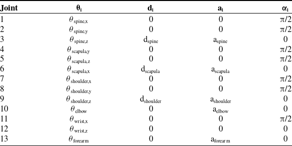


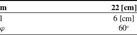


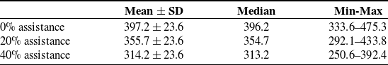
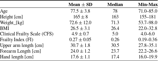

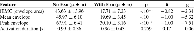

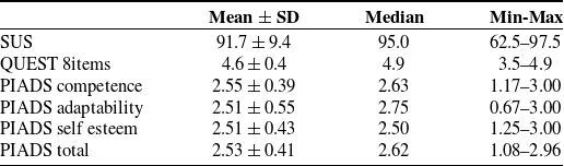

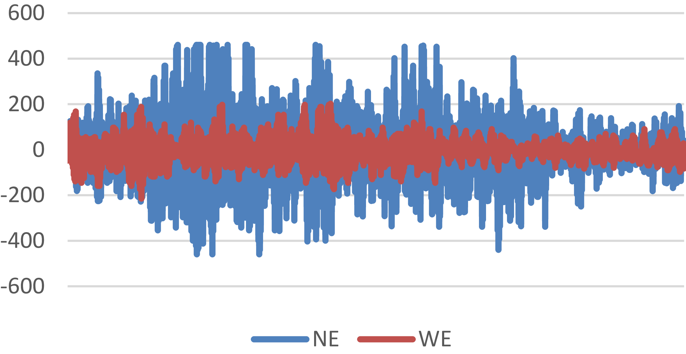
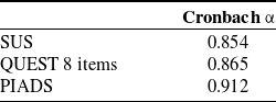

 Open access