


1. Introduction
Designing things is a deeply rooted human activity, probably as old as mankind. In ancient times, designing was usually directly coupled with making (and trying out) the artefacts.
Beginning in the Renaissance and increasingly so in the era of the Enlightenment, science, and with it the art of designing and making things, became a subject of interest in its own right. A famous and influential document is the Encyclopédie ou Dictionnaire raisonné des sciences, des arts et des métiers (Encyclopaedia or a Universal Dictionary of Sciences, Arts and Crafts), edited and published between 1751 and 1781 by Denis Diderot, Jean-Baptiste le Rond d’Alembert and Louis de Jaucourt (Diderot et al. Reference Diderot, le Rond d’Alembert and de Jaucourt1751–1781). For the first time, the Encyclopédie tried to capture and explain the knowledge of the world in a rational manner – not only about things but also about methods and processes (“arts et métiers”). The structure of the Encyclopédie formed a completely new taxonomy of knowledge which influences the organisation of the sciences until today.
During the 19th century, both sciences and engineering developed rapidly and cross-fertilised each other. For instance, the science of thermodynamics followed the invention of the steam engine as opposed to preceding it. At the same time, designing and making/manufacturing artefacts became two separate issues of engineering. One of the earliest authors writing about machine design was Ferdinand Redtenbacher, who is credited with enhancing design with mathematical methods based on physical principles. His works were, however, confined to particular objects, for example, turbines, ventilators and locomotives (Redtenbacher Reference Redtenbacher1844, Reference Redtenbacher1846, Reference Redtenbacher1855). Franz Reuleaux, a disciple of Redtenbacher, followed. Like scientists in other disciplines during the 19th century, he started with systemising knowledge, again concentrating on particular objects. His early publications dealt with machine parts and kinematics as an important (and at that time still widely unexplored) basis for machinery (Moll & Reuleaux Reference Moll and Reuleaux1854; Reuleaux Reference Reuleaux1861). Today, Reuleaux is seen as the father (of the design) of machine elements and mechanisms, based on scientific principles. Reuleaux knew that design is the core of invention and innovation, and even wrote about this (Reuleaux Reference Reuleaux1884), still remaining descriptive however, and not (yet) prescriptive.
This concept – design guidelines for particular objects, based on physical principles and their mathematical description – prevailed well into the 20th century, enhanced both in breadth (more objects covered) and depth (incorporating increased theoretical as well as experimental knowledge and new methods).
During and shortly after World War II the situation changed: considerations on design(ing) were increasingly decoupled from particular objects, the focus shifting from “what”-questions to “why” and “how” (asking for the more abstract reasoning behind concrete objects). More general methods/methodologies were developed and propagated. Early books came from Hugo Wögerbauer (Reference Wögerbauer1943) and Fritz Kesselring (Reference Kesselring1954). Also, the Bulgarian-born Swiss astronomer Fritz Zwicky, working in the USA, had considerable influence (Zwicky Reference Zwicky1948, later elaborated to Zwicky Reference Zwicky1969).Footnote 1
In the 1950s, Design Research (as we would call the field today) really took off. At first named “Systematic Design” (German: Konstruktionssystematik, after the title of a journal article by G. Biniek, Reference Biniek1953), later “Design Theory and Methodology, DTM” (after the National Science Foundation, NSF, in the USA had launched such a research programme in the 1980s), today it is quite generally christened “Design Science.” The origins lay in Europe, in the beginning mostly in Germany where, in contrast to many other countries and their engineering cultures, designing was a highly recognised activity in its own right. Interestingly, for reasons explained below, the Eastern part of Germany (German Democratic Republic, GDR) – and here not least Ilmenau – was about 10–15 years ahead of West Germany (Federal Republic of Germany, FRG).
In parallel, also British contributions emerged (e.g. Wallace Reference Wallace1952; Gosling Reference Gosling1962; Eder & Gosling Reference Eder and Gosling1965; Gregory Reference Gregory1966), and later, usually on a more general note, the first US publications (e.g. Simon Reference Simon1969). Scandinavia and Switzerland became additional hotspots of Design Science. This development was strongly influenced by Vladimir Hubka who, after USSR tanks had ended the so-called Prague Spring in his home country in 1968, had emigrated from Czechoslovakia at first to Denmark and then to Switzerland. The USA followed sometime later, enhanced by the NSF DTM research programme noted above (Dixon Reference Dixon, Newsome, Spillers and Finger1989; Elmaraghi et al. Reference Elmaraghy, Seering and Ullman1989). Some important books, today standard works in Design Science, emerged from this period (Ullman Reference Ullman1992/2017; Ulrich & Eppinger Reference Ulrich and Eppinger1994/2011), and the topic continues to evolve (Ullman Reference Ullman2013; Campbell et al. Reference Campbell, Hölttä-Otto and Linsey2016; Toh et al. Reference Toh, Cagan, Fu, McAdams, McComb, Seering, Thurston and Wood2022).
In all cases, the motivation of increased activities in the field of Design Research was to address the lack of experienced designers and/or deficits of innovative power in the national economies. In consequence, new concepts of teaching design were always closely connected to the research activities – in opposition to the widespread view that design was an art, confined to the gifted, not teachable and not learnable (Heymann Reference Heymann2005).
2. Design Science in Ilmenau
2.1. The town and the university
Ilmenau is a comparatively small town in the Free State of Thuringia in Germany, situated in the northern foothills of the Thuringia Forest. At present, after the incorporation of several smaller municipalities in its neighbourhood, it has about 37,000 inhabitants. In the past it was known for mining (mainly copper, silver and manganese), however, this became uneconomic already during the 18th century.
Ilmenau is also known for the frequent visits of Johann Wolfgang von Goethe (1749–1832) – the first time in 1776 and the last in 1831, half a year before his death. Goethe is known for his literary work, but he was also what we would call secretary of finance and economy in the Principality of Saxony-Weimar-Eisenach with its capital Weimar, approximately 50 km north-east of Ilmenau, that is, about half a day’s ride on a horse, a little more in a horse-drawn coach in Goethe’s time. His sovereign and friend Carl August of Saxony-Weimar-Eisenach (1757–1828) first sent Goethe to Ilmenau with two tasks: get the mining going again and teach the inhabitants of Ilmenau to pay their taxes properly. Goethe tried to fulfil the first task, which worked for a while, but not in the long run: there was at the time no technical means to cope with water in mines at large depths – the steam engine had not yet come to the region. It is not known whether he was successful with the second task… Later, Goethe often returned to Ilmenau, concentrating there on his interests in geology, biology, chemistry, anatomy and forestry, rather than on his literary interests. Nevertheless, in 1780, on top of the Kickelhahn hill close to Ilmenau, he wrote “Wanderers Nachtlied” (Wanderer’s Nightsong), one of his most famous poems.
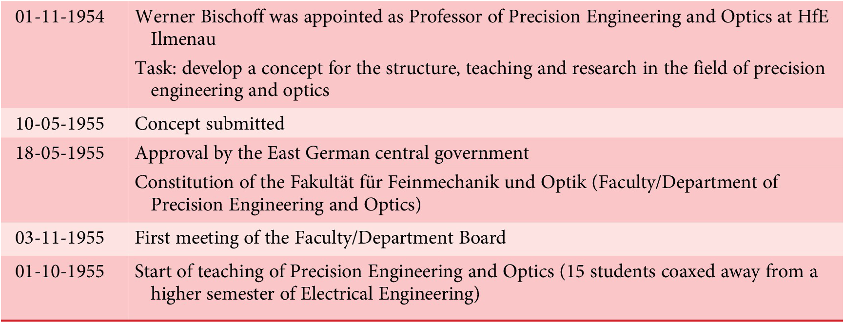
In 1894 a Technical School was founded in Ilmenau (Thüringisches Technikum Ilmenau), the origin of today’s Technische Universität Ilmenau (TU Ilmenau). Table 1 gives a brief overview of its history. A comprehensive history of all chairs and institutes at the Faculty/Department of Mechanical Engineering and its predecessors since World War II is provided in Steinbach & Theska (Reference Steinbach and Theska2015).
Brief history of Technische Universität Ilmenau; special focus on the Faculty/Department of Mechanical Engineering and its predecessors (dates of more general, mostly political events in brackets)
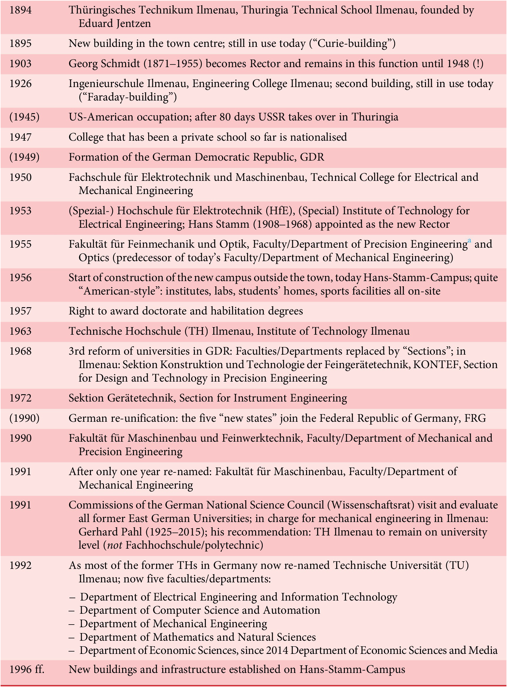
a The original term in German is “Feinmechanik” (“Precision Mechanics”, literal translation: “Fine Mechanics”). An alternative often used – especially in East Germany – was the German term “Feingerätetechnik” that emphasised the engineering aspect better; it can be translated into “Precision Instrument Engineering.” After the German re-unification, it was broadly replaced by the term “Feinwerktechnik” as used in West Germany for which the English translation “Precision Engineering” fits best. In this text, from now on the latter (Feinwerktechnik, Precision Engineering) will be used.
After World War II, Thuringia was at first occupied by US troops, but only for a few weeks (April–June 1945) before being handed over to the Soviets in exchange for West Berlin (after Berlin as a whole had been taken by the Red Army). Therefore, Ilmenau ended up in East Germany, from 1949 the German Democratic Republic, GDR.
In East Germany only one place of higher engineering education was left: Technische Hochschule (Institute of Technology) Dresden – quite insufficient to satisfy the demand for engineers for reconstruction after World War II. Therefore, by decision of the Council of Ministers of the GDR on 6th August 1953, seven Technical Colleges with a good reputation were “upgraded” to Spezialhochschulen (Special Institutes of Technology), each of them with a dedicated focus. If successful, they would be elevated to Technische Hochschule (TH) soon after, later re-named Technische Universität (TU). Along with engineering schools in Cottbus, Dresden, Karl-Marx-Stadt (now again Chemnitz), Leipzig, Leuna-Merseburg and Magdeburg, Ilmenau became one of those Institutes of Technology. From 1953 it was (Spezial-) Hochschule für Elektrotechnik (HfE), (Special) Institute of Technology for Electrical Engineering, soon (1955) with additional focus on Precision Mechanics and Optics.
Today, the TU Ilmenau is one of the medium-sized universities in Germany, having approximately 5,000 to 6,000 students enrolled, taught by around 100 full professors and a scientific staff of about 300 from core funding by the State plus about the same number of researchers funded by external sources (European projects, German National Science Foundation, projects of the Federal Ministry of Research or Economy, industry).
2.2. Origins of the “Ilmenau School of Engineering Design” at the company Carl Zeiss in Jena
Three men brought Design Science to Ilmenau: Werner Bischoff, Friedrich Hansen and Arthur Bock (Figure 1). All three came from the company Carl Zeiss in Jena, situated about 55 km northeast of Ilmenau (linear distance), where they had already developed their initial ideas. Before going into detail, Table 2 provides an overview of their CVs.
Werner Bischoff, Friedrich Hansen, Arthur Bock – the men who brought Design Science to Ilmenau.

Short CVs of Werner Bischoff, Friedrich Hansen and Arthur Bock
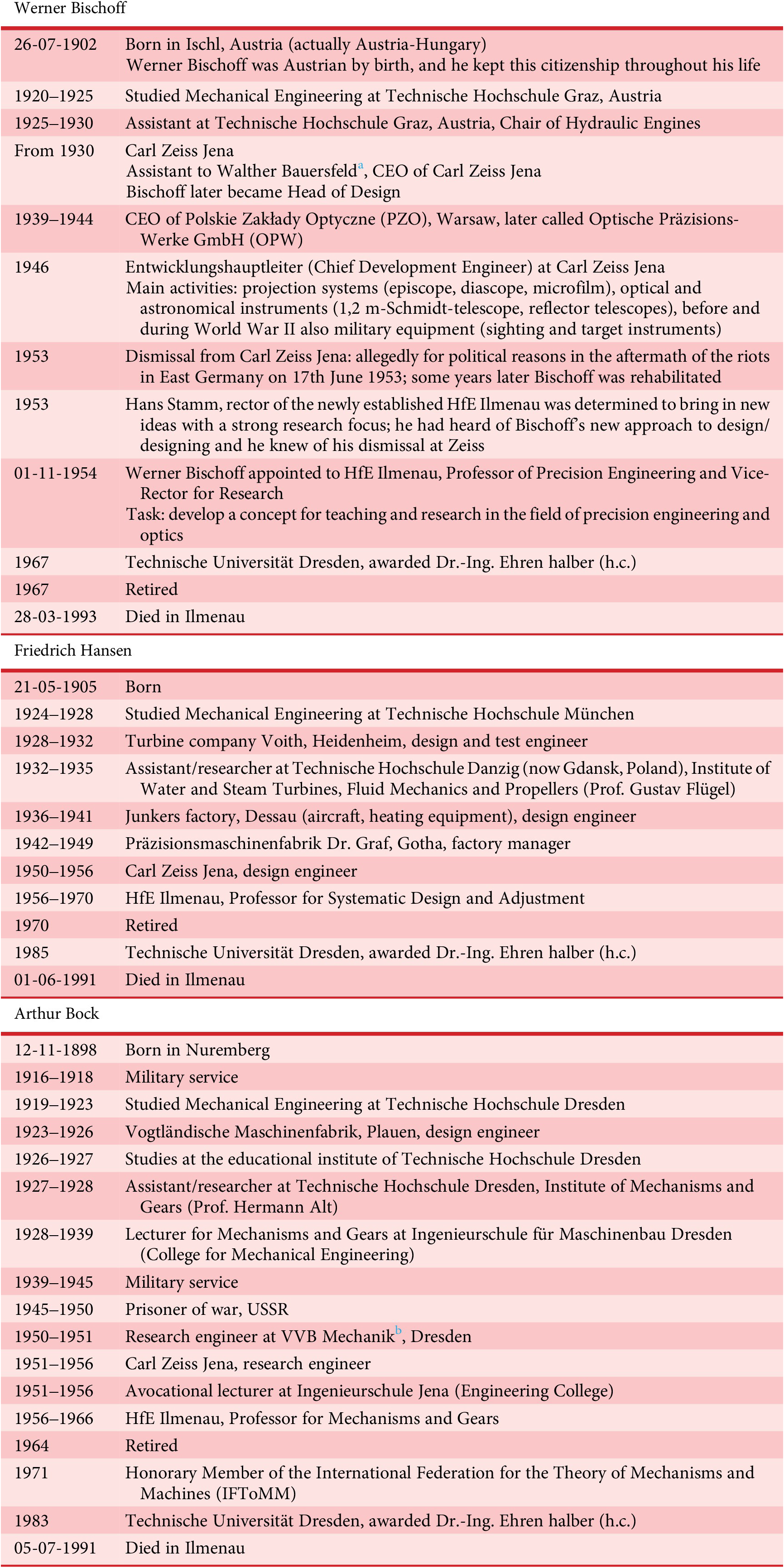
a Walther Bauersfeld (1879–1959): became known as the developer of the original Zeiss planetaria (from 1912). After World War II he was in charge of establishing Zeiss-Opton, the West-German re-founding of Zeiss Jena. Extraordinary Professor at the University of Jena (1927–1945), Honorary Professor at the Technical University of Stuttgart (after 1945). Many awards: 1933 Elliott Cresson Medal of the Franklin Institute; 1941 Werner-von-Siemens-Ring; 1952 Grashof Medal of Verein Deutscher Ingenieure (VDI)/German Association of Engineers; 1953 Great Cross of Merit of the Federal Republic of Germany; 1957 James-Watt-Medal.
b 1948–1951 Mechanik – Vereinigung volkseigener Betriebe (VVB) der Photo-, Kino- und Büromaschinen-Industrie (Association of the People’s Enterprises in the field of photography, cinema and business machines). 1951–1953 Mechanik – VVB der feinmechanischen Industrie (Association of the People’s Enterprises in the field of precision mechanics). “VVBs” were the predecessors of “VEBs” (Volkseigene Betriebe, People’s Owned Enterprises).
Before and during World War II, the Zeiss company, founded in 1846 by Carl Zeiss (1816–1888) in Jena, was an important supplier of precision-mechanical and optical military equipment. In consequence, it was a preferred target of allied air raids and was severely damaged. During the brief US occupation of Thuringia after the war, the Americans requisitioned Zeiss patents, drawings and machinery (worth 15.7 million Reichsmark, about 3.5 million dollars), and also 122 experts from Zeiss and the associated glass company Schott, summing up to around 500 people including their families (Mühlfriedel & Hellmuth Reference Mühlfriedel and Hellmuth2004). They were brought to Heidenheim-upon-Brenz in the American zone (today in the State of Baden-Württemberg). One year later, in nearby Oberkochen, the “Western Zeiss company” was founded, called “Opton Optische Werke” (Opton Optical Works), later re-named “Zeiss-Opton”. Oberkochen is today still the headquarters of the (now re-united) Zeiss company.
After the Soviets came to Jena, what was left at the Zeiss company’s original site was taken to the USSR (≈90% of the remains), together with most of the remaining experts (nearly 300 persons). They were sent to Russian optical factories for 5 to 10 years in order to transfer their knowledge.
When the reconstruction of economic activities started again in all zones of occupied Germany, virtually nothing was left at Zeiss Jena: no drawings, no machines, no engineers, no technicians, only a limited number of skilled workers. Werner Bischoff was appointed Entwicklungshauptleiter (Chief Development Engineer) in 1946 with the challenging task of developing products to get the company running again. He set up a training programme for inexperienced designers comprising:
-
• Analytical training: “Why does a design look like it does?”
-
• Examples of good (partial) solutions, design catalogues
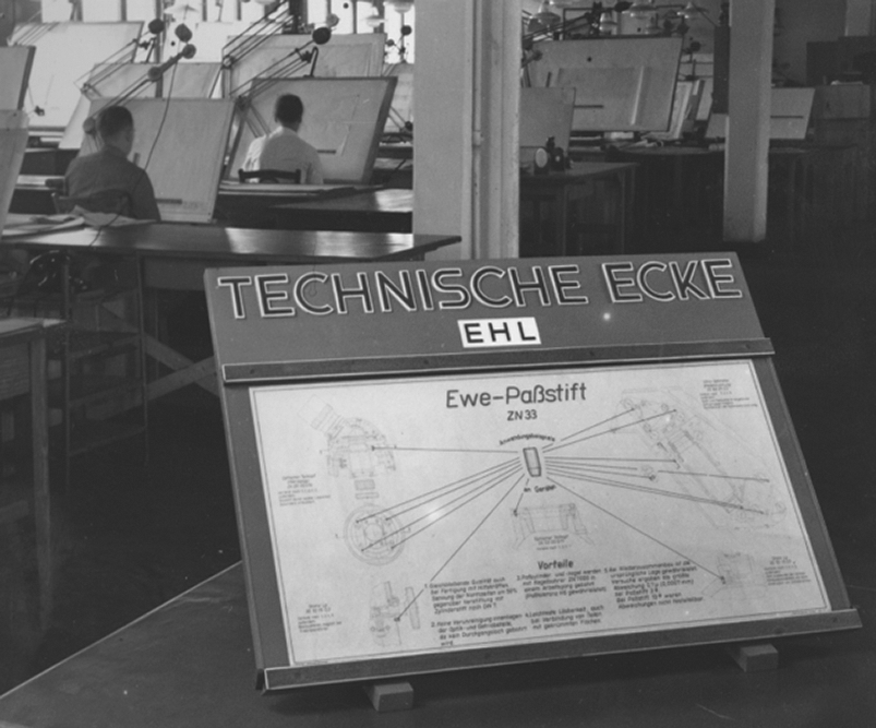
A famous part of this programme was the concept of “Technische Ecke” (Technical Corner) at the Entwicklungshauptleitung (EHL, Main Development Office) of Zeiss Jena in 1951, where – for a multitude of products and components – answers to these questions were presented to the designers (Figure 2).
Example of a “Technische Ecke” (Technical Corner) at the company Carl Zeiss Jena.
In the process, now well-known terms of Design Science evolved:
-
• What are the principles behind GestaltFootnote 2?
-
• In what ways and how are functions served by principles and Gestalt?
Collaborators of Werner Bischoff at the Zeiss company, from 1950 and 1951 respectively, were Friedrich Hansen and Arthur Bock, who would later both follow Werner Bischoff to HfE Ilmenau.
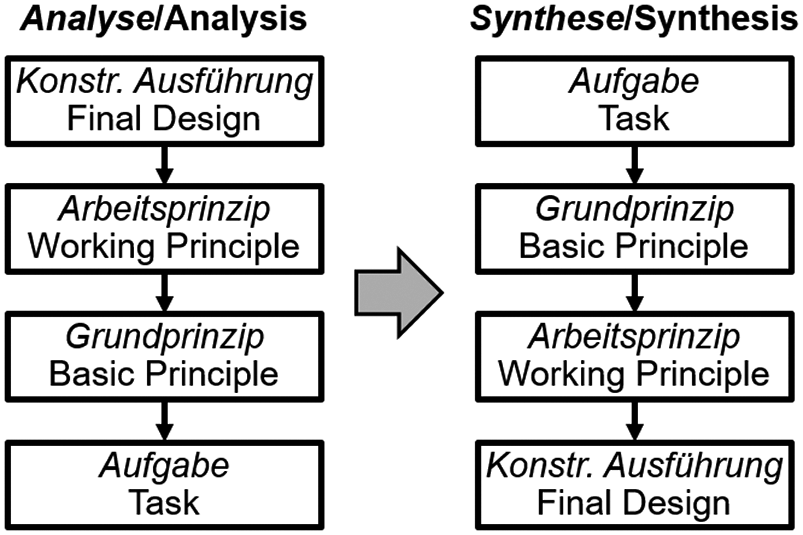
In a next step, Bischoff, Hansen and Bock turned the mainly analytical approach upside down and made it a guide for systematic design (synthesis) (Figure 3).
From analysis to synthesis.
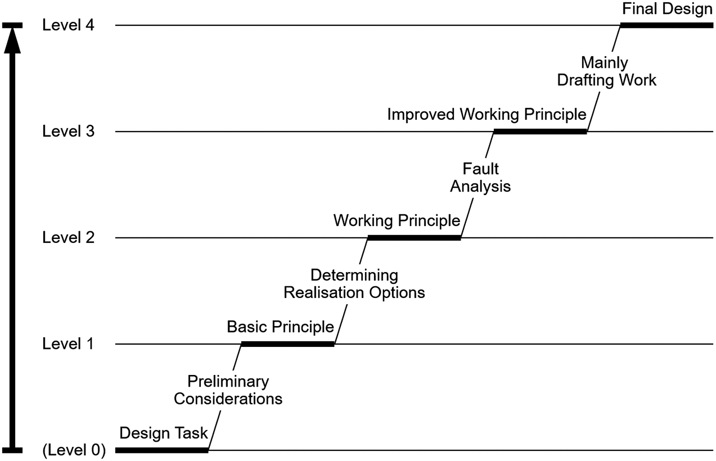
A first publication of just 72 pages – written and published during the authors’ engagement with the Zeiss company in Jena – was released in 1953 (Bischoff & Hansen Reference Bischoff and Hansen1953), marked as “elaborated by the design-scientific collective at Carl Zeiss Jena”, but open to everybody. An even shorter version (40 pages) for practitioners followed soon after (Hansen Reference Hansen1955); this used for the first time the term “Konstruktionssystematik” (Systematic Design), coined by Biniek (Reference Biniek1953). In this publication, a first concept of the steps of a systematic design process was shown, Figure 4, and elaborated. It is interesting to note that the scheme contains a dedicated working step on fault analysis that somehow seems to have been lost.
Development steps of the Systematic Design (Hansen Reference Hansen1955); edited and translated into English by the authors. There is a number of variations of this 4-step scheme (by Bischoff, Hansen, and others); however, this is its earliest form (1955).
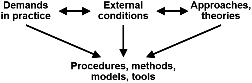
It should be noted that Systematic Design was developed in and for engineering practice in the first place, coming to academia only later. The “trick” was to take up current demands in practice (in this case: the need to design enhanced and new products), respect boundary conditions at the respective time (lack of experienced design engineers and/or of available technical means), look for new approaches and methods that might be helpful (systematic analysis, morphology), and from there come up with models and tools that can solve the practical problem – pictured in hindsight in Figure 5. This means that any change in demand, external conditions or portfolio of approaches/theories can inspire the development of models, methods and tools. In a way, this can be seen as a guideline of Ilmenau’s research in Design Science until today: proposing modified or new models and tools for design and trying them out.
Influences on developing new procedures, methods, models and tools for design.
2.3. Developments 1953–1973
2.3.1. Werner Bischoff comes to Ilmenau
On 17th June 1953 and for some days afterwards, the GDR was shaken by workers’ protests, strikes and riots. Their cause was an increase in work quotas without compensation in wages. The centre was East Berlin, but a number of other (mostly industrial) cities in the GDR joined in, among them Jena. The protests quickly turned to more political issues: demanding free elections, the release of political prisoners, even resignation of the socialist government and immediate re-unification of Germany. In the end, the riots were violently suppressed by Soviet tanks (with at least 55 fatalities), mass detentions, and in the long run even increased political surveillance and suppression (by the “Stasi” – Staatssicherheit, secret police, that massively gained influence after the protests).
Werner Bischoff, at that time Chief Development Engineer at Carl Zeiss Jena, was suspected of being involved in the riots in Jena and at Zeiss in particular, and on 18th June 1953 he was dismissed from his post. Some years later it became clear that this was a false accusation; Bischoff was fully rehabilitated and Zeiss even had to pay his lost salary. However, the damage was done.
The authors have some evidence that the real reason behind Bischoff’s dismissal was to bring in Herbert Kortum (1907–1979) as his successor in the position of Chief Development Engineer at Carl Zeiss Jena. Kortum had just come back from work in the optical industry of the USSR, and he brought ideas for computers that looked very attractive to Zeiss. He later built the GDR’s first digital computer (1955, OPREMA – OPtische REchenMAschine, optical calculator), and in 1960 was appointed extraordinary professor in Ilmenau.
Anyway, Werner Bischoff had lost his job. However, he was almost immediately approached by Hans Stamm (1908–1968), rector of the just newly established HfE Ilmenau, with an offer of a new job. Stamm was interested in bringing new ideas into HfE and in establishing a strong research profile. He was aware of Bischoff’s new approach to design/designing, and at the same time, he regarded precision engineering and optics as an extremely useful extension of HfE’s initial assignment in electrical engineering.
The deal was done: on 1st November 1954 Werner Bischoff was appointed Professor of Precision Engineering and a little later Vice-Rector for Research at HfE Ilmenau. Besides building up his own research group, he got the task of developing an overall concept for teaching and research in the field of Precision Engineering and Optics.
For our time, in which administrative processes seem endless, Werner Bischoff was extremely quick in planning and realising not only a completely new course of studies and future research areas but also a completely new Faculty/Department of Precision Engineering and Optics, Table 3, which became the core of today’s Faculty/Department of Mechanical Engineering (see Table 1).
Timetable of establishing Precision Engineering and Optics at the Hochschule für Elektrotechnik (HfE) Ilmenau (Institute of Technology for Electrical Engineering Ilmenau) 1954–1955
Stamm’s teaching and research concept and its elaboration by Bischoff with its focus on precision engineering and optics continue to influence Ilmenau’s research in the field of Design Science today: the main focus is on precision measuring and positioning instruments, including optics, and related manufacturing machines. This is quite different from many other places active in Design Science where power transmissions, heavy machinery or automotive engineering are in the foreground. Precision measuring and positioning are of particular importance today as it addresses solutions for microelectronics production. No wonder that the Carl Zeiss company, the producer of such equipment, is still an important cooperation partner of TU Ilmenau.
2.3.2. Friedrich Hansen and Arthur Bock join Ilmenau
In order to realise the teaching and research concept as outlined in the previous section, Werner Bischoff succeeded in recruiting his main collaborators at Zeiss, Friedrich Hansen and Arthur Bock, to professorships at HfE (both from 1st September 1956):
-
• Werner Bischoff remained as Professor of Precision Engineering. The Chair still exists at TU Ilmenau today (Chair of Feinwerktechnik/Precision Engineering): after an interim leadership by Friedrich Hansen, Manfred Schilling (1934–2023) took over, at first as a lecturer, then after his habilitation from 1984 as professor; since 2001 the Chair has been led by René Theska.
-
• Friedrich Hansen became a Professor for Systematic Design and Adjustment. This is clearly the first professorship in Design Science in Germany, maybe in the world. The first comparable professorship in West Germany, Wolf G. Rodenacker at Technische Hochschule München, only followed on 1st April 1965. Hansen’s Chair still exists today, between 1973 and 2020 being called “Konstruktionstechnik/Engineering Design”, and since 2021 “Produkt- und Systementwicklung/Product and Systems Engineering”: Between 1973 and 2006 the leader was Günter Höhne, at first as a lecturer, afterwards (1985) appointed full professor; Christian Weber became his successor between 2007 and 2020; since 2021 the Chair is led by Stephan Husung.
-
• Arthur Bock was appointed Professor for Mechanisms and Gears. After Arthur Bock had retired (1964), Gerhard Bögelsack (1932–2011) took over, at first as a lecturer, then from 1968 as full professor. When in 1988 Gerhard Bögelsack had to retire early because of health reasons, Gerhard Christen (1938–2022) became his successor and remained in this position until his retirement in 2003. After an interim period under the leadership of lecturer Henning Pfefferkorn, the Chair has been led since 2008 by Lena Zentner; in this time it has moved a little closer to Engineering Mechanics and was called “Nachgiebige Systeme/Compliant Systems”. It has meanwhile been merged with the Chair of Technical Mechanics and is now called “Mechanics of Compliant Systems.”
To round off engineering design at a German university, research and teaching in the area of machine elements is also required:
-
• At first, machine elements (or design elements, as they were called in Ilmenau at the beginning) were taught by a lecturer (Waldemar Euchler). Only after the 1968 university reform in the German Democratic Republic by which Faculties/Departments were replaced by “Sections”, Design Elements (Konstruktionselemente) became a professorship (Karl-Fried Hager). After the unexpected death of Prof. Hager (1978), a longer interim period followed before Hans-Jürgen Schorcht (1940–2023) took over research and teaching of the subject in 1985. Today, his successor Ulf Kletzin is in charge of the Chair of Machine Elements, successfully continuing the research work in the area of designing, calculating, testing and manufacturing of springs (metallic as well as fibre-reinforced plastic materials) for which Ilmenau is known.
In 2008, the Chairs of Precision Engineering, of Engineering Design, and of Machine Elements (re-) founded the Institut für Maschinen- und Gerätekonstruktion (IMGK) in order to coordinate research and teaching activities as well as resources in the field of design and precision engineering.
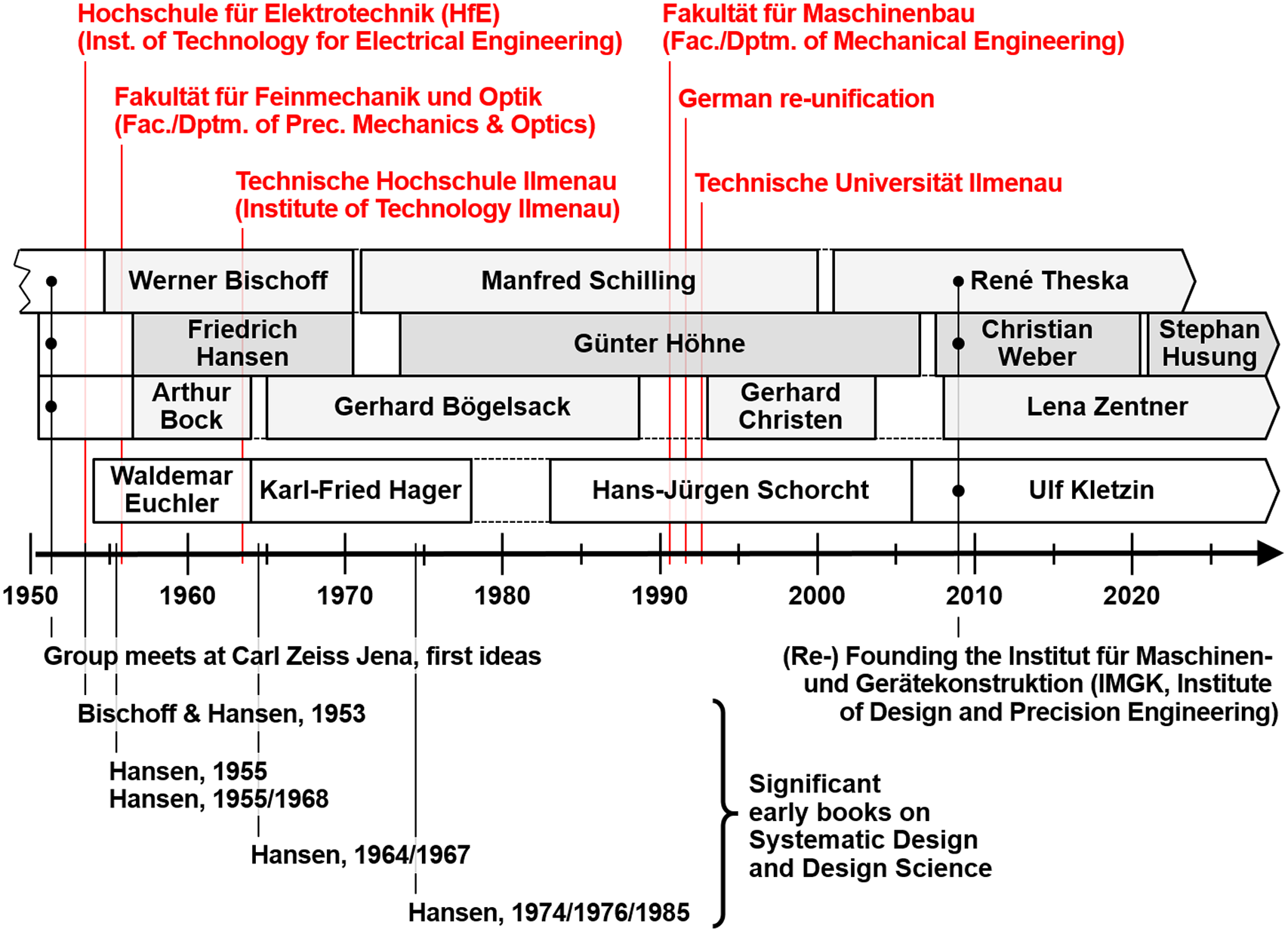
Figure 6 shows the timeline of research/researchers in Design Science at HfE, later TH/TU Ilmenau. Special points of development in university and national politics are also displayed in this scheme (upper part), as well as significant early book publicationsFootnote 3 (lower part).
Timeline of research/researchers in Design Science in Ilmenau.
2.3.3. The principles of teaching engineering design
Werner Bischoff, Friedrich Hansen and Arthur Bock defined a guideline for teaching design within studies of mechanical engineering. It has been systematically developed over the years, the current version is shown in Table 4.
Guideline for teaching engineering design in Ilmenau (current edition)
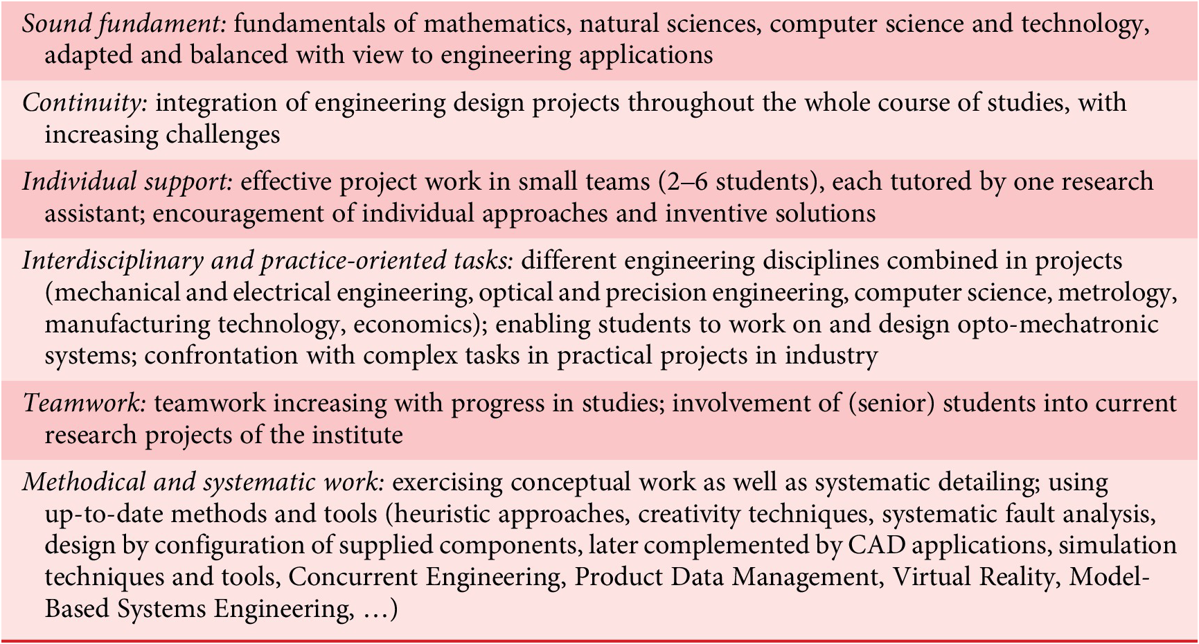
Even if some of the points are compromised by restrictions posed by the so-called Bologna process (e.g. preventing design courses throughout all semesters for all students because of new time constraints, requiring enlarged student teams due to capacity constraints), this guideline is still followed as closely as possible in Ilmenau.
2.3.4. Research 1953–1973
Systematic Design and Design Science
After Friedrich Hansen and Arthur Bock had joined Werner Bischoff at HfE, scientific publications in the field of Systematic Design, later broadened to Design Science, mainly came from Hansen while Bischoff and Bock concentrated on its deepening and application in their respective areas (precision engineering, gears and mechanisms, respectively).
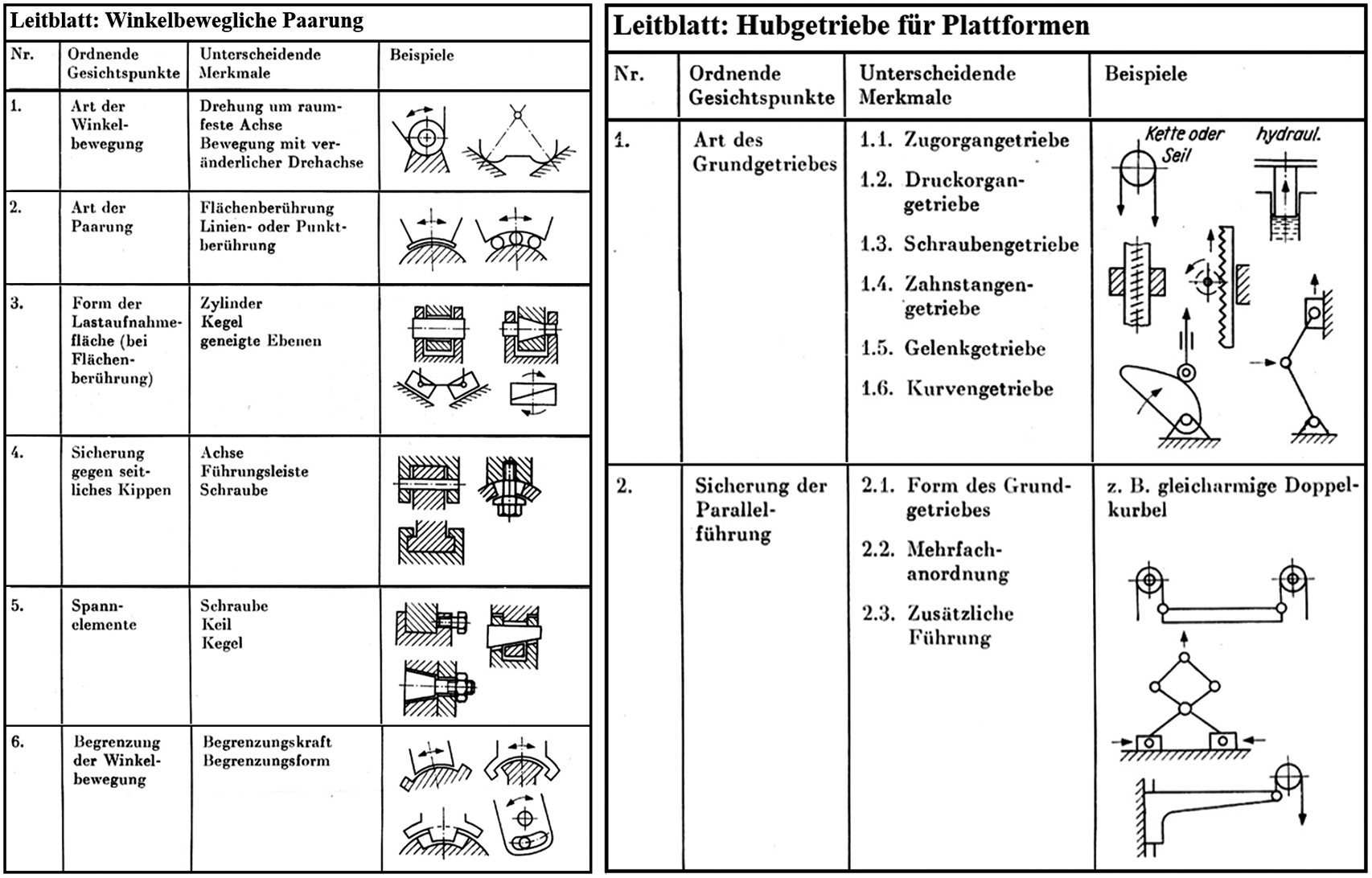
As a follow-up to the very early publications by Bischoff and Hansen on Systematic Design, written while they were still at Zeiss in Jena, Hansen brought out a more elaborated version that also contained design catalogues for realising different functions (Figure 7; Hansen Reference Hansen1955/1968). The book was translated into Russian and Hungarian languages, and its 3rd edition (1968) was even published in West Germany. It can be seen as an early standard work on Design Science.
Leitblätter (guidesheets) as design catalogues, two examples: left – pairings allowing angular movements; right – lifting gear drives for platforms, taken from Hansen (Reference Hansen1955/1968).
Another significant work of Hansen dealt with adjustment techniques of complex systems (Hansen Reference Hansen1964/1967). This book was even translated into English (Hansen Reference Hansen1970). It was based on Hansen’s project work on adjusting Zeiss planetaria during installation: with his methods, the time required for adjustment was cut from several weeks to about 2 days. The main message of the method was to keep (adjustment) parameters as independent as possible.
In 1974 Hansen published a more theoretical book. For the first time, it used the term “Design Science” (Konstruktionswissenschaft) in its title (Hansen Reference Hansen1974/1976/1985). All editions of this book were released in parallel by an East and a West German publishing house. The book contained very comprehensive considerations on products and processes and their relations, also introducing the “system” concept:
“A ‘system’ is generally defined as a clearly delimited part of reality which
-
• has relations to its environment (U),
-
• has a structure (S) and
-
• has a function (F).
There is a meaningful relation between these three system properties. Always the function is determined by the structure and depending on the environment.”
The properties of a system (vector P) were formally expressed by:
P = {U, F, S}.
The core issues for engineering design were expressed by two basic relations between structures (S) and functions (F) (Figure 8):
Relations between functions and structures (Hansen Reference Hansen1974/1976/1985); translated into English by the authors.

Analysis: S → F,
Synthesis: F → S.
The authors of this article think that these considerations, as well as Hansen’ work on adjustment with its emphasis on the independence of parameters, may have been an input for Nam P. Suh when developing his Axiomatic Design theory (Suh Reference Suh1990, Reference Suh2001).
The concept – via Suh’s interpretation and extensions – was also taken up by Christian Weber who brought his theory on Characteristics-Properties Modelling and Property-Based Development (CPM/PDD) so to say “back to Ilmenau” when he came there in 2007 (see details in Section 2.5).
Cooperation with Johannes Müller, Systematic Heuristic
In the early 1960s Johannes Müller (1921–2008), a young a philosopher working at the Technische Hochschule Karl-Marx-Stadt (today again Chemnitz), started studying problem-solving processes of scientists and engineers. From there, he developed the concept (Müller called it a “program”) of the so-called Systematic Heuristic as a means to enhance this type of work.
The Systematic Heuristic is an explanation and technology of intellectual work. Its focus on science and engineering comes from the fact that Müller refused to extend it to social problems (to what we would now call “social engineering”) because he wanted to avoid ideological implications that would have been imminent in the socialistic state of the GDR. As the name “Müller” is quite common in Germany, Müller’s research topic earned him the nickname “Heuristik-Müller” as a distinction.
The Systematic Heuristic consisted of a matrix with tasks and activities of engineering problem-solving (in the terminology of Systematic Heuristic: a “program library”) plus procedural plans of proven methods (“programs”) for each of the activities (Müller Reference Müller1970). It was planned to develop computer tools to support all these activities/programs, but they were never realised. Still, an extended version of the matrix listing these computer tools was published later (Müller Reference Müller1990).
Systematic Design fitted well into Müller’s concept of Systematic Heuristic. Therefore, it is no surprise that some projects in close cooperation took place, including design researchers in Ilmenau, but also in other places.
An important form of cooperation was sending young doctoral candidates working in the field of Design Science to industry for some time (before completing the doctorate), or placing them into R&D in industry (after the doctorate) as so-called methodical consultants (German: methodische Berater). Their task was to advise on and implement the procedures of Systematic Heuristic and/or Systematic Design in industry. One example is the first author of this article, Günter Höhne, who went to the Robotron company in Karl-Marx-Stadt in order to advise on and introduce task clarification, development of solutions and their variants, and evaluation. The methodical consultants were asked to report their experiences to Johannes Müller, and he used these reports – basically case studies – to evaluate whether his concept had been successful or not and to find ideas for improvement.
From 1969 Systematic Heuristic and with it Systematic Design became a big issue in the GDR. It was recognised as a new scientific approach “made in the GDR”, a new and efficient teaching and training concept for engineers, and, above all, a means to outperform “the West” by designing more efficiently and producing better designs in industry.
By the direct intervention of Walter Ulbricht, at that time First Secretary of the monopolist Socialist Unity Party of Germany (in German: Sozialistische Einheitspartei Deutschlands, SED) and Chairman of the State Council of the GDR, thus “strong man” in East Germany, it was decided to transfer Müller’s work group from TH Karl-Marx-Stadt to East Berlin. There it was enlarged and became a department in its own right (Department of Systematic Heuristic) within the newly founded national “Akademie der marxistisch-leninistischen Organisationswissenschaft” (AMLO, Academy of the Marxist-Leninist Organisation Science).
However, for ideological reasons the next “strong man” in the East German government, Erich Honecker (who had kicked his predecessor Walter Ulbricht out of office in 1971) soon reversed all this: AMLO and with it the Department of Systematic Heuristic were dissolved during 1972/1973. Müller and his group of researchers continued their work under the umbrella of the “Zentralinstitut für Kybernetik und Informationsprozesse” (ZKI, Central Institute of Cybernetics and Information Processing), itself part of the Academy of Sciences of the GDR. The focus shifted to investigating work methods in engineering in general, including aspects of computer support. In 1990 Müller gave a résumé of his findings in his much-respected work on work methods in technical sciences (Müller Reference Müller1990).
In his later years, Müller engaged increasingly (and quite self-critically) in the investigation of the acceptance or non-acceptance of methodologies (like Systematic Heuristic) and methods (Müller Reference Müller and Pahl1994). His conclusion: unknowingly, and in an intuitive manner, humans try to work using existing knowledge and existing experiences as long as possible (“normal mode”).Footnote 4 By doing this, the individual’s portfolio of knowledge and experiences is continuously extended. Only if a human’s competencies do not suffice to solve the current problem (and if he or she recognises this!) and/or if a new working style is decreed “from above”, is a transition to systematic, deductive procedures considered (“rational mode”). In other words: systematic problem-solving is avoided as long as possible because it causes increased stress and requires effort; and even if adopted in the past, systematic procedures are set aside again as soon as the external pressure is released.
These are extremely interesting questions that remain still unsolved in Design Science (see e.g. Birkhofer Reference Birkhofer2004; Wallace Reference Wallace and Birkhofer2011).
Cooperation with industry
From the early days of Design Science in Ilmenau, industrial cooperation has played a major role – in both directions: development and transfer of new models, methods and tools for/into industry, but also taking up new demands and current external conditions in industry (see Figure 5). Besides numerous bilateral projects for and in (usually small and medium-sized) companies, working with the company Carl Zeiss in Jena has been particularly significant.
In the 1960s a large industrial research project was founded in several branches of industry within the GDR: “Automatisierung der Technischen Vorbereitung der Produktion” (AUTEVO, Automation of the Technical Preparation of Production). Responsible for the part on precision engineering and optics was Dr. Klaus-Dieter Gattnar, at that time chief designer at Zeiss.Footnote 5
As a part of the AUTEVO programme, from 1965 until 1972 a large project between the Zeiss company and TH Ilmenau was granted under the leadership of Friedrich Hansen: “Maschinelle Simulation konstruktiver Tätigkeiten” (MAKON, Automated Simulation of Design Activities). It consisted of members of several research groups in Ilmenau. The goal was to investigate enhanced computer support in design (CAx). The main focus lay on the early phases of design, and a close cooperation was established with Johannes Müller’s group at TH Karl-Marx-Stadt, see previous sub-section.
The most visible result of the MAKON project was a joint dissertation (doctoral thesis) supervised by Friedrich Hansen: six authors (Fritz Anschütz, Manfred Fritsch, Günter Höhne, Peter Langbein, Helmut Mehlberg and Viktor Otte) worked on different issues of the design process (Anschütz et al. Reference Anschütz, Fritsch, Höhne, Langbein, Mehlberg and Otte1969a,Reference Anschütz, Fritsch, Höhne, Langbein, Mehlberg and Otte b,Reference Anschütz, Fritsch, Höhne, Langbein, Mehlberg and Otte c,Reference Anschütz, Fritsch, Höhne, Langbein, Mehlberg and Otte d,Reference Anschütz, Fritsch, Höhne, Langbein, Mehlberg and Otte e,Reference Anschütz, Fritsch, Höhne, Langbein, Mehlberg and Otte f,Reference Anschütz, Fritsch, Höhne, Langbein, Mehlberg and Otte g,Reference Anschütz, Fritsch, Höhne, Langbein, Mehlberg and Otte h). Figure 9 shows the group in front of the institute building at TH Ilmenau.
The interdisciplinary MAKON research group at Technische Hochschule Ilmenau. Left to right: Fritz Anschütz, Helmut Mehlberg, Peter Langbein, Viktor Otte, Friedrich Hansen, Manfred Fritsch, Günter Höhne. Günter Frank, first group leader, is missing on this photograph.

International Scientific Colloquium
As early as 1956, almost exactly 2 years after he had come to Ilmenau and 1 year after the new Faculty/Department of Precision Engineering and Optics had been founded, Werner Bischoff started a series of conferences called “Internationales Wissenschaftliches Kolloquium” (IWK) or “International Scientific Colloquium” (ISC). From the beginning and maintained until today the IWK/ISC has had the following aims and elements:
-
• Interdisciplinary and international exchange
-
• A platform for researchers from Ilmenau to put up their work for discussion
-
• Ample space to present and discuss new ideas
-
• Connection of science and industry
-
• Also time for “something else” (technical and cultural visits, a concert, dinner)
The 1950s and early 1960s were quite austere times in the whole of Germany and in East Germany in particular. Therefore, it was quite a logistical challenge for the HfE and for the small town of Ilmenau to guarantee the logistics for up to several hundred external participants of the colloquium.
The 1st IWK/ISC took place between 5th and 10th November 1956. It had 70 participants of 10 states from “the East” as well as from “the West”: Austria, Bulgaria, Czechoslovakia, the Federal Republic of Germany, Finland, German Democratic Republic, Poland, Romania, Soviet Union, Switzerland. The programme contained 70 presentations in sections on material technology, material testing, electrical engineering, communication engineering, high-voltage engineering, radiology, physics and applied mathematics, (pure) mathematics, precision engineering and optics, metrology, and finally on standardisation and documentation.
A very significant event was the 12th IWK/ISC 1967 (taking place from 11th to 15th September 1967):
-
• Hansen’s MAKON group (see sub-section further up) presented their results (Hansen, Höhne, Langbein, Fritsch, Otte).
-
• Transition in terminology from Systematic Design to Design Science.
-
• Presentations of Johannes Müller, TH Karl-Marx-Stadt, Klaus-Dieter Gattnar, Carl Zeiss Jena, and Hans-Otto Steinwachs, Technische Hochschule München (1970 named “Technische Universität München”), who later published a quite early textbook on Design Methodology, aimed at teaching and practice (Steinwachs Reference Steinwachs1976).
-
• Presentations of Vladimir Hubka (1924–2006), at that time Prague, ČSSR, and W. Ernst Eder (1930–2017), at that time Swansea, UK. These two now well-known scientists met for the first time during the 12th IWK/ISC 1967, later leading to a fruitful collaboration that lasted over a period of several decades and proved to be extremely influential for Design Science, culminating, for example, in the books (Hubka & Eder Reference Hubka and Eder1992, Reference Hubka and Eder1996).
The conference series IWK/ISC still exists today. It may well be the academic colloquium with the longest unbroken history in existence – in Germany, if not in Europe. In 2014 it had to switch to a three-year cycle (instead of annual until 2012) and was re-named “Ilmenauer Wissenschaftliches Kolloquium” or “Ilmenau Scientific Colloquium,” still using the same acronym (IWK/ISC). In 2020, owing to the COVID-19 pandemic, the colloquium had to be cancelled, with the 60th edition moved to 2023 (from 4th to 8th September 2023). Today, each event attracts more than 300 participants, with 200 presentations in up to 7 parallel streams. Since 2008 the contributions are peer-reviewed, papers are permanently available via the Digital Library Thuringia (www.db-thueringen.de), and since 2014 the language for papers and conference sessions is English.
2.3.5. Reception of the “Ilmenau School of Engineering Design”
This section deals with the reception of the “Ilmenau School of Engineering Design” mainly in Germany – until 1990 consisting of an Eastern and a Western part – and in other German-speaking countries. The main reason for this limitation is that in this sphere procedural models of the design process – like the ones developed in Ilmenau – were quite dominant from the beginning. Also, in the 1950s until the 1970s international crosslinking in Design Science was relatively poor (e.g. to the early British and US American contributions (Wallace Reference Wallace1952; Gosling Reference Gosling1962; Eder & Gosling Reference Eder and Gosling1965; Gregory Reference Gregory1966; Simon Reference Simon1969)), not least because of language problems.
This situation was improved on the initiative of Vladimir Hubka: he was the core person establishing the discussion and working group WDK (Workshop-Design-Konstruktion) in 1978, a forerunner of the Design Society that evolved from it in 2000.Footnote 6 The very small and informal WDK group, at first comprising Vladimir Hubka, Umberto Pighini and Mogens M. Andreasen, founded the bi-annual series of International Conferences on Engineering Design (ICED), the first held in Rome in 1981. ICED still exists today, since 2003 as the flagship conference of the Design Society. Because of the German influence on Design Science in the early years, German remained an official language for ICED conferences and many workshops related to Design Science until the beginning of the 1990s.
Systematic Design had its origins in Ilmenau, East Germany (see Sections 2.3.1–2.3.4), and even became a political issue as part of Johannes Müller’s Systematic Heuristic movement (see Section 2.3.4). In West Germany, it took another 10–15 years before these ideas were adapted and further developed. The authors see three main reasons for this reluctance:
-
• After World War II, West Germany (occupied by the USA, Great Britain and France) had a much easier start in reconstructing its economy than East Germany (occupied by the USSR): from 1948 the removal of industrial facilities as war damage reparations was stopped in the Western zones; West Germany was even supported in the reconstruction of its industry (the so-called Marshall plan, official name “European Recovery Program”, ERP). In contrast, in East Germany, the removal of industrial facilities was continued until 1952. In total, about 670 companies in West Germany were demounted in contrast to 3,400 in (much smaller) East Germany (Grau & Würz Reference Grau and Würz2014).
As a consequence, West Germany experienced its so-called economic miracle (Wirtschaftswunder) in the 1950s, mainly based on pre-war products and technologies. As a result, West Germany had considerably less pressure to start again from zero in the first two decades after World War II.
-
• The majority of universities offering higher engineering education were located in West Germany: Aachen, (West) Berlin, Braunschweig, Darmstadt, Hannover, Karlsruhe, München, and Stuttgart. East Germany only had Dresden left.
As a consequence, there was no real need to increase and reform engineering education in West Germany (and teaching and research in engineering design remained confined to the field of machine elements), whereas in East Germany new educational institutions and methods were dearly necessary. As already explained in Section 2.1, the measure was to “upgrade” seven Technical Colleges to Technical Universities in 1953, among them HfE Ilmenau – thus making room for new ideas like Systematic Design.
-
• Finally, the enthusiastic adoption of Systematic Design (as part of Systematic Heuristic) by East German politics may have caused resentments to adapt these “socialist” approaches in West Germany.
This changed in the 1960s. The first signs of economic decline became apparent in West Germany, and the need for new products and technologies was diagnosed. A very short (24 pages), but nevertheless influential booklet on the “Engineering Design Bottleneck” (Engpass Konstruktion) was published in 1964 by the Verein Deutscher Ingenieure (VDI, [West] German Association of Engineers) (VDI 1964). Some quite hectic activities followed: in a very short period of time several Chairs of Design Science were established at West German universities – 10 or more years after Friedrich Hansen had become Professor for Systematic Design and Adjustment at HfE Ilmenau. Their usual designation was Konstruktíon/Konstruktionstechnik/Konstruktionslehre (Engineering Design):
-
• 1965 TH München (Wolf G. Rodenacker) was the first; half a year later TH Braunschweig (Karlheinz Roth) and TH Darmstadt (Gerhard Pahl)
-
• 1969 TU Berlin (Wolfgang Beitz) and Ruhr-Universität Bochum (Hans Seifert)
-
• 1970 RWTH Aachen (Rudolf Koller)
The authors of this article know from the personal testimony of most of these persons that the results of Werner Bischoff and Friedrich Hansen in Ilmenau (especially Hansen’s book on Systematic Design, Hansen Reference Hansen1955/1968) were an important starting point for their own teaching and research in the area of Design Science.
As was already mentioned (Section 2.3.4) two other now well-known scientists met for the first time in Ilmenau during the 12th IWK/ISC in 1967, thus becoming acquainted with the developments in Ilmenau:
-
• Vladimir Hubka (1924–2006) was in the 1950s and 1960s a designer in the Czechoslovak Socialist Republic (ČSSR) with a professional background in heavy machinery (Škoda machine tools, Plzeň). He was interested in developing and establishing a theoretical background for the “art of designing” (as it was seen in the past) but could not publish his ideas for political reasons.
Things changed when the ČSSR eased its strict Communist regime, eventually leading to the so-called Prague Spring of 1968. In the summer of that year, Hubka was allowed to visit the Technical University of Denmark (DTU) to cooperate with design researchers there, among them the young Mogens M. Andreasen. During Hubka’s stay in Denmark, Warsaw Pact troops invaded his home country; this made him decide to stay in the West. Luckily his family was with him, and Andreasen found a job for him at DTU for a while. Two years later Hubka moved to the Swiss Federal University of Technology, Zurich (Eidgenössische Technische Hochschule Zürich, ETH) where he stayed until the end of his professional life.
Hubka was soon building up a network of researchers and teachers interested in Engineering Design. As already mentioned, in 1978 he founded the WDK group from which eventually the Design Society emerged.
-
• W. Ernst Eder (1930–2017), born in Vienna, Austria, was in the 1960s a lecturer at Swansea University, UK. He later moved on to the University of Calgary, Canada, then to Loughborough University, UK, and was finally appointed Professor at the Royal Military College Canada (RMC) in Kingston, Ontario. He had written earlier articles and books on Engineering Design (Eder & Gosling Reference Eder and Gosling1965) as well as several chapters in Gregory’s well-known book on design methods (Gregory Reference Gregory1966).
Apart from these achievements and his later collaboration with Vladimir Hubka, Eder played a major part in linking the German/central European approaches to Design Science with the Anglo-American and Canadian views.
In the following years, a wealth of books on Design Theory and Methodology was published by the persons named above, at first all in German and many of them released in several editions: (Hubka Reference Hubka1973, Reference Hubka1976; Andreasen Reference Andreasen1980; Rodenacker Reference Rodenacker1970/1991; Hubka & Eder Reference Hubka and Eder1992; Koller Reference Koller1976/1998; Roth Reference Roth1982/1999; Pahl & Beitz Reference Pahl and Beitz1977/2013). All made reference to the results of Bischoff and Hansen in Ilmenau, mainly to Hansen (Reference Hansen1955/1968), later also to Hansen (Reference Hansen1974/1976/1985), before explaining their own findings and extensions.
The early publications of the Ilmenau researchers were only published in German (apart from Hansen’s book on adjustment (Hansen Reference Hansen1970)), as were most of the books of the West German authors named above. Therefore, their international coverage remained limited. Only the book of Pahl and Beitz was translated into English (and into some other languages, among them Chinese), thus becoming one of the best-known publications on Design Theory and Methodology worldwide. The English language translation and editing were performed by Ken Wallace (1944–2018) and Lucienne Blessing (Pahl & Beitz Reference Pahl, Beitz, Wallace and Blessing1983/2006) who both gained deep knowledge of the German contributions to Design Science (Wallace & Blessing Reference Wallace and Blessing2000). An extended version of the book of Hubka and Eder on Design Science (Hubka & Eder Reference Hubka and Eder1992) was also published in English (Hubka & Eder Reference Hubka and Eder1996),
In West Germany, the VDI had for a long time been dedicated to supporting designers in practice by providing guidelines. The issue of design methodology was also taken up quite early: the first outcome was VDI-guideline 2222 (VDI 1977), later developed into VDI-guideline 2221 as a basic framework for design processes (VDI 2221 1986/1993), with an extensively modernised version released quite recently (VDI 2019). The basic framework according to VDI 2221 (1986) was almost immediately translated into EnglishFootnote 7 (VDI 1987), thus becoming – alongside the book of Pahl and Beitz – another important reference for many international research activities to this day. Complementing trends in industrial practice, where products and systems became increasingly “mechatronic,” the VDI released an additional guideline on the development of mechatronic systems (VDI 2004). This was a first and, therefore, much-referenced attempt to come to a broader perspective of engineering design – even if, seen from the Ilmenau perspective, the optical part is missing.
An extremely insightful overview of the development of Design Science – with a focus on East and West Germany – is provided in Heymann (Reference Heymann2005).
As was already mentioned (Section 2.3.4), certain elements of Hansen’s books on Adjustment (Hansen Reference Hansen1964/1967, Reference Hansen1970) and on Design Science (Hansen Reference Hansen1974/1976/1985) may have had an influence on Nam P. Suh’s Axiomatic Design theory, namely the independence axiom (the importance of the independence of adjustment parameters was a main message of Hansen (Reference Hansen1964/1967) and (Reference Hansen1970)) and the relations between design parameters and functional requirements that are similar to the relations between structures and functions according to Hansen (Reference Hansen1974/1976/1985), see Figure 8.
After the so-called Fall of the Wall (1989) and the subsequent German re-unification (1990) Ilmenau’s early contributions to Design Science were officially recognised on a broader scale, for example:
-
• At the 8th International Conference on Engineering Design (ICED ’91) in Zurich a special workshop was organised on “40 Years Ilmenau School of Engineering Design” (Ilmenauer Schule der Konstruktionslehre). TH Ilmenau was represented by Manfred Schilling (1934–2023, head of the Chair of Precision Engineering, successor of Werner Bischoff), Günter Höhne (head of the Chair of Engineering Design, successor of Friedrich Hansen), Hans-Jürgen Schorcht (head of the Chair of Machine Elements), and Horst Sperlich (lecturer at the Chair of Engineering Design). Among the attendees from outside Ilmenau were Vladimir Hubka, W. Ernst Eder, Wolfgang Beitz, Gerhard Pahl, Karlheinz Roth, Klaus Ehrlenspiel (TU München, successor of Wolf G. Rodenacker) and Christian Weber (to become successor of Günter Höhne and second successor of Friedrich Hansen 16 years later).
-
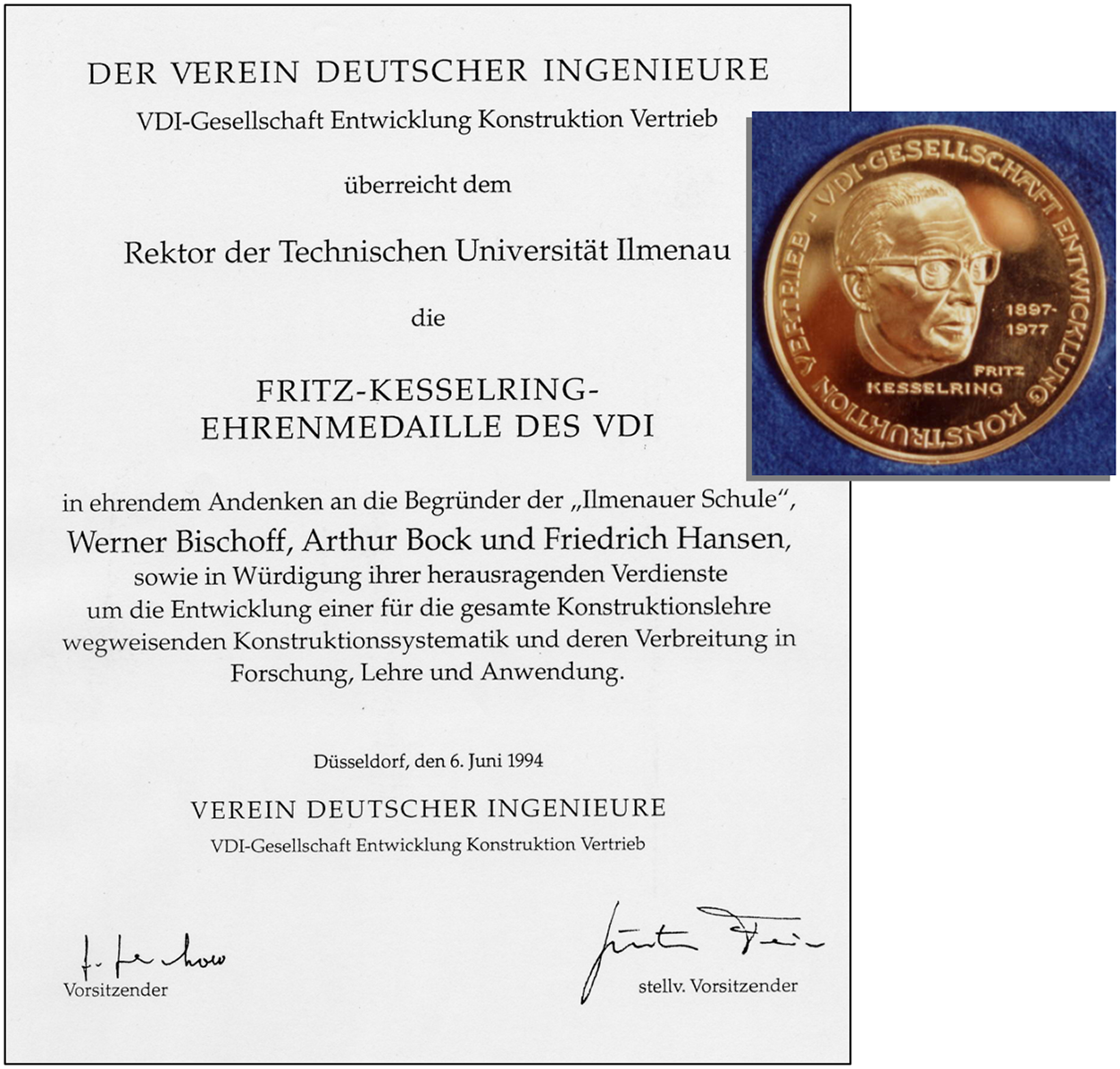
• In 1994 TU Ilmenau was awarded the Fritz Kesselring Medal of Honour by the (now pan-German) VDI (Figure 10). The inscription reads:
In honourable memory of the founders of the ‘Ilmenau School’, Werner Bischoff, Arthur Bock and Friedrich Hansen, and in recognition of outstanding achievements for the development of a Systematic Design that has proven trendsetting for Design Science and its dissemination in research, teaching and application.
Fritz Kesselring Certificate and Medal of Honour awarded to TU Ilmenau “in honourable memory of the founders of the ‘Ilmenau School’, Werner Bischoff, Arthur Bock and Friedrich Hansen”.
2.4. Developments 1973–2006
After Friedrich Hansen had retired (1970), in 1973 Günter Höhne followed, first as lecturer, later (1985) appointed full professor of Engineering Design. Höhne had acquired his doctorate under the supervision of Hansen (Anschütz et al. Reference Anschütz, Fritsch, Höhne, Langbein, Mehlberg and Otte1969a,Reference Anschütz, Fritsch, Höhne, Langbein, Mehlberg and Otte b,Reference Anschütz, Fritsch, Höhne, Langbein, Mehlberg and Otte c,Reference Anschütz, Fritsch, Höhne, Langbein, Mehlberg and Otte d,Reference Anschütz, Fritsch, Höhne, Langbein, Mehlberg and Otte e,Reference Anschütz, Fritsch, Höhne, Langbein, Mehlberg and Otte f,Reference Anschütz, Fritsch, Höhne, Langbein, Mehlberg and Otte g,Reference Anschütz, Fritsch, Höhne, Langbein, Mehlberg and Otte h) and had then gone to industry (Robotron, Karl-Marx-Stadt/Chemnitz). During his industrial affiliation, he had already been invited to teach Engineering Design at TH Ilmenau. He led the Chair at TH Ilmenau, then TU Ilmenau, until 2006 (see Figure 6). His time of office spanned the German re-unification (1990). In the years immediately after the re-unification all professors and other scientific staff with permanent contracts had to re-apply for their own positions, getting them back only after thorough scientific as well as political scrutineering. Thus, Günter Höhne had the very difficult task to bring the Chair of Engineering Design at TH/TU Ilmenau through the turbulences of the early 1990s and to plant it firmly into the national and international scientific community. In addition, he also took on responsibility for the university as a whole in the office of Vice-Rector for Education (1995–1997). In this role, he considerably renovated the teaching concepts of TU Ilmenau, for example by introducing study programmes on Media Science and Technology.
2.4.1. Research 1973–2006
Product development and design process
In research, the Chair of Engineering Design at TH/TU Ilmenau under the leadership of Günter Höhne built onto the foundations laid by Bischoff, Hansen and Bock. (In the first years some projects were still supervised by his retired predecessor Friedrich Hansen.) Extensions and details to the Systematic Design approaches were added, additional methods developed, and findings were brought to industry – also for testing and improving them (see sub-section “Cooperation with industry” in Section 2.3.4). Beginning in the late 1970s, investigating the potential of computer tools in development and design processes as well as developing them came increasingly into focus.
The main application area remained precision engineering where mechatronics has always been an issue (long before the term “mechatronics” was coined by the Japanese Yaskawa Electric Corporation in 1969). In this case, besides mechanical, electric/electronic and software components, optical components were also included. Figure 11 shows this in a scheme of the development and design process for precision engineering and mechatronic products published in Höhne et al. (Reference Höhne, Schilling and Sperlich1983).
Model of the development and design process for precision engineering and mechatronic products; outcome of the MAKON project (Höhne et al. Reference Höhne, Schilling and Sperlich1983); translated into English by the authors.

Research in Design Science – then and now – mostly addresses the often so-called early phases, that is, functional and principle considerations, sometimes summarised under the term “conceptual design” (Andreasen et al. Reference Andreasen, Hansen and Cash2015). This is important for original design (or “New Product Development”, NPD), and it is also understandable because exactly these early phases were almost non-existent in design practice and teaching before Design Science came into focus. However, original design is a rare occurrence in industry, most tasks requiring adaptive or variant design. In consequence, layout and embodiment design (“late phases”) are much more in the foreground; and these issues, including the transition from a technical principle to “Gestalt5”, has been until now rarely addressed and are therefore still poorly understood in Design Science.
A very general approach, containing both theoretical considerations and practical guidelines (for the application area of Precision Engineering), was provided by Horst Sperlich in his dissertation B (habilitation thesis) at TH Ilmenau (Sperlich Reference Sperlich1983). In the view of the authors, it would be well worthwhile to follow up this path, for several reasons: a still open gap in Design Science would be filled, new challenges for layout and embodiment design arising from new technologies could be met, new computer tools based on advanced information technologies may be envisaged, thus moving Design Science closer to design practice.
Fault-tolerant design – today we would call it “Robust Design” – has always been an issue in the Design Science-related work in Ilmenau (see the dedicated step in the scheme as shown in Figure 4). Hansen explained the “method of virtual deviations” for fault analysis in all his books (Hansen Reference Hansen1955, Reference Hansen1955/1968, Reference Hansen1964/1967, Reference Hansen1970, Reference Hansen1974/1976/1985). He also introduced the concepts of so-called invariance and innocenceFootnote 8 as means to fight functional faults (not far away from the independence axiom in Suh’s “Axiomatic Design” theory; Suh Reference Suh1990, Reference Suh2001). More examples are documented in the practice-related guidelines of the KOIN project (see next sub-section, in particular, no. 2, 6, 8, 15, 18 and 19 in Table 5). A publication from the 1973–2006 era is Höhne et al. (Reference Höhne, Brix and Sperlich2005a). Since the 1980s a dedicated course on Fault-Tolerant Design has been led by the Chair of Engineering Design (since 2007 by Senior Engineer Dr. Torsten Brix).
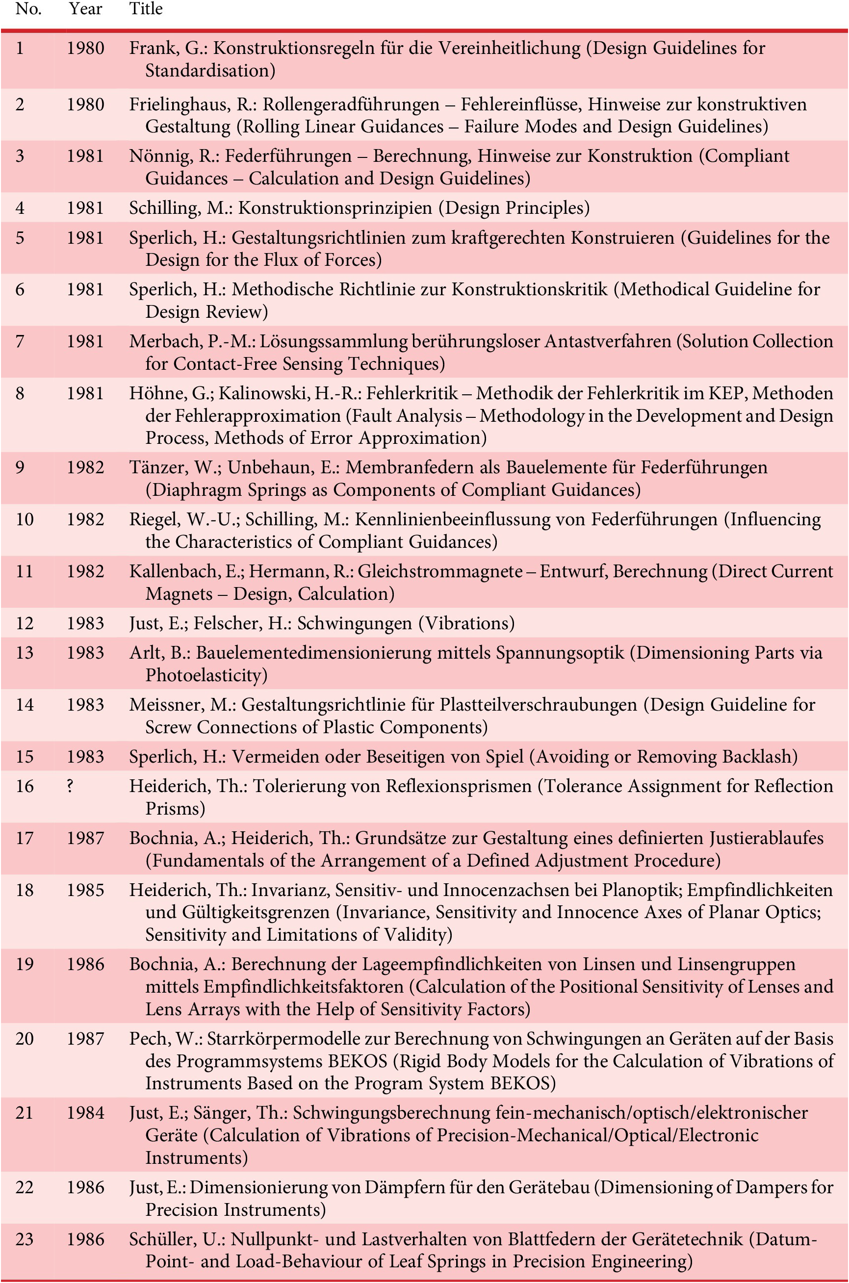
List of the publicly available guidelines of the KOIN project (Konstrukteurinformationen, designer information)
Cooperation with industry
Bringing procedures, methods, models and tools to industry – small and medium-sized enterprises as well as large companies – has always been a major concern of the design scientists in Ilmenau, as a means of knowledge transfer as well as of testing and improving the findings and approaches. Two larger projects, both with and for Carl Zeiss in Jena, will be briefly described.
In the 1970s a large investigation was conducted, asking what types of information are needed by designers when designing and what type of information preparation and storage is appropriate (Frank Reference Frank1975; Preschner Reference Prescher1976; Gundermann & Türpe Reference Gundermann and Türpe1978).
The knowledge gained led to a large project in the late 1970s and early 1980s, called Konstrukteurinformationen (KOIN, designer information). Developed in cooperation with several chairs and research groups at TH Ilmenau (Engineering Design, Precision Engineering, Machine Elements), KOIN was a collection of design guidelines (addressing methods) and catalogues (presenting and explaining solutions) for designers in practice that were later also used for teaching. The application focus was Precision Engineering, including sensors, actuators and optics – that is, usually small dimensions and loads in return for high precision. Most of the KOIN content was later digitised (interlinked HTML files) for teaching.
The design information comprised two parts:
-
• that from research projects (TH Ilmenau): publicly available
-
• internal know-how of Carl Zeiss Jena: not publicly available
Table 5 lists the 23 publicly available KOIN volumes.
The project used conventional media throughout – design guidelines and catalogues documented on paper and microfiche. However, the findings and concepts later went into the development of new kinds of computer-supported information and knowledge repositories (see next sub-section).
A second example of the successful cooperation between the Chair of Engineering Design and Carl Zeiss in Jena is the development of a much improved self-adjusting alignment turning station for centring and aligning round lenses, conducted between 2002 and 2006 (Frank Reference Frank2008). Lenses or lens groups, mounted in their holders, are manipulated in such a way that their optical axis is aligned to the rotating axis of the machine tool. Now the lens holder can be machined so that its spin axis and the optical axis of the lens coincide, at the same time ensuring the required (tight) tolerances and fits of the holder.
Figure 12 shows the Technical Principle (top) and the machine as built and used by Carl Zeiss Jena for their own lens manufacturing (bottom). The machine was not patented in order to keep its secrets inside the company.
Self-adjusting alignment turning station for centring and aligning mounted lenses (Frank Reference Frank2008); top – technical principle, translated into English by the authors; bottom – machine as built and used [Carl Zeiss Jena GmbH].
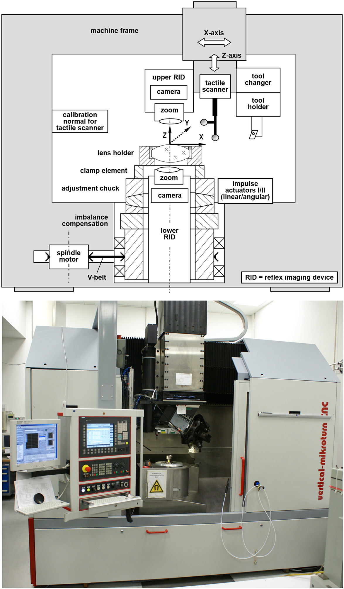
Based on systematic studies of solution alternatives for all functions, the novel features of the machine were:
-
• The use of two reflex imaging devices (RID) to detect the correct alignment of the optical axis of the lenses to the rotating axis of the machine tool
-
• The integration of all elements into the machine: measuring instruments (RIDs, tactile scanner) as well as the tool itself
-
• The use of impulse actuators (“μ-hammers”) to bring the lens/lens group into alignment – outside the mechanical axis of the machine
-
• A new algorithm (“extended calculation of comparison values”) for the treatment of coupled adjustment cycles
The new machine could improve both the alignment accuracy and air gap deviations to ≤ 2 μm; the process time could be cut from 45 to 15 minutes, and change-over times reduced by 80% (Frank Reference Frank2008). It was used for about a decade by Carl Zeiss Jena before being replaced by another new and now also robotised technology (skew-turningFootnote 9).
Focus on computer support
Beginning in the 1970s, the Chair of Engineering Design investigated computer tools to support development and design processes. Before the so-called Fall of the Wall and the subsequent German re-unification this was not an easy task because TH Ilmenau was located in East Germany and the embargo imposed by the so-called CoCom listFootnote 10 prevented the import and use of current Western information technology (or, sometimes, necessitated “unconventional” acquisition methods).
Nevertheless, based on the results of the MAKON project (see sub-section “Cooperation with industry” in Section 2.3.4) and additional preliminary considerations (e.g. Borys Reference Borys1976; Lotter Reference Lotter1978; Chilian Reference Chilian1987; Eick Reference Eick1988; Pech Reference Pech1988) together with other groups at TH Ilmenau, ILKON was devised and partially realised – a comprehensive computer support system for design tasks of precision engineering and mechatronics (Figure 13; Höhne Reference Höhne1990).
ILKON (ILmenauer KONstruktionssystem), a comprehensive computer support system to assist the design of precision engineering and mechatronic products, based on results of the MAKON project (see Figure 11), developed in cooperation with other groups at TH Ilmenau (Höhne Reference Höhne1990); scheme translated into English by the authors.
Other works dealt with the link between design theory and methodology and computer-support (Höhne Reference Höhne1988, Reference Höhne1990) and computer-support specifically for precision engineering (Höhne & Seydel Reference Höhne and Seydel1988; Höhne et al. Reference Höhne, Herrig, Meissner and Simon1989; Höhne & Schorcht Reference Höhne and Schorcht1990).
In the 1990s the use of the so-called feature-technology to enhance the design in precision engineering was investigated (Leibl Reference Leibl1998; Spiller Reference Spiller1998). Originally, the feature-technology was a concept to enrich geometric data (as stored in CAD-models) with semantic information. At first manufacturing information was addressed (Shah et al. Reference Shah, Mäntylä and Nau1994), later also functional and other information was included as well as combinations thereof Weber (Reference Weber1996).
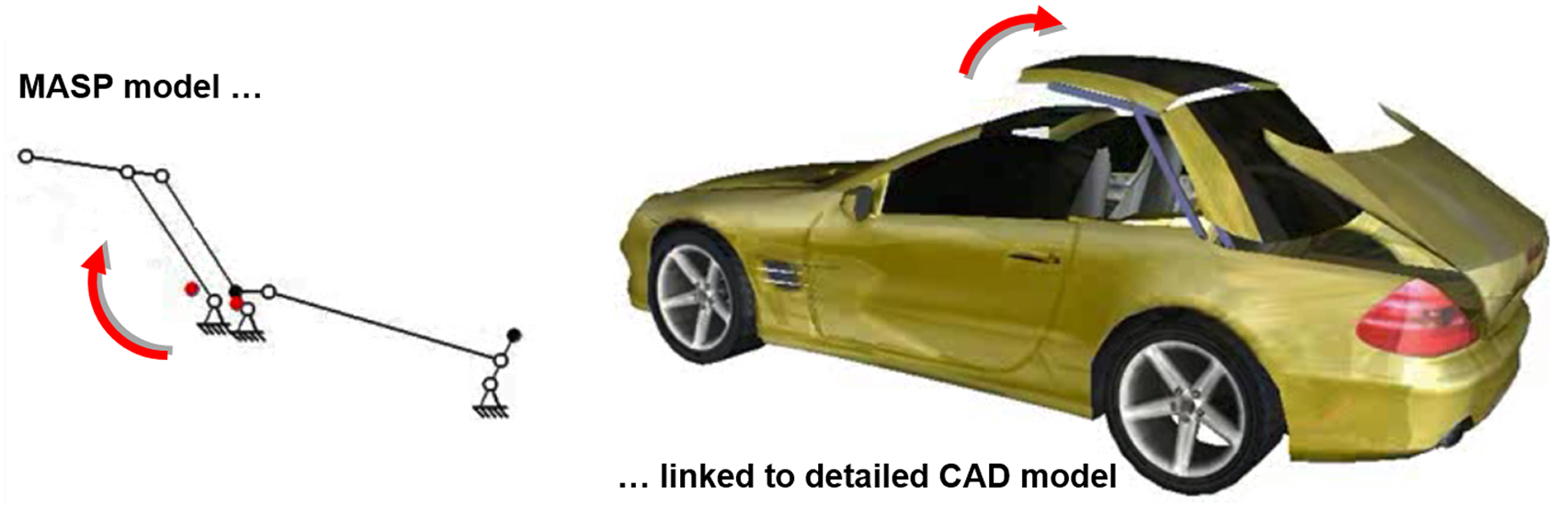
In this context, an important work was published by Brix (Reference Brix2001) who later became (and still is) Senior Engineer at the Chair of Engineering Design (today Chair of Product and Systems Engineering): he developed a constraint-based modelling tool called “Modelling and Analysis of Solution Principles” (MASP) that allows modelling and simulation of solution principles and embodiment designs, including kinematic and simple kinetic analyses. The elements of the principle descriptions, their control and their motions in MASP can also be linked to more detailed geometric representations (e.g. CAD models, additional domain-specific behavioural descriptions; Reeßing Reference Reeßing2016; Figure 14). A basic version of this software is still available as freeware via several internet portals.
Modelling of a mechanism with MASP (Modelling and Analysis of Solution Principles) and link to a fully detailed CAD model (example after Höhne et al. Reference Höhne, Brix, Henkel, Lotter, Lotz and Reeßing2005b).
Digital Mechanism and Gear Library
MASP became the core of a very large project called DMG-Lib (Digital Mechanism and Gear Library), led by Torsten Brix. In the first period (2006–2010), funded by the German National Science Foundation (Deutsche Forschungsgemeinschaft, DFG), three German universities (RWTH Aachen, TU Dresden, TU Ilmenau) worked together to collect and digitise all sorts of information on mechanisms and gears. The idea was to establish a digital knowledge repository both for practice and teaching, at the same time trying out new presentation techniques provided by current media technologies (Brix et al. Reference Brix, Döring and Reeßing2007; Henkel & Kloppenburg Reference Henkel and Kloppenburg2008; Reeßing et al. Reference Reeßing, Brix and Döring2011).
In a second period (2010–2013) the concept was extended to six European partners: the University of the Basque Country in Leioa/Lejona close to Bilbao; Institut Français de Mécanique Avancée (IFMA) in Aubière/France; RWTH Aachen/Germany; TU Ilmenau/Germany; Università degli Studi di Cassino et del Lazio Meridionale/Italy; Universitatea Politehnica Timisoara/Romania. Thus, the DMG-Lib database could be considerably extended (Corves et al. Reference Corves, Brix, Döring and Ceccarelli2011). The title of this project was “ThinkMotion,” funded by the European Union under the Europeana initiative.Footnote 11
The results are openly available at www.dmg-lib.org. At the time of writing, the published content comprises:

Many more sources have been captured but remain still unpublished because of copyright restrictions that are different in different countries. For instance, Germany has one of the most rigid legislations which allows the publication of intellectual property only with written agreement of the author or his or her heirs (often difficult to obtain, e.g. from heirs that may be unknown) or 70 years after the author’s death.
The animations (of digital as well as physical models of mechanisms, many of the latter of historic value themselves) are realised using the MASP software (Figure 15). In some cases – as far as resources allowed – animations are integrated into books and articles, thus providing a completely new concept of information provision.
Step mechanism of the Geneva type (Maltese cross mechanism), excerpt of DMG-Lib (www.dmg-lib.org): drawing [RWTH Aachen], plastic model for teaching [RWTH Aachen], CAD model [Universitatea Politehnica Timisoara], metal model manufactured 1930 [TU Dresden]. In DMG-Lib all models, except the drawing, can be animated, in video as well as interactive forms.

DMG-Lib is one of the largest, if not the largest information repository on mechanisms and gears, with a user interface in six languages (German, English, French, Romanian, Italian, and Spanish) and extensive search functions for books, articles, drawings, models (both digital and physical), particular solutions, descriptions, and persons. Many of its features cannot be shown in a paper, everybody is invited to browse and search him−/herself!
Audio-visual virtual reality in design
In the new millennium, the Chair of Engineering Design started to investigate the application of Virtual and Augmented Reality (VR/AR) techniques to support development and design processes (Schilling Reference Schilling2008). By 2005, a far-reaching concept had been created by Günter Höhne and his team: the combination of visual and acoustic VR. The aim was to enable a simulation of the behaviour of technical products and systems, including their acoustics. With conventional methods, acoustics can only be assessed late in the design process, usually based on physical tests that require prototypes or even the finished product. The new concept aimed at much earlier phases, using simulation and an audio-visual virtual environment for presentation.
After some initial studies with smaller equipment, a quite large Flexible Audio-Visual Stereo Projection Device (FASP) was planned, installed and put into operation in February 2007 for use primarily by the Chair of Engineering Design but also several other institutes of TU Ilmenau (Figure 16).
Flexible Audio-Visual Stereo Projection Device (FASP) at TU Ilmenau; visualisation by three stereo projection screens in flexible configurations, auralisation (acoustic presentation) via Wave-Field Synthesis (WFS) produced by speaker panels arranged in a plane roughly at the height of the users’ ears.

The visual presentation used commercially available VR hard- and software (from different vendors). The auralisation (acoustic presentation, also called “acoustic rendering”), however, used an entirely new concept: Wave-Field Synthesis (WFS). Based on theoretical proposals of A.J. (“Guus”) Berkhout of TU Delft in the Netherlands (Berkhout Reference Berkhout1988; Berkhout et al. Reference Berkhout, de Vries and Vogel1993), it was developed as a product by the Fraunhofer Institute of Digital Media Technologies (IDMT) in Ilmenau. IDMT is situated on the campus of TU Ilmenau; and from its foundation in 2000 until 2019 was led by Karlheinz Brandenburg, one of the inventors of the mp3 audio standard (Brandenburg et al. Reference Brandenburg, Brix and Sporer2004).
The working principle of Wave-Field Synthesis is illustrated in Figure 17: Sound sources are simulated by a superposition (Huygens’ principle) of elementary waves, produced by an array of speakers that are individually controlled in their volumes and delays by the WFS software. Thus, a flat (if all speakers are installed in a plane) or even spatial (if a three-dimensional speaker array is installed) wave field is generated in the complete area surrounded by the speaker array. The more speakers, the more exact is the result. Independent of the user’s position, he/she gets a correct acoustic impression; tracking the user (as in stereoscopic visualisation) is not necessary.Footnote 12
Principle of acoustic rendering using wave-field synthesis; two (external) sound sources as an example; source: (Husung Reference Husung2012), edited and translated into English by the authors.

The actual research projects executed in and with the FASP mainly fall into the next period of the Chair of Engineering Design and will be explained in Section 2.5.
Collaborative Research Centre (Sonderforschungsbereich) 622
An initiative of Gerd Jäger, head of the Institute of Process Measurement and Sensor Technology at TU Ilmenau, led to the award of the Collaborative Research Centre/Sonderforschungsbereich (CRC/SFB) 622 “Nanopositioning and Nanomeasuring Machines”. A CRC is a large research cooperative at one university, dedicated to a challenging scientific task, consisting of 10–20 subprojects, funded by the DFG over a period of up to 12 years with a budget of about 3 million Euro per year.
CRC 622 at TU Ilmenau ran between 2002 and 2013; an average of 14 research groups from four (out of a total of five) faculties/departments were involved. The external cooperation partner was the SIOS Meßtechnik GmbH Ilmenau, a spin-off of TU Ilmenau founded by Gerd Jäger.
The aim of CRC 622 was to develop the scientific-technical foundations of the design and of the realisation of Nanopositioning and Nanomeasuring Machines (NPMM). The purpose of these machines is the positioning, measurement, probing and processing of objects with nanometre accuracy. They were to be used on future-orientated technologies and techniques including semiconductor technology, extreme UV-, electronic beam and X-ray lithography, nanoimprinting lithography, nanostructuring, nanofabrication, wafer level-testing, micromechanics, crystallography, mineralogy, but also bio- and gene-engineering, and they carry out technical, technological and analytical operations with highest precision and dynamics. In the case of CRC 622, the major challenges consisted in demands for ever larger positioning areas with extreme accuracy and dynamics. Novel probe systems and – in a next step – nano-tools have to be integrated in the machines. Nano-scale fabrication has meanwhile (since 2017) been investigated in another relatively large follow-up project: Research Training Group/Graduiertenkolleg 2182, “Tip- and Laser-Based 3D-Nanofabrication in Extended Macroscopic Working Areas”.
Figure 18 shows the working principle of the NPMM (Jäger et al. Reference Jäger, Manske, Hausotte and Büchner2009): the measuring (or fabricating) tool is fixed in a rigid, mechanically and thermally stable machine frame (not shown in Figure 18). The sample (or workpiece) is mounted on a platform – the so-called stage mirror – that is moved in x, y, and z. The stage mirror is fixed to a stacked 3-D stage with ball-bearing guides and voice coil drives (again not shown in Figure 18). The current position and orientation of the stage mirror and with it of the sample/workpiece is detected and controlled via three interferometers, with three outer faces of the stage mirror providing the reflectors. The interferometers are arranged in such a way that the virtual extension of the reflected beams intersect at the point of contact between the sample/workpiece and the tip of the tool (at the so-called AbbeFootnote 13 point).
Working Principle of the Nanopositioning and Nanomeasuring Machine (NPMM), based on Jäger et al. (Reference Jäger, Manske, Hausotte and Büchner2009).

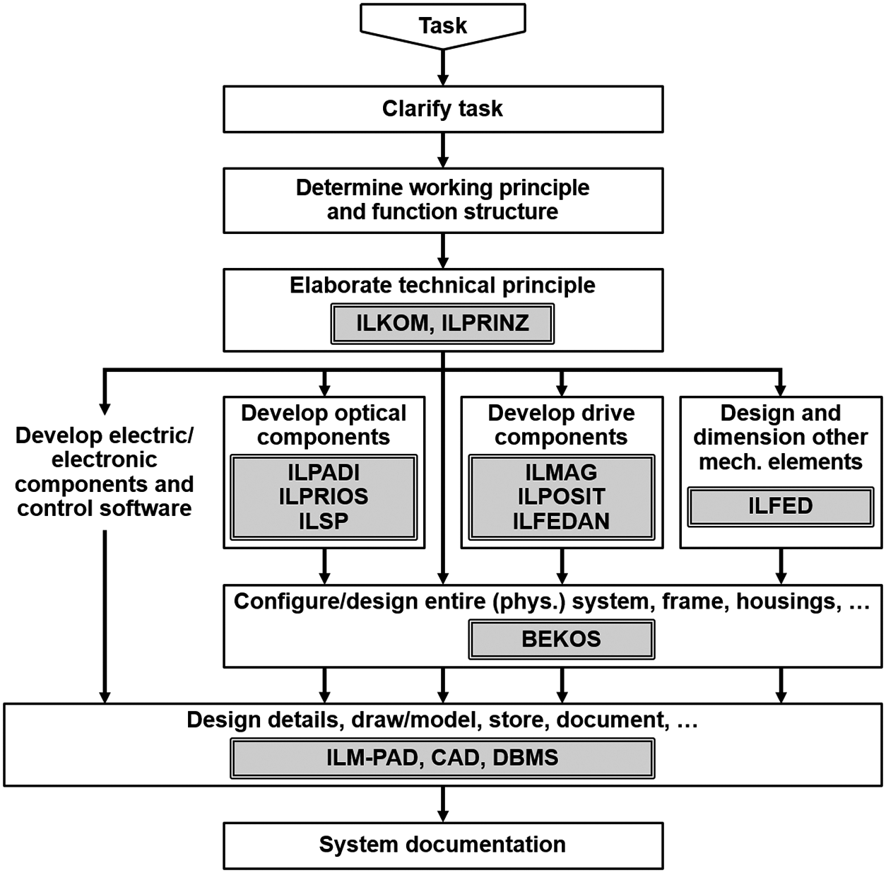
The Chair of Engineering Design (led by Günter Höhne, later Christian Weber), together with the Chair of Precision Engineering (led by René Theska), worked on subproject B02, “Mechanical Design of NPM-Machines”. The task of this subproject was to investigate and evaluate options for the general layout of the machine as well as for components and their interfaces (Figure 19). The dominating criterion – besides function – was precision of the solution. Besides experimental methods, the use of computer tools (virtual prototyping) in the context of design in precision mechanics was tested and, if necessary, improved upon (Lotz et al. Reference Lotz, Höhne, Hackel, Frank and Theska2007).
Morphological matrix of solution alternatives for different functional modules of the Nanopositioning and Nanomeasuring Machine (Höhne et al. Reference Höhne, Brix, Lotz, Theska, Frank and Hackel2006).

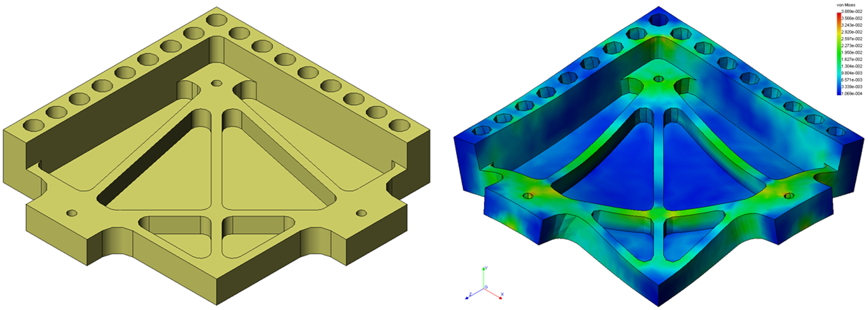
Special focus was laid on the design of the interferometric mirror (“stage mirror”) that has to be extremely precise (in order to allow for exact interferometric position and orientation measurements), has to provide a multitude of interfaces to other components, and must remain extremely insensitive to mechanical and thermal loads. For this task computer-supported optimisation methods were applied. The result is shown in Figure 20 (Lotz Reference Lotz2009).
Optimised interferometric mirror (“stage mirror”) of the Nanopositioning and Nanomeasuring Machine; CAD-model and simulation (Lotz Reference Lotz2009).
In the final period of CRC 622, subproject B02 took up earlier approaches of modelling and analysing tolerances in CAD (Stark & Weber Reference Stark and Weber1993; Stark Reference Stark1994; Britten & Weber Reference Britten and Weber1999; Thome & Weber Reference Thome and Weber2001), extended them to be able to model partially closed tolerance-loops and applied the method to problems occurring in the NPMM (Geis et al. Reference Geis, Husung, Oberänder, Weber and Adam2015; Husung et al. Reference Husung, Weber, Kroschel, Krone, Credo, Müller and Ackermann2016).
An initial version of the Nanopositioning and Nanomeasuring Machine (NPMM-1) was built and tested within CRC 622. It achieved a resolution of 0.1 nm over the positioning and measuring range (workspace) of 25 mm × 25 mm × 5 mm; it displayed the smallest positioning uncertainty (only a few nanometres) achieved so far, and the optical and tactile probes, which are only used as zero-point indicators, had reproducibilities < 1 nm. After the prototype NPMM-1, built, tested and optimised at TU Ilmenau in cooperation with SIOS Meßtechnik, the company built several more machines. They are operating successfully with various German and foreign research institutes, including the German National Metrology Institute (Physikalisch-Technische Bundesanstalt, PTB).
After the end of CRC 622 in 2013 a much bigger machine was designed and built (NPMM-200), having a positioning and measuring range (workspace) of 250 mm × 250 mm × 25 mm (Jäger et al. Reference Jäger, Manske, Hausotte, Müller and Balzer2016). In order to maintain nano-scale accuracies and resolutions (positioning uncertainty in this case < 30 nm), the whole machine had to be put into a vacuum. In 2019, a copy of NPMM-200 was delivered for use in the Institute of Technical Optics of the University of Stuttgart, financed by DFG.
2.4.2. Teaching: transfer and innovation
Early international cooperation in the area of teaching engineering design with special focus on precision engineering goes back well into the 1970s with the University of Niš, Yugoslavia, today Serbia (1972–1986), and the University of Setif, Algeria (1979–1983).
In the 1980s the State of Brazil released an international call to reform engineering education in the country. For the area of precision engineering, the bid of the company (!) Carl Zeiss in Jena won. Because of the close connections between Zeiss Jena and TH Ilmenau, the professors of Ilmenau – who had specialised in precision engineering anyway – were asked to fill and execute the programme.
Preparations started in the early 1980s; among other things, the teaching material of TH Ilmenau was translated into Portuguese. Between 1989 and 1991 the courses were then implemented at the pilot and partner university Universidade Federal de Santa Catarina (UFSC) in Florianopolis in the south of Brazil. Direct project coordinators were Günter Höhne on the German side and Prof. Walter Lindolfo Weingaertner on the Brazilian side.
During the project, Günter Höhne travelled to Florianopolis several times (1984, 1987, 1989). In preparation, he had been taught Portuguese and was able to teach classes himself. His final stay took place in the fall term 1989/1990. So it happened that he could follow what was going on in Germany at that time via the Brazilian TV: the so-called Fall of the Wall. When his time came to return to Germany in February 1990, the East German consulate in Brazil was already in a state of disintegration (although the German Democratic Republic formally still existed), and he could not get the necessary documents to travel back. In consequence, he went to the West German consulate where he was given a West German passport for the return journey.
In recognition of his merits, on 11th December 2008 Günter Höhne was awarded the honorary doctorate of the Universidade Federal de Santa Catarina (UFSC), Florianopolis, Brazil (Figure 21).
Günter Höhne receives the honorary doctorate of the Universidade Federal de Santa Catarina (UFSC), Florianopolis, Brazil, from Rector Prof. Alvaro T. Prata, 11th December 2008 [photography by René Theska].

After the pilot project with UFSC, similar projects – in teaching as well as research – were realised with two other Brazilian universities and later also a Peruvian university:
-
• Universidade Federal de Bahia (UFBA), Salvador, Brazil
-
• Universidade de Sao Paulo (USP), Sao Paulo, Brazil
-
• Pontificia Universidad Católica del Perú (PUCP), Lima, Peru
The cooperation between TU Ilmenau and Latin America is still quite close today, and has been for about 15 years coordinated by Prof. René Theska, Chair of Precision Engineering at TU Ilmenau (see www.tu-ilmenau.de/unionline/en/study/details/excellence-program-for-engineers-with-vision-1248).
As early as 1998 a combined on-site and teleteaching basic course on engineering design was established, along with multimedia elements (Höhne et al. Reference Höhne, Chilian and Henkel1999; Chilian et al. Reference Chilian, Lotter, Henkel and Höhne2000). The background was that besides TU Ilmenau there were study programmes on material science and technology also at the Friedrich-Schiller University in Jena and the Bauhaus University in Weimar. The students needed some introduction to engineering design, but neither Jena nor Weimar had lecturers and lectures in this field. Therefore, the course was held in Ilmenau and electronically transferred to Jena and Weimar via a high-speed connection.Footnote 14 Visual and audio communication both ways was possible (e.g. for students’ questions) – quite innovative 25 years ago. The teleteaching course is still in place today, now just connecting Ilmenau and Jena, as the Bauhaus University Weimar left the whole programme.
An anecdote is that Günter Höhne, lecturing in Ilmenau, once ejected a student in Jena who had been disturbing the class – and the student actually left the room.
2.4.3. Building bridges between scholars in Germany
Researchers in the area of Design Science in East and West Germany knew each other’s works but personal meetings were difficult during the years of the so-called Cold War. This slowly changed in the 1980s. For instance, Friedrich Hansen, at that time already in retirement, therefore in principle allowed to travel to the West, was invited to and took part in the 3rd International Conference on Engineering Design (ICED ’85) in Hamburg.Footnote 15
In the late 1980s, the first “official” meetings between East and West German design researchers could be organised – as long as they took place in East Germany. Involved were Gerhard Pahl (TH Darmstadt), Herbert Birkhofer (TH Darmstadt, successor of Gerhard Pahl), Wolfgang Beitz (TU Berlin), Klaus Ehrlenspiel (TU München, successor of Wolf G. Rodenacker), Hans-Joachim Franke (TU Braunschweig, successor of Karlheinz Roth), Johannes Müller (TU Karl-Marx-Stadt), Johannes Klose (TU Dresden), and Günter Höhne (TH Ilmenau). A first meeting of this group in West Germany was prepared for late 1989. This took considerable planning effort in order to get travel permissions for the East German scientists. However, when the date came the wall between East and West Germany had disappeared, and all the preparation efforts had become obsolete.
Based on these early initiatives Gerhard Pahl (TH, later TU Darmstadt) organised a series of workshops (1992–1993) within the framework of the “Ladenburger Diskurs” (Ladenburg Discourse, named after the hometown of the company of Carl Benz), funded by the Daimler and Benz Foundation (Pahl Reference Pahl1994). The researchers of TU Ilmenau contributed their experiences in knowledge demands of designers in Precision Engineering (Höhne Reference Höhne and Pahl1994).
As a follow-up, the workshop series “Bild und Begriff” (Image and Concept) was created, organised by Klaus Ehrlenspiel (TU München) and Johannes Müller (TU Chemnitz) (Figure 22). These workshops integrated psychologists into Design Science for the first time (at least for Germany): Winfried Hacker (TU Dresden), Werner Krause (Friedrich-Schiller University Jena) and Dietrich Dörner (Otto-Friedrich University Bamberg) which ultimately led to the topic of “Human Behaviour in Design” – still alive today as a Special Interest Group (SIG) of the Design Society (see https://human.designsociety.org/).
“Bild und Begriff” meeting 1994, Naupoldsmühle/Thuringia; selection of key participants: Herbert Birkhofer (TU Darmstadt, back row second from left), Klaus Ehrlenspiel (TU München, back row centre, beside H. Birkhofer), Horst Sperlich (TU Ilmenau, back row third from right), Werner Krause (FSU Jena, back row, far right, organiser of this meeting), Winfried Hacker (TU Dresden, front row far left), Johannes Müller (TU Chemnitz, front row centre), Günter Höhne (TU Ilmenau, front row right).

2.5. Developments 2007–2020
In 2007 Christian Weber was appointed the successor of Günter Höhne. Weber had established the Chair of Engineering Design/CAD at Saarland University, Saarbrücken/Germany, from scratch since 1989. His main motivation to move to Ilmenau was Ilmenau’s history and heritage in Design Science of which he was well aware. Weber was a founding member of the Design Society (2000), had served as a member of its Advisory Board (2001–2005), and was member of the Board of Management (2005–2013).
2.5.1. Research 2007–2020
The core research areas of the Chair of Engineering Design at TU Ilmenau were continued or extended.
Digital Mechanism and Gear Library
As already mentioned, the DMG-Lib project (Digital Mechanism and Gear Library, see related Section 2.4.1 and Figure 15 as an example), led by Torsten Brix, was extended from a national project (funded by DFG) into a European network of six European partners (Corves et al. Reference Corves, Brix, Döring and Ceccarelli2011). TU Ilmenau has the obligation to maintain DMG-Lib permanently, and its content is still being expanded. However, as the dedicated funding has run out and resources are now limited, progress is slower – mainly confined to contributions offered by users.
Collaborative Research Centre (Sonderforschungsbereich) 622
Also already mentioned, the work within the CRC 622 on Nanopositioning and Nanomeasuring Machines was continued (see sub-section further up). For the final period of CRC 622, new methods of modelling and analysing tolerances in the context of designing NPMM and precision machinery in general were investigated (Geis et al. Reference Geis, Husung, Oberänder, Weber and Adam2015; Husung et al. Reference Husung, Weber, Kroschel, Krone, Credo, Müller and Ackermann2016).
Audio-visual virtual reality in design
Extensive research on the use of VR techniques in Engineering Design was done. The means was the FASP shown in Figure 16, and the main focus was the integration of acoustic behaviour into product models at the so-called early stages of design. The main task was to find ways of representing and presenting the acoustics of products under development as early as possible by adding acoustic data to virtual prototypes (Springer et al. Reference Springer, Sladeczek, Scheffler, Hochstrate, Melchior and Fröhlich2006; Höhne et al. Reference Höhne, Husung, Weber and Brix2007). The background is that common practices in industry still mainly rely on experiments, thus requiring a comprehensive development and design process in the first place and building prototypes or even the product itself.
In the first 4–6 years, a number of questions were worked on, solutions presented and tried out (details not explained in this article for space reasons):
-
• How to integrate information about the acoustic behaviour of products and their components into the VR data structure? Details in: (Husung et al. Reference Husung, Höhne and Brix2007, Reference Husung, Sander, Weber and Höhne2008a, Reference Husung, Wall, Pöschl-Günther, Weber and Döring2013).
-
• How to represent (and present) directional characteristics of sound sources? Details in: (Husung et al. Reference Husung, Sander, Weber and Höhne2008a,Reference Husung, Metag, Höhne and Weber b, Reference Husung, Weber and Gramstat2009a,Reference Husung, Neher, Gramstat, Weber, Wender and Augsburg b), based on studies of Giron (Reference Giron1996).
-
• How to model and simulate the acoustic behaviour of products under real-time conditions as required in VR? Details in Husung et al. (Reference Husung, Neher, Gramstat, Weber, Wender and Augsburg2009b, Reference Husung, Kästner, Weber, Höhne and Brix2010a).
If products or systems are to be virtually assembled and their acoustic behaviour simulated and presented in VR, an additional question arises: how to model acoustic interdependencies inside the product/system, that is, how to model structure-borne sound propagation?
To answer this question an approach based on the four-pole (more general: multi-pole) theory was developed (Husung et al. Reference Husung, Weber and Gramstat2009a, Reference Husung, Kästner, Weber, Höhne and Brix2010a) as an extension of preliminary studies of Weber (Reference Weber1983, Reference Weber and Hubka1986, Reference Weber1991, Reference Weber2005a; Höhne & Weber Reference Höhne and Weber2007).
-
• Finally, sound reflection and sound isolation (e.g. from/by walls) have to be considered. In a small project, performed together with Dr. Robertas Mikalauskas of the Kaunas University of Technology, Lithuania, two methods for the simulation of isolation walls were discussed and compared: FEM simulation and a simplified, real-time calculation (Husung et al. Reference Husung, Mikalauskas, Weber and Kästner2010b).
The results of the work were tried out using machinery composed of several dedicated components. Figure 23 shows a pick-and-place unit (Husung et al. Reference Husung, Sladeczek, Rath, Brix, Brix and Weber2011) as an example of a completely virtual assembly, comprising geometry, motion and acoustics, the latter based on a combination of measured data of components and direct calculation (including structure-borne sound).
Pick-and-place machine – example of a virtual assembly including acoustics.

All these findings are extensively summed up in the dissertation (doctoral thesis) of Stephan Husung (Reference Husung2012). The prostep ivip AssociationFootnote 16 selected Stephan Husung’s thesis for their Scientific Award in 2012. 10 years later, after a period in industry, Husung would succeed Weber to the Chair of Engineering Design, by then called Chair of Product and Systems Engineering (see Section 2.6).
A moderately large project followed, funded by the Zeidler Research Foundation and executed in cooperation with the Institute of Product Development at the Karlsruhe Institute of Technology (IPEK/KIT), led by Prof. Albert Albers.
-
• In the first phase of the project, a wealth of acoustic data for car pass-by situations with constant speed according to ISO 362-1 (2009), generated on the roller test bench at IPEK/KIT utilising a novel measurement method (Robens Reference Robens2013), was deconstructed into the most relevant sound sources (Albers et al. Reference Albers, Landes, Behrendt, Weber, Siegel and Husung2015a), transferred into virtual models, then presented in the FASP (both visually and acoustically) (Figure 24; Husung et al. Reference Husung, Siegel and Weber2014).
Figure 24.Transfer of measured acoustic data (by IPEK/KIT) into virtual models (after Albers et al. Reference Albers, Behrendt, Landes, Weber, Husung and Siegel2016a).

-
• In the second phase of the project, more measurement data was produced at IPEK/KIT (beside conventionally driven cars also hybrid and electric vehicles), dynamic (transient) driving manoeuvres were derived by extensions of the virtual models and more complex traffic situations were built in VR (Albers et al. Reference Albers, Behrendt, Landes, Weber, Husung and Siegel2016a), including environmental influences like sound reflection at the walls of buildings (Figure 25).
Figure 25.Virtual audio-visual model of a traffic situation; screenshot of a generated audio-visual video clip as described in Siegel et al. (Reference Siegel, Weber, Mahboob, Albers, Landes and Behrendt2016).
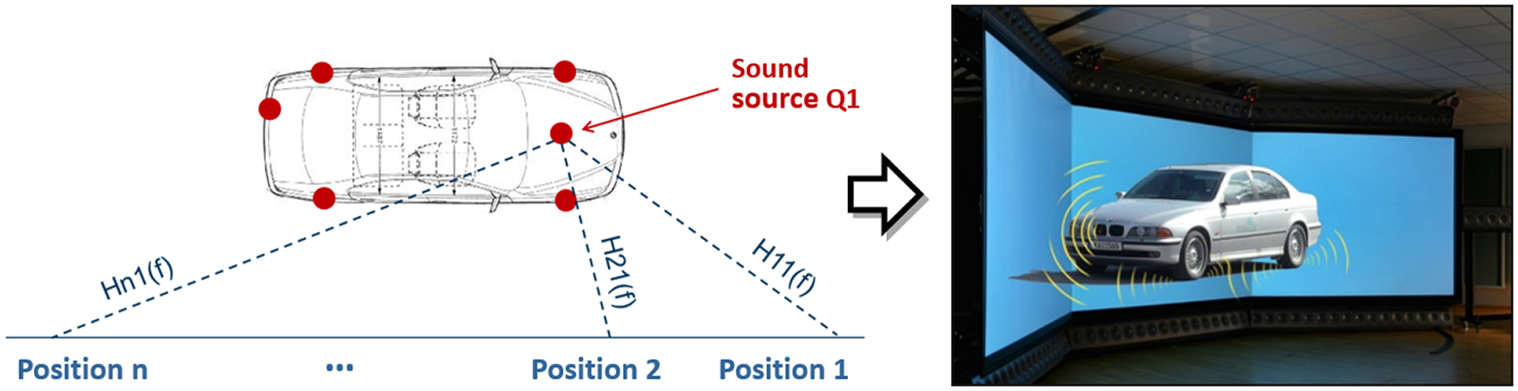

The new development in the second phase of the project was to utilise Artificial Neural Networks (ANNs) for the real-time simulation of the acoustic behaviour of cars, fed by measured data (with special means to delete noise generated by the test equipment itself). This included states “between” the measured data and, to a certain extent, also covered dynamic (transient) states (Siegel et al. Reference Siegel, Weber, Albers, Landes and Behrendt2017a,Reference Siegel, Weber, Albers, Landes and Behrendt b). While the approach worked very well for simulation, its usefulness for design purposes is questionable: an autoencoder concept was implied which means that the ANN algorithm determines the relevant parameters for the acoustic behaviour itself (unsupervised learning). The problem is that no relation exists between these – highly abstract – parameters and design parameters of the product.
Another larger project, funded by the German Federal Ministry for Economic Affairs and Energy, was “Acoustically Extended Virtualisation of Products and Production Processes” (AVP3), led by the Fraunhofer Institute of Digital Media Technologies (IDMT) in Ilmenau. In addition to the three academic partners (IDMT; Chair of Engineering Design at TU Ilmenau; Institute of Modelling and Computation at Technische Universität Hamburg-Harburg under the leadership of Prof. Otto von Estorff) the project comprised a number of industrial companies. The sub-project assigned to the Chair of Engineering Design at TU Ilmenau was the “Development of Extended Product Models for Virtual Product Development”; in this sub-project proposals were elaborated on how to enhance the so-called STEP standard (ISO 10303 n.d.) in order to capture and transport acoustic product information.
Systems engineering, MBSE
A larger project, funded by the DFG and performed in conjunction with scientists of the Chair of Media Production at TU Ilmenau, led by Prof. Heidi Krömker, was the project “User- and Task-Oriented Virtual Model for Product Development”, running from 2016 to 2021.
The basic tasks and ideas of the project were:
-
• Integration of VR techniques in product development processes to enable continuous evaluation of a product under development:
The solution here was to apply systems engineering concepts, especially Model-Based Systems Engineering (MBSE) using the Systems Modelling Language (SysML; ISO/IEC 19514 2017), as a means to model the VR elements and their interrelations. Thus, both the confrontation of the product with different life phases and the increasing details along the product development process would be captured.
The MBSE models would have to control the VR presentation. However, these models do not contain behaviour per se, especially under real-time requirements in VR. Therefore, means to link the MBSE models with a dedicated physics computation software (physics engine) were developed (Figure 26; Mahboob et al. Reference Mahboob, Husung, Weber, Liebal and Krömker2019a). The integration of the physics engine and SysML behaviour models was performed in such a way that the physics engine can later also be replaced by any domain-specific simulation tool (as long as this tool meets real-time requirements).
-
• Reducing the effort to create VR models, enhancing their re-use:
The solution concept here was a dissection of the VR- and MBSE-model into the product, environment and actor(s) sub-models that could be re-used and re-combined to form different use cases (Mahboob et al. Reference Mahboob, Weber, Husung, Liebal and Krömker2017). For example, putting different product (model) alternatives into the same environment (model), or sending the same product (model) through different environments (e.g. defined by the different life phases of the product like manufacturing and assembly, use, maintenance) (Figure 27; Mahboob Reference Mahboob2020).
One limitation: although the actor model was included inside the methodological foundation of the project and first investigations on its realisation were performed, for reasons of limited time and resources it could not be implemented. A standard VR interaction device was used as its proxy.
-
• During the project, another issue came up and was addressed: making VR models independent of particular VR technologies and systems:
In the end, a generic description of VR models was developed that allowed the (nearly) identical VR model to be sent to different VR systems: CAVE, Powerwall, Head-Mounted Display (HMD), even smartphones (sVR). The latter was quite new at the time, especially as the tracking of the user relative to the VR scene was done using the inbuilt camera of the smartphone (Mahboob et al. Reference Mahboob, Husung, Weber, Liebal and Krömker2019b).
Flow of information between different tools during VR simulation (Mahboob et al. Reference Mahboob, Husung, Weber, Liebal and Krömker2019a).

Information about the actor and the environment from product life phases (Mahboob Reference Mahboob2020).
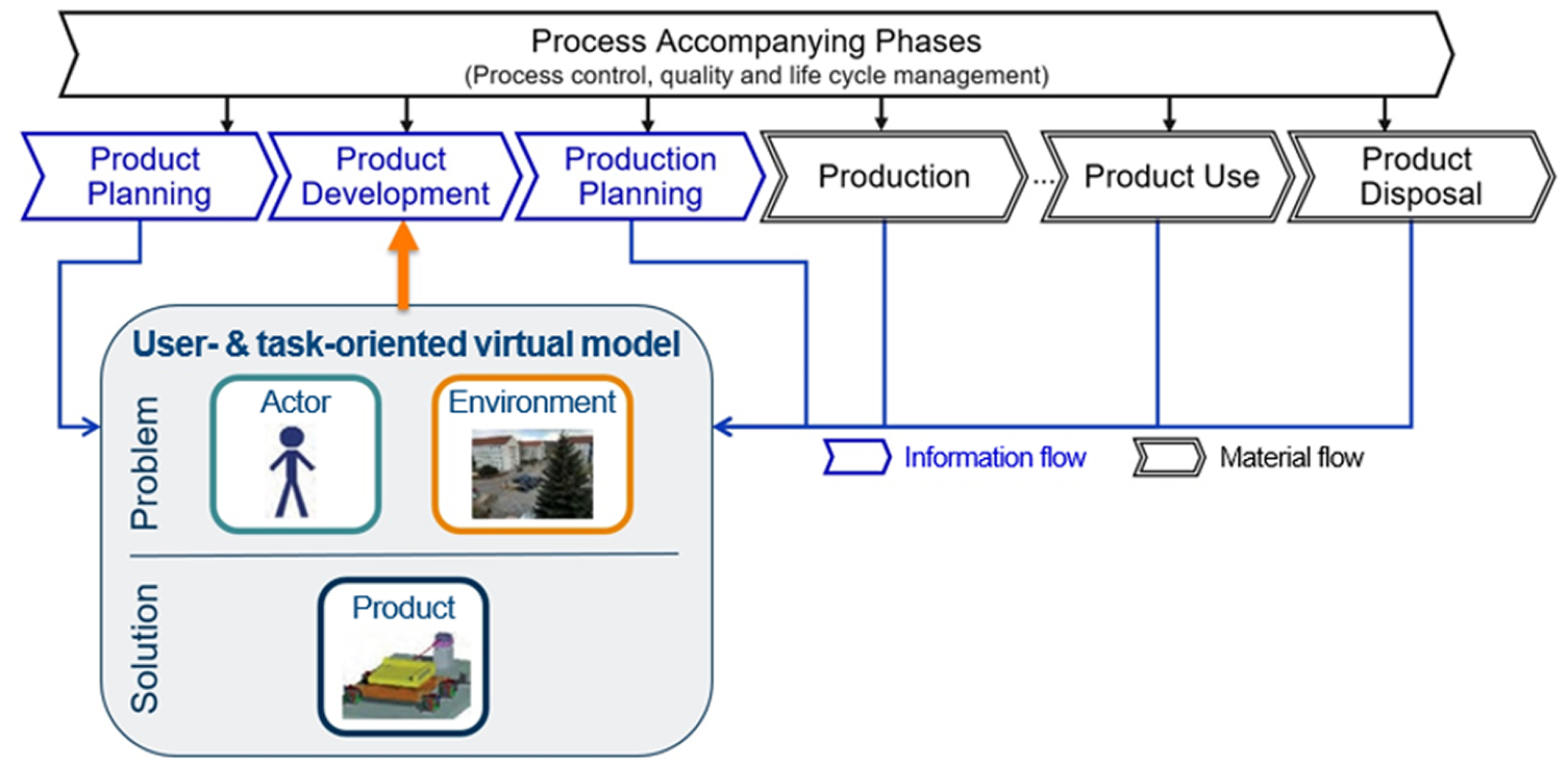
The results are summarised in the dissertation (doctoral thesis) of Atif Mahboob (Reference Mahboob2020). The thesis was awarded the 2021 Scientific Award of the prostep ivip Association.16
Modelling products and product development based on characteristics and properties (CPM/PDD)
When Christian Weber came to Ilmenau in 2017, he brought along some additional theoretical approaches. One of those was work on the four-pole (more general: multi-pole) theory as a means to model mechanical and mechatronic systems (Weber Reference Weber1983, Reference Weber and Hubka1986, Reference Weber1991, Reference Weber2005a; Höhne & Weber Reference Höhne and Weber2007). As was already mentioned before (see sub-section “Audio-visual virtual reality in design”), this went into certain parts of modelling the acoustic behaviour of products.
Another approach was modelling products and product development processes based on characteristics (design parameters) and properties (behaviour parameters) of products, first ideas published in Weber & Werner (Reference Weber and Werner2000), extensions and additional investigations shown in Weber (Reference Weber2005b, Reference Weber and Krause2007, Reference Weber2008, Reference Weber and Birkhofer2011, Reference Weber, Chakrabarti and Blessing2014). In the course of developing the approach, the whole concept was called “CPM/PDD”: Characteristics-Properties Modelling for the product modelling part, and Property-Driven Development for explaining product development processes.
The CPM/PDD approach is based on the distinction between the characteristics (in German: Merkmale) and properties (Eigenschaften) of a product:
-
• Characteristics (Ci) describe what the product consists of and how it looks: part structure, shape, dimensions, materials and surface specifications of all parts. The concept is closely related to what the Ilmenau researchers Hansen and Sperlich defined as “Gestalt” much earlier (Hansen Reference Hansen1974/1976/1985; Sperlich Reference Sperlich1983).5
The important thing is that only these can be directly influenced or determined by the designer.
-
• Properties (Pj) describe the product’s behaviour: function, weight, safety and reliability, aesthetic properties, manufacturability, assemblability, testability, environmental friendliness, cost, and – depending on the type of product and time (!) – maybe much more. Later, a distinction is made between the required and the as-is properties at any given state of the design process. It should be borne in mind that the number of relevant properties required of a product has been continuously increasing over the last two to three decades.
The properties can not be directly influenced by the designer, only via the characteristics (and, if permitted, by changing the external conditions to which the artefact is subjected).
The characteristics are very similar to “internal properties” as introduced by Hubka & Eder (Reference Hubka and Eder1996) and what is called “design parameters” in Suh (Reference Suh1990, Reference Suh2001). The properties are related to the “external properties” in Hubka & Eder (Reference Hubka and Eder1996), and to the “functional requirements,” according to Suh (Reference Suh1990, Reference Suh2001). For reasons not discussed here, the authors prefer to use the nomenclature “characteristics/properties” as defined by Andreasen (Reference Andreasen1980). The concept of properties, as used here, is also related to the “affordance” approach (Maier & Fadel Reference Maier and Fadel2001, Reference Maier and Fadel2009).
Between characteristics and properties two main relationships exist:
-
• Synthesis: based on given, that is, required, properties, the product’s characteristics are established and appropriate values assigned.
Synthesis is the main task of product development/design: the requirements are, in principle, a list of required properties; the task of the designer is to find appropriate solutions, that is, an appropriate set of characteristics that meet the requirements. In many practical cases, the requirements already contain certain characteristics; however, this means that some known partial solutions (solution patterns) are set from the beginning.
-
• Analysis: based on known/given characteristics (design parameters) of a product, its properties (its behaviour in relevant dimensions) are determined or – if the product does not yet exist – predicted.
During product development/design also many analysis operations are required: in all stages of the development process, they serve the purpose of checking whether the as-is properties of the solution actually meet the required properties.
Based on these fundamentals (all product-related, therefore part of CPM), the development/design process (PDD) can be expressed as cycles of synthesis (always first!), analysis and evaluation steps (Figure 28):
-
• The process and every cycle within it always starts with a synthesis step, based on the required properties (PRj, Soll-properties) or the current deviations between as-is and required properties (see below). Via appropriate synthesis methods/tools, the characteristics of the solution (Ci) are determined. In original design (New Product Development, NPD) this may only be a few characteristics in the beginning (the famous “first sketch” of the solution). In practice, this is often done by adopting partial solutions from previous designs, catalogues or new technologies (= solution elements/patterns, Weber Reference Weber2005b; Weber & Husung Reference Weber and Husung2016 – closely related to the concept of Product Generation Development according to (Albers et al. Reference Albers, Bursac and Wintergerst2015b)). From cycle to cycle the number of characteristics that are fixed will increase (“detailing” of the solution).
-
• In the second step of each cycle, the properties (Pj, Ist-properties) resulting from the present solution state are analysed, based on the characteristics established so far. Appropriate analysis methods/tools are needed for this step. What is “appropriate” will, however, change along the development/design process because the solution becomes ever more detailed. The spectrum of methods/tools is quite wide: experience/guesswork, simplified calculations, physical tests, computer tools, and so forth.
-
• In the third step, the analysis results of the previous step (Pj, Ist-properties) are used to determine the deviations against the required (Soll-) properties (PRj). The result of the comparison (ΔPj) reveals both already sufficiently realised and deficient properties of the design in its current state.
-
• The designer now has to run an overall evaluation: identify the main issues and decide how to proceed, that is, pick out the property or properties to attack next and select appropriate methods and tools for the subsequent synthesis-analysis-evaluation cycle.
It should be noted that this overall evaluation is the actual driver of the whole product development/design process: If the overall view on the current deviations delivers entirely satisfactory results the process may end. If the results are not satisfactory another cycle has to be started. “Satisfactory” means here that one cannot expect to bring the differences between all as-is and required properties (ΔPj) to zero; instead, the designer always has to find a compromise.
The product development/design process scheme according to the CPM/PDD approach.
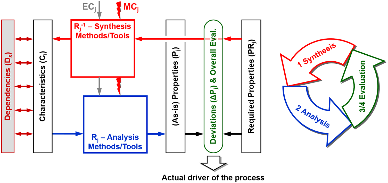
The scheme of product development/design processes according to the CPM/PDD approach (Figure 28) contains some more elements; they cannot be explained in detail here but should at least be briefly mentioned:
-
• Dependencies (Dx) between characteristics: designers are familiar with these types of dependencies, for example: geometric or spatial relations between elements, relations between tolerances (“fits”), surface and material pairings, and even conditions of existence (e.g. certain components of the solution requiring or prohibiting others). Today, geometric and spatial dependencies can be captured and administered by parametric CAD or PDM/PLM systems; however, the other types of dependencies are usually outside these systems.
-
• External conditions (ECj): the results produced by synthesis and analysis methods/tools depend not only on the product’s properties or characteristics but also on external conditions, for example: functional and maybe other properties like usability, comfort and safety depend on the use cases taken as a basis; manufacturability depends on manufacturing systems; eco-friendliness depends – among other things – on the existence of take-back and/or recycling systems. The ECs play the role of constraints under which the designer has to work and the solution has to function.
In most cases, the ECs are set from the beginning of the product development process. However, sometimes the product and the external conditions can be (or have to be) designed simultaneously.
-
• Modelling conditions (MCj): practically all synthesis and analysis methods/tools are based on preconditions which are neither part of the product (characteristics, properties) nor part of the External Conditions. Some examples: load or other operational conditions implied in physical tests (sometimes quite controversial issues, see debates about car test cycles to determine fuel consumption and emissions for conventionally driven cars or the operating ranges of battery-electric vehicles); element types and mesh granularity of a finite element analysis. This may become a problem, especially with computer tools if the Modelling Conditions are hidden in the software.
The CPM/PDD approach influenced the research work at the Chair of Engineering Design of TU Ilmenau (Husung Reference Husung2012; Erbe Reference Erbe2013; Resch Reference Resch2016; Hesse Reference Hesse2020; Scheler Reference Scheler2020; Mahboob Reference Mahboob2020) and, before that, also at Saarland University, Christian Weber’s former affiliation (Steinbach Reference Steinbach2005; Deubel Reference Deubel2007; Burr Reference Burr2008; Müller Reference Müller2008; Köhler Reference Köhler2009; Conrad Reference Conrad2010; Wanke Reference Wanke2010). It also sparked off more fundamental thoughts on the virtualisation of product models and their use in product development and design (Weber & Husung Reference Weber and Husung2011), it is still a topic today at the re-named Chair of Product and System Engineering, led by Stephan Husung, and it has found positive reception.
Cooperation with industry
Many projects with industry were carried out, most of them with small and medium-sized local companies. As is good practice at TU Ilmenau, quite often students were involved in these projects (via diploma/bachelor/master theses), not only to cut cost but also as an extremely effective way of teaching practice-related content. In the area of Virtual Reality (VR) applications, some larger projects were accomplished that also taught the researchers lessons (e.g. about the use and usability of VR in design reviews). As is often the case, not much can be disclosed about these industrial projects, with the exception of a joint publication about a mobile robot of which the function and efficiency were studied in VR before the object was actually built and brought to the market (Husung et al. Reference Husung, Rössel, Weber, Henkel and Roth2009c).
Ilmenau’s work set into perspective
In recent years, the approach of modelling products and product development processes based on characteristics (design parameters) and properties – CPM/PDD – can be seen as the most general of Ilmenau’s contributions to Design Science. Put into perspective, it is one of several extended or new explanations of designs and designing (both descriptive and prescriptive) that came up in the 1990s and early 2000s. These approaches were based on the results achieved in the early 1950s until the late 1970s – called the “experiential” and “intellectual phases” in Wallace & Blessing (Reference Wallace and Blessing1999). The extended and new works were not entirely “experimental” according to Wallace & Blessing (Reference Wallace and Blessing1999), but moving into this direction.
Many of the more recent works relate to and support each other, a result of considerably increased worldwide discussions enabled by the Design Society. Without going into details, some of these extended or new approaches (besides CPM/PDD) are:
-
• Axiomatic Design of Nam P. Suh (Reference Suh1990, Reference Suh2001)
-
• Function-Behaviour-Structure (FBS) Model of John Gero, first version published in Gero (Reference Gero1990)
-
• The Concept-Knowledge (C-K) Theory of Armand Hatchuel and Benoît Weill, first published in Hatchuel & Weill (Reference Hatchuel, Weil, Folkeson, Gralén, Norell and Sellgren2003)
-
• Several notable contributions of the Institute of Product Development (IPEK) at the Karlsruhe Institute of Technology (KIT) under the leadership of Albert Albers:
-
– The Contact and Channel Model (C&CM) (Matthiesen Reference Matthiesen2002; Albers & Alink Reference Albers and Alink2008)
-
– The SPALTEN Method (Albers et al. Reference Albers, Saak and Burkardt2002, Reference Albers, Burkhardt, Meboldt and Saak2005)
-
– The concept of Product Generation Development (Albers et al. Reference Albers, Bursac and Wintergerst2015b)
-
– The Integrated Product Engineering Model (iPeM) (Albers et al. Reference Albers, Reiss, Bursac and Richter2016b)
-
A good overview over most of the mentioned approaches is presented in Chakrabarti & Blessing (Reference Chakrabarti and Blessing2014). In this book, the role of theories, models and methodologies in Design Science is also discussed in a more general manner.
After a very early attempt in Andreasen & Hein (Reference Andreasen and Hein1987), the focus shifted from “Design” to “Integrated Product Development” and to more flexible approaches. To name just the German contributions published as books: (Ehrlenspiel Reference Ehrlenspiel1995; Lindemann Reference Lindemann2005/2009; Gausemeier et al. Reference Gausemeier, Lanza and Lindemann2012; Ehrlenspiel & Meerkamm Reference Ehrlenspiel and Meerkamm2013; Vajna Reference Vajna2020).
In the new century/millennium, the idea of Design as a Science was taken up again (Weber & Birkhofer Reference Weber and Birkhofer2007), with very influential publications by Horváth (Reference Horváth2004) and Papalambros (Reference Papalambros2015): This topic is discussed in the Special Interest Group (SIG) on Design Theory of the Design Society (see https://theory.designsociety.org/). (Hatchuel et al. Reference Hatchuel, le Masson, Reich and Subrahmanian2018) give a good overview of the work in this SIG (until 2018).
As a new approach to design research (Blessing & Chakrabarti Reference Blessing and Chakrabarti2009) presented a Design Research Methodology (DRM). This concept has had a considerable influence on the activities of design researchers worldwide; it is also the basis of the Summer School on Engineering Design Research (SSEDR), an international PhD course running annually since 1999 and endorsed by the Design Society, described further below.
Finally, the last 20 years have brought new activities in the field of Human Behaviour in Design, e.g. addressed in the Design Society’s Special Interest Group (SIG) of the same name (see https://human.designsociety.org/). A good overview over this area is presented in the book (Frankenberger et al. Reference Frankenberger, Badke-Schaub and Birkhofer2015). New analysis methods can bring new insights in this area (see e.g. Carbon Reference Carbon2019; Gero & Milovanović Reference Gero and Milovanović2020; Hay et al. Reference Hay, Cash and McKilligan2020). However, it must be admitted that after the activities in the late 1980s and early 1990s (see Section 2.4.3) Ilmenau’s contributions to Design Science have had no particular focus here.
2.5.2. Teaching: engineering design courses in the 21st century
Teaching followed the guideline as already established in the early days of the Chair of Engineering Design (see Table 4). The courses offered (consisting of lectures, exercises and project work) are listed in Table 6.
Chair of Engineering Design at TU Ilmenau, teaching programme ca. 2017
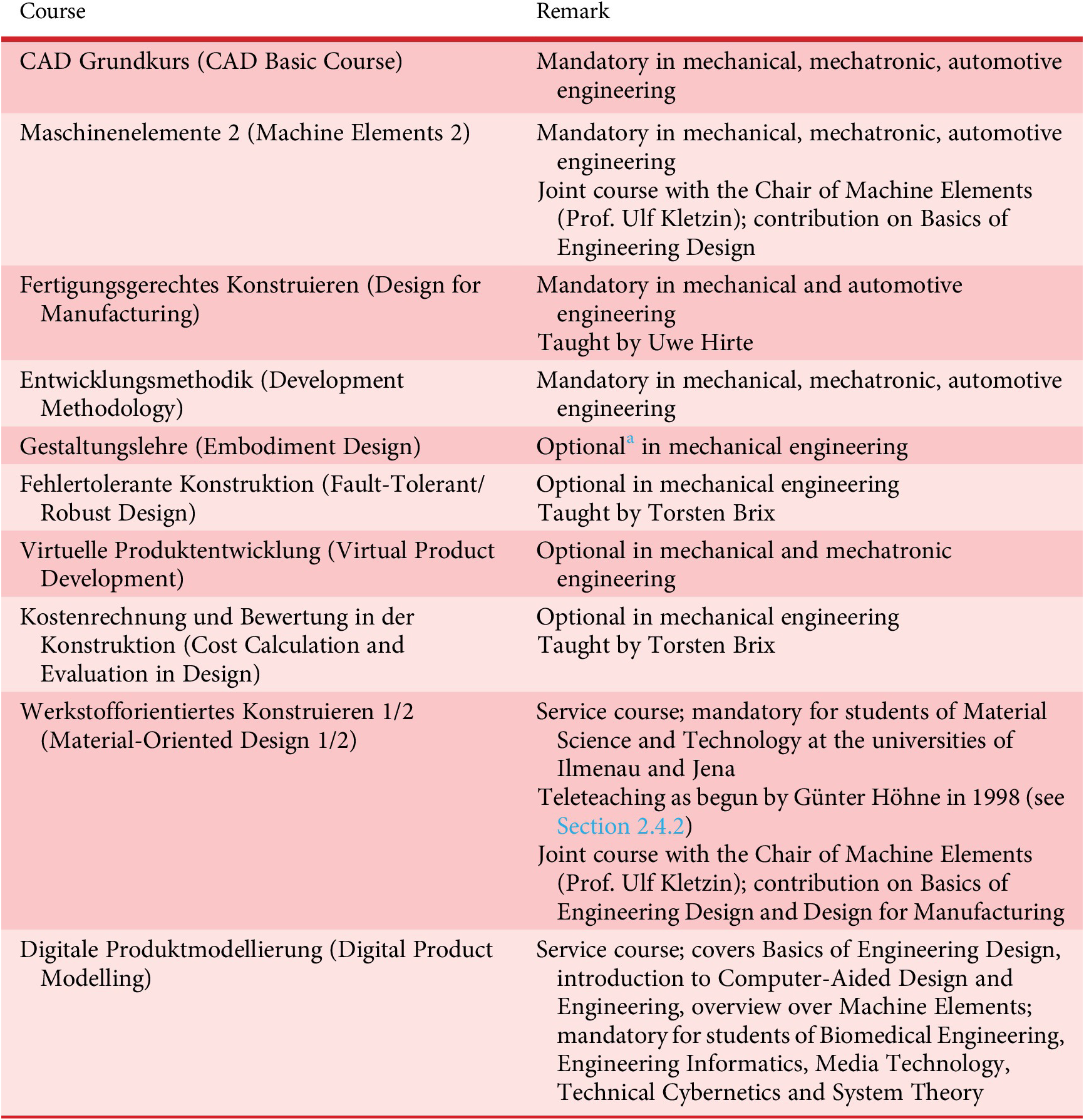
a “Optional” means that the course is mandatory only in a particular specialisation of the study programme mentioned. Usually, it is also an elective in other specialisations and other programmes.
Table 6 lists the contributions to the design education provided by the Chair of Engineering Design (today Chair of Product and Systems Engineering, Prof. Stephan Husung). More courses on wider topics are provided on Machine Elements (Chair of Machine Elements, Prof. Ulf Kletzin) and on Precision Engineering (Chair of Precision Engineering, Prof. René Theska).
Since 2020 some of the courses had to be changed from “mandatory” to “optional” or had to be merged because of restrictions posed by the so-called Bologna process. Unfortunately, this leaves some design-related courses (that are considered to be strenuous and difficult) un-attended and design-related knowledge un-taught.
Between 2000 and 2022 Christian Weber was engaged in the Summer School on Engineering Design Research (SSEDR), an international PhD course organised by Mogens M. Andreasen (Technical University of Denmark (DTU), Lyngby/Copenhagen, until 2016), Lucienne T.M. Blessing (TU Berlin, later Université du Luxembourg, then Singapore University of Technology and Design), Daniela C.A. Pigosso (DTU, since 2017) and Gaetano Cascini (Politecnico di Milano, since 2020). The course has different locations every year, usually rather remote sites and hosted by colleagues of the Engineering Design community across Europe. In the years 2008, 2013, 2014 and 2017 the course was hosted by TU Ilmenau (taking place in a remote location nearby but involving visits to the university).
2.6. Current activities
At the beginning of 2021, Stephan Husung was appointed as chair of the group. After his doctorate (Husung Reference Husung2012), he worked for several years in industry before returning to TU Ilmenau. The Chair was now re-named “Product and Systems Engineering” because of current and future needs in product development.
2.6.1. Current research activities
Current industrial demand and revised research clusters
Industry has a growing demand for comprehensive solutions to technical problems of high (and still growing) complexity (Husung et al. Reference Husung, Weber, Mahboob, Krause and Heyden2022a). In most cases, solutions for these problems cannot be realised by technical products alone, and complementary services are increasingly required. In development, products and services must be created concurrently, based on the given requirements and constraints. It can be observed that product and service development no longer ends with production and delivery, but that solutions must be further developed (e.g. “upgraded”) throughout their entire life. In addition to the focus on holistic solutions, the number of required properties of products and services still increases, and their priorities are currently shifting, sometimes dramatically. Examples of properties now prioritised above all are sustainability, safety and security. In the context of sustainability, among other things, information from all product life phases (e.g. for the so-called Scope 3 of the product carbon footprint, that is, indirect emissions that occur either in the upstream supply chain or during product use) must increasingly be collected and evaluated in a consolidated manner for the evaluation of solutions. However, sustainability cannot be achieved by adapting products alone. Business models must also be adapted and expanded.
The demands described above lead to an adaptation and expansion of research activities, and the research clusters shown in Figure 29 have emerged.
Research Clusters of the Chair of Product and Systems Engineering (PSE).
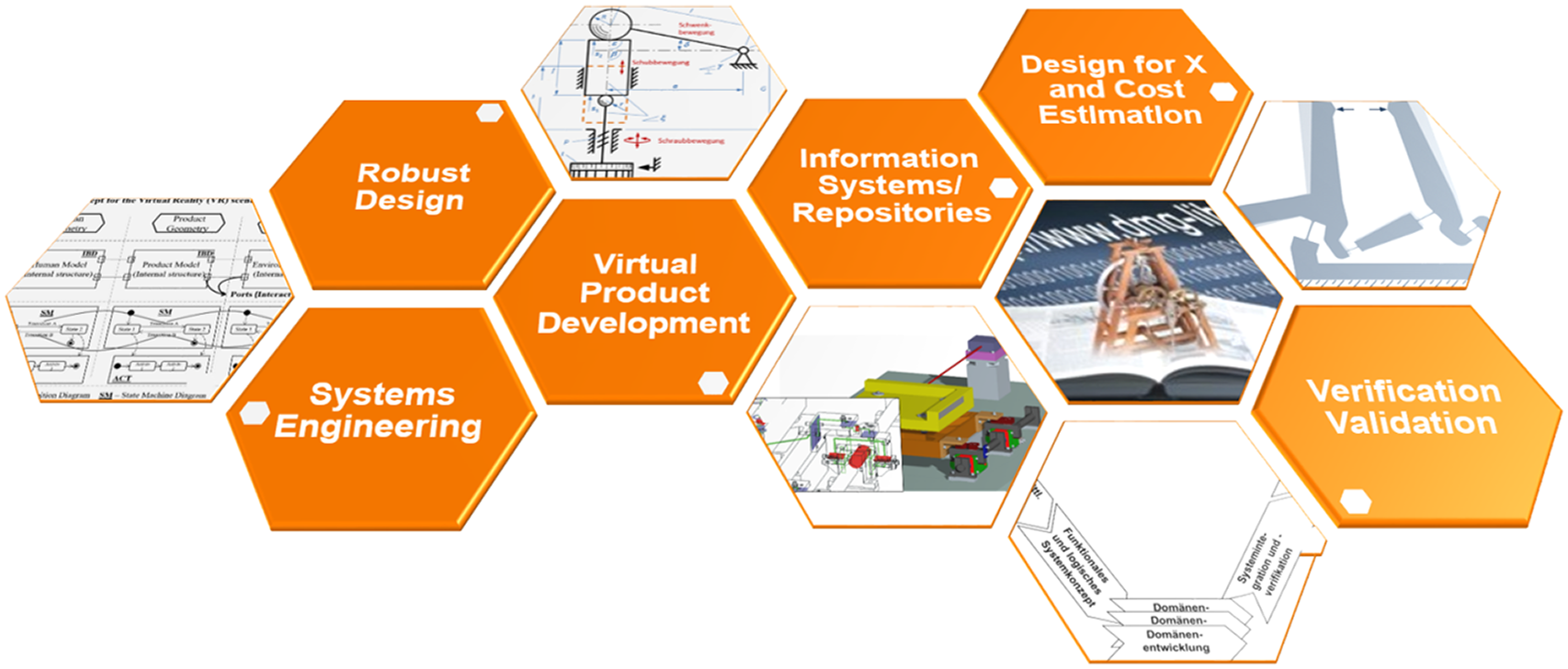
In the following sections, selected clusters will be presented in more detail.
Systems engineering, MBSE
The research activities on Systems Engineering and MBSE were enhanced. In the appropriate research cluster, they now focus on the design and support of holistic, cross-domain system development processes (problem-solving processes) from requirements identification and analysis to verification/validation of solutions. Processes, methods and models are developed specifically for the demands in the development and design process. Technical solutions that meet the above-mentioned demands often comprise mechatronic or cybertronic products. These products are described in development by systems that are developed at different levels. For this purpose, the systems are divided into sub-systems on the different levels. The required properties (of course, including the function) are decomposed and distributed to the sub-systems so that they can be developed and verified individually and independently. Figure 30 shows the decomposition process using the example of a precision motion system. When the sub-systems have reached a certain level of maturity, they are integrated into the superordinate system and finally into the overall system. Findings from the integration can lead to modifications of the distributed required properties, so that an iterative top-down and bottom-up process between the system levels is created (see Figures 30 and 31).
Top-down approach with the distribution of the required sub-functions to the sub-systems (Husung et al. Reference Husung, Weber and Mahboob2022b).

Interactions at the different levels of the system (Husung et al. Reference Husung, Weber and Mahboob2022b), expanded on the basis of Pohl et al. (Reference Pohl, Hönninger, Achatz and Broy2012).

Sub-systems sometimes already exist before development (e.g. from previous product generations, see Albers et al. Reference Albers, Bursac and Wintergerst2015b) or will be used multiple times in different products (e.g. a sensor is used in different measuring instruments). Re-using descriptions of the sub-systems that contain information about the implementation of sub-functions and other properties is important, as this re-use can help to improve quality and save time and resources during development. The re-use of any sub-system within a system requires the integration of top-down (system) and bottom-up (sub-system) descriptions (see Figure 31). The description and re-use of the sub-systems (bottom-up) inside multiple systems (top-down) are investigated in research projects using MBSE approaches (Husung et al. Reference Husung, Gerhard, Jacobs, Kowalski, Rumpe, Zeman and Zerwas2022c; Zerwas et al. Reference Zerwas, Jacobs, Kowalski, Husung, Gerhard, Rumpe, Zeman, Vafaei, König and Höpfner2022). In MBSE, the information about the system (use cases, requirements, states and related functions, solution elements) and development-related information (e.g. design decisions) is captured in models with static and dynamic aspects in a needs-oriented manner (Husung et al. Reference Husung, Weber, Mahboob and Kleiner2021). A main characteristic of these models is that they contain relations between modelling elements that are realising different aspects of the model (i.e. representing the system vs. a sub-system) (Husung et al. Reference Husung, Weber, Mahboob, Krause and Heyden2022a). The research questions address the necessary meta-models of the sub-system descriptions as well as the approaches to realise the synchronisation between top-down and bottom-up ways of working (see details in Mahboob & Husung Reference Mahboob and Husung2022 and the dissertation (Mahboob Reference Mahboob2020)). Further work complements MBSE approaches with knowledge graphs to transfer knowledge between projects (Faheem et al. Reference Faheem, Li and Husung2023; Mandel et al. Reference Mandel, Schwarz, Brix, Albers and Husung2023).
Robust design
Due to increasing product complexity and at the same time increasing quality demands of different stakeholders, research on Robust Design has found considerable interest during the last years. As part of these activities also TU Ilmenau has intensified its contributions, building on what has been called “Fault Tolerant Design” in Ilmenau (Brix & Husung Reference Brix and Husung2022). Projects are often performed in cooperation with partners in research and industry.
Today, Robust Design is considered in a dedicated Special Interest Group (SIG) of the Design Society (see https://robust.designsociety.org/). Its aims are to build a network of researchers and interested parties from industry on this important topic, to initiate discussions on research results, experiences and use cases, to harmonise terminology and to transfer findings to industry (Campean et al. Reference Campean, Uddin, Bridges, Fannon and Yildirim2022). Different industrial sectors are represented in the Robust Design SIG, so that in addition to Precision Engineering – the main focus in Ilmenau – challenges and approaches from production engineering, automotive and aerospace industries, medical and drug delivery devices and many others are addressed (Eifler et al. Reference Eifler, Campean, Husung and Schleich2023). In research, questions concerning all steps of the development process are discussed, in order to develop robust solutions in the context of the different requirements and external as well as internal influences (Eifler & Schleich Reference Eifler and Schleich2021; Husung et al. Reference Husung, Koch, Welzbacher, Kraus, Röhnert, Faheem and Kirchner2023; Li et al. Reference Li, Horber, Keller, Grauberger, Goetz, Wartzack and Matthiesen2023). Increasingly, approaches from Virtual Product Development are being used: from tolerance simulations (Heling et al. Reference Heling, Schleich and Wartzack2018) to Pareto optimisations (Bode et al. Reference Bode, Goetz, Schleich and Wartzack2023) and knowledge-based solutions (Faheem et al. Reference Faheem, Li and Husung2023; Walsh et al. Reference Walsh, Dong, Tumer and Brat2023). Thus, the variance of parameters can be taken into account early on, helping master the complexity of mechatronic or cybertronic solutions.
Extended design for X, Digital Twin
In order to meet the demands in product development, a wide spectrum of information from the later product life-phases is required. This includes, for example, information about sustainability, as already mentioned above. However, product development also requires, above all, knowledge about the use of the product or changes in its properties (e.g. due to ageing) in order to be able to develop the products even more efficiently in further product generations. Digital Twins are used, among other things, to capture and process instance-specific information (instance means a concrete product instance). In order to enable the Digital Twins to deliver the relevant information in a goal-oriented way, they must already be conceptualised and designed during product development. In joint research activities with TU Darmstadt, methods for the systematic development of Digital Twin solutions are being developed (Koch et al. Reference Koch, Husung, Röhnert, Mahboob, Frank and Kirchner2022; Husung et al. Reference Husung, Koch, Welzbacher, Kraus, Röhnert, Faheem and Kirchner2023).
In the Design for X cluster, optimisation methods and models are developed and validated for relevant properties. Example fields of application include the design of compliant systems (Harfensteller et al. Reference Harfensteller, Henning, Zentner and Husung2022) and of e-bike drive systems (Steck et al. Reference Steck, Husung and Hassler2022).
2.6.2. Teaching: current developments
Teaching will continue in the good tradition of Ilmenau interdisciplinary engineering design education (“Ilmenau School of Engineering Design,” see Table 4) with plenty of practical applications.
In order to prepare students for current and future challenges in product development and design, some additional aspects are being integrated into existing or addressed in new courses:
-
• Mechatronic System Development
-
• Agile Development Processes
-
• Application of new Technologies in Product Development
-
• Integrated Virtual Product Development
Studying means acquiring a wide range of technical, methodological and social skills for later professional life. In addition, students should be able to try out and develop themselves and thus get to know and develop their own strengths better. To make this learning process efficient, they need teaching and learning environments that are specifically tailored to the different needs. TU Ilmenau is already known for the excellent support provided to students by professors and scientific staff as well as the varied campus life.
In order to meet the need for flexible teaching and learning environments even better, future-oriented learning spaces are being created. Product development is a creative activity for finding solutions and assuring properties of the products that are being developed. Against this background, building up students’ competences in product development is of special importance in order to apply interdisciplinary knowledge and improve problem-solving skills. In addition, the acquisition of social skills and the ability to work in a team are key elements that must be conveyed in an interplay between teaching and learning. However, this is only possible if imparted object-related and methodological knowledge is actively applied by the students in practice-related exercises and projects, both individually and in (if possible interdisciplinary) teams.
For this purpose, a newly equipped learning room (“TU Ilmenau Lernwelt”), situated in the university library, has first been used for pilot projects in the winter term 2022/2023 and summer term 2023 (Watty et al. Reference Watty, Brix, Hirte and Husung2023). The test case was the course on Development Methodology (see Table 6) where project work in small teams has been used for a long time but could be enhanced by the new creative environment. The task of the students (in groups of 4) was to design a device that would automatically turn pages of books. The official inauguration of “TU Ilmenau Lernwelt” took place on 3rd February 2023.
3. Summary and conclusions
In the early 1950s, three researchers – Werner Bischoff, Friedrich Hansen and Arthur Bock – laid the fundaments of Design Science in Ilmenau. Their ideas had their origins in industry, at the Carl Zeiss company in Jena. After transfer to and further development in academia, they resulted in the “Ilmenau School of Engineering Design” (Ilmenauer Schule der Konstruktionslehre). Since then, the work has been carefully maintained and extended under the leadership of the authors of this article, often in cooperation with neighbouring Chairs at TU Ilmenau, most of which are also well aware of and cherish the “Ilmenau School of Engineering Design”.
Many issues have been addressed and contributions made: product description and modelling, design guidesheets, guidelines and catalogues, embodiment design, fault analysis and design review, automation of design activities and the use of computational means in design, at any given time applying current information technology. Existing as well as prospective demands of product development in practice are still seen as the foundation of developments, practical relevance of the results is the target.
In the last couple of decades, in addition to general design theories, procedures and methods, digital models and software solutions have become more and more important, for example for simulation, Virtual Reality applications, Systems Engineering and ontology-based representations.
Since the beginning in the early 1950s, the main focus in Ilmenau’s contributions to Design Science has always been precision engineering, including mechanical, electric, electronic, control, software, and optical components; applications in this area have particular importance today as they are crucial in extreme-UV lithography for microelectronics, a very important technique for the manufacture of the most advanced microelectronic devices.
Besides research and transfer to industry, teaching young engineers in design has always been executed with great care. Today, this issue is even more important than in the past for several reasons: new challenges like digitisation (of products and processes) and sustainability; increasing complexity of current and even more so future technical systems and processes (mechatronics, cybertronics, Product-Service Systems, broader view on them as socio-technical systems); interdisciplinary teams as the normal case of engineers’ work; last but not least, fighting shortages of young and skilled engineers in Germany (and other parts of Europe) for us to be well prepared to meet the challenges of the future and contribute to the benefit of mankind on this planet.


 Open access