


1 Introduction
Large-scale field measurements of snow avalanches (Sovilla, Sommavilla & Tomaselli Reference Sovilla, Sommavilla and Tomaselli2001; Sovilla & Bartelt Reference Sovilla and Bartelt2002; Sovilla, Burlando & Bartelt Reference Sovilla, Burlando and Bartelt2006) indicate that the dominant mechanism for entrainment and growth of an avalanche is via frontal ploughing into a layer of fresh snow. Sovilla et al. (Reference Sovilla, Burlando and Bartelt2006) showed that over eighteen events the avalanche mass typically increased by a factor of four, which had a significant effect on the flow dynamics as well as the run-out distance. The primary limiting factors on how much snow can be entrained are the structure of the snowpack and the amount of available material. Virtually all of the entrainment occurred at, or very close to, the flow front, with basal erosion by the body of the flow being much less significant. The process of frontal entrainment allows the avalanche to bulk up, and hence become much more destructive than the initial release. As well as eroding material at the front, snow may also be deposited at the rear, base and sides, and there is a subtle balance which determines whether there is overall growth or decay in the total avalanche mass. Deposition can also produce key qualitative changes to the flow dynamics, such as the formation of static levees at the flanks of the avalanche, which leave a trail in the deposit as shown in figure 1. This image also shows that between the levees there is a trough that has been incised down below the initial height of the snow cover, and which contains material that had previously been mobilized by the avalanche. The flow may also rapidly stop if the slope inclination changes and the avalanche decays away through mass deposition (Bartelt, Buser & Platzer Reference Bartelt, Buser and Platzer2007).
In order to investigate the effects of erosion and deposition experimentally, we perform small-scale analogue experiments on a rough inclined slope using carborundum particles of 280–
 $350~\unicode[STIX]{x03BC}\text{m}$
. For angles below
$350~\unicode[STIX]{x03BC}\text{m}$
. For angles below
 $\unicode[STIX]{x1D701}_{2}=47.5^{\circ }$
, the maximum angle for steady uniform flow, a static layer of erodible particles forms as the grains come to rest at a thickness
$\unicode[STIX]{x1D701}_{2}=47.5^{\circ }$
, the maximum angle for steady uniform flow, a static layer of erodible particles forms as the grains come to rest at a thickness
 $h_{stop}$
(Pouliquen Reference Pouliquen1999b
). Due to the hysteresis in the rough bed friction law (Daerr & Douady Reference Daerr and Douady1999; Pouliquen & Forterre Reference Pouliquen and Forterre2002), once the grains have stopped the slope can be inclined to a higher angle before the particles begin to flow again, and thicker layers of particles are stable provided their depth lies below
$h_{stop}$
(Pouliquen Reference Pouliquen1999b
). Due to the hysteresis in the rough bed friction law (Daerr & Douady Reference Daerr and Douady1999; Pouliquen & Forterre Reference Pouliquen and Forterre2002), once the grains have stopped the slope can be inclined to a higher angle before the particles begin to flow again, and thicker layers of particles are stable provided their depth lies below
 $h_{start}>h_{stop}$
. In the experiments, an avalanche is initiated on top of the erodible layer by releasing a finite mass of carborundum particles from a small aspect ratio hollow cylinder. Figure 2 shows a typical flow on a slope inclined at
$h_{start}>h_{stop}$
. In the experiments, an avalanche is initiated on top of the erodible layer by releasing a finite mass of carborundum particles from a small aspect ratio hollow cylinder. Figure 2 shows a typical flow on a slope inclined at
 $\unicode[STIX]{x1D701}=35.2^{\circ }$
to the horizontal and covered with a uniform-depth layer of erodible grains of thickness
$\unicode[STIX]{x1D701}=35.2^{\circ }$
to the horizontal and covered with a uniform-depth layer of erodible grains of thickness
 $h_{stop}$
. A long exposure time is selected so that the moving grains appear slightly blurred and the static grains can be seen in sharp focus. The avalanche has a crescentic shape, with a steep erosive front and a tail that decays more gradually in height. As the avalanche flows downslope, it continuously erodes particles at the front and deposits them at the rear, sides and base, to form a trail behind the flow, with an incised trough, that lies below the initial static deposit height and which is flanked by static raised levees. These are subtle features that can be seen in figure 2 due to the use of oblique lighting. In this case, the avalanche has organized itself into a three-dimensional, steadily travelling erosion–deposition wave (Edwards & Gray Reference Edwards and Gray2015) that can propagate indefinitely along the slope, so long as the erodible layer ahead of the wave does not change depth and the inclination remains the same. The formation of an incised trough and levees is closely similar to what was observed in the real snow avalanche in figure 1. This suggests that there is a strong link between the analogue experiments and real field-scale observations.
$h_{stop}$
. A long exposure time is selected so that the moving grains appear slightly blurred and the static grains can be seen in sharp focus. The avalanche has a crescentic shape, with a steep erosive front and a tail that decays more gradually in height. As the avalanche flows downslope, it continuously erodes particles at the front and deposits them at the rear, sides and base, to form a trail behind the flow, with an incised trough, that lies below the initial static deposit height and which is flanked by static raised levees. These are subtle features that can be seen in figure 2 due to the use of oblique lighting. In this case, the avalanche has organized itself into a three-dimensional, steadily travelling erosion–deposition wave (Edwards & Gray Reference Edwards and Gray2015) that can propagate indefinitely along the slope, so long as the erodible layer ahead of the wave does not change depth and the inclination remains the same. The formation of an incised trough and levees is closely similar to what was observed in the real snow avalanche in figure 1. This suggests that there is a strong link between the analogue experiments and real field-scale observations.
Small levees on either flank of an incised trough in the trail behind the main body of a snow avalanche at Jungeralm in Bad Gastein, Austria.

Oblique view of an erosion–deposition wave travelling downslope on a plane inclined at an angle
 $\unicode[STIX]{x1D701}=35.2^{\circ }$
to the horizontal. The right-hand side of the wavefront appears brighter due to oblique illumination from the downslope end of the plane. A long time exposure has been used so that moving grains are blurred and the static regions are sharply in focus. The width of this avalanche is approximately 8.5 cm across the wave crest. Behind the elevated front of the flow lateral levees are deposited on either flank and between them a trough that is slightly beneath the level of the original deposit is left behind on the erodible bed.
$\unicode[STIX]{x1D701}=35.2^{\circ }$
to the horizontal. The right-hand side of the wavefront appears brighter due to oblique illumination from the downslope end of the plane. A long time exposure has been used so that moving grains are blurred and the static regions are sharply in focus. The width of this avalanche is approximately 8.5 cm across the wave crest. Behind the elevated front of the flow lateral levees are deposited on either flank and between them a trough that is slightly beneath the level of the original deposit is left behind on the erodible bed.

Permanent-form solitary waves on erodible beds were first observed by Daerr (Reference Daerr2001). Börzsönyi, Halsey & Ecke (Reference Börzsönyi, Halsey and Ecke2005, Reference Börzsönyi, Halsey and Ecke2008) made further observations and postulated a Burgers-type model, but unfortunately solitary
 $n$
-wave-type solutions decay in height with increasing time (Whitham Reference Whitham1974; Edwards & Gray Reference Edwards and Gray2015), so this approach cannot describe erosion–deposition waves. Clément et al. (Reference Clément, Malloggi, Andreotti and Aranson2007) developed a partial fluidization theory with two equations to describe the evolution of the flow thickness and an order parameter that governs the amount of fluidization. This model does have a family of solitary wave solutions, but the structure of the equations is radically different to those one might expect as a generalization of the shallow-water-like avalanche models that are conventionally used to model geophysical mass flows (e.g. Grigorian, Eglit & Iakimov Reference Grigorian, Eglit and Iakimov1967; Eglit Reference Eglit and Shahinpoor1983; Savage & Hutter Reference Savage and Hutter1989; Iverson Reference Iverson1997; Gray, Wieland & Hutter Reference Gray, Wieland and Hutter1999; Gray, Tai & Noelle Reference Gray, Tai and Noelle2003; Mangeney-Castelnau et al.
Reference Mangeney-Castelnau, Vilotte, Bristeau, Perthame, Bouchut, Simeoni and Yerneni2003).
$n$
-wave-type solutions decay in height with increasing time (Whitham Reference Whitham1974; Edwards & Gray Reference Edwards and Gray2015), so this approach cannot describe erosion–deposition waves. Clément et al. (Reference Clément, Malloggi, Andreotti and Aranson2007) developed a partial fluidization theory with two equations to describe the evolution of the flow thickness and an order parameter that governs the amount of fluidization. This model does have a family of solitary wave solutions, but the structure of the equations is radically different to those one might expect as a generalization of the shallow-water-like avalanche models that are conventionally used to model geophysical mass flows (e.g. Grigorian, Eglit & Iakimov Reference Grigorian, Eglit and Iakimov1967; Eglit Reference Eglit and Shahinpoor1983; Savage & Hutter Reference Savage and Hutter1989; Iverson Reference Iverson1997; Gray, Wieland & Hutter Reference Gray, Wieland and Hutter1999; Gray, Tai & Noelle Reference Gray, Tai and Noelle2003; Mangeney-Castelnau et al.
Reference Mangeney-Castelnau, Vilotte, Bristeau, Perthame, Bouchut, Simeoni and Yerneni2003).
Early models for snow avalanches (Briukhanov et al. Reference Briukhanov, Grigorian, Miagkov, Plam, Shurova, Eglit and Yakimov1967; Grigorian et al. Reference Grigorian, Eglit and Iakimov1967; Eglit & Demidov Reference Eglit and Demidov2005) recognized the importance of frontal entrainment and solved for the motion of the front by treating it as a shock wave separating a finite-depth solid-like erodible layer from a rapidly moving liquid-like avalanche. Mass and momentum jump conditions were then used to solve for the entrainment of mass and the speed of front propagation. This approach requires the moving interface between the static snow cover and the avalanche to be tracked as part of any computation. To avoid this, Eglit (Reference Eglit and Shahinpoor1983) proposed a model with more gradual erosion at the base of the avalanche, with the rate being proportional to the flow speed, which is highest at the front. Most current avalanche models try to incorporate erosion and deposition by introducing mass and momentum source terms into the depth-averaged mass and momentum balances (e.g. Bouchaud et al. Reference Bouchaud, Cates, Prakash and Edwards1994; Douady, Andreotti & Daerr Reference Douady, Andreotti and Daerr1999; Gray Reference Gray2001; Doyle et al. Reference Doyle, Huppert, Lube, Mader and Sparks2007; Tai & Kuo Reference Tai and Kuo2008; Gray & Ancey Reference Gray and Ancey2009; Iverson Reference Iverson2012; Tai & Kuo Reference Tai and Kuo2012) and sometimes to augment them with an energy balance equation (e.g. Bouchut et al. Reference Bouchut, Fernández-Nieto, Mangeney and Lagreé2008; Capart, Hung & Stark Reference Capart, Hung and Stark2015). These approaches are notoriously difficult since additional non-trivial empirical relations are required to close the models and there may be slow creep deep beneath the avalanche (Komatsu et al. Reference Komatsu, Inagaki, Nakagawa and Nasuno2001), which makes the interface between the flowing and static regions hard to define.
Recently Edwards & Gray (Reference Edwards and Gray2015) have developed a one-dimensional system of depth-averaged equations to model erosion–deposition waves, which combines the extended basal friction law of Pouliquen & Forterre (Reference Pouliquen and Forterre2002) with the depth-averaged
 $\unicode[STIX]{x1D707}(I)$
-rheology of Gray & Edwards (Reference Gray and Edwards2014). The avalanche is assumed to be either moving or static throughout its entire depth, with the basal friction law essentially determining which regions are in motion. Although this approximation is crude, in that it does not explicitly resolve the basal entrainment or deposition, Edwards & Gray (Reference Edwards and Gray2015) showed that it was able to predict accurately the amplitude, wavelength and coarsening dynamics of erosion–deposition waves that spontaneously form in a long channel from a continuous inflow. They observed that typical waves had a ratio of peak height to static layer depth of 2.6 and a typical mobile wavelength of 59 cm, which are both very similar to the waves observed by Takagi, McElwaine & Huppert (Reference Takagi, McElwaine and Huppert2011) in their low-inflow-rate experiments.
$\unicode[STIX]{x1D707}(I)$
-rheology of Gray & Edwards (Reference Gray and Edwards2014). The avalanche is assumed to be either moving or static throughout its entire depth, with the basal friction law essentially determining which regions are in motion. Although this approximation is crude, in that it does not explicitly resolve the basal entrainment or deposition, Edwards & Gray (Reference Edwards and Gray2015) showed that it was able to predict accurately the amplitude, wavelength and coarsening dynamics of erosion–deposition waves that spontaneously form in a long channel from a continuous inflow. They observed that typical waves had a ratio of peak height to static layer depth of 2.6 and a typical mobile wavelength of 59 cm, which are both very similar to the waves observed by Takagi, McElwaine & Huppert (Reference Takagi, McElwaine and Huppert2011) in their low-inflow-rate experiments.
A key element of the Gray & Edwards (Reference Gray and Edwards2014) theory is the introduction of a depth-averaged viscous term, which represents a singular perturbation to the equations. Strong support for this approach is provided by the fact that the depth-averaged
 $\unicode[STIX]{x1D707}(I)$
-rheology is also able to predict the cutoff frequency of roll waves (Forterre & Pouliquen Reference Forterre and Pouliquen2003; Forterre Reference Forterre2006) without the need for any additional fitting parameters, since the granular viscosity is fully determined (Gray & Edwards Reference Gray and Edwards2014). This contrasts with inviscid avalanche models that incorrectly predict the growth of granular roll waves at all frequencies above the critical Froude number,
$\unicode[STIX]{x1D707}(I)$
-rheology is also able to predict the cutoff frequency of roll waves (Forterre & Pouliquen Reference Forterre and Pouliquen2003; Forterre Reference Forterre2006) without the need for any additional fitting parameters, since the granular viscosity is fully determined (Gray & Edwards Reference Gray and Edwards2014). This contrasts with inviscid avalanche models that incorrectly predict the growth of granular roll waves at all frequencies above the critical Froude number,
 $Fr_{c}>2/3$
. Baker, Barker & Gray (Reference Baker, Barker and Gray2016a
) have generalized the depth-averaged
$Fr_{c}>2/3$
. Baker, Barker & Gray (Reference Baker, Barker and Gray2016a
) have generalized the depth-averaged
 $\unicode[STIX]{x1D707}(I)$
-rheology to two dimensions by using the principle of frame invariance. Their extended model is able to capture the depth-averaged downslope velocity profile that develops across a fully developed chute flow with either wall slip or zero velocity at the rough side walls. Again, this is something that the inviscid theory is unable to capture. Moreover, for sufficiently wide channels the reconstructed two-dimensional downslope velocity profile across the channel compares favourably with steady-state simulations using the full (non-depth-averaged)
$\unicode[STIX]{x1D707}(I)$
-rheology to two dimensions by using the principle of frame invariance. Their extended model is able to capture the depth-averaged downslope velocity profile that develops across a fully developed chute flow with either wall slip or zero velocity at the rough side walls. Again, this is something that the inviscid theory is unable to capture. Moreover, for sufficiently wide channels the reconstructed two-dimensional downslope velocity profile across the channel compares favourably with steady-state simulations using the full (non-depth-averaged)
 $\unicode[STIX]{x1D707}(I)$
-rheology (Jop, Forterre & Pouliquen Reference Jop, Forterre and Pouliquen2006), as well as with experimental measurements of the surface velocity.
$\unicode[STIX]{x1D707}(I)$
-rheology (Jop, Forterre & Pouliquen Reference Jop, Forterre and Pouliquen2006), as well as with experimental measurements of the surface velocity.
In this paper we focus on using the Baker et al. (Reference Baker, Barker and Gray2016a
) extension to the depth-averaged
 $\unicode[STIX]{x1D707}(I)$
-rheology to model three-dimensional erosion–deposition waves. Early observations of such waves started with Daerr & Douady (Reference Daerr and Douady1999) who triggered two types of avalanche behaviour on a rough bed with an erodible layer of grains. The static layer was prepared by pouring glass beads down a slope covered with a velvet cloth, which left a deposit of thickness
$\unicode[STIX]{x1D707}(I)$
-rheology to model three-dimensional erosion–deposition waves. Early observations of such waves started with Daerr & Douady (Reference Daerr and Douady1999) who triggered two types of avalanche behaviour on a rough bed with an erodible layer of grains. The static layer was prepared by pouring glass beads down a slope covered with a velvet cloth, which left a deposit of thickness
 $h_{stop}$
on a slope of inclination
$h_{stop}$
on a slope of inclination
 $\unicode[STIX]{x1D701}_{stop}$
. They observed that this static layer could be inclined to a higher angle
$\unicode[STIX]{x1D701}_{stop}$
. They observed that this static layer could be inclined to a higher angle
 $\unicode[STIX]{x1D701}_{start}$
before it would spontaneously start flowing again, i.e. there is hysteresis. For a small increase in the slope angle, between
$\unicode[STIX]{x1D701}_{start}$
before it would spontaneously start flowing again, i.e. there is hysteresis. For a small increase in the slope angle, between
 $\unicode[STIX]{x1D701}_{stop}$
and
$\unicode[STIX]{x1D701}_{stop}$
and
 $\unicode[STIX]{x1D701}_{start}$
, a small perturbation to the static layer at a single point created an avalanche that propagated downslope entraining mass and widening as it flowed. This left a triangular pattern in the deposit, which led Daerr & Douady (Reference Daerr and Douady1999) to name these phenomena ‘triangular’ avalanches. They also showed that on less stable slopes the avalanching region propagated upwards as well, so that eventually the whole erodible layer was set in motion.
$\unicode[STIX]{x1D701}_{start}$
, a small perturbation to the static layer at a single point created an avalanche that propagated downslope entraining mass and widening as it flowed. This left a triangular pattern in the deposit, which led Daerr & Douady (Reference Daerr and Douady1999) to name these phenomena ‘triangular’ avalanches. They also showed that on less stable slopes the avalanching region propagated upwards as well, so that eventually the whole erodible layer was set in motion.
Pouliquen (Reference Pouliquen1999a
) measured
 $h_{stop}$
as a function of the inclination angle
$h_{stop}$
as a function of the inclination angle
 $\unicode[STIX]{x1D701}$
, and performed experiments to determine the thickness
$\unicode[STIX]{x1D701}$
, and performed experiments to determine the thickness
 $h$
and the depth-averaged velocity
$h$
and the depth-averaged velocity
 $\bar{\boldsymbol{u}}$
during steady uniform flow. He found that all the experimental data collapsed with the scaling
$\bar{\boldsymbol{u}}$
during steady uniform flow. He found that all the experimental data collapsed with the scaling
 $Fr=\unicode[STIX]{x1D6FD}h/h_{stop}$
, where the constant of proportionality
$Fr=\unicode[STIX]{x1D6FD}h/h_{stop}$
, where the constant of proportionality
 $\unicode[STIX]{x1D6FD}=0.136$
. Note that Pouliquen (Reference Pouliquen1999a
) defined the Froude number as
$\unicode[STIX]{x1D6FD}=0.136$
. Note that Pouliquen (Reference Pouliquen1999a
) defined the Froude number as
 $Fr=|\bar{\boldsymbol{u}}|/\sqrt{gh}$
, where
$Fr=|\bar{\boldsymbol{u}}|/\sqrt{gh}$
, where
 $|\bar{\boldsymbol{u}}|$
was the depth-averaged speed and
$|\bar{\boldsymbol{u}}|$
was the depth-averaged speed and
 $g$
was the constant of gravitational acceleration. Using this relation to substitute for
$g$
was the constant of gravitational acceleration. Using this relation to substitute for
 $h_{stop}$
, Pouliquen (Reference Pouliquen1999a
) determined an empirical friction law for rough beds provided
$h_{stop}$
, Pouliquen (Reference Pouliquen1999a
) determined an empirical friction law for rough beds provided
 $Fr>\unicode[STIX]{x1D6FD}$
. Gray & Edwards (Reference Gray and Edwards2014) showed that although the rough bed friction law looks like a basal friction law it actually encodes the leading-order behaviour of the
$Fr>\unicode[STIX]{x1D6FD}$
. Gray & Edwards (Reference Gray and Edwards2014) showed that although the rough bed friction law looks like a basal friction law it actually encodes the leading-order behaviour of the
 $\unicode[STIX]{x1D707}(I)$
-rheology through the depth of the granular avalanche. Pouliquen & Forterre (Reference Pouliquen and Forterre2002) combined Pouliquen’s (Reference Pouliquen1999a
) dynamic rough bed friction law with the Daerr & Douady (Reference Daerr and Douady1999) concept that once the grains were stopped (i.e.
$\unicode[STIX]{x1D707}(I)$
-rheology through the depth of the granular avalanche. Pouliquen & Forterre (Reference Pouliquen and Forterre2002) combined Pouliquen’s (Reference Pouliquen1999a
) dynamic rough bed friction law with the Daerr & Douady (Reference Daerr and Douady1999) concept that once the grains were stopped (i.e.
 $Fr=0$
) flow could not start again until the higher angle
$Fr=0$
) flow could not start again until the higher angle
 $\unicode[STIX]{x1D701}_{start}$
was exceeded. For the intermediate regime
$\unicode[STIX]{x1D701}_{start}$
was exceeded. For the intermediate regime
 $0<Fr<\unicode[STIX]{x1D6FD}$
there was no further experimental information, so Pouliquen & Forterre (Reference Pouliquen and Forterre2002) suggested a power law extrapolation between the two laws.
$0<Fr<\unicode[STIX]{x1D6FD}$
there was no further experimental information, so Pouliquen & Forterre (Reference Pouliquen and Forterre2002) suggested a power law extrapolation between the two laws.
Pouliquen & Forterre (Reference Pouliquen and Forterre2002) applied their extended friction law to the release of a finite mass of granular material on a rough surface and found that an inviscid shallow-water avalanche model was able to predict accurately the position and time at which it stopped, as well as the overall spreading. They also performed the same experiment on a bed of erodible grains. In this configuration they found that the experimental avalanche spread out, and formed a drop shape similar to that observed by Daerr (Reference Daerr2001), with a sharp front and gradual decrease in height in the tail that propagated steadily downslope, eroding and depositing material as it flowed. On the other hand, their inviscid simulations predicted that the flow did not approach a steadily travelling wave. Instead, the computed solution spread out considerably more, so that it was thinner and faster than the experiment with a large almost constant thickness region. This may be an indication that the computation was partially locking onto the steady uniform flow solution to the intermediate flow regime found by Edwards & Gray (Reference Edwards and Gray2015). In the light of the successful prediction of the formation of two-dimensional steadily travelling erosion–deposition waves (Edwards & Gray Reference Edwards and Gray2015), using the depth-averaged
 $\unicode[STIX]{x1D707}(I)$
-rheology (Gray & Edwards Reference Gray and Edwards2014), this paper investigates whether their model is able to more accurately predict what happens in three dimensions.
$\unicode[STIX]{x1D707}(I)$
-rheology (Gray & Edwards Reference Gray and Edwards2014), this paper investigates whether their model is able to more accurately predict what happens in three dimensions.
2 Experimental observations
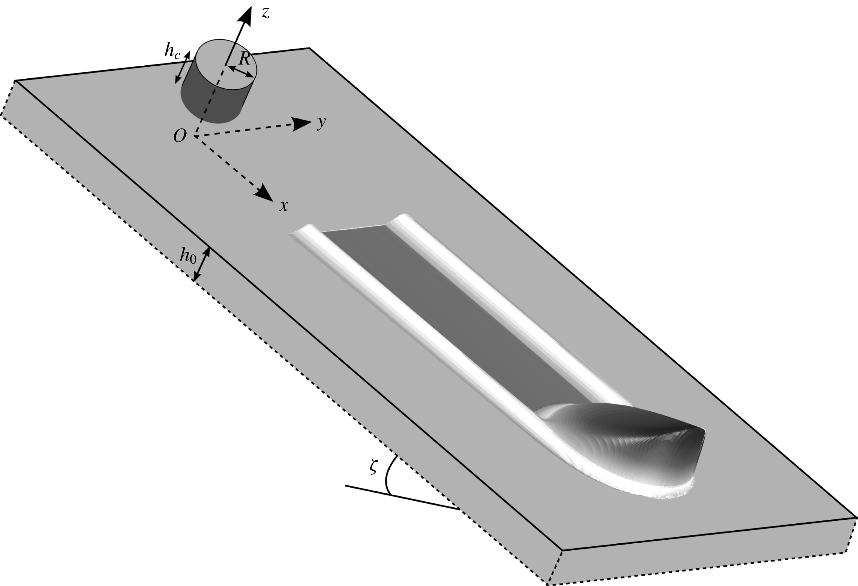
2.1 Experimental set-up and methods
To investigate the formation of three-dimensional erosion–deposition waves, small-scale experiments are performed to highlight some key qualitative features not previously described. The experimental set-up is shown in figure 3 and consists of a plane inclined at an angle
 $\unicode[STIX]{x1D701}$
to the horizontal, which is roughened by attaching a monolayer of spherical glass beads of diameter 750–
$\unicode[STIX]{x1D701}$
to the horizontal, which is roughened by attaching a monolayer of spherical glass beads of diameter 750–
 $1000~\unicode[STIX]{x03BC}\text{m}$
using double-sided sticky tape. A coordinate system
$1000~\unicode[STIX]{x03BC}\text{m}$
using double-sided sticky tape. A coordinate system
 $Oxyz$
is defined with the
$Oxyz$
is defined with the
 $x$
-axis pointing downslope, the
$x$
-axis pointing downslope, the
 $y$
-axis across the slope, with
$y$
-axis across the slope, with
 $y=0$
at the midpoint of the width of the plane, and the
$y=0$
at the midpoint of the width of the plane, and the
 $z$
-axis pointing normal to the rough plane at
$z$
-axis pointing normal to the rough plane at
 $z=0$
. The avalanche is assumed to have depth-averaged velocity components
$z=0$
. The avalanche is assumed to have depth-averaged velocity components
 $\bar{u}$
and
$\bar{u}$
and
 $\bar{v}$
in the downslope
$\bar{v}$
in the downslope
 $x$
and cross-slope
$x$
and cross-slope
 $y$
directions, respectively. The inclined plane is 1.5 m long by 0.5 m wide and has a hopper and gate mechanism at the top, which allows the bed to be coated with a static layer of 280–
$y$
directions, respectively. The inclined plane is 1.5 m long by 0.5 m wide and has a hopper and gate mechanism at the top, which allows the bed to be coated with a static layer of 280–
 $350~\unicode[STIX]{x03BC}\text{m}$
diameter carborundum particles prior to the start of the experiments. For a slope at an angle
$350~\unicode[STIX]{x03BC}\text{m}$
diameter carborundum particles prior to the start of the experiments. For a slope at an angle
 $\unicode[STIX]{x1D701}_{0}$
to the horizontal, the initial static layer is of thickness
$\unicode[STIX]{x1D701}_{0}$
to the horizontal, the initial static layer is of thickness
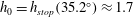
 $h_{0}=h_{stop}(\unicode[STIX]{x1D701}_{0})$
, i.e. the same thickness as that measured by Daerr & Douady (Reference Daerr and Douady1999) and Pouliquen (Reference Pouliquen1999a
). Once the grains have stopped the hysteresis of the friction law allows the chute to be inclined to a new angle
$h_{0}=h_{stop}(\unicode[STIX]{x1D701}_{0})$
, i.e. the same thickness as that measured by Daerr & Douady (Reference Daerr and Douady1999) and Pouliquen (Reference Pouliquen1999a
). Once the grains have stopped the hysteresis of the friction law allows the chute to be inclined to a new angle
 $\unicode[STIX]{x1D701}<\unicode[STIX]{x1D701}_{start}$
that is steeper than
$\unicode[STIX]{x1D701}<\unicode[STIX]{x1D701}_{start}$
that is steeper than
 $\unicode[STIX]{x1D701}_{0}=\unicode[STIX]{x1D701}_{stop}$
without the grains becoming mobile again.
$\unicode[STIX]{x1D701}_{0}=\unicode[STIX]{x1D701}_{stop}$
without the grains becoming mobile again.
A wooden plane with a layer of 750–
 $1000~\unicode[STIX]{x03BC}\text{m}$
spherical glass beads stuck to the surface is inclined at an angle
$1000~\unicode[STIX]{x03BC}\text{m}$
spherical glass beads stuck to the surface is inclined at an angle
 $\unicode[STIX]{x1D701}$
to the horizontal. A coordinate system
$\unicode[STIX]{x1D701}$
to the horizontal. A coordinate system
 $Oxyz$
is centred at the release point with the
$Oxyz$
is centred at the release point with the
 $x$
-axis pointing downslope, the
$x$
-axis pointing downslope, the
 $y$
-axis across the slope and the
$y$
-axis across the slope and the
 $z$
-axis is aligned with the upward pointing normal. The chute is prepared with a constant-depth layer of 280–
$z$
-axis is aligned with the upward pointing normal. The chute is prepared with a constant-depth layer of 280–
 $350~\unicode[STIX]{x03BC}\text{m}$
diameter carborundum particles of thickness
$350~\unicode[STIX]{x03BC}\text{m}$
diameter carborundum particles of thickness
 $h_{0}=h_{stop}(\unicode[STIX]{x1D701}_{0})$
and a finite volume of the same grains is released on top of this layer from a hollow cylinder of radius
$h_{0}=h_{stop}(\unicode[STIX]{x1D701}_{0})$
and a finite volume of the same grains is released on top of this layer from a hollow cylinder of radius
 $R=1.4$
cm and height
$R=1.4$
cm and height
 $h_{c}=1.6$
cm centred at the origin
$h_{c}=1.6$
cm centred at the origin
 $(x,y)=(0,0)$
. Note that the hysteresis of the basal friction allows the inclination angle
$(x,y)=(0,0)$
. Note that the hysteresis of the basal friction allows the inclination angle
 $\unicode[STIX]{x1D701}$
to be greater than the preparation angle
$\unicode[STIX]{x1D701}$
to be greater than the preparation angle
 $\unicode[STIX]{x1D701}_{0}$
of the constant-depth layer provided
$\unicode[STIX]{x1D701}_{0}$
of the constant-depth layer provided
 $\unicode[STIX]{x1D701}<\unicode[STIX]{x1D701}_{start}$
.
$\unicode[STIX]{x1D701}<\unicode[STIX]{x1D701}_{start}$
.
The release point is centred at
 $(x,y)=(0,0)$
, which is 80 cm from the end of the chute. A finite volume of 280–
$(x,y)=(0,0)$
, which is 80 cm from the end of the chute. A finite volume of 280–
 $350~\unicode[STIX]{x03BC}\text{m}$
carborundum particles is then placed on top of the static layer by filling a hollow cylinder of radius
$350~\unicode[STIX]{x03BC}\text{m}$
carborundum particles is then placed on top of the static layer by filling a hollow cylinder of radius
 $R=1.4$
cm and height
$R=1.4$
cm and height
 $h_{c}=1.6$
cm. The flow is released by raising the cylinder, which causes the particles inside to spread from the downslope edge, like a small inclined column collapse (Mangeney et al.
Reference Mangeney, Roche, Hungr, Mangold, Faccanoni and Lucas2010), before forming an avalanche that travels down the plane whilst eroding the stationary layer at the wavefront and depositing particles behind. Figure 2 shows an oblique view of one of these avalanches as it travels downslope. In the trail left behind the flowing avalanche there are small static levees and a shallow trough, made visible by illuminating obliquely from the downstream end of the chute.
$h_{c}=1.6$
cm. The flow is released by raising the cylinder, which causes the particles inside to spread from the downslope edge, like a small inclined column collapse (Mangeney et al.
Reference Mangeney, Roche, Hungr, Mangold, Faccanoni and Lucas2010), before forming an avalanche that travels down the plane whilst eroding the stationary layer at the wavefront and depositing particles behind. Figure 2 shows an oblique view of one of these avalanches as it travels downslope. In the trail left behind the flowing avalanche there are small static levees and a shallow trough, made visible by illuminating obliquely from the downstream end of the chute.
To capture some of the subtle features of the flow, a high-speed camera (Teledyne DALSA Genie HM1400) is used to photograph it from overhead at a rate of 100 f.p.s. with oblique illumination from the downstream end of the chute. A space–time plot is constructed by extracting the middle row of pixels (along
 $y=0$
) from each image and combining them into a single plot with elapsed time
$y=0$
) from each image and combining them into a single plot with elapsed time
 $\hat{t}$
along the abscissa and distance
$\hat{t}$
along the abscissa and distance
 $x$
along the ordinate. Note that elapsed time
$x$
along the ordinate. Note that elapsed time
 $\hat{t}$
is offset from the real time
$\hat{t}$
is offset from the real time
 $t$
by a different unknown amount for each set of images. In addition, a Micro-Epsilon scanCONTROL 2700-100 laser profile sensor is used to acquire thickness data aligned along the
$t$
by a different unknown amount for each set of images. In addition, a Micro-Epsilon scanCONTROL 2700-100 laser profile sensor is used to acquire thickness data aligned along the
 $y$
-axis at three different downstream positions
$y$
-axis at three different downstream positions
 $x_{L}=12$
cm,
$x_{L}=12$
cm,
 $x_{L}=30$
cm and
$x_{L}=30$
cm and
 $x_{L}=50$
cm. The laser line measures the distance of the bulk flow particles away from the sensor at a frequency of 100 Hz and to an accuracy of
$x_{L}=50$
cm. The laser line measures the distance of the bulk flow particles away from the sensor at a frequency of 100 Hz and to an accuracy of
 $\pm 0.2$
mm (approximately a grain diameter) by laser triangulation. The thickness profile
$\pm 0.2$
mm (approximately a grain diameter) by laser triangulation. The thickness profile
 $h$
of the avalanche in the
$h$
of the avalanche in the
 $z$
-direction can then be calculated along the laser line by measuring the distance between the sensor and the bed before it is coated with the static layer of carborundum particles. Space time contour plots of the thickness are then built up for each position
$z$
-direction can then be calculated along the laser line by measuring the distance between the sensor and the bed before it is coated with the static layer of carborundum particles. Space time contour plots of the thickness are then built up for each position
 $x_{L}$
, although the experiment has to be repeated for each location. Experiments were carried out for various slope inclination angles and static layer depths, and three qualitatively different behaviours were observed, which are described in greater detail in the following sections.
$x_{L}$
, although the experiment has to be repeated for each location. Experiments were carried out for various slope inclination angles and static layer depths, and three qualitatively different behaviours were observed, which are described in greater detail in the following sections.
A sequence of overhead photos at times (a)
 $\hat{t}=0.8$
, (b)
$\hat{t}=0.8$
, (b)
 $\hat{t}=1.4$
, (c)
$\hat{t}=1.4$
, (c)
 $\hat{t}=2.0$
, (d)
$\hat{t}=2.0$
, (d)
 $\hat{t}=2.6$
and (e)
$\hat{t}=2.6$
and (e)
 $\hat{t}=3.2$
s showing a finite mass release from a cylinder of radius
$\hat{t}=3.2$
s showing a finite mass release from a cylinder of radius
 $R=1.4$
cm and height
$R=1.4$
cm and height
 $h_{c}=1.6$
cm on top of a static erodible layer of thickness
$h_{c}=1.6$
cm on top of a static erodible layer of thickness
 $h_{0}\approx 2.2$
mm on a slope inclined at
$h_{0}\approx 2.2$
mm on a slope inclined at
 $\unicode[STIX]{x1D701}=35.2^{\circ }$
. These are used to construct the space–time plot (f) along the centre line
$\unicode[STIX]{x1D701}=35.2^{\circ }$
. These are used to construct the space–time plot (f) along the centre line
 $y=0$
. Vertical grey lines indicate stationary grains. The wavefront of the avalanche appears as a diagonal white line and indicates that the avalanche travels downslope at near constant speed before accelerating slightly near the end of the plane. A movie showing the time-dependent evolution is available in the online supplementary material (movie 1).
$y=0$
. Vertical grey lines indicate stationary grains. The wavefront of the avalanche appears as a diagonal white line and indicates that the avalanche travels downslope at near constant speed before accelerating slightly near the end of the plane. A movie showing the time-dependent evolution is available in the online supplementary material (movie 1).

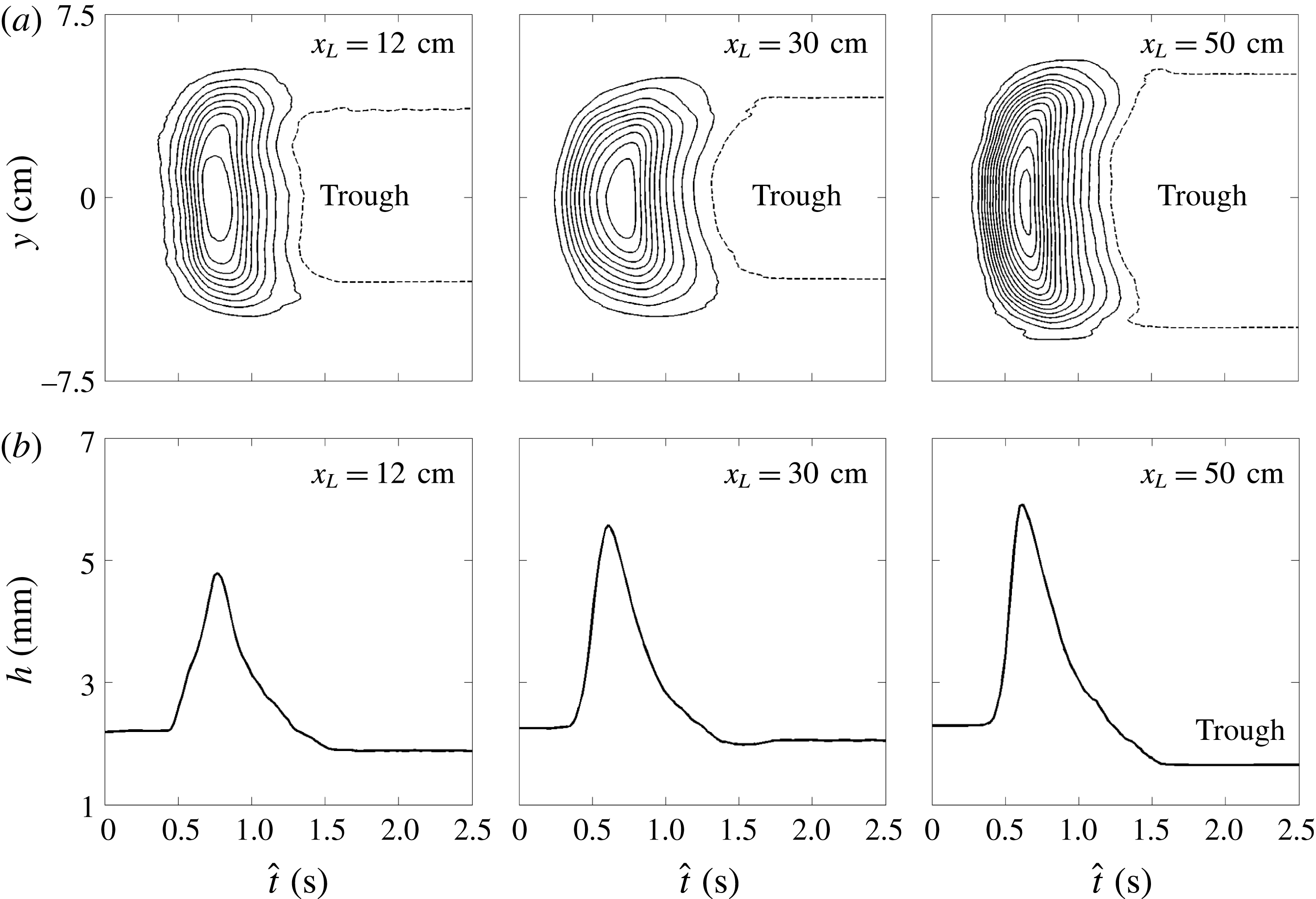
Measured avalanche thickness at three positions
 $x_{L}=12$
cm,
$x_{L}=12$
cm,
 $x_{L}=30$
cm and
$x_{L}=30$
cm and
 $x_{L}=50$
cm downslope of the finite mass release on a slope
$x_{L}=50$
cm downslope of the finite mass release on a slope
 $\unicode[STIX]{x1D701}=35.2^{\circ }$
with a deep layer of static erodible grains of thickness
$\unicode[STIX]{x1D701}=35.2^{\circ }$
with a deep layer of static erodible grains of thickness
 $h_{0}\approx 2.2$
mm, corresponding to
$h_{0}\approx 2.2$
mm, corresponding to
 $h_{stop}$
at
$h_{stop}$
at
 $\unicode[STIX]{x1D701}_{0}=34.4^{\circ }$
. The thickness is plotted as (a) contours of constant flow thickness
$\unicode[STIX]{x1D701}_{0}=34.4^{\circ }$
. The thickness is plotted as (a) contours of constant flow thickness
 $h$
in the
$h$
in the
 $(\hat{t},y)$
-plane, in increasing increments of 0.2 mm inwards (solid lines) from the trough contour at
$(\hat{t},y)$
-plane, in increasing increments of 0.2 mm inwards (solid lines) from the trough contour at
 $h=2.2$
mm (dashed line) and (b) flow thickness
$h=2.2$
mm (dashed line) and (b) flow thickness
 $h$
along the midpoint of the plane
$h$
along the midpoint of the plane
 $y=0$
versus elapsed time
$y=0$
versus elapsed time
 $\hat{t}$
. The avalanche grows in width and peak thickness as it travels downslope leaving a trough in its wake.
$\hat{t}$
. The avalanche grows in width and peak thickness as it travels downslope leaving a trough in its wake.
A sequence of overhead photos at times (a)
 $\hat{t}=1.3$
, (b)
$\hat{t}=1.3$
, (b)
 $\hat{t}=2.3$
, (c)
$\hat{t}=2.3$
, (c)
 $\hat{t}=3.3$
, (d)
$\hat{t}=3.3$
, (d)
 $\hat{t}=4.3$
and (e)
$\hat{t}=4.3$
and (e)
 $\hat{t}=5.3$
s showing a finite mass release from a cylinder of radius
$\hat{t}=5.3$
s showing a finite mass release from a cylinder of radius
 $R=1.4$
cm and height
$R=1.4$
cm and height
 $h_{c}=1.6$
cm on top of a static erodible layer of thickness
$h_{c}=1.6$
cm on top of a static erodible layer of thickness
 $h_{0}=h_{stop}(34.1^{\circ })\approx 2.5$
mm on a slope inclined at
$h_{0}=h_{stop}(34.1^{\circ })\approx 2.5$
mm on a slope inclined at
 $\unicode[STIX]{x1D701}=34.1^{\circ }$
. These are used to construct the space–time plot (f) along the centre line
$\unicode[STIX]{x1D701}=34.1^{\circ }$
. These are used to construct the space–time plot (f) along the centre line
 $y=0$
. Vertical grey lines indicate stationary grains and the wavefront appears as a brighter line. The avalanche travels downslope at approximately constant speed before decelerating and stopping abruptly. A movie showing the time-dependent evolution is available in the online supplementary material (movie 2).
$y=0$
. Vertical grey lines indicate stationary grains and the wavefront appears as a brighter line. The avalanche travels downslope at approximately constant speed before decelerating and stopping abruptly. A movie showing the time-dependent evolution is available in the online supplementary material (movie 2).

Measured avalanche thickness at three positions
 $x_{L}=12$
cm,
$x_{L}=12$
cm,
 $x_{L}=30$
cm and
$x_{L}=30$
cm and
 $x_{L}=50$
cm downslope of the finite mass release for a chute inclined at
$x_{L}=50$
cm downslope of the finite mass release for a chute inclined at
 $\unicode[STIX]{x1D701}=34.1^{\circ }$
that is covered with a static erodible layer of thickness
$\unicode[STIX]{x1D701}=34.1^{\circ }$
that is covered with a static erodible layer of thickness
 $h_{0}=h_{stop}(34.1^{\circ })\approx 2.5$
mm. The thickness is plotted as (a) contours of constant flow thickness
$h_{0}=h_{stop}(34.1^{\circ })\approx 2.5$
mm. The thickness is plotted as (a) contours of constant flow thickness
 $h$
in the
$h$
in the
 $(\hat{t},y)$
-plane, in increasing increments of 0.2 mm inwards (solid lines) from the outer contour at
$(\hat{t},y)$
-plane, in increasing increments of 0.2 mm inwards (solid lines) from the outer contour at
 $h=2.8$
mm (dashed line) and (b) flow thickness
$h=2.8$
mm (dashed line) and (b) flow thickness
 $h$
along the midpoint of the plane
$h$
along the midpoint of the plane
 $y=0$
versus elapsed time
$y=0$
versus elapsed time
 $\hat{t}$
. The avalanche decreases in width as it travels downslope, depositing an elevated channel behind it with levees along its flanks, before it finally comes to rest.
$\hat{t}$
. The avalanche decreases in width as it travels downslope, depositing an elevated channel behind it with levees along its flanks, before it finally comes to rest.
2.2 Growing avalanches
In order to generate an avalanche that has a net increase in mass as it propagates downslope the plane is first inclined at an angle of
 $\unicode[STIX]{x1D701}=34.4^{\circ }$
and the bed is coated with a static layer of carborundum that has a thickness
$\unicode[STIX]{x1D701}=34.4^{\circ }$
and the bed is coated with a static layer of carborundum that has a thickness
 $h_{0}=h_{stop}(34.4^{\circ })\approx 2.2$
mm. Without disturbing the grains in the static layer, the slope angle is then increased to a higher angle of
$h_{0}=h_{stop}(34.4^{\circ })\approx 2.2$
mm. Without disturbing the grains in the static layer, the slope angle is then increased to a higher angle of
 $\unicode[STIX]{x1D701}=35.2^{\circ }$
. The deposit layer then is thicker than the usual
$\unicode[STIX]{x1D701}=35.2^{\circ }$
. The deposit layer then is thicker than the usual
 $h_{stop}$
at
$h_{stop}$
at
 $35.2^{\circ }$
by virtue of the hysteresis in the friction law in the range
$35.2^{\circ }$
by virtue of the hysteresis in the friction law in the range
 $\unicode[STIX]{x1D701}\in [\unicode[STIX]{x1D701}_{stop},\unicode[STIX]{x1D701}_{start}]$
. The cylinder is held on top of the layer, filled with grains and the avalanche is then released.
$\unicode[STIX]{x1D701}\in [\unicode[STIX]{x1D701}_{stop},\unicode[STIX]{x1D701}_{start}]$
. The cylinder is held on top of the layer, filled with grains and the avalanche is then released.
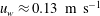
Overhead images of the avalanche on the inclined plane and a space–time plot constructed from them are shown in figure 4. There is also a movie of the flow in the online supplementary material available at https://doi.org/10.1017/jfm.2017.309 (movie 1). After the initial release the avalanche rapidly develops a sharp front that erodes material and a tail that decreases in height much more gently, and from which grains are continually being deposited. Overall there is net erosion and the avalanche grows in size, leaving behind it a trough formed from the previously mobilized grains, which is thinner than the initially prepared layer. The vertical grey lines on the space–time plot in figure 4(f) indicate stationary grains and the flow front appears as a strong line across the plot due to the oblique lighting from the downstream end of the chute. This indicates that the avalanche travels at a near constant wavespeed of
 $u_{w}\approx 0.26~\text{m}~\text{s}^{-1}$
although there is evidence of it beginning to slightly accelerate towards the end of the plane.
$u_{w}\approx 0.26~\text{m}~\text{s}^{-1}$
although there is evidence of it beginning to slightly accelerate towards the end of the plane.
Data from the laser profilometer are shown in figure 5 as (a) contours of thickness
 $h$
in the
$h$
in the
 $(\hat{t},y)$
-plane and (b) as thickness along the centre of the plane
$(\hat{t},y)$
-plane and (b) as thickness along the centre of the plane
 $y=0$
at each of the distances
$y=0$
at each of the distances
 $x_{L}$
. After the initial collapse the avalanche propagates downslope and both the width
$x_{L}$
. After the initial collapse the avalanche propagates downslope and both the width
 $W$
and the wave peak height
$W$
and the wave peak height
 $h_{w}$
continually increase to the end of the plane. The measured values are
$h_{w}$
continually increase to the end of the plane. The measured values are
 $W\approx 11$
cm,
$W\approx 11$
cm,
 $h_{w}\approx 5.6$
mm at
$h_{w}\approx 5.6$
mm at
 $x_{L}=30$
cm and
$x_{L}=30$
cm and
 $W\approx 14$
cm,
$W\approx 14$
cm,
 $h_{w}\approx 5.9$
mm at
$h_{w}\approx 5.9$
mm at
 $x_{L}=50$
cm (figure 5). Since the overall length is approximately the same there is a net increase in avalanche mass and a shallow trough forms behind the avalanche. The trough widens with downstream distance as shown in the overhead photos in figure 4(e), which makes it analogous to the ‘triangular avalanches’ first described by Daerr & Douady (Reference Daerr and Douady1999). The deposited layer depth in the trough, denoted by
$x_{L}=50$
cm (figure 5). Since the overall length is approximately the same there is a net increase in avalanche mass and a shallow trough forms behind the avalanche. The trough widens with downstream distance as shown in the overhead photos in figure 4(e), which makes it analogous to the ‘triangular avalanches’ first described by Daerr & Douady (Reference Daerr and Douady1999). The deposited layer depth in the trough, denoted by
 $h_{deposit}$
, continually decreases to a minimum value of
$h_{deposit}$
, continually decreases to a minimum value of
 $h_{deposit}\approx 1.7$
mm at
$h_{deposit}\approx 1.7$
mm at
 $x_{L}=50$
cm. This is close to the static layer thickness
$x_{L}=50$
cm. This is close to the static layer thickness
 $h_{stop}(35.2^{\circ })\approx 1.7$
mm.
$h_{stop}(35.2^{\circ })\approx 1.7$
mm.
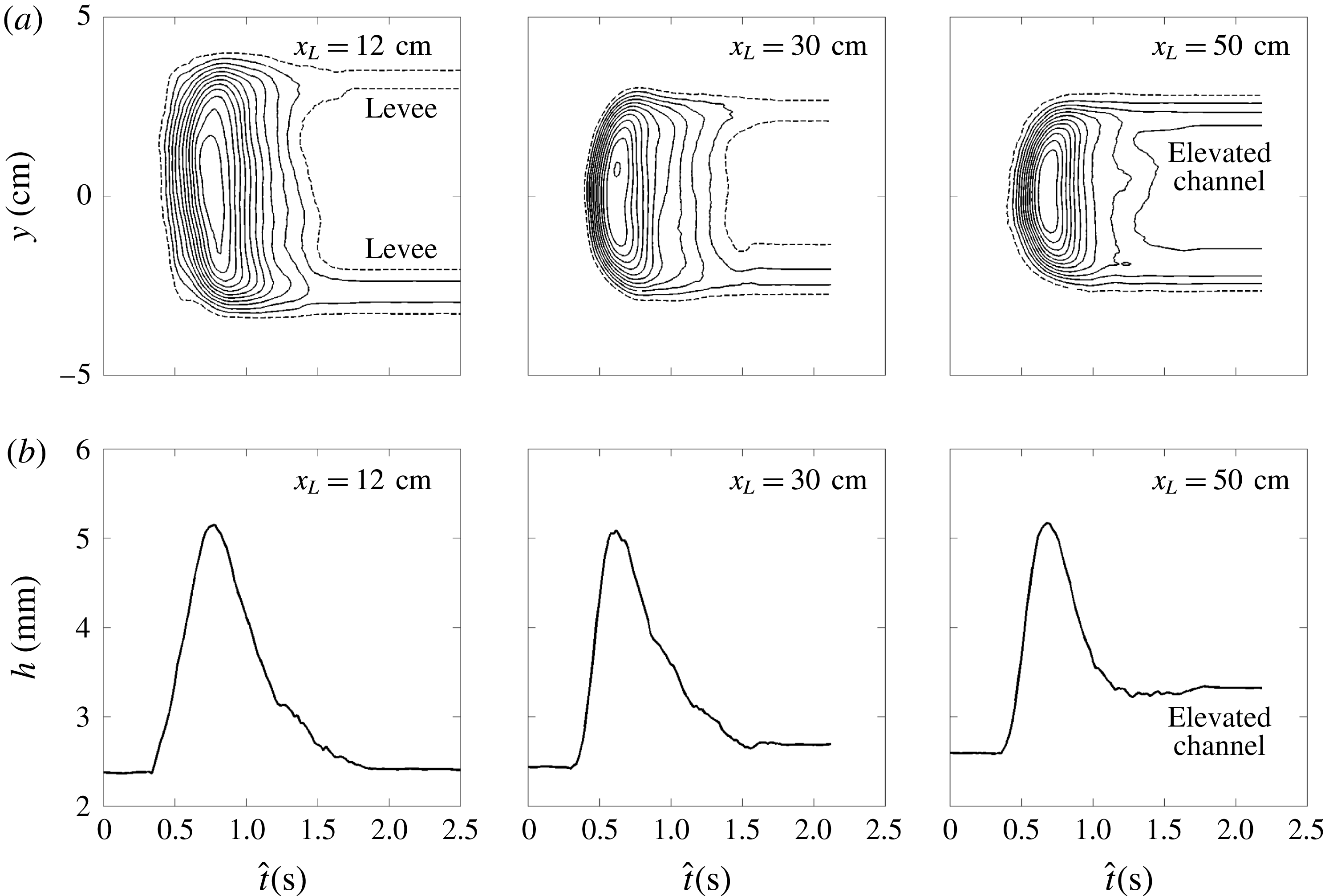
2.3 Decaying avalanches
Next the plane is inclined at an angle of
 $\unicode[STIX]{x1D701}=34.1^{\circ }$
to the horizontal and coated with a static layer of thickness
$\unicode[STIX]{x1D701}=34.1^{\circ }$
to the horizontal and coated with a static layer of thickness
 $h_{0}=h_{stop}(34.1^{\circ })\approx 2.5$
mm. A sequence of overhead images of the avalanche and a space–time plot constructed from them are shown in figure 6. A movie is also available in the online supplementary material (movie 2). It can be seen that after the initial release of grains the avalanche travels downslope for a short distance before it stops abruptly. The nearly straight diagonal line in the space–time plot between
$h_{0}=h_{stop}(34.1^{\circ })\approx 2.5$
mm. A sequence of overhead images of the avalanche and a space–time plot constructed from them are shown in figure 6. A movie is also available in the online supplementary material (movie 2). It can be seen that after the initial release of grains the avalanche travels downslope for a short distance before it stops abruptly. The nearly straight diagonal line in the space–time plot between
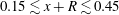 $0.15\lesssim x+R\lesssim 0.45$
m indicates that typical wavespeeds are
$0.15\lesssim x+R\lesssim 0.45$
m indicates that typical wavespeeds are
 $u_{w}\approx 0.13~\text{m}~\text{s}^{-1}$
and that there is a very rapid deceleration in the final stages before the avalanche abruptly comes to rest at
$u_{w}\approx 0.13~\text{m}~\text{s}^{-1}$
and that there is a very rapid deceleration in the final stages before the avalanche abruptly comes to rest at
 $x=55$
cm downslope. As the avalanche flows down the inclined plane it erodes mass at the front, but deposits far more mass behind it, to form an elevated channel that lies above the height of the undisturbed deposit and is flanked by levees on either side. To make this precise, figure 7, shows (a) thickness contours in the
$x=55$
cm downslope. As the avalanche flows down the inclined plane it erodes mass at the front, but deposits far more mass behind it, to form an elevated channel that lies above the height of the undisturbed deposit and is flanked by levees on either side. To make this precise, figure 7, shows (a) thickness contours in the
 $(\hat{t},y)$
-plane and (b) the thickness
$(\hat{t},y)$
-plane and (b) the thickness
 $h$
along the centre of the plane
$h$
along the centre of the plane
 $y=0$
at each of the
$y=0$
at each of the
 $x_{L}$
locations. The grains spread to a maximum width of
$x_{L}$
locations. The grains spread to a maximum width of
 $W\approx 8.5$
cm at
$W\approx 8.5$
cm at
 $x_{L}=12$
cm, before reducing to a width of
$x_{L}=12$
cm, before reducing to a width of
 $W\approx 5.5$
cm when the avalanche reaches
$W\approx 5.5$
cm when the avalanche reaches
 $x_{L}=50$
cm (figure 7
a). The narrowing of the deposit with increasing downstream distance can also be clearly seen in figure 6(e). The wave peak height
$x_{L}=50$
cm (figure 7
a). The narrowing of the deposit with increasing downstream distance can also be clearly seen in figure 6(e). The wave peak height
 $h_{w}\approx 5.1$
mm throughout the flow. However, the deposit thickness in the elevated channel increases significantly above the static layer thickness
$h_{w}\approx 5.1$
mm throughout the flow. However, the deposit thickness in the elevated channel increases significantly above the static layer thickness
 $h_{stop}\approx 2.5$
mm, to
$h_{stop}\approx 2.5$
mm, to
 $h_{deposit}\approx 2.7$
mm at
$h_{deposit}\approx 2.7$
mm at
 $x_{L}=30$
cm and
$x_{L}=30$
cm and
 $h_{deposit}\approx 3.3$
mm at
$h_{deposit}\approx 3.3$
mm at
 $x_{L}=50$
cm (figure 7
b). The deposit is able to remain static by virtue the hysteresis in the friction law (Daerr & Douady Reference Daerr and Douady1999; Pouliquen & Forterre Reference Pouliquen and Forterre2002) since
$x_{L}=50$
cm (figure 7
b). The deposit is able to remain static by virtue the hysteresis in the friction law (Daerr & Douady Reference Daerr and Douady1999; Pouliquen & Forterre Reference Pouliquen and Forterre2002) since
 $h_{stop}<h_{deposit}<h_{start}$
. The fact that the wavespeed
$h_{stop}<h_{deposit}<h_{start}$
. The fact that the wavespeed
 $u_{w}$
is almost constant during most of the flow may be related to the fact that the wave peak height is the same at each of the downstream locations
$u_{w}$
is almost constant during most of the flow may be related to the fact that the wave peak height is the same at each of the downstream locations
 $x_{L}$
(Razis et al.
Reference Razis, Edwards, Gray and van der Weele2014).
$x_{L}$
(Razis et al.
Reference Razis, Edwards, Gray and van der Weele2014).
2.4 Solitary steadily travelling avalanches
Finally, the plane is inclined at an angle of
 $\unicode[STIX]{x1D701}=35.2^{\circ }$
and the bed is coated with a static layer of thickness
$\unicode[STIX]{x1D701}=35.2^{\circ }$
and the bed is coated with a static layer of thickness
 $h_{0}=h_{stop}(35.2)\approx 1.6$
mm. A series of overhead images of the avalanche propagating down the plane and a space–time plot constructed from them are shown in figure 8. A movie is also available in the online supplementary material (movie 3). After the initial release the avalanche rapidly develops into a steadily travelling wave, so that by
$h_{0}=h_{stop}(35.2)\approx 1.6$
mm. A series of overhead images of the avalanche propagating down the plane and a space–time plot constructed from them are shown in figure 8. A movie is also available in the online supplementary material (movie 3). After the initial release the avalanche rapidly develops into a steadily travelling wave, so that by
 $\hat{x}=x+R\approx 15$
cm it remains at a constant width and has a near constant wavespeed of
$\hat{x}=x+R\approx 15$
cm it remains at a constant width and has a near constant wavespeed of
 $u_{w}\approx 0.20~\text{m}~\text{s}^{-1}$
for the remaining length of the experimental plane. This suggests that the frontal erosion and deposition at the base, sides and tail of the avalanche are in exact balance, i.e. it has developed into a steadily travelling solitary wave similar to the two-dimensional erosion–deposition waves observed by Edwards & Gray (Reference Edwards and Gray2015). In this case, however, the wave has a well defined three-dimensional crescentic shape and it leaves behind static levees and a trough incised below the height of the undisturbed deposit. This is precisely shown by the laser profilometer thickness data in figure 9. After the initial release from the cylinder, the grains spread to a maximum width of
$u_{w}\approx 0.20~\text{m}~\text{s}^{-1}$
for the remaining length of the experimental plane. This suggests that the frontal erosion and deposition at the base, sides and tail of the avalanche are in exact balance, i.e. it has developed into a steadily travelling solitary wave similar to the two-dimensional erosion–deposition waves observed by Edwards & Gray (Reference Edwards and Gray2015). In this case, however, the wave has a well defined three-dimensional crescentic shape and it leaves behind static levees and a trough incised below the height of the undisturbed deposit. This is precisely shown by the laser profilometer thickness data in figure 9. After the initial release from the cylinder, the grains spread to a maximum width of
 $W\approx 8.5$
cm, which is maintained as the avalanche travels downslope (figure 9
a). The wave peak height increases from the initial stages up to
$W\approx 8.5$
cm, which is maintained as the avalanche travels downslope (figure 9
a). The wave peak height increases from the initial stages up to
 $h_{w}\approx 4.3$
mm at
$h_{w}\approx 4.3$
mm at
 $x_{L}=30$
cm and afterwards remains nearly constant, as in the previous experiment. In this case however, the deposit layer in the avalanche trough also remains approximately constant at
$x_{L}=30$
cm and afterwards remains nearly constant, as in the previous experiment. In this case however, the deposit layer in the avalanche trough also remains approximately constant at
 $h_{deposit}\approx 1.5$
mm, which is, crucially, very slightly thinner than the static layer thickness,
$h_{deposit}\approx 1.5$
mm, which is, crucially, very slightly thinner than the static layer thickness,
 $h_{stop}\approx 1.7$
mm (figure 9
b). The deficit in grains in the trough is made up by the formation of very small static levees, which are slightly higher than the original erodible layer depth
$h_{stop}\approx 1.7$
mm (figure 9
b). The deficit in grains in the trough is made up by the formation of very small static levees, which are slightly higher than the original erodible layer depth
 $h_{0}$
as shown in figure 9(a). Since this flow is at the same angle as the growing avalanche, shown in figure 4, it is clear that it is possible to switch between growing, decaying and steady avalanches by changing
$h_{0}$
as shown in figure 9(a). Since this flow is at the same angle as the growing avalanche, shown in figure 4, it is clear that it is possible to switch between growing, decaying and steady avalanches by changing
 $h_{0}$
, at least for a certain range of slope angles.
$h_{0}$
, at least for a certain range of slope angles.
A sequence of overhead photos at times (a)
 $\hat{t}=0.9$
, (b)
$\hat{t}=0.9$
, (b)
 $\hat{t}=1.4$
, (c)
$\hat{t}=1.4$
, (c)
 $\hat{t}=1.9$
, (d)
$\hat{t}=1.9$
, (d)
 $\hat{t}=2.4$
and (e)
$\hat{t}=2.4$
and (e)
 $\hat{t}=2.9$
s showing a finite mass release from a cylinder of radius
$\hat{t}=2.9$
s showing a finite mass release from a cylinder of radius
 $R=1.4$
cm and height
$R=1.4$
cm and height
 $h_{c}=1.6$
cm on top of a static erodible layer of thickness
$h_{c}=1.6$
cm on top of a static erodible layer of thickness
 $h_{0}=h_{stop}(35.2^{\circ })\approx 1.7$
mm on a slope inclined at
$h_{0}=h_{stop}(35.2^{\circ })\approx 1.7$
mm on a slope inclined at
 $\unicode[STIX]{x1D701}=35.2^{\circ }$
. These are used to construct the space–time plot (f) along the centre line
$\unicode[STIX]{x1D701}=35.2^{\circ }$
. These are used to construct the space–time plot (f) along the centre line
 $y=0$
. Vertical grey lines indicate stationary grains and the wavefront appears as a brighter line. The avalanche travels downslope at approximately constant speed leaving small parallel lateral levees and a shallow trough in its wake. A movie showing the time-dependent evolution is available in the online supplementary material (movie 3).
$y=0$
. Vertical grey lines indicate stationary grains and the wavefront appears as a brighter line. The avalanche travels downslope at approximately constant speed leaving small parallel lateral levees and a shallow trough in its wake. A movie showing the time-dependent evolution is available in the online supplementary material (movie 3).

Measured avalanche thickness at three positions
 $x_{L}=12$
cm,
$x_{L}=12$
cm,
 $x_{L}=30$
cm and
$x_{L}=30$
cm and
 $x_{L}=50$
cm downslope of the finite mass release on a slope inclined at
$x_{L}=50$
cm downslope of the finite mass release on a slope inclined at
 $\unicode[STIX]{x1D701}=35.2^{\circ }$
that is initially covered with a static erodible layer of grains of thickness
$\unicode[STIX]{x1D701}=35.2^{\circ }$
that is initially covered with a static erodible layer of grains of thickness
 $h_{0}=h_{stop}(35.2^{\circ })\approx 1.7$
mm. The thickness is plotted as (a) contours of constant flow thickness
$h_{0}=h_{stop}(35.2^{\circ })\approx 1.7$
mm. The thickness is plotted as (a) contours of constant flow thickness
 $h$
in the
$h$
in the
 $(\hat{t},y)$
-plane, in increasing increments of 0.2 mm inwards (solid lines) from the outer contour at
$(\hat{t},y)$
-plane, in increasing increments of 0.2 mm inwards (solid lines) from the outer contour at
 $h=1.8$
mm (dashed line) and (b) flow thickness
$h=1.8$
mm (dashed line) and (b) flow thickness
 $h$
along the midpoint of the plane
$h$
along the midpoint of the plane
 $y=0$
versus elapsed time
$y=0$
versus elapsed time
 $\hat{t}$
. The avalanche adjusts to form a constant width channel with levees and an eroded trough behind it.
$\hat{t}$
. The avalanche adjusts to form a constant width channel with levees and an eroded trough behind it.
3 Measurements of the rough bed friction law
Pouliquen (Reference Pouliquen1999a
) performed laboratory experiments for flows of spherical glass beads on a rough chute and found an empirical friction law that was valid for steady uniform flows at various slope angles. This law was derived from a steady uniform flow rule that was later found by Forterre & Pouliquen (Reference Forterre and Pouliquen2003) to take a slightly different form for flows of sand on a rough chute. An extension of the Pouliquen (Reference Pouliquen1999a
) friction law was made by Pouliquen & Forterre (Reference Pouliquen and Forterre2002) to include flows outside of the dynamic regime, when the Froude number was lower than the minimum required for a steady uniform flow to be possible, down to
 $Fr=0$
for static material. This comprised a law that took a different form in each of these dynamic, static and intermediate regimes. They considered two critical slope inclination angles as functions of the flow thickness
$Fr=0$
for static material. This comprised a law that took a different form in each of these dynamic, static and intermediate regimes. They considered two critical slope inclination angles as functions of the flow thickness
 $h$
, namely
$h$
, namely
 $\unicode[STIX]{x1D701}_{stop}(h)$
and
$\unicode[STIX]{x1D701}_{stop}(h)$
and
 $\unicode[STIX]{x1D701}_{start}(h)$
, where
$\unicode[STIX]{x1D701}_{start}(h)$
, where
 $\unicode[STIX]{x1D701}_{stop}(h)$
is the slope angle at which a steady uniform flow leaves a deposit of thickness
$\unicode[STIX]{x1D701}_{stop}(h)$
is the slope angle at which a steady uniform flow leaves a deposit of thickness
 $h$
and
$h$
and
 $\unicode[STIX]{x1D701}_{start}(h)$
is the angle at which a layer of thickness
$\unicode[STIX]{x1D701}_{start}(h)$
is the angle at which a layer of thickness
 $h$
is mobilized. The thickness of a deposit left by a steady uniform flow at an inclination angle
$h$
is mobilized. The thickness of a deposit left by a steady uniform flow at an inclination angle
 $\unicode[STIX]{x1D701}$
is denoted by
$\unicode[STIX]{x1D701}$
is denoted by
 $h_{stop}(\unicode[STIX]{x1D701})$
, which is the inverse function of
$h_{stop}(\unicode[STIX]{x1D701})$
, which is the inverse function of
 $\unicode[STIX]{x1D701}_{stop}(h)$
, and the thickness of a static layer that is mobilised when the inclination is increased to an angle
$\unicode[STIX]{x1D701}_{stop}(h)$
, and the thickness of a static layer that is mobilised when the inclination is increased to an angle
 $\unicode[STIX]{x1D701}$
is denoted by
$\unicode[STIX]{x1D701}$
is denoted by
 $h_{start}(\unicode[STIX]{x1D701})$
, which is the inverse function of
$h_{start}(\unicode[STIX]{x1D701})$
, which is the inverse function of
 $\unicode[STIX]{x1D701}_{start}(h)$
.
$\unicode[STIX]{x1D701}_{start}(h)$
.
Critical angle curves
 $\unicode[STIX]{x1D701}_{stop}$
(solid line) and
$\unicode[STIX]{x1D701}_{stop}$
(solid line) and
 $\unicode[STIX]{x1D701}_{start}$
(dashed line), which are fits to experimental data (circles) of the respective forms in (3.1). The plot is annotated with arrows to show the progression between the curves as they are found experimentally, by increasing the slope angle to trigger avalanches that leave deposits of decreasing thickness.
$\unicode[STIX]{x1D701}_{start}$
(dashed line), which are fits to experimental data (circles) of the respective forms in (3.1). The plot is annotated with arrows to show the progression between the curves as they are found experimentally, by increasing the slope angle to trigger avalanches that leave deposits of decreasing thickness.

The procedures for determining the critical slope angles and the empirical steady uniform flow law have been repeated here for the experimental set-up described above, namely for a flow of 280–
 $350~\unicode[STIX]{x03BC}\text{m}$
carborundum particles on a rough bed of spherical glass beads. The critical slope angle curves,
$350~\unicode[STIX]{x03BC}\text{m}$
carborundum particles on a rough bed of spherical glass beads. The critical slope angle curves,
 $\unicode[STIX]{x1D701}_{stop}(h)$
and
$\unicode[STIX]{x1D701}_{stop}(h)$
and
 $\unicode[STIX]{x1D701}_{start}(h)$
are determined by fits to experimental data, which comprise measurements of the respective thicknesses,
$\unicode[STIX]{x1D701}_{start}(h)$
are determined by fits to experimental data, which comprise measurements of the respective thicknesses,
 $h_{stop}(\unicode[STIX]{x1D701})$
and
$h_{stop}(\unicode[STIX]{x1D701})$
and
 $h_{start}(\unicode[STIX]{x1D701})$
, at various angles
$h_{start}(\unicode[STIX]{x1D701})$
, at various angles
 $\unicode[STIX]{x1D701}$
with the laser profilometer. Following Pouliquen & Forterre (Reference Pouliquen and Forterre2002), the experimental fits take the functional form
$\unicode[STIX]{x1D701}$
with the laser profilometer. Following Pouliquen & Forterre (Reference Pouliquen and Forterre2002), the experimental fits take the functional form
 $$\begin{eqnarray}\tan \unicode[STIX]{x1D701}_{stop,start}=\tan \unicode[STIX]{x1D701}_{1,3}+\frac{\tan \unicode[STIX]{x1D701}_{2}-\tan \unicode[STIX]{x1D701}_{1}}{1+h/{\mathcal{L}}}.\end{eqnarray}$$
Henceforth, the critical thickness curves take the inverse functional form
 $$\begin{eqnarray}h_{stop,start}(\unicode[STIX]{x1D701})={\mathcal{L}}\left(\frac{\tan \unicode[STIX]{x1D701}_{2}-\tan \unicode[STIX]{x1D701}_{1}}{\tan \unicode[STIX]{x1D701}-\tan \unicode[STIX]{x1D701}_{1,3}}-1\right)={\mathcal{L}}\unicode[STIX]{x1D6FE}_{stop,start}(\unicode[STIX]{x1D701}),\end{eqnarray}$$
where
 $$\begin{eqnarray}\unicode[STIX]{x1D6FE}_{stop,start}(\unicode[STIX]{x1D701})=\frac{\tan \unicode[STIX]{x1D701}_{2}-\tan \unicode[STIX]{x1D701}_{1}}{\tan \unicode[STIX]{x1D701}-\tan \unicode[STIX]{x1D701}_{1,3}}-1.\end{eqnarray}$$
There is no steady-uniform flow for inclination angles
 $\unicode[STIX]{x1D701}<\unicode[STIX]{x1D701}_{1}$
, which is the asymptote of the curve
$\unicode[STIX]{x1D701}<\unicode[STIX]{x1D701}_{1}$
, which is the asymptote of the curve
 $\unicode[STIX]{x1D701}_{stop}(h)$
for large
$\unicode[STIX]{x1D701}_{stop}(h)$
for large
 $h$
, and the flow is accelerated for
$h$
, and the flow is accelerated for
 $\unicode[STIX]{x1D701}>\unicode[STIX]{x1D701}_{2}=\unicode[STIX]{x1D701}_{stop}(0)$
. The third critical angle
$\unicode[STIX]{x1D701}>\unicode[STIX]{x1D701}_{2}=\unicode[STIX]{x1D701}_{stop}(0)$
. The third critical angle
 $\unicode[STIX]{x1D701}_{3}$
is the asymptote of the curve
$\unicode[STIX]{x1D701}_{3}$
is the asymptote of the curve
 $\unicode[STIX]{x1D701}_{start}(h)$
for large
$\unicode[STIX]{x1D701}_{start}(h)$
for large
 $h$
. The parameter
$h$
. The parameter
 ${\mathcal{L}}$
(having the dimensions of a length) is the characteristic depth of flow over which a transition between the angles
${\mathcal{L}}$
(having the dimensions of a length) is the characteristic depth of flow over which a transition between the angles
 $\unicode[STIX]{x1D701}_{1}$
and
$\unicode[STIX]{x1D701}_{1}$
and
 $\unicode[STIX]{x1D701}_{2}$
occurs in the friction law and as such it is dependent on the properties of the grains and on the bed roughness. The fits of these parameters to the experimental data with the functions (3.1) are shown in figure 10. The values of these and all of the other previously obtained or yet to be introduced parameters, whose values remain fixed throughout this paper, are given in table 1.
$\unicode[STIX]{x1D701}_{2}$
occurs in the friction law and as such it is dependent on the properties of the grains and on the bed roughness. The fits of these parameters to the experimental data with the functions (3.1) are shown in figure 10. The values of these and all of the other previously obtained or yet to be introduced parameters, whose values remain fixed throughout this paper, are given in table 1.
Material properties kept constant throughout.
3.1 Dynamic regime
For steady uniform flows the empirical flow relation between the ratio of the flow thickness
 $h$
to
$h$
to
 $h_{stop}(\unicode[STIX]{x1D701})$
and the Froude number was found by Forterre & Pouliquen (Reference Forterre and Pouliquen2003) to be
$h_{stop}(\unicode[STIX]{x1D701})$
and the Froude number was found by Forterre & Pouliquen (Reference Forterre and Pouliquen2003) to be
 $$\begin{eqnarray}Fr=\frac{|\bar{\boldsymbol{u}}|}{\sqrt{hg\cos \unicode[STIX]{x1D701}}}=\unicode[STIX]{x1D6FD}\frac{h}{h_{stop}(\unicode[STIX]{x1D701})}-\unicode[STIX]{x1D6E4}.\end{eqnarray}$$
Measurements of the flow thickness are made with the laser profilometer, whilst the depth-averaged downslope velocity
 $\bar{u}$
, which is equal to
$\bar{u}$
, which is equal to
 $|\bar{\boldsymbol{u}}|$
, is determined by the speed of a front travelling down the plane from a space–time plot of overhead images (measured in the same way as the wavespeeds in § 2). Here the constants
$|\bar{\boldsymbol{u}}|$
, is determined by the speed of a front travelling down the plane from a space–time plot of overhead images (measured in the same way as the wavespeeds in § 2). Here the constants
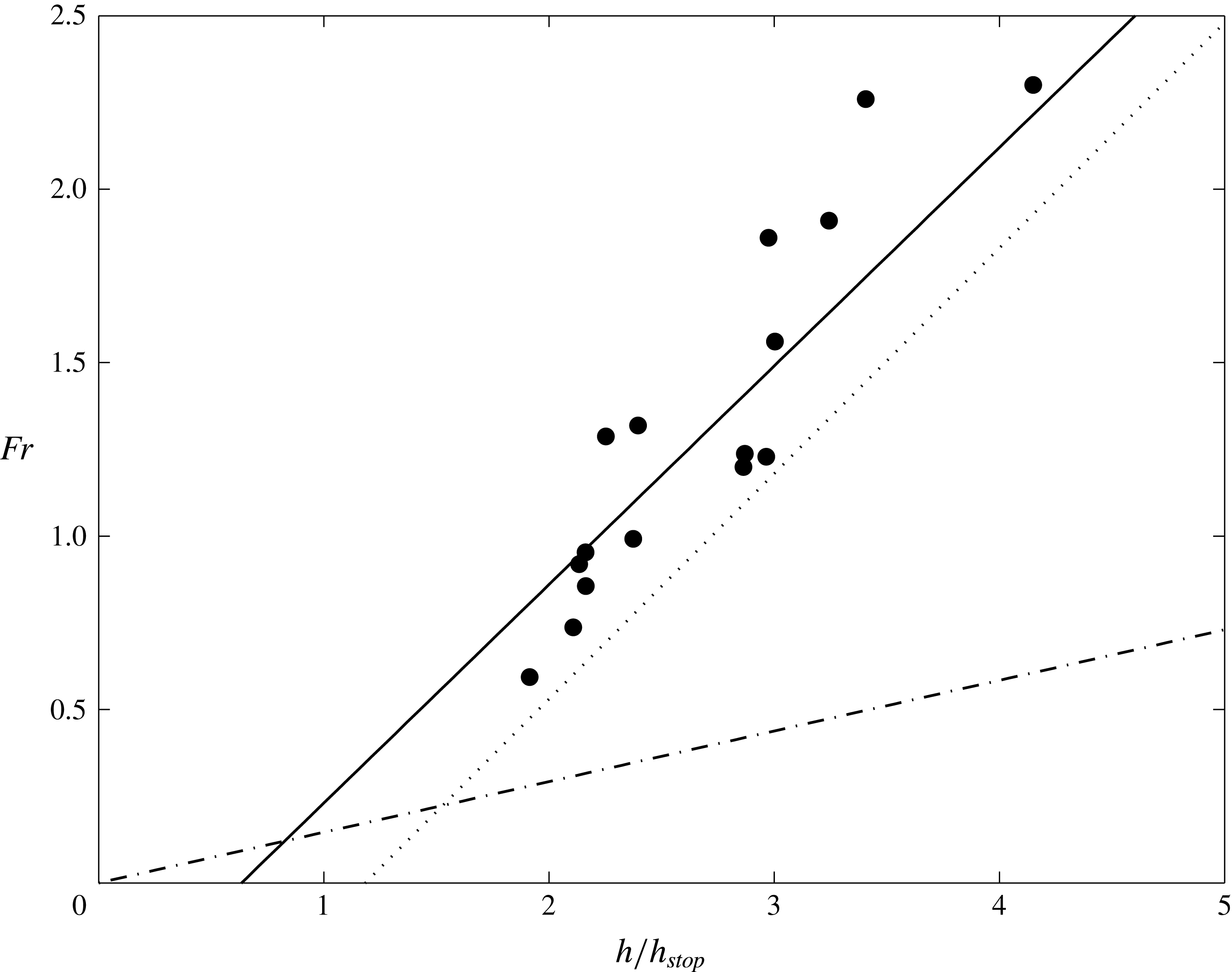
 $\unicode[STIX]{x1D6FD}=0.63$
and
$\unicode[STIX]{x1D6FD}=0.63$
and
 $\unicode[STIX]{x1D6E4}=0.40$
are best fits to the measured data, as shown in figure 11. The values of these constants were previously found to be
$\unicode[STIX]{x1D6E4}=0.40$
are best fits to the measured data, as shown in figure 11. The values of these constants were previously found to be
 $\unicode[STIX]{x1D6FD}=0.65$
and
$\unicode[STIX]{x1D6FD}=0.65$
and
 $\unicode[STIX]{x1D6E4}=0.77$
for flows of sand on a rough bed of the same material (Forterre & Pouliquen Reference Forterre and Pouliquen2003) and
$\unicode[STIX]{x1D6E4}=0.77$
for flows of sand on a rough bed of the same material (Forterre & Pouliquen Reference Forterre and Pouliquen2003) and
 $\unicode[STIX]{x1D6FD}=0.136/\sqrt{\cos \unicode[STIX]{x1D701}}$
and
$\unicode[STIX]{x1D6FD}=0.136/\sqrt{\cos \unicode[STIX]{x1D701}}$
and
 $\unicode[STIX]{x1D6E4}=0$
for flows of spherical glass beads on a rough bed of the same material (Pouliquen Reference Pouliquen1999a
).
$\unicode[STIX]{x1D6E4}=0$
for flows of spherical glass beads on a rough bed of the same material (Pouliquen Reference Pouliquen1999a
).
Measurements of the Froude number
 $Fr=|\bar{\boldsymbol{u}}|/\sqrt{gh\cos \unicode[STIX]{x1D701}}$
for steady uniform flow at various slope inclination angles
$Fr=|\bar{\boldsymbol{u}}|/\sqrt{gh\cos \unicode[STIX]{x1D701}}$
for steady uniform flow at various slope inclination angles
 $\unicode[STIX]{x1D701}$
, as a function of the ratio of the flow thickness
$\unicode[STIX]{x1D701}$
, as a function of the ratio of the flow thickness
 $h$
to the critical thickness
$h$
to the critical thickness
 $h_{stop}$
(black filled circles). The best fit to the data (solid line) of the form given in equation (3.4) is with
$h_{stop}$
(black filled circles). The best fit to the data (solid line) of the form given in equation (3.4) is with
 $\unicode[STIX]{x1D6FD}=0.63$
and
$\unicode[STIX]{x1D6FD}=0.63$
and
 $\unicode[STIX]{x1D6E4}=0.40$
. This is compared with the best fits to experiments with sand (Forterre & Pouliquen Reference Forterre and Pouliquen2003, dotted line), for which
$\unicode[STIX]{x1D6E4}=0.40$
. This is compared with the best fits to experiments with sand (Forterre & Pouliquen Reference Forterre and Pouliquen2003, dotted line), for which
 $\unicode[STIX]{x1D6FD}=0.65$
and
$\unicode[STIX]{x1D6FD}=0.65$
and
 $\unicode[STIX]{x1D6E4}=0.77$
, and with glass beads (Pouliquen Reference Pouliquen1999a
, dash-dotted line), for which
$\unicode[STIX]{x1D6E4}=0.77$
, and with glass beads (Pouliquen Reference Pouliquen1999a
, dash-dotted line), for which
 $\unicode[STIX]{x1D6FD}=0.136/\sqrt{\cos \unicode[STIX]{x1D701}}$
and
$\unicode[STIX]{x1D6FD}=0.136/\sqrt{\cos \unicode[STIX]{x1D701}}$
and
 $\unicode[STIX]{x1D6E4}=0$
.
$\unicode[STIX]{x1D6E4}=0$
.
With the critical flow thickness functions (3.1) and empirical flow rule (3.4) known, a friction law for the dynamic regime can now be determined. In a steady uniform flow there is a balance between gravity and the shear stress at the bed, which implies that the force balance may be written as (Pouliquen Reference Pouliquen1999a )
 $$\begin{eqnarray}\unicode[STIX]{x1D707}=\tan \unicode[STIX]{x1D701}.\end{eqnarray}$$
By defining the tangent of the critical stopping angle as
 $$\begin{eqnarray}\unicode[STIX]{x1D707}_{stop}(h)=\tan (\unicode[STIX]{x1D701}_{stop}(h)),\end{eqnarray}$$
the friction coefficient for the static layer is found through the steady uniform flow relation (3.5) and the empirical law (3.4) to be
 $$\begin{eqnarray}\unicode[STIX]{x1D707}=\tan \unicode[STIX]{x1D701}=\tan (\unicode[STIX]{x1D701}_{stop}(h_{stop}(\unicode[STIX]{x1D701})))=\unicode[STIX]{x1D707}_{stop}(h_{stop}(\unicode[STIX]{x1D701}))=\unicode[STIX]{x1D707}_{stop}(h\unicode[STIX]{x1D6FD}/(Fr+\unicode[STIX]{x1D6E4})).\end{eqnarray}$$
However the empirical law (3.4) and therefore the friction law (3.7) are only valid for flows in the dynamic regime, where steady uniform flows are possible. According to Pouliquen & Forterre (Reference Pouliquen and Forterre2002), a flow is in the dynamic regime if
 $h\geqslant h_{stop}(\unicode[STIX]{x1D701})$
, which is equivalent to
$h\geqslant h_{stop}(\unicode[STIX]{x1D701})$
, which is equivalent to
 $Fr\geqslant \unicode[STIX]{x1D6FD}$
in the case of glass beads, since the Froude number offset
$Fr\geqslant \unicode[STIX]{x1D6FD}$
in the case of glass beads, since the Froude number offset
 $\unicode[STIX]{x1D6E4}=0$
. For different granular materials, such as sand and the carborundum particles used here, which have higher values of
$\unicode[STIX]{x1D6E4}=0$
. For different granular materials, such as sand and the carborundum particles used here, which have higher values of
 $\unicode[STIX]{x1D6FD}$
, the transition between the dynamic and intermediate regimes is more complicated. Edwards & Gray (Reference Edwards and Gray2015) found that allowing a dynamic regime for
$\unicode[STIX]{x1D6FD}$
, the transition between the dynamic and intermediate regimes is more complicated. Edwards & Gray (Reference Edwards and Gray2015) found that allowing a dynamic regime for
 $h\geqslant h_{stop}(\unicode[STIX]{x1D701})$
in the same way as for glass beads, with
$h\geqslant h_{stop}(\unicode[STIX]{x1D701})$
in the same way as for glass beads, with
 $\unicode[STIX]{x1D6FD}=0.65$
and
$\unicode[STIX]{x1D6FD}=0.65$
and
 $\unicode[STIX]{x1D6E4}=0$
, leads to the formation of erosion–deposition waves that deposit grains in the wave troughs with a layer of thickness
$\unicode[STIX]{x1D6E4}=0$
, leads to the formation of erosion–deposition waves that deposit grains in the wave troughs with a layer of thickness
 $h_{deposit}$
that is significantly lower than
$h_{deposit}$
that is significantly lower than
 $h_{stop}(\unicode[STIX]{x1D701})$
. This implies that for a steady uniform flow to leave a layer of thickness
$h_{stop}(\unicode[STIX]{x1D701})$
. This implies that for a steady uniform flow to leave a layer of thickness
 $h_{stop}$
the transition between dynamic and intermediate friction regimes must occur at higher Froude number. Furthermore, for materials such as sand, where
$h_{stop}$
the transition between dynamic and intermediate friction regimes must occur at higher Froude number. Furthermore, for materials such as sand, where
 $\unicode[STIX]{x1D6FD}<\unicode[STIX]{x1D6E4}$
, the minimum Froude number for the transition to the intermediate regime, i.e.
$\unicode[STIX]{x1D6FD}<\unicode[STIX]{x1D6E4}$
, the minimum Froude number for the transition to the intermediate regime, i.e.
 $Fr=\unicode[STIX]{x1D6FD}-\unicode[STIX]{x1D6E4}$
by (3.4), is negative, implying that all flows can only be in the dynamic regime. To overcome these problems, a friction law transition point
$Fr=\unicode[STIX]{x1D6FD}-\unicode[STIX]{x1D6E4}$
by (3.4), is negative, implying that all flows can only be in the dynamic regime. To overcome these problems, a friction law transition point
 $h_{\ast }(\unicode[STIX]{x1D701})$
is introduced at a thickness between
$h_{\ast }(\unicode[STIX]{x1D701})$
is introduced at a thickness between
 $h_{stop}(\unicode[STIX]{x1D701})$
and
$h_{stop}(\unicode[STIX]{x1D701})$
and
 $h_{start}(\unicode[STIX]{x1D701})$
. This transition thickness is defined as
$h_{start}(\unicode[STIX]{x1D701})$
. This transition thickness is defined as
 $$\begin{eqnarray}h_{\ast }(\unicode[STIX]{x1D701})=(1-a)h_{stop}(\unicode[STIX]{x1D701})+ah_{start}(\unicode[STIX]{x1D701}),\end{eqnarray}$$
where
 $0\leqslant a\leqslant 1$
is a parameter whose value is chosen (
$0\leqslant a\leqslant 1$
is a parameter whose value is chosen (
 $a=0.5$
here) such that numerical simulations of the
$a=0.5$
here) such that numerical simulations of the
 $h_{stop}$
experimental measurement procedure correctly produce deposit layers with thickness
$h_{stop}$
experimental measurement procedure correctly produce deposit layers with thickness
 $h_{deposit}\approx h_{stop}$
. Changing the value of
$h_{deposit}\approx h_{stop}$
. Changing the value of
 $a$
does not qualitatively change the possible behaviours, but it changes
$a$
does not qualitatively change the possible behaviours, but it changes
 $h_{\ast }$
and therefore the flow thickness at which the transition between regimes occurs. Defining
$h_{\ast }$
and therefore the flow thickness at which the transition between regimes occurs. Defining
 $\unicode[STIX]{x1D6FD}_{\ast }$
to be the Froude number at
$\unicode[STIX]{x1D6FD}_{\ast }$
to be the Froude number at
 $h=h_{\ast }$
, and substituting the flow rule (3.4) into (3.8) gives the transition Froude number between the dynamic and intermediate regimes as
$h=h_{\ast }$
, and substituting the flow rule (3.4) into (3.8) gives the transition Froude number between the dynamic and intermediate regimes as
 $$\begin{eqnarray}\unicode[STIX]{x1D6FD}_{\ast }(\unicode[STIX]{x1D701})=\unicode[STIX]{x1D6FD}\left(1-a+a\frac{h_{start}(\unicode[STIX]{x1D701})}{h_{stop}(\unicode[STIX]{x1D701})}\right)-\unicode[STIX]{x1D6E4}.\end{eqnarray}$$
Note that the existence of the offset
 $\unicode[STIX]{x1D6E4}$
formally breaks the arguments based on the Bagnold flow profile that led to the creation of the
$\unicode[STIX]{x1D6E4}$
formally breaks the arguments based on the Bagnold flow profile that led to the creation of the
 $\unicode[STIX]{x1D707}(I)$
-rheology (GDR-MiDi 2004; Jop, Forterre & Pouliquen Reference Jop, Forterre and Pouliquen2005; Jop et al.
Reference Jop, Forterre and Pouliquen2006), since the scaling
$\unicode[STIX]{x1D707}(I)$
-rheology (GDR-MiDi 2004; Jop, Forterre & Pouliquen Reference Jop, Forterre and Pouliquen2005; Jop et al.
Reference Jop, Forterre and Pouliquen2006), since the scaling
 $h\unicode[STIX]{x1D6FD}/{\mathcal{L}}Fr=I_{0}/I$
, that allows the empirical friction law to be written as a function of the inertial number
$h\unicode[STIX]{x1D6FD}/{\mathcal{L}}Fr=I_{0}/I$
, that allows the empirical friction law to be written as a function of the inertial number
 $I$
and constant
$I$
and constant
 $I_{0}$
, is no longer valid for a flow rule of the form in (3.4). Nevertheless the offset in the friction law will be used in conjunction with the depth-averaged
$I_{0}$
, is no longer valid for a flow rule of the form in (3.4). Nevertheless the offset in the friction law will be used in conjunction with the depth-averaged
 $\unicode[STIX]{x1D707}(I)$
-rheology (Gray & Edwards Reference Gray and Edwards2014) in this paper. This is justified by the fact that for shallow flows the additional depth-averaged viscous term, where some modification may be necessary, is already much smaller than the leading-order terms in the downslope momentum balance.
$\unicode[STIX]{x1D707}(I)$
-rheology (Gray & Edwards Reference Gray and Edwards2014) in this paper. This is justified by the fact that for shallow flows the additional depth-averaged viscous term, where some modification may be necessary, is already much smaller than the leading-order terms in the downslope momentum balance.
3.2 Static regime
Defining the tangent of the critical starting angle as
 $$\begin{eqnarray}\unicode[STIX]{x1D707}_{start}(h)=\tan (\unicode[STIX]{x1D701}_{start}(h)),\end{eqnarray}$$
Pouliquen & Forterre (Reference Pouliquen and Forterre2002) showed that a knowledge of the functions
 $\unicode[STIX]{x1D707}_{stop}(h)$
and
$\unicode[STIX]{x1D707}_{stop}(h)$
and
 $\unicode[STIX]{x1D707}_{start}(h)$
is sufficient to define an empirical friction law for the whole range of possible flow thicknesses and Froude numbers. For
$\unicode[STIX]{x1D707}_{start}(h)$
is sufficient to define an empirical friction law for the whole range of possible flow thicknesses and Froude numbers. For
 $Fr=0$
the maximum static friction that can be attained occurs at
$Fr=0$
the maximum static friction that can be attained occurs at
 $\unicode[STIX]{x1D701}_{start}$
, where the friction coefficient
$\unicode[STIX]{x1D701}_{start}$
, where the friction coefficient
 $$\begin{eqnarray}\unicode[STIX]{x1D707}(h,0)=\tan (\unicode[STIX]{x1D701}_{start}(h))=\unicode[STIX]{x1D707}_{start}(h).\end{eqnarray}$$
In general, the static friction may lie below
 $\unicode[STIX]{x1D707}_{start}$
and simply balance the forces in order to prevent motion. For both the inviscid and depth-averaged
$\unicode[STIX]{x1D707}_{start}$
and simply balance the forces in order to prevent motion. For both the inviscid and depth-averaged
 $\unicode[STIX]{x1D707}(I)$
-rheology this is just a balance between effective basal friction, gravity pulling it down the slope and pressure gradients. It follows that
$\unicode[STIX]{x1D707}(I)$
-rheology this is just a balance between effective basal friction, gravity pulling it down the slope and pressure gradients. It follows that
 $\unicode[STIX]{x1D707}=|\text{tan}\,\unicode[STIX]{x1D701}\boldsymbol{i}-\unicode[STIX]{x1D735}h|$
, where
$\unicode[STIX]{x1D707}=|\text{tan}\,\unicode[STIX]{x1D701}\boldsymbol{i}-\unicode[STIX]{x1D735}h|$
, where
 $\boldsymbol{i}$
is the unit vector in the
$\boldsymbol{i}$
is the unit vector in the
 $x$
-direction.
$x$
-direction.
3.3 Intermediate regime
In the intermediate friction regime when
 $0<Fr<\unicode[STIX]{x1D6FD}_{\ast }$
, the friction coefficient
$0<Fr<\unicode[STIX]{x1D6FD}_{\ast }$
, the friction coefficient
 $\unicode[STIX]{x1D707}$
is given by a power law extrapolation between the friction laws in the static and dynamic friction regimes as
$\unicode[STIX]{x1D707}$
is given by a power law extrapolation between the friction laws in the static and dynamic friction regimes as
 $$\begin{eqnarray}\unicode[STIX]{x1D707}(h,Fr)=\left(\frac{Fr}{\unicode[STIX]{x1D6FD}_{\ast }}\right)^{\unicode[STIX]{x1D705}}(\unicode[STIX]{x1D707}_{stop}(h\unicode[STIX]{x1D6FD}/(\unicode[STIX]{x1D6FD}_{\ast }+\unicode[STIX]{x1D6E4}))-\unicode[STIX]{x1D707}_{start}(h))+\unicode[STIX]{x1D707}_{start}(h).\end{eqnarray}$$
The power of the extrapolation chosen by Pouliquen & Forterre (Reference Pouliquen and Forterre2002) was
 $\unicode[STIX]{x1D705}=10^{-3}$
, in order to give a rapid decrease of the friction coefficient close to
$\unicode[STIX]{x1D705}=10^{-3}$
, in order to give a rapid decrease of the friction coefficient close to
 $Fr=0$
. They found their results were insensitive to changes in
$Fr=0$
. They found their results were insensitive to changes in
 $\unicode[STIX]{x1D705}$
up to a value of
$\unicode[STIX]{x1D705}$
up to a value of
 $10^{-2}$
. Both of these values are extreme. As a result the decrease in friction from the static value is concentrated in a narrow boundary layer that lies close to
$10^{-2}$
. Both of these values are extreme. As a result the decrease in friction from the static value is concentrated in a narrow boundary layer that lies close to
 $Fr=0$
, and for much of the range the friction coefficient is essentially constant. In fact, these values of
$Fr=0$
, and for much of the range the friction coefficient is essentially constant. In fact, these values of
 $\unicode[STIX]{x1D705}$
are so extreme, that, to the accuracy of machine precision, the boundary layer is essentially invisible in numerical simulations. This may explain why Pouliquen & Forterre (Reference Pouliquen and Forterre2002) found that when they simulated a finite mass release on an erodible layer it had difficulty coming to rest, and ran out considerably further than in experiments. For the simulations presented here a value of
$\unicode[STIX]{x1D705}$
are so extreme, that, to the accuracy of machine precision, the boundary layer is essentially invisible in numerical simulations. This may explain why Pouliquen & Forterre (Reference Pouliquen and Forterre2002) found that when they simulated a finite mass release on an erodible layer it had difficulty coming to rest, and ran out considerably further than in experiments. For the simulations presented here a value of
 $\unicode[STIX]{x1D705}=1$
is used instead. This gives stationary material in the hysteretic region of parameter space much greater stability to small disturbances, as well as slowly moving material, above
$\unicode[STIX]{x1D705}=1$
is used instead. This gives stationary material in the hysteretic region of parameter space much greater stability to small disturbances, as well as slowly moving material, above
 $h_{stop}$
, a greater propensity to come to rest. In general, the value of
$h_{stop}$
, a greater propensity to come to rest. In general, the value of
 $\unicode[STIX]{x1D705}$
should be at least of order
$\unicode[STIX]{x1D705}$
should be at least of order
 $10^{-1}$
to prevent static layers that are thinner than
$10^{-1}$
to prevent static layers that are thinner than
 $h_{start}$
from moving without being disturbed and no greater than order 1, to allow them to flow if forced with the steady uniform flow velocity.
$h_{start}$
from moving without being disturbed and no greater than order 1, to allow them to flow if forced with the steady uniform flow velocity.
3.4 Friction coefficient
The forms of the functions
 $\unicode[STIX]{x1D707}_{stop}$
and
$\unicode[STIX]{x1D707}_{stop}$
and
 $\unicode[STIX]{x1D707}_{start}$
are found through the definitions (3.6) and (3.10) and the experimental fits (3.1) to be
$\unicode[STIX]{x1D707}_{start}$
are found through the definitions (3.6) and (3.10) and the experimental fits (3.1) to be
 $$\begin{eqnarray}\unicode[STIX]{x1D707}_{stop}(h\unicode[STIX]{x1D6FD}/(Fr+\unicode[STIX]{x1D6E4}))=\tan \unicode[STIX]{x1D701}_{1}+\frac{\tan \unicode[STIX]{x1D701}_{2}-\tan \unicode[STIX]{x1D701}_{1}}{1+h\unicode[STIX]{x1D6FD}/{\mathcal{L}}(Fr+\unicode[STIX]{x1D6E4})}\end{eqnarray}$$
and
 $$\begin{eqnarray}\unicode[STIX]{x1D707}_{start}(h)=\tan \unicode[STIX]{x1D701}_{3}+\frac{\tan \unicode[STIX]{x1D701}_{2}-\tan \unicode[STIX]{x1D701}_{1}}{1+h/{\mathcal{L}}},\end{eqnarray}$$
where the form of (3.13) has been modified from that of Pouliquen & Forterre (Reference Pouliquen and Forterre2002) in order to account for the offset
 $\unicode[STIX]{x1D6E4}$
.
$\unicode[STIX]{x1D6E4}$
.
In summary, the friction coefficient can be written in each of the three flow regimes, which are referred to as dynamic
 $(Fr\geqslant \unicode[STIX]{x1D6FD}_{\ast })$
, intermediate
$(Fr\geqslant \unicode[STIX]{x1D6FD}_{\ast })$
, intermediate
 $(0<Fr\leqslant \unicode[STIX]{x1D6FD}_{\ast })$
and static
$(0<Fr\leqslant \unicode[STIX]{x1D6FD}_{\ast })$
and static
 $(Fr=0)$
regimes, respectively, as
$(Fr=0)$
regimes, respectively, as
 $$\begin{eqnarray}\unicode[STIX]{x1D707}(h,Fr)=\left\{\begin{array}{@{}ll@{}}\displaystyle \unicode[STIX]{x1D707}_{1}+\frac{\unicode[STIX]{x1D707}_{2}-\unicode[STIX]{x1D707}_{1}}{1+h\unicode[STIX]{x1D6FD}/{\mathcal{L}}(Fr+\unicode[STIX]{x1D6E4})},\quad & Fr\geqslant \unicode[STIX]{x1D6FD}_{\ast },\\ \displaystyle \left(\frac{Fr}{\unicode[STIX]{x1D6FD}_{\ast }}\right)^{\unicode[STIX]{x1D705}}\left(\unicode[STIX]{x1D707}_{1}+\frac{\unicode[STIX]{x1D707}_{2}-\unicode[STIX]{x1D707}_{1}}{1+h\unicode[STIX]{x1D6FD}/{\mathcal{L}}(\unicode[STIX]{x1D6FD}_{\ast }+\unicode[STIX]{x1D6E4})}-\unicode[STIX]{x1D707}_{3}-\frac{\unicode[STIX]{x1D707}_{2}-\unicode[STIX]{x1D707}_{1}}{1+h/{\mathcal{L}}}\right)\quad & \\ \quad \displaystyle +\,\unicode[STIX]{x1D707}_{3}+\frac{\unicode[STIX]{x1D707}_{2}-\unicode[STIX]{x1D707}_{1}}{1+h/{\mathcal{L}}},\quad & 0<Fr\leqslant \unicode[STIX]{x1D6FD}_{\ast },\\ \displaystyle \text{min}\left(\unicode[STIX]{x1D707}_{3}+\frac{\unicode[STIX]{x1D707}_{2}-\unicode[STIX]{x1D707}_{1}}{1+h/{\mathcal{L}}},|\text{tan}\,\unicode[STIX]{x1D701}\boldsymbol{i}-\unicode[STIX]{x1D735}h|\right),\quad & Fr=0,\end{array}\right.\end{eqnarray}$$
where
 $\unicode[STIX]{x1D707}_{1}=\tan \unicode[STIX]{x1D701}_{1}$
,
$\unicode[STIX]{x1D707}_{1}=\tan \unicode[STIX]{x1D701}_{1}$
,
 $\unicode[STIX]{x1D707}_{2}=\tan \unicode[STIX]{x1D701}_{2}$
and
$\unicode[STIX]{x1D707}_{2}=\tan \unicode[STIX]{x1D701}_{2}$
and
 $\unicode[STIX]{x1D707}_{3}=\tan \unicode[STIX]{x1D701}_{3}$
are the tangents of the critical angles,
$\unicode[STIX]{x1D707}_{3}=\tan \unicode[STIX]{x1D701}_{3}$
are the tangents of the critical angles,
 $\unicode[STIX]{x1D701}_{1}$
,
$\unicode[STIX]{x1D701}_{1}$
,
 $\unicode[STIX]{x1D701}_{2}$
and
$\unicode[STIX]{x1D701}_{2}$
and
 $\unicode[STIX]{x1D701}_{3}$
. In the case when
$\unicode[STIX]{x1D701}_{3}$
. In the case when
 $\unicode[STIX]{x1D6E4}=0$
and
$\unicode[STIX]{x1D6E4}=0$
and
 $\unicode[STIX]{x1D6FD}_{\ast }=\unicode[STIX]{x1D6FD}$
the friction law (3.15) reduces to that of Pouliquen & Forterre (Reference Pouliquen and Forterre2002).
$\unicode[STIX]{x1D6FD}_{\ast }=\unicode[STIX]{x1D6FD}$
the friction law (3.15) reduces to that of Pouliquen & Forterre (Reference Pouliquen and Forterre2002).
4 Governing equations
The erosion–deposition waves observed experimentally in §2 are now modelled using Baker et al.’s (Reference Baker, Barker and Gray2016a
) two-dimensional generalization of Gray & Edwards’ (Reference Gray and Edwards2014) depth-averaged
 $\unicode[STIX]{x1D707}(I)$
-rheology combined with the modification of Pouliquen & Forterre’s (Reference Pouliquen and Forterre2002) friction law discussed in § 3. The theory is therefore a two-dimensional depth-averaged generalization of the erosion–deposition wave model of Edwards & Gray (Reference Edwards and Gray2015).
$\unicode[STIX]{x1D707}(I)$
-rheology combined with the modification of Pouliquen & Forterre’s (Reference Pouliquen and Forterre2002) friction law discussed in § 3. The theory is therefore a two-dimensional depth-averaged generalization of the erosion–deposition wave model of Edwards & Gray (Reference Edwards and Gray2015).
4.1 Depth-averaged equations with viscous dissipation
The theory does not explicitly resolve the interface between static and flowing layers in the normal direction to the chute or the erosion and deposition rates between them. Instead, the avalanche thickness
 $h$
and depth-averaged velocity
$h$
and depth-averaged velocity
 $\bar{\boldsymbol{u}}=(\bar{u},\bar{v})$
are defined over the entire layer. With this representation the depth-averaged mass and momentum balance equations are
$\bar{\boldsymbol{u}}=(\bar{u},\bar{v})$
are defined over the entire layer. With this representation the depth-averaged mass and momentum balance equations are
 $$\begin{eqnarray}\displaystyle & \displaystyle {\displaystyle \frac{\unicode[STIX]{x2202}h}{\unicode[STIX]{x2202}t}}+{\displaystyle \frac{\unicode[STIX]{x2202}}{\unicode[STIX]{x2202}x}}(h\bar{u})+{\displaystyle \frac{\unicode[STIX]{x2202}}{\unicode[STIX]{x2202}y}}(h\bar{v})=0, & \displaystyle\end{eqnarray}$$
 $$\begin{eqnarray}\displaystyle & \displaystyle {\displaystyle \frac{\unicode[STIX]{x2202}}{\unicode[STIX]{x2202}t}}(h\bar{u})+{\displaystyle \frac{\unicode[STIX]{x2202}}{\unicode[STIX]{x2202}x}}(\unicode[STIX]{x1D712}h\bar{u}^{2})+{\displaystyle \frac{\unicode[STIX]{x2202}}{\unicode[STIX]{x2202}y}}(\unicode[STIX]{x1D712}h\bar{u}\bar{v})+{\displaystyle \frac{\unicode[STIX]{x2202}}{\unicode[STIX]{x2202}x}}\left(\frac{1}{2}h^{2}g\cos \unicode[STIX]{x1D701}\right)=hgS^{x}+V^{x}(x,y), & \displaystyle\end{eqnarray}$$
 $$\begin{eqnarray}\displaystyle & \displaystyle {\displaystyle \frac{\unicode[STIX]{x2202}}{\unicode[STIX]{x2202}t}}(h\bar{v})+{\displaystyle \frac{\unicode[STIX]{x2202}}{\unicode[STIX]{x2202}x}}(\unicode[STIX]{x1D712}h\bar{u}\bar{v})+{\displaystyle \frac{\unicode[STIX]{x2202}}{\unicode[STIX]{x2202}y}}(\unicode[STIX]{x1D712}h\bar{v}^{2})+{\displaystyle \frac{\unicode[STIX]{x2202}}{\unicode[STIX]{x2202}y}}\left(\frac{1}{2}h^{2}g\cos \unicode[STIX]{x1D701}\right)=hgS^{y}+V^{y}(x,y), & \displaystyle\end{eqnarray}$$
where
 $\unicode[STIX]{x1D712}=\overline{u^{2}}/\bar{u}^{2}$
is the shape factor,
$\unicode[STIX]{x1D712}=\overline{u^{2}}/\bar{u}^{2}$
is the shape factor,
 $S^{x,y}$
are source terms and
$S^{x,y}$
are source terms and
 $V^{x,y}$
are viscous-like terms. The
$V^{x,y}$
are viscous-like terms. The
 $\unicode[STIX]{x1D707}(I)$
-rheology implies that for steady uniform flow a Bagnold velocity profile develops (see e.g. GDR-MiDi 2004; Gray & Edwards Reference Gray and Edwards2014) and the resulting shape factor
$\unicode[STIX]{x1D707}(I)$
-rheology implies that for steady uniform flow a Bagnold velocity profile develops (see e.g. GDR-MiDi 2004; Gray & Edwards Reference Gray and Edwards2014) and the resulting shape factor
 $\unicode[STIX]{x1D712}=5/4$
. However, non-unity values of the shape factor change the characteristic structure of the inviscid equations, and causes problems when handling grain-free regions (Hogg & Pritchard Reference Hogg and Pritchard2004), so virtually all avalanche models (e.g. Grigorian et al.
Reference Grigorian, Eglit and Iakimov1967; Savage & Hutter Reference Savage and Hutter1989; Gray et al.
Reference Gray, Wieland and Hutter1999; Pouliquen Reference Pouliquen1999b
; Pouliquen & Forterre Reference Pouliquen and Forterre2002; Gray et al.
Reference Gray, Tai and Noelle2003) assume, as we do here, that
$\unicode[STIX]{x1D712}=5/4$
. However, non-unity values of the shape factor change the characteristic structure of the inviscid equations, and causes problems when handling grain-free regions (Hogg & Pritchard Reference Hogg and Pritchard2004), so virtually all avalanche models (e.g. Grigorian et al.
Reference Grigorian, Eglit and Iakimov1967; Savage & Hutter Reference Savage and Hutter1989; Gray et al.
Reference Gray, Wieland and Hutter1999; Pouliquen Reference Pouliquen1999b
; Pouliquen & Forterre Reference Pouliquen and Forterre2002; Gray et al.
Reference Gray, Tai and Noelle2003) assume, as we do here, that
 $\unicode[STIX]{x1D712}=1$
. This is a reasonable assumption since the dominant momentum balance is between source terms and pressure gradients, whilst the acceleration terms are small. Furthermore, Viroulet et al. (Reference Viroulet, Baker, Edwards, Johnson, Gjaltema, Clavel and Gray2017) showed that variation in the shape factor away from unity has little effect for flows in which the Froude number is less than one. The source terms
$\unicode[STIX]{x1D712}=1$
. This is a reasonable assumption since the dominant momentum balance is between source terms and pressure gradients, whilst the acceleration terms are small. Furthermore, Viroulet et al. (Reference Viroulet, Baker, Edwards, Johnson, Gjaltema, Clavel and Gray2017) showed that variation in the shape factor away from unity has little effect for flows in which the Froude number is less than one. The source terms
 $$\begin{eqnarray}\displaystyle & \displaystyle S^{x}=\sin \unicode[STIX]{x1D701}-\unicode[STIX]{x1D707}{\displaystyle \frac{\bar{u}}{|\bar{\boldsymbol{u}}|}}\cos \unicode[STIX]{x1D701}, & \displaystyle\end{eqnarray}$$
 $$\begin{eqnarray}\displaystyle & \displaystyle S^{y}=-\unicode[STIX]{x1D707}{\displaystyle \frac{\bar{v}}{|\bar{\boldsymbol{u}}|}}\cos \unicode[STIX]{x1D701}, & \displaystyle\end{eqnarray}$$
consist of the downslope component of gravity and the effective basal friction
 $\unicode[STIX]{x1D707}$
between the avalanche and the rough plane, which opposes the direction of motion. Gray & Edwards (Reference Gray and Edwards2014) showed that to leading order the inviscid avalanche equations emerge naturally from depth averaging the
$\unicode[STIX]{x1D707}$
between the avalanche and the rough plane, which opposes the direction of motion. Gray & Edwards (Reference Gray and Edwards2014) showed that to leading order the inviscid avalanche equations emerge naturally from depth averaging the
 $\unicode[STIX]{x1D707}(I)$
-rheology (GDR-MiDi 2004; Jop et al.
Reference Jop, Forterre and Pouliquen2006) with the basal friction given by the dynamic basal friction law of Pouliquen & Forterre (Reference Pouliquen and Forterre2002).
$\unicode[STIX]{x1D707}(I)$
-rheology (GDR-MiDi 2004; Jop et al.
Reference Jop, Forterre and Pouliquen2006) with the basal friction given by the dynamic basal friction law of Pouliquen & Forterre (Reference Pouliquen and Forterre2002).
The depth-averaged
 $\unicode[STIX]{x1D707}(I)$
-rheology (Gray & Edwards Reference Gray and Edwards2014; Baker et al.
Reference Baker, Barker and Gray2016a
), used here, differs from the standard inviscid equations by the inclusion of in-plane deviatoric stresses, which give rise to depth-averaged viscous-like terms in the momentum balances (4.2)–(4.3). In two dimensions these are
$\unicode[STIX]{x1D707}(I)$
-rheology (Gray & Edwards Reference Gray and Edwards2014; Baker et al.
Reference Baker, Barker and Gray2016a
), used here, differs from the standard inviscid equations by the inclusion of in-plane deviatoric stresses, which give rise to depth-averaged viscous-like terms in the momentum balances (4.2)–(4.3). In two dimensions these are
 $$\begin{eqnarray}\displaystyle & \displaystyle V^{x}(x,y)={\displaystyle \frac{\unicode[STIX]{x2202}}{\unicode[STIX]{x2202}x}}\left(\unicode[STIX]{x1D708}h^{3/2}{\displaystyle \frac{\unicode[STIX]{x2202}\bar{u}}{\unicode[STIX]{x2202}x}}\right)+{\displaystyle \frac{\unicode[STIX]{x2202}}{\unicode[STIX]{x2202}y}}\left(\frac{1}{2}\unicode[STIX]{x1D708}h^{3/2}\left({\displaystyle \frac{\unicode[STIX]{x2202}\bar{v}}{\unicode[STIX]{x2202}x}}+{\displaystyle \frac{\unicode[STIX]{x2202}\bar{u}}{\unicode[STIX]{x2202}y}}\right)\right), & \displaystyle\end{eqnarray}$$
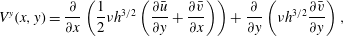 $$\begin{eqnarray}\displaystyle & \displaystyle V^{y}(x,y)={\displaystyle \frac{\unicode[STIX]{x2202}}{\unicode[STIX]{x2202}x}}\left(\frac{1}{2}\unicode[STIX]{x1D708}h^{3/2}\left({\displaystyle \frac{\unicode[STIX]{x2202}\bar{u}}{\unicode[STIX]{x2202}y}}+{\displaystyle \frac{\unicode[STIX]{x2202}\bar{v}}{\unicode[STIX]{x2202}x}}\right)\right)+{\displaystyle \frac{\unicode[STIX]{x2202}}{\unicode[STIX]{x2202}y}}\left(\unicode[STIX]{x1D708}h^{3/2}{\displaystyle \frac{\unicode[STIX]{x2202}\bar{v}}{\unicode[STIX]{x2202}y}}\right), & \displaystyle\end{eqnarray}$$
respectively, where the coefficient
 $\unicode[STIX]{x1D708}$
in the effective viscosity
$\unicode[STIX]{x1D708}$
in the effective viscosity
 $\unicode[STIX]{x1D708}h^{1/2}/2$
is explicitly determined in the depth-integration process and is given by
$\unicode[STIX]{x1D708}h^{1/2}/2$
is explicitly determined in the depth-integration process and is given by
 $$\begin{eqnarray}\unicode[STIX]{x1D708}=\frac{2}{9}\frac{{\mathcal{L}}\sqrt{g}}{\unicode[STIX]{x1D6FD}}\frac{\sin \unicode[STIX]{x1D701}}{\sqrt{\cos \unicode[STIX]{x1D701}}}\left(\frac{\tan \unicode[STIX]{x1D701}_{2}-\tan \unicode[STIX]{x1D701}}{\tan \unicode[STIX]{x1D701}-\tan \unicode[STIX]{x1D701}_{1}}\right),\end{eqnarray}$$
with the parameters
 ${\mathcal{L}}$
,
${\mathcal{L}}$
,
 $\unicode[STIX]{x1D6FD}$
,
$\unicode[STIX]{x1D6FD}$
,
 $\unicode[STIX]{x1D701}_{1}$
and
$\unicode[STIX]{x1D701}_{1}$
and
 $\unicode[STIX]{x1D701}_{2}$
arising from Pouliquen & Forterre’s (Reference Pouliquen and Forterre2002) basal friction law described in § 3. The value of
$\unicode[STIX]{x1D701}_{2}$
arising from Pouliquen & Forterre’s (Reference Pouliquen and Forterre2002) basal friction law described in § 3. The value of
 $\unicode[STIX]{x1D708}$
for the various slope inclinations is summarized in table 2. Strong evidence for these viscous terms is provided by the fact that, unlike the inviscid avalanche model, they predict a downslope velocity profile across a channel with rough side walls (Baker et al.
Reference Baker, Barker and Gray2016a
). The viscous terms are also vital in regularizing depth-averaged models of segregation-induced fingering (Pouliquen, Delour & Savage Reference Pouliquen, Delour and Savage1997; Pouliquen & Vallance Reference Pouliquen and Vallance1999; Woodhouse et al.
Reference Woodhouse, Thornton, Johnson, Kokelaar and Gray2012; Baker, Johnson & Gray Reference Baker, Johnson and Gray2016b
). In addition, the functional dependence on the slope inclination
$\unicode[STIX]{x1D708}$
for the various slope inclinations is summarized in table 2. Strong evidence for these viscous terms is provided by the fact that, unlike the inviscid avalanche model, they predict a downslope velocity profile across a channel with rough side walls (Baker et al.
Reference Baker, Barker and Gray2016a
). The viscous terms are also vital in regularizing depth-averaged models of segregation-induced fingering (Pouliquen, Delour & Savage Reference Pouliquen, Delour and Savage1997; Pouliquen & Vallance Reference Pouliquen and Vallance1999; Woodhouse et al.
Reference Woodhouse, Thornton, Johnson, Kokelaar and Gray2012; Baker, Johnson & Gray Reference Baker, Johnson and Gray2016b
). In addition, the functional dependence on the slope inclination
 $\unicode[STIX]{x1D701}$
and thickness
$\unicode[STIX]{x1D701}$
and thickness
 $h$
to the three-halves power is crucial in matching the cutoff frequency of roll waves without any additional fitting parameters (Gray & Edwards Reference Gray and Edwards2014). It should be noted, however, that the theory is only well posed for slope inclinations in the range of steady uniform flow, i.e. for
$h$
to the three-halves power is crucial in matching the cutoff frequency of roll waves without any additional fitting parameters (Gray & Edwards Reference Gray and Edwards2014). It should be noted, however, that the theory is only well posed for slope inclinations in the range of steady uniform flow, i.e. for
 $\unicode[STIX]{x1D701}\in [\unicode[STIX]{x1D701}_{1},\unicode[STIX]{x1D701}_{2}]$
, reflecting the fact that the full
$\unicode[STIX]{x1D701}\in [\unicode[STIX]{x1D701}_{1},\unicode[STIX]{x1D701}_{2}]$
, reflecting the fact that the full
 $\unicode[STIX]{x1D707}(I)$
-rheology is ill posed for high and low inertial numbers (Barker et al.
Reference Barker, Schaeffer, Bohórquez and Gray2015). Outside of this range of angles some form of regularization is therefore required, i.e. the negative viscosity for
$\unicode[STIX]{x1D707}(I)$
-rheology is ill posed for high and low inertial numbers (Barker et al.
Reference Barker, Schaeffer, Bohórquez and Gray2015). Outside of this range of angles some form of regularization is therefore required, i.e. the negative viscosity for
 $\unicode[STIX]{x1D701}\notin [\unicode[STIX]{x1D701}_{1},\unicode[STIX]{x1D701}_{2}]$
must be prevented.
$\unicode[STIX]{x1D701}\notin [\unicode[STIX]{x1D701}_{1},\unicode[STIX]{x1D701}_{2}]$
must be prevented.
Critical layer thicknesses,
 $h_{stop}$
and
$h_{stop}$
and
 $h_{start}$
, the friction law transition point
$h_{start}$
, the friction law transition point
 $\unicode[STIX]{x1D6FD}_{\ast }$
and the coefficient
$\unicode[STIX]{x1D6FD}_{\ast }$
and the coefficient
 $\unicode[STIX]{x1D708}$
in the depth-averaged viscosity
$\unicode[STIX]{x1D708}$
in the depth-averaged viscosity
 $\unicode[STIX]{x1D708}h^{1/2}/2$
for each experimental slope angle.
$\unicode[STIX]{x1D708}h^{1/2}/2$
for each experimental slope angle.
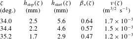
Edwards & Gray (Reference Edwards and Gray2015) found that by using Pouliquen & Forterre’s (Reference Pouliquen and Forterre2002) extended basal friction law, which has additional static and intermediate regimes, it was possible to construct steadily travelling erosion–deposition wave solutions with static and mobile regions. In principle, the form of the viscous term should change when the friction law is in the intermediate or static regimes, i.e. for
 $Fr<\unicode[STIX]{x1D6FD}_{\ast }$
. However, it is not obvious how to achieve this, since there is no longer a steady uniform flow solution to determine the velocity and pressure profiles in the depth-integration process. Neither is it obvious how the offset
$Fr<\unicode[STIX]{x1D6FD}_{\ast }$
. However, it is not obvious how to achieve this, since there is no longer a steady uniform flow solution to determine the velocity and pressure profiles in the depth-integration process. Neither is it obvious how the offset
 $\unicode[STIX]{x1D6E4}$
for angular particles (e.g. sand and carborundum) can be included in the viscosity. However, since the viscous terms represent a singular perturbation to the equations (i.e. they are the highest-order derivatives, but most of the time they are very small), the simple form in (4.6)–(4.7) with the viscous coefficient (4.8) are assumed to apply to all regimes in this paper.
$\unicode[STIX]{x1D6E4}$
for angular particles (e.g. sand and carborundum) can be included in the viscosity. However, since the viscous terms represent a singular perturbation to the equations (i.e. they are the highest-order derivatives, but most of the time they are very small), the simple form in (4.6)–(4.7) with the viscous coefficient (4.8) are assumed to apply to all regimes in this paper.
4.2 Numerical method
The standard depth-averaged avalanche equations (e.g. Gray et al.
Reference Gray, Tai and Noelle2003) represent a system of hyperbolic equations that require high-resolution shock capturing numerical methods (e.g. Nessyahu & Tadmor Reference Nessyahu and Tadmor1990) to solve them. Although our problems are still convection dominated the inclusion of the depth-averaged
 $\unicode[STIX]{x1D707}(I)$
-rheology (Gray & Edwards Reference Gray and Edwards2014; Baker et al.
Reference Baker, Barker and Gray2016a
) changes the system into a set of convection–diffusion equations. This paper therefore uses the closely related semi-discrete high-resolution non-oscillatory central schemes of Kurganov & Tadmor (Reference Kurganov and Tadmor2000) together with a second-order Runge–Kutta method, with a step size of
$\unicode[STIX]{x1D707}(I)$
-rheology (Gray & Edwards Reference Gray and Edwards2014; Baker et al.
Reference Baker, Barker and Gray2016a
) changes the system into a set of convection–diffusion equations. This paper therefore uses the closely related semi-discrete high-resolution non-oscillatory central schemes of Kurganov & Tadmor (Reference Kurganov and Tadmor2000) together with a second-order Runge–Kutta method, with a step size of
 $10^{-4}$
s, for their time evolution. The scheme has been tested against the one-dimensional travelling wave solutions of Edwards & Gray (Reference Edwards and Gray2015) and the value of the time step has been chosen to minimize the small variations in the static layer thickness due to overshoots, while maximizing the efficiency of the computation. The travelling wave results have also been validated by using an alternative third-order Runge–Kutta adaptive step method (Medovikov Reference Medovikov1998) for the time evolution, although this method is much more computationally expensive.
$10^{-4}$
s, for their time evolution. The scheme has been tested against the one-dimensional travelling wave solutions of Edwards & Gray (Reference Edwards and Gray2015) and the value of the time step has been chosen to minimize the small variations in the static layer thickness due to overshoots, while maximizing the efficiency of the computation. The travelling wave results have also been validated by using an alternative third-order Runge–Kutta adaptive step method (Medovikov Reference Medovikov1998) for the time evolution, although this method is much more computationally expensive.
In order to solve the system, the depth-averaged equations (4.1)–(4.7) together with the friction law (3.15) are written in conservative vector form as
 $$\begin{eqnarray}{\displaystyle \frac{\unicode[STIX]{x2202}\boldsymbol{w}}{\unicode[STIX]{x2202}t}}+{\displaystyle \frac{\unicode[STIX]{x2202}\boldsymbol{f}(\boldsymbol{w})}{\unicode[STIX]{x2202}x}}+{\displaystyle \frac{\unicode[STIX]{x2202}\boldsymbol{g}(\boldsymbol{w})}{\unicode[STIX]{x2202}y}}=\boldsymbol{S}(\boldsymbol{w})+{\displaystyle \frac{\unicode[STIX]{x2202}}{\unicode[STIX]{x2202}x}}(\boldsymbol{Q}(\boldsymbol{w},\boldsymbol{w}_{x},\boldsymbol{w}_{y}))+{\displaystyle \frac{\unicode[STIX]{x2202}}{\unicode[STIX]{x2202}y}}(\boldsymbol{R}(\boldsymbol{w},\boldsymbol{w}_{x},\boldsymbol{w}_{y})),\end{eqnarray}$$
where
 $\boldsymbol{w}=(h,m,n)^{\text{T}}$
is the vector of conservative variables
$\boldsymbol{w}=(h,m,n)^{\text{T}}$
is the vector of conservative variables
 $h$
,
$h$
,
 $m=h\bar{u}$
and
$m=h\bar{u}$
and
 $n=h\bar{v}$
, and the subscripts denote partial derivatives. The resulting convection flux functions
$n=h\bar{v}$
, and the subscripts denote partial derivatives. The resulting convection flux functions
 $\boldsymbol{f}$
and
$\boldsymbol{f}$
and
 $\boldsymbol{g}$
, and the source term vector
$\boldsymbol{g}$
, and the source term vector
 $\boldsymbol{S}=(0,S^{x},S^{y})^{\text{T}}$
are
$\boldsymbol{S}=(0,S^{x},S^{y})^{\text{T}}$
are
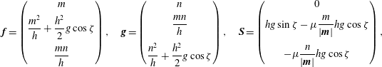 $$\begin{eqnarray}\boldsymbol{f}=\left(\begin{array}{@{}c@{}}m\\ {\displaystyle \frac{m^{2}}{h}}+{\displaystyle \frac{h^{2}}{2}}g\cos \unicode[STIX]{x1D701}\\ {\displaystyle \frac{mn}{h}}\end{array}\right),\quad \boldsymbol{g}=\left(\begin{array}{@{}c@{}}n\\ {\displaystyle \frac{mn}{h}}\\ {\displaystyle \frac{n^{2}}{h}}+{\displaystyle \frac{h^{2}}{2}}g\cos \unicode[STIX]{x1D701}\end{array}\right),\quad \boldsymbol{S}=\left(\begin{array}{@{}c@{}}0\\ hg\sin \unicode[STIX]{x1D701}-\unicode[STIX]{x1D707}{\displaystyle \frac{m}{|\boldsymbol{m}|}}hg\cos \unicode[STIX]{x1D701}\\ -\unicode[STIX]{x1D707}{\displaystyle \frac{n}{|\boldsymbol{m}|}}hg\cos \unicode[STIX]{x1D701}\end{array}\right),\end{eqnarray}$$
respectively, where the vector of mass fluxes
 $\boldsymbol{m}=(m,n)^{\text{T}}$
. The diffusive flux functions are given by
$\boldsymbol{m}=(m,n)^{\text{T}}$
. The diffusive flux functions are given by
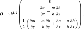 $$\begin{eqnarray}\boldsymbol{Q}=\unicode[STIX]{x1D708}h^{1/2}\left(\begin{array}{@{}c@{}}0\\ {\displaystyle \frac{\unicode[STIX]{x2202}m}{\unicode[STIX]{x2202}x}}-{\displaystyle \frac{m}{h}}{\displaystyle \frac{\unicode[STIX]{x2202}h}{\unicode[STIX]{x2202}x}}\\ {\displaystyle \frac{1}{2}}\left({\displaystyle \frac{\unicode[STIX]{x2202}m}{\unicode[STIX]{x2202}y}}-{\displaystyle \frac{m}{h}}{\displaystyle \frac{\unicode[STIX]{x2202}h}{\unicode[STIX]{x2202}y}}+{\displaystyle \frac{\unicode[STIX]{x2202}n}{\unicode[STIX]{x2202}x}}-{\displaystyle \frac{n}{h}}{\displaystyle \frac{\unicode[STIX]{x2202}h}{\unicode[STIX]{x2202}x}}\right)\end{array}\right),\end{eqnarray}$$
and
 $$\begin{eqnarray}\boldsymbol{R}=\unicode[STIX]{x1D708}h^{1/2}\left(\begin{array}{@{}c@{}}0\\ {\displaystyle \frac{1}{2}}\left({\displaystyle \frac{\unicode[STIX]{x2202}n}{\unicode[STIX]{x2202}x}}-{\displaystyle \frac{n}{h}}{\displaystyle \frac{\unicode[STIX]{x2202}h}{\unicode[STIX]{x2202}x}}+{\displaystyle \frac{\unicode[STIX]{x2202}m}{\unicode[STIX]{x2202}y}}-{\displaystyle \frac{m}{h}}{\displaystyle \frac{\unicode[STIX]{x2202}h}{\unicode[STIX]{x2202}y}}\right)\\ {\displaystyle \frac{\unicode[STIX]{x2202}n}{\unicode[STIX]{x2202}y}}-{\displaystyle \frac{n}{h}}{\displaystyle \frac{\unicode[STIX]{x2202}h}{\unicode[STIX]{x2202}y}}\end{array}\right).\end{eqnarray}$$
For the problems of interest here the flows are subcritical
 $(Fr<1)$
everywhere, which requires two inflow conditions and one outflow condition to be specified for the hyperbolic system (e.g. Weiyan Reference Weiyan1992). The introduction of diffusive terms means that the system is now parabolic and an extra boundary condition is required, which is applied here at the outflow end of the domain. Periodic boundary conditions are imposed at the cross-slope boundaries, although there is no flow across them in any of the following simulations.
$(Fr<1)$
everywhere, which requires two inflow conditions and one outflow condition to be specified for the hyperbolic system (e.g. Weiyan Reference Weiyan1992). The introduction of diffusive terms means that the system is now parabolic and an extra boundary condition is required, which is applied here at the outflow end of the domain. Periodic boundary conditions are imposed at the cross-slope boundaries, although there is no flow across them in any of the following simulations.
5 Numerical simulations on a two-dimensional plane
The two-dimensional system of conservative equations (4.9)–(4.12), with the friction law (3.15), are solved numerically for the experimental configurations described in § 2. A rectangular computational domain is defined in the range
 $-5\leqslant x\leqslant 95$
cm,
$-5\leqslant x\leqslant 95$
cm,
 $-10~\text{cm}\leqslant y\leqslant 10$
cm and is discretized with 1000 grid points in the
$-10~\text{cm}\leqslant y\leqslant 10$
cm and is discretized with 1000 grid points in the
 $x$
-direction and 100 grid points in the
$x$
-direction and 100 grid points in the
 $y$
-direction. The initial conditions are of a cylindrical mass of radius
$y$
-direction. The initial conditions are of a cylindrical mass of radius
 $R=1.4$
cm and height
$R=1.4$
cm and height
 $h_{c}=1.6$
cm centred at
$h_{c}=1.6$
cm centred at
 $(x,y)=(0,0)$
on top of a layer of thickness
$(x,y)=(0,0)$
on top of a layer of thickness
 $h=h_{0}$
, with
$h=h_{0}$
, with
 $m=n=0$
everywhere. This will be referred to as the standard release. As the column of grains collapses it sets the previously static particles immediately downstream of the cylinder into motion to form an avalanche. At the downstream boundary
$m=n=0$
everywhere. This will be referred to as the standard release. As the column of grains collapses it sets the previously static particles immediately downstream of the cylinder into motion to form an avalanche. At the downstream boundary
 $x=0.95$
m free outflow is imposed via a linear extrapolation of the values of
$x=0.95$
m free outflow is imposed via a linear extrapolation of the values of
 $h$
and
$h$
and
 $m$
from the final two columns of interior cells. At the upstream boundary
$m$
from the final two columns of interior cells. At the upstream boundary
 $x=-0.05$
m, a stationary inflow is imposed with
$x=-0.05$
m, a stationary inflow is imposed with
 $h=h_{0}$
and
$h=h_{0}$
and
 $m=0$
.
$m=0$
.
Numerical simulations of the standard release on a static layer of thickness
 $h_{0}=2.2$
mm on a slope angle of
$h_{0}=2.2$
mm on a slope angle of
 $\unicode[STIX]{x1D701}=35.2^{\circ }$
at times (a)
$\unicode[STIX]{x1D701}=35.2^{\circ }$
at times (a)
 $t=0.5$
, (b)
$t=0.5$
, (b)
 $t=1.0$
, (c)
$t=1.0$
, (c)
 $t=1.5$
, (d)
$t=1.5$
, (d)
 $t=2.0$
and (e)
$t=2.0$
and (e)
 $t=2.5$
s. Contours of thickness
$t=2.5$
s. Contours of thickness
 $h$
are plotted in the
$h$
are plotted in the
 $(x,y)$
-plane in increasing increments of 0.2 mm inwards from the outer contour at 2.3 mm (solid lines), whilst the trough contour is at
$(x,y)$
-plane in increasing increments of 0.2 mm inwards from the outer contour at 2.3 mm (solid lines), whilst the trough contour is at
 $h=2.1$
mm (dashed line, 0.1 mm below
$h=2.1$
mm (dashed line, 0.1 mm below
 $h_{0}$
). The shaded grey area indicates where the depth-averaged downslope velocity component
$h_{0}$
). The shaded grey area indicates where the depth-averaged downslope velocity component
 $\bar{u}$
is non-zero. A movie showing the time-dependent evolution is available in the online supplementary material (movie 4).
$\bar{u}$
is non-zero. A movie showing the time-dependent evolution is available in the online supplementary material (movie 4).

5.1 Growing avalanches
Simulations are performed to model the growing avalanche shown in figure 4. The slope angle is set to
 $\unicode[STIX]{x1D701}=35.2^{\circ }$
and a deep deposit layer of thickness
$\unicode[STIX]{x1D701}=35.2^{\circ }$
and a deep deposit layer of thickness
 $h_{0}=2.2$
mm is prescribed, which is equivalent to
$h_{0}=2.2$
mm is prescribed, which is equivalent to
 $h_{stop}(34.4^{\circ })=2.2$
mm on a shallower slope. The results are plotted as thickness contours in the
$h_{stop}(34.4^{\circ })=2.2$
mm on a shallower slope. The results are plotted as thickness contours in the
 $(x,y)$
-plane at various times in figure 12. The region that is in motion is shaded grey and the dashed contour at 2.1 mm approximately delineates the outer boundary of the static trough deposit that forms behind the avalanche, which is thinner than the undisturbed erodible layer. A movie is available in the online supplementary material (movie 4). As the avalanche propagates downslope it erodes the thick layer in front of it and progressively grows in size by depositing less material behind it and by broadening laterally. By
$(x,y)$
-plane at various times in figure 12. The region that is in motion is shaded grey and the dashed contour at 2.1 mm approximately delineates the outer boundary of the static trough deposit that forms behind the avalanche, which is thinner than the undisturbed erodible layer. A movie is available in the online supplementary material (movie 4). As the avalanche propagates downslope it erodes the thick layer in front of it and progressively grows in size by depositing less material behind it and by broadening laterally. By
 $x_{L}=30$
cm it is approximately 14 cm wide, which is roughly 25 % wider than the experimental avalanche, but it has qualitatively the correct behaviour. As a result, the maximal extent of the trough has a triangular shape, which is consistent with the experimental results of Daerr & Douady (Reference Daerr and Douady1999). As the avalanche bulks up, the wave accelerates slightly, although over the length of the chute its wavespeed remains close to its mean value of
$x_{L}=30$
cm it is approximately 14 cm wide, which is roughly 25 % wider than the experimental avalanche, but it has qualitatively the correct behaviour. As a result, the maximal extent of the trough has a triangular shape, which is consistent with the experimental results of Daerr & Douady (Reference Daerr and Douady1999). As the avalanche bulks up, the wave accelerates slightly, although over the length of the chute its wavespeed remains close to its mean value of
 $u_{w}=0.31~\text{m}~\text{s}^{-1}$
, which is slightly greater than the experimental value of
$u_{w}=0.31~\text{m}~\text{s}^{-1}$
, which is slightly greater than the experimental value of
 $0.26~\text{m}~\text{s}^{-1}$
.
$0.26~\text{m}~\text{s}^{-1}$
.
In order to compare the numerical simulations with the experimental results shown in figure 5, the flow thickness contours in the
 $(t,y)$
-plane and the temporal evolution of the flow thickness on the centreline are plotted in figure 13. The temporal evolution of the downslope velocity on the centreline and the final static layer depth across the plane at
$(t,y)$
-plane and the temporal evolution of the flow thickness on the centreline are plotted in figure 13. The temporal evolution of the downslope velocity on the centreline and the final static layer depth across the plane at
 $x_{L}=30$
cm are also shown. The plots in figure 13(b,c) show that the avalanche develops into a classical erosion–deposition wave soon after the initial collapse, with the highest velocities occurring during the peak of the wave, which has a sharp front and a more gradual decay of both height and velocity in the tail. Outside of the wave the velocity is zero. The avalanche peak height at
$x_{L}=30$
cm are also shown. The plots in figure 13(b,c) show that the avalanche develops into a classical erosion–deposition wave soon after the initial collapse, with the highest velocities occurring during the peak of the wave, which has a sharp front and a more gradual decay of both height and velocity in the tail. Outside of the wave the velocity is zero. The avalanche peak height at
 $x_{L}=50$
cm is
$x_{L}=50$
cm is
 $h_{w}=5.8$
mm, which is only slightly less than the experimental value of approximately 5.9 mm. As the wave propagates downslope it erodes more grains from the front than it deposits in the tail, and the incised trough becomes progressively deeper further downstream, reaching
$h_{w}=5.8$
mm, which is only slightly less than the experimental value of approximately 5.9 mm. As the wave propagates downslope it erodes more grains from the front than it deposits in the tail, and the incised trough becomes progressively deeper further downstream, reaching
 $h_{deposit}=1.6$
mm at
$h_{deposit}=1.6$
mm at
 $x_{L}=50$
cm. This is slightly lower than the experimental value of
$x_{L}=50$
cm. This is slightly lower than the experimental value of
 $1.7\pm 0.2$
mm. The cross-section in figure 13(d) shows that after the avalanche has passed by there is a strongly incised trough, which has a base that is 0.6 mm lower than the initial deposit thickness. At the sides are some very small levees, but they are not big enough to balance the mass that has been lost, so that this channel is typical of a growing avalanche. Overall the model produces a slightly wider flowing region, with a shorter thinner avalanche than is observed experimentally. However, the important features of the experimental flow are captured in the simulations and the results are qualitatively comparable, as they produce an avalanche that is continually growing in width and in wave peak height.
$1.7\pm 0.2$
mm. The cross-section in figure 13(d) shows that after the avalanche has passed by there is a strongly incised trough, which has a base that is 0.6 mm lower than the initial deposit thickness. At the sides are some very small levees, but they are not big enough to balance the mass that has been lost, so that this channel is typical of a growing avalanche. Overall the model produces a slightly wider flowing region, with a shorter thinner avalanche than is observed experimentally. However, the important features of the experimental flow are captured in the simulations and the results are qualitatively comparable, as they produce an avalanche that is continually growing in width and in wave peak height.
Numerical simulations of the standard release on a static layer of thickness
 $h_{0}=2.2$
mm inclined at
$h_{0}=2.2$
mm inclined at
 $\unicode[STIX]{x1D701}=35.2^{\circ }$
. The results are plotted at three downslope positions
$\unicode[STIX]{x1D701}=35.2^{\circ }$
. The results are plotted at three downslope positions
 $x_{L}=12$
,
$x_{L}=12$
,
 $x_{L}=30$
and
$x_{L}=30$
and
 $x_{L}=50$
cm (from left to right) as (a) contours of constant flow thickness in the
$x_{L}=50$
cm (from left to right) as (a) contours of constant flow thickness in the
 $(t,y)$
-plane in increasing increments of 0.2 mm inwards from the outer contour at 2.3 mm (solid lines), whilst the trough contour is at
$(t,y)$
-plane in increasing increments of 0.2 mm inwards from the outer contour at 2.3 mm (solid lines), whilst the trough contour is at
 $h=2.1$
mm (dashed line, 0.1 mm below
$h=2.1$
mm (dashed line, 0.1 mm below
 $h_{0}$
), (b) flow thickness
$h_{0}$
), (b) flow thickness
 $h$
along the midpoint of the plane,
$h$
along the midpoint of the plane,
 $y=0$
, and (c) the depth-averaged downslope velocity component
$y=0$
, and (c) the depth-averaged downslope velocity component
 $\bar{u}$
along the midpoint of the plane, versus time
$\bar{u}$
along the midpoint of the plane, versus time
 $t$
. The avalanche deposit in the cross-slope
$t$
. The avalanche deposit in the cross-slope
 $y$
-direction at
$y$
-direction at
 $x_{L}=30$
cm is shown in (d) for all times after the material at that position has come to rest.
$x_{L}=30$
cm is shown in (d) for all times after the material at that position has come to rest.
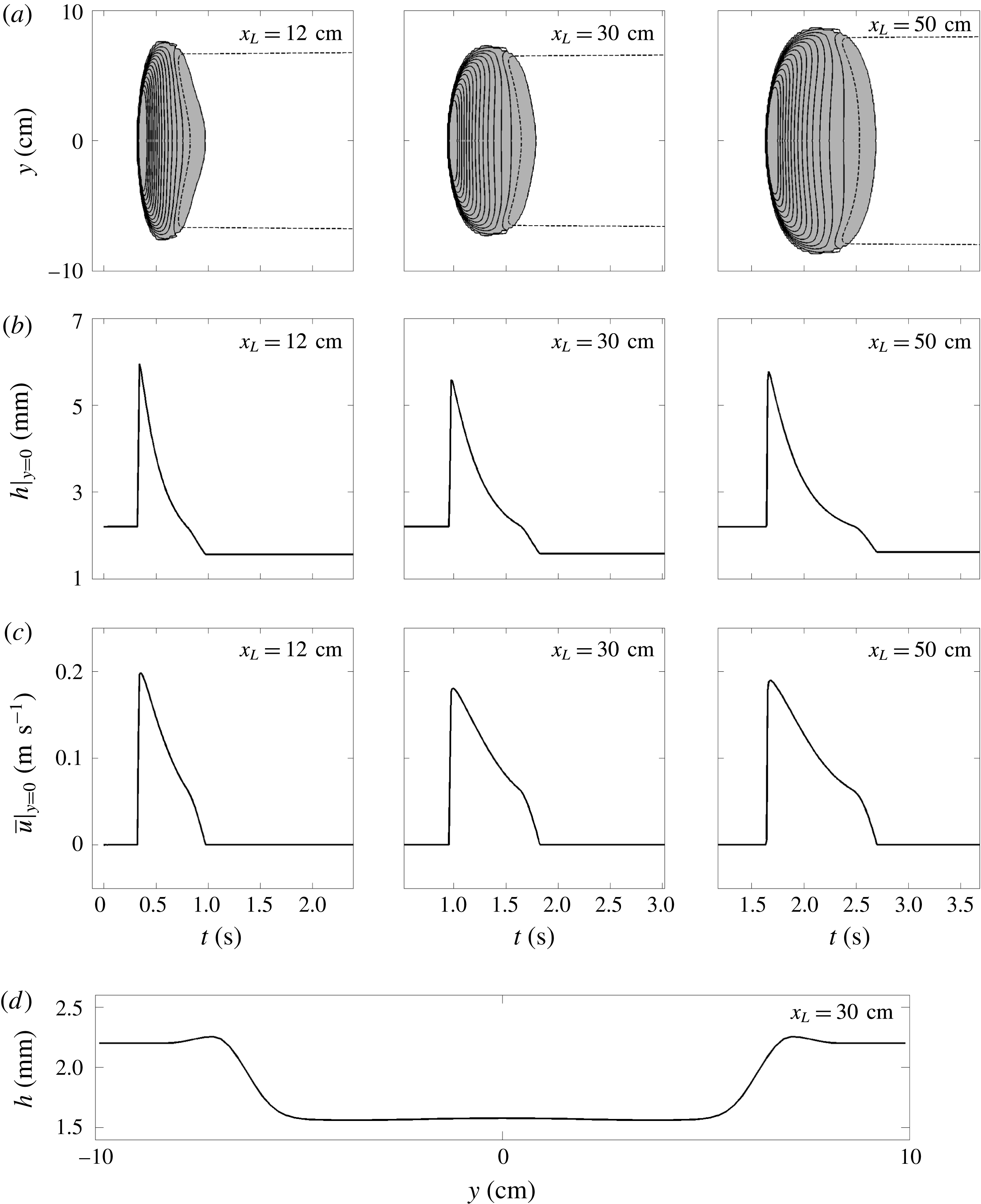
There are several possible reasons for the apparently increased width of the numerical simulations as compared to the experiments. One possibility is that the friction law (3.15) is still not perfect, and that by modifying it one might be able to get closer to the experiments. Another possibility is that the relatively crude representation of the deposition mechanism is at fault, and that to get better agreement the interface between flowing and non-flowing material really does have to be resolved in the vertical. Unfortunately there is no accepted way of doing this yet. A final possibility is that the initial collapse from the cylinder may not be captured well in the depth-averaged framework. Certainly a few of the grains are stranded at the experimental release point and do not, as assumed, propagate down the plane. This would reduce the mass that should be used in the simulations and hence also produce a width reduction. Better agreement between theory and experiment could also potentially be achieved by commencing the simulations once the avalanche is shallow. However, this has not been done here, because it would require us to prescribe the unknown thickness and velocity fields at this later time.
Numerical simulations of the standard release on a static layer of thickness
 $h_{0}=2.5$
mm and on a slope angle of
$h_{0}=2.5$
mm and on a slope angle of
 $\unicode[STIX]{x1D701}=34.1^{\circ }$
at times (a)
$\unicode[STIX]{x1D701}=34.1^{\circ }$
at times (a)
 $t=0.5$
, (b)
$t=0.5$
, (b)
 $t=1.0$
, (c)
$t=1.0$
, (c)
 $t=1.5$
, (d)
$t=1.5$
, (d)
 $t=2.0$
and (e)
$t=2.0$
and (e)
 $t=2.5$
s. Contours of thickness
$t=2.5$
s. Contours of thickness
 $h$
are plotted in the
$h$
are plotted in the
 $(x,y)$
-plane in increasing increments of 0.2 mm inwards from the outer contour at 2.8 mm (solid lines), whilst the deposit contour is at
$(x,y)$
-plane in increasing increments of 0.2 mm inwards from the outer contour at 2.8 mm (solid lines), whilst the deposit contour is at
 $h=2.6$
mm (dashed line, 0.1 mm above
$h=2.6$
mm (dashed line, 0.1 mm above
 $h_{0}$
). The shaded grey area indicates where the depth-averaged downslope velocity component
$h_{0}$
). The shaded grey area indicates where the depth-averaged downslope velocity component
 $\bar{u}$
is non-zero. A movie showing the time-dependent evolution is available in the online supplementary material (movie 5). Note that the domain size corresponds with the experimental images in figure 6.
$\bar{u}$
is non-zero. A movie showing the time-dependent evolution is available in the online supplementary material (movie 5). Note that the domain size corresponds with the experimental images in figure 6.

Numerical simulations of the standard release on a static layer of thickness
 $h_{0}=2.5$
mm and at a slope angle of
$h_{0}=2.5$
mm and at a slope angle of
 $\unicode[STIX]{x1D701}=34.1^{\circ }$
. The results are plotted at three downslope positions
$\unicode[STIX]{x1D701}=34.1^{\circ }$
. The results are plotted at three downslope positions
 $x_{L}=12$
,
$x_{L}=12$
,
 $x_{L}=30$
and
$x_{L}=30$
and
 $x_{L}=50$
cm downslope (from left to right) as (a) contours of constant flow thickness
$x_{L}=50$
cm downslope (from left to right) as (a) contours of constant flow thickness
 $h$
in the
$h$
in the
 $(t,y)$
-plane in increasing increments of 0.2 mm inwards from the outer contour at 2.8 mm (solid lines), whilst the deposit contour is at
$(t,y)$
-plane in increasing increments of 0.2 mm inwards from the outer contour at 2.8 mm (solid lines), whilst the deposit contour is at
 $h=2.6$
mm (dashed line, 0.1 mm above
$h=2.6$
mm (dashed line, 0.1 mm above
 $h_{0}$
), (b) flow thickness
$h_{0}$
), (b) flow thickness
 $h$
along the midpoint of the plane,
$h$
along the midpoint of the plane,
 $y=0$
, and (c) the depth-averaged downslope velocity component
$y=0$
, and (c) the depth-averaged downslope velocity component
 $\bar{u}$
along the midpoint of the plane, versus time
$\bar{u}$
along the midpoint of the plane, versus time
 $t$
. The avalanche deposit in the cross-slope
$t$
. The avalanche deposit in the cross-slope
 $y$
-direction at
$y$
-direction at
 $x_{L}=30$
cm is shown in (d) for all times after the material at that position has come to rest.
$x_{L}=30$
cm is shown in (d) for all times after the material at that position has come to rest.
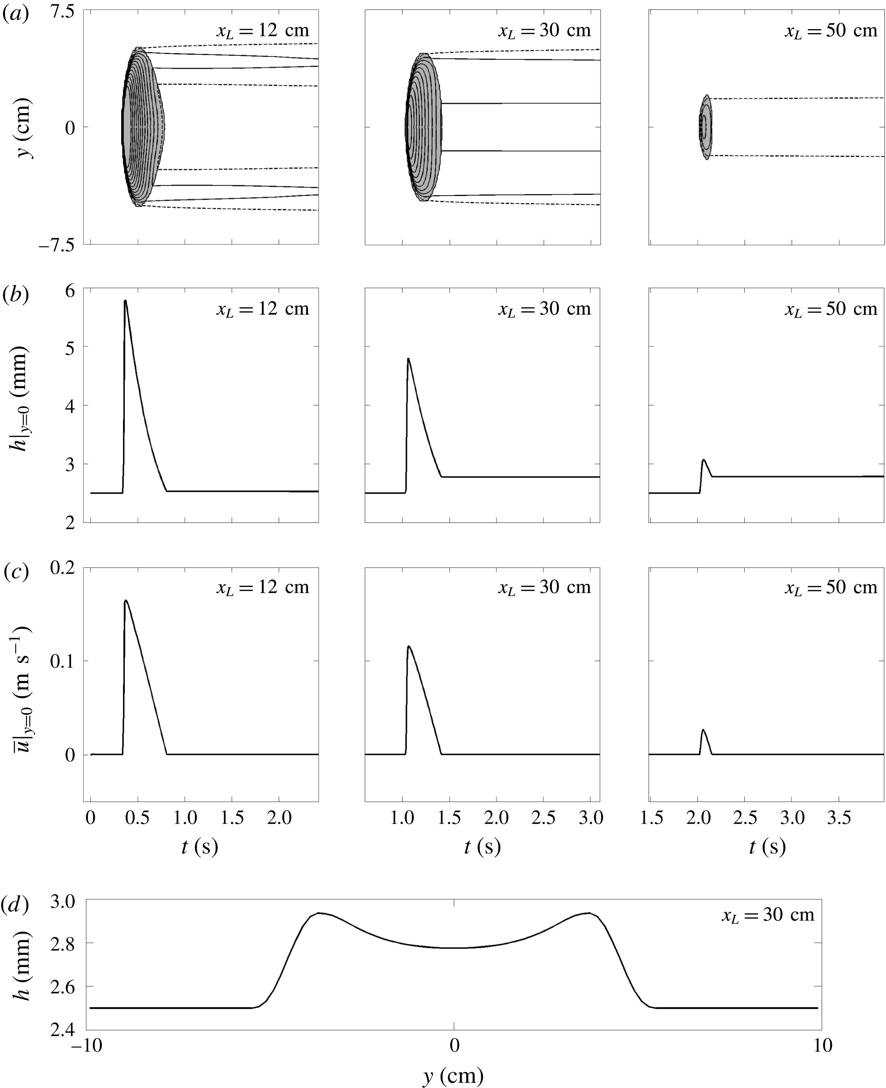
5.2 Decaying avalanches
With the slope at
 $\unicode[STIX]{x1D701}=34.1^{\circ }$
and the static layer thickness at
$\unicode[STIX]{x1D701}=34.1^{\circ }$
and the static layer thickness at
 $h_{0}=2.5$
mm, equal to the theoretical
$h_{0}=2.5$
mm, equal to the theoretical
 $h_{stop}$
for
$h_{stop}$
for
 $34.1^{\circ }$
, the standard release again generates a three-dimensional erosion–deposition wave that propagates downslope. This time, however, the contour plots in figure 14 show that there is net deposition and by
$34.1^{\circ }$
, the standard release again generates a three-dimensional erosion–deposition wave that propagates downslope. This time, however, the contour plots in figure 14 show that there is net deposition and by
 $t=2.5$
s the avalanche has completely stopped. The shape of the deposit and the final stopping position of the head, at
$t=2.5$
s the avalanche has completely stopped. The shape of the deposit and the final stopping position of the head, at
 $x=53$
cm, are very close to the experiments shown in figure 6, where the maximum distance reached by the avalanche is 55 cm. The space–time plots in figure 15(a,b) indicate that the avalanche is again wider than in the experiments in figure 7, but that the model otherwise accurately captures the deposition of mass. At
$x=53$
cm, are very close to the experiments shown in figure 6, where the maximum distance reached by the avalanche is 55 cm. The space–time plots in figure 15(a,b) indicate that the avalanche is again wider than in the experiments in figure 7, but that the model otherwise accurately captures the deposition of mass. At
 $x_{L}=30$
cm the deposit thickness in the centre of the channel
$x_{L}=30$
cm the deposit thickness in the centre of the channel
 $h_{deposit}=2.8$
mm, which is very close to the experimental value of 2.7 mm. The cross-section in figure 15(d) shows that the avalanche is leaving behind an elevated channel, which is everywhere higher than the undisturbed deposit and which is flanked by small levees. This cross-slope profile is typical of a depositing flow, and as one progresses downstream the elevated channel narrows. During the flowing phase the avalanche has an almost constant wavespeed
$h_{deposit}=2.8$
mm, which is very close to the experimental value of 2.7 mm. The cross-section in figure 15(d) shows that the avalanche is leaving behind an elevated channel, which is everywhere higher than the undisturbed deposit and which is flanked by small levees. This cross-slope profile is typical of a depositing flow, and as one progresses downstream the elevated channel narrows. During the flowing phase the avalanche has an almost constant wavespeed
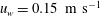 $u_{w}=0.15~\text{m}~\text{s}^{-1}$
, which is moderately larger than the experimental value of approximately
$u_{w}=0.15~\text{m}~\text{s}^{-1}$
, which is moderately larger than the experimental value of approximately
 $0.13~\text{m}~\text{s}^{-1}$
. However, figure 15(b,c) shows that as the avalanche propagates downslope both the peak thickness and the magnitude of the velocities decrease. At
$0.13~\text{m}~\text{s}^{-1}$
. However, figure 15(b,c) shows that as the avalanche propagates downslope both the peak thickness and the magnitude of the velocities decrease. At
 $x_{L}=30$
cm the peak height
$x_{L}=30$
cm the peak height
 $h_{w}=4.8$
mm, which is slightly less than the experiments where the thickness is approximately 5.0 mm. This suggests that the model is again allowing for a wider spread of material into a shorter and thinner avalanche than is observed experimentally, but that all the main attributes are qualitatively captured and the quantitative comparison is still good.
$h_{w}=4.8$
mm, which is slightly less than the experiments where the thickness is approximately 5.0 mm. This suggests that the model is again allowing for a wider spread of material into a shorter and thinner avalanche than is observed experimentally, but that all the main attributes are qualitatively captured and the quantitative comparison is still good.
5.3 Steady avalanches
Numerical simulations of the standard release on a static layer of thickness
 $h_{0}=1.7$
mm on a slope angle of
$h_{0}=1.7$
mm on a slope angle of
 $\unicode[STIX]{x1D701}=35.2^{\circ }$
at times (a)
$\unicode[STIX]{x1D701}=35.2^{\circ }$
at times (a)
 $t=0.5$
, (b)
$t=0.5$
, (b)
 $t=1.3$
, (c)
$t=1.3$
, (c)
 $t=2.1$
, (d)
$t=2.1$
, (d)
 $t=2.9$
and (e)
$t=2.9$
and (e)
 $t=3.7$
s. Contours of thickness
$t=3.7$
s. Contours of thickness
 $h$
are plotted in the
$h$
are plotted in the
 $(x,y)$
-plane in increasing increments of 0.2 mm inwards from the outer contour at 2.0 mm (solid lines), whilst the deposit contour is at
$(x,y)$
-plane in increasing increments of 0.2 mm inwards from the outer contour at 2.0 mm (solid lines), whilst the deposit contour is at
 $h=1.8$
mm (dashed line, 0.1 mm above
$h=1.8$
mm (dashed line, 0.1 mm above
 $h_{0}$
). The shaded grey area indicates where the depth-averaged downslope velocity component
$h_{0}$
). The shaded grey area indicates where the depth-averaged downslope velocity component
 $\bar{u}$
is non-zero. A movie showing the time-dependent evolution is available in the online supplementary material (movie 6).
$\bar{u}$
is non-zero. A movie showing the time-dependent evolution is available in the online supplementary material (movie 6).
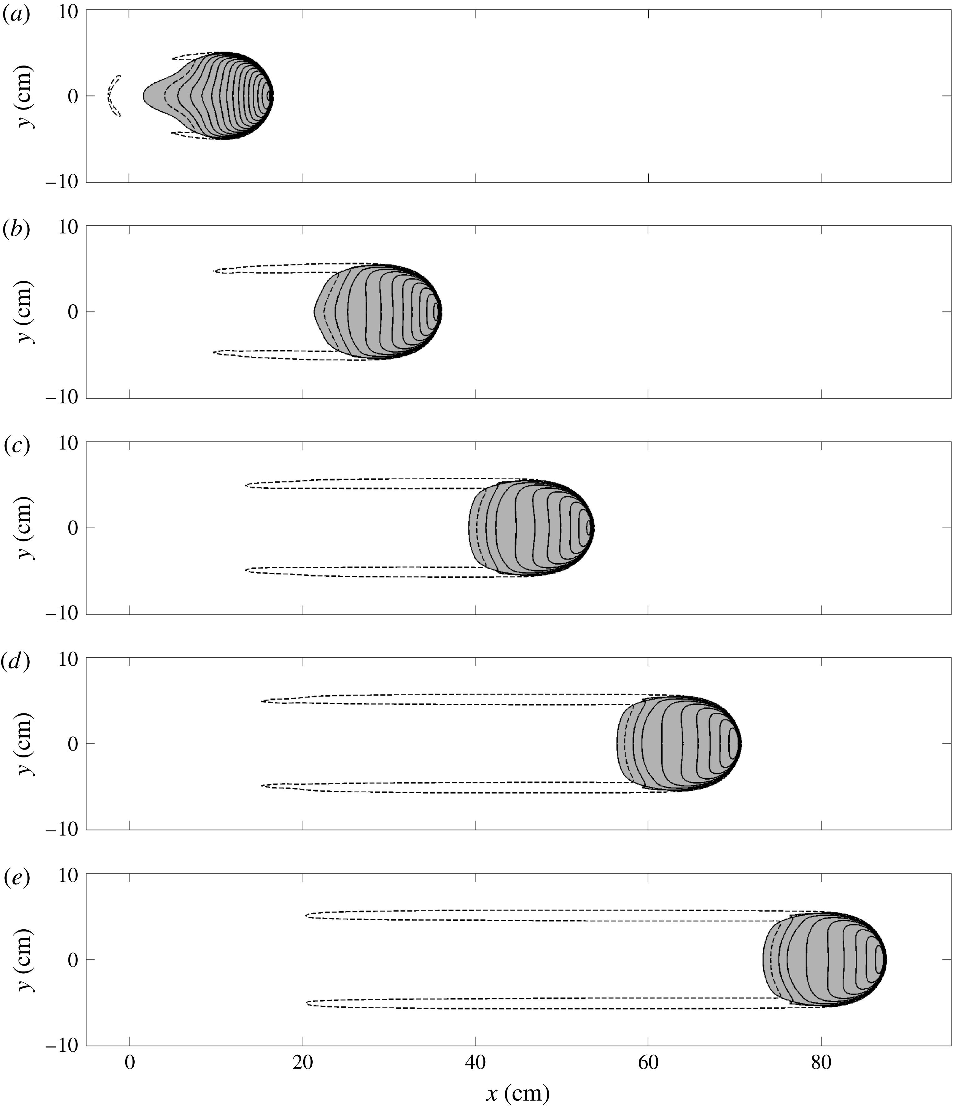
Numerical simulations of the standard release on a static layer of thickness
 $h_{0}=1.7$
mm and at a slope angle of
$h_{0}=1.7$
mm and at a slope angle of
 $\unicode[STIX]{x1D701}=35.2^{\circ }$
. The results are plotted at three downslope positions
$\unicode[STIX]{x1D701}=35.2^{\circ }$
. The results are plotted at three downslope positions
 $x_{L}=12$
,
$x_{L}=12$
,
 $x_{L}=30$
and
$x_{L}=30$
and
 $x_{L}=50$
cm (from left to right) as (a) contours of constant flow thickness
$x_{L}=50$
cm (from left to right) as (a) contours of constant flow thickness
 $h$
in the
$h$
in the
 $(t,y)$
-plane in increasing increments of 0.2 mm inwards from the outer contour at 2.0 mm (solid lines), whilst the deposit contour is at
$(t,y)$
-plane in increasing increments of 0.2 mm inwards from the outer contour at 2.0 mm (solid lines), whilst the deposit contour is at
 $h=1.8$
mm (dashed line, 0.1 mm above
$h=1.8$
mm (dashed line, 0.1 mm above
 $h_{0}$
), (b) flow thickness
$h_{0}$
), (b) flow thickness
 $h$
along the midpoint of the plane,
$h$
along the midpoint of the plane,
 $y=0$
, and (c) the depth-averaged downslope velocity component
$y=0$
, and (c) the depth-averaged downslope velocity component
 $\bar{u}$
along the midpoint of the plane, versus time
$\bar{u}$
along the midpoint of the plane, versus time
 $t$
. The avalanche deposit in the cross-slope
$t$
. The avalanche deposit in the cross-slope
 $y$
-direction at
$y$
-direction at
 $x_{L}=30$
cm is shown in (d) for all times after the material at that position has come to rest.
$x_{L}=30$
cm is shown in (d) for all times after the material at that position has come to rest.
Perhaps most interestingly, with the slope at
 $\unicode[STIX]{x1D701}=35.2^{\circ }$
and the static layer thickness
$\unicode[STIX]{x1D701}=35.2^{\circ }$
and the static layer thickness
 $h_{0}=1.7$
mm (equal to
$h_{0}=1.7$
mm (equal to
 $h_{stop}(35.2^{\circ })$
and the experimental value of
$h_{stop}(35.2^{\circ })$
and the experimental value of
 $h_{0}\approx 1.7$
mm) after the initial collapse the avalanche appears to approach a steadily travelling wave as shown in figure 16. In order for this to occur there has to be a perfect balance between the erosion of material at the front of the avalanche and the deposition that occurs behind it. The wavespeed is calculated by measuring the distance travelled by the wave peak in the time after the initial spreading and before it leaves the computational domain, and is found here to be
$h_{0}\approx 1.7$
mm) after the initial collapse the avalanche appears to approach a steadily travelling wave as shown in figure 16. In order for this to occur there has to be a perfect balance between the erosion of material at the front of the avalanche and the deposition that occurs behind it. The wavespeed is calculated by measuring the distance travelled by the wave peak in the time after the initial spreading and before it leaves the computational domain, and is found here to be
 $u_{w}=0.21~\text{m}~\text{s}^{-1}$
, which is only slightly greater than the value of
$u_{w}=0.21~\text{m}~\text{s}^{-1}$
, which is only slightly greater than the value of
 $0.20~\text{m}~\text{s}^{-1}$
found in experiments. The space–time plots in figure 17(a–c) indicate that after the initial collapse the avalanche quickly attains a constant width
$0.20~\text{m}~\text{s}^{-1}$
found in experiments. The space–time plots in figure 17(a–c) indicate that after the initial collapse the avalanche quickly attains a constant width
 $W\approx 11$
cm, which is 30 % wider than the experiments in figure 8. The avalanche peak height at
$W\approx 11$
cm, which is 30 % wider than the experiments in figure 8. The avalanche peak height at
 $x_{L}=30$
cm is
$x_{L}=30$
cm is
 $h_{w}=4.0$
mm, which is slightly less than the experimental value of approximately 4.3 mm. As the avalanche moves farther downstream its peak height and maximum velocity continue to evolve, albeit very slowly. Behind the wave, the deposit in the centre of the trough approaches a constant thickness
$h_{w}=4.0$
mm, which is slightly less than the experimental value of approximately 4.3 mm. As the avalanche moves farther downstream its peak height and maximum velocity continue to evolve, albeit very slowly. Behind the wave, the deposit in the centre of the trough approaches a constant thickness
 $h_{deposit}=1.6$
mm, which is slightly lower than the initial layer thickness, and close to the experimental value of 1.5 mm. The cross-slope profile in figure 17(d) shows that levees form on either flank of the shallow trough. The form of this channel is therefore typical of a steady travelling erosion–deposition wave, in which the initial erodible layer ahead of the wave is reworked into a pair of levees and a trough behind it, whose cross-sectional area exactly equates to that in the undisturbed deposit.
$h_{deposit}=1.6$
mm, which is slightly lower than the initial layer thickness, and close to the experimental value of 1.5 mm. The cross-slope profile in figure 17(d) shows that levees form on either flank of the shallow trough. The form of this channel is therefore typical of a steady travelling erosion–deposition wave, in which the initial erodible layer ahead of the wave is reworked into a pair of levees and a trough behind it, whose cross-sectional area exactly equates to that in the undisturbed deposit.
6 Numerical simulations of the avalanche in a travelling frame
The survival of the steadily propagating avalanche in § 5.3 suggests that there is a three-dimensional travelling wave solution to the governing equations. This will now be investigated further by solving the problem for much longer times in a frame moving with the wave.
6.1 Governing equations in a travelling frame of reference
In a frame moving with constant speed
 $u_{w}$
the transformation of coordinates
$u_{w}$
the transformation of coordinates
 $$\begin{eqnarray}\unicode[STIX]{x1D70F}=t,\quad \unicode[STIX]{x1D709}=x-u_{w}t,\quad \unicode[STIX]{x1D702}=y\end{eqnarray}$$
implies that the depth-averaged mass and momentum conservation laws (4.1)-(4.3) transform to
 $$\begin{eqnarray}\displaystyle & \displaystyle {\displaystyle \frac{\unicode[STIX]{x2202}h}{\unicode[STIX]{x2202}\unicode[STIX]{x1D70F}}}+{\displaystyle \frac{\unicode[STIX]{x2202}}{\unicode[STIX]{x2202}\unicode[STIX]{x1D709}}}(h(\bar{u}-u_{w}))+{\displaystyle \frac{\unicode[STIX]{x2202}}{\unicode[STIX]{x2202}\unicode[STIX]{x1D702}}}(h\bar{v})=0,\qquad & \displaystyle\end{eqnarray}$$
 $$\begin{eqnarray}\displaystyle & \displaystyle {\displaystyle \frac{\unicode[STIX]{x2202}}{\unicode[STIX]{x2202}\unicode[STIX]{x1D70F}}}(h\bar{u})+{\displaystyle \frac{\unicode[STIX]{x2202}}{\unicode[STIX]{x2202}\unicode[STIX]{x1D709}}}(h\bar{u}(\bar{u}-u_{w}))+{\displaystyle \frac{\unicode[STIX]{x2202}}{\unicode[STIX]{x2202}\unicode[STIX]{x1D702}}}(h\bar{u}\bar{v})+{\displaystyle \frac{\unicode[STIX]{x2202}}{\unicode[STIX]{x2202}\unicode[STIX]{x1D709}}}\left(\frac{1}{2}h^{2}g\cos \unicode[STIX]{x1D701}\right)=hgS^{\unicode[STIX]{x1D709}}+V^{\unicode[STIX]{x1D709}}(\unicode[STIX]{x1D709},\unicode[STIX]{x1D702}),\qquad & \displaystyle\end{eqnarray}$$
 $$\begin{eqnarray}\displaystyle & \displaystyle {\displaystyle \frac{\unicode[STIX]{x2202}}{\unicode[STIX]{x2202}\unicode[STIX]{x1D70F}}}(h\bar{v})+{\displaystyle \frac{\unicode[STIX]{x2202}}{\unicode[STIX]{x2202}\unicode[STIX]{x1D709}}}(h\bar{v}(\bar{u}-u_{w}))+{\displaystyle \frac{\unicode[STIX]{x2202}}{\unicode[STIX]{x2202}\unicode[STIX]{x1D702}}}(h\bar{v}^{2})+{\displaystyle \frac{\unicode[STIX]{x2202}}{\unicode[STIX]{x2202}\unicode[STIX]{x1D702}}}\left(\frac{1}{2}h^{2}g\cos \unicode[STIX]{x1D701}\right)=hgS^{\unicode[STIX]{x1D702}}+V^{\unicode[STIX]{x1D702}}(\unicode[STIX]{x1D709},\unicode[STIX]{x1D702}),\qquad & \displaystyle\end{eqnarray}$$
where
 $S^{\unicode[STIX]{x1D709}}=S^{x}$
and
$S^{\unicode[STIX]{x1D709}}=S^{x}$
and
 $S^{\unicode[STIX]{x1D702}}=S^{y}$
are given by (4.4) and (4.5) respectively, and the diffusive terms are
$S^{\unicode[STIX]{x1D702}}=S^{y}$
are given by (4.4) and (4.5) respectively, and the diffusive terms are
 $$\begin{eqnarray}\displaystyle & \displaystyle V^{\unicode[STIX]{x1D709}}(\unicode[STIX]{x1D709},\unicode[STIX]{x1D702})={\displaystyle \frac{\unicode[STIX]{x2202}}{\unicode[STIX]{x2202}\unicode[STIX]{x1D709}}}\left(\unicode[STIX]{x1D708}h^{3/2}{\displaystyle \frac{\unicode[STIX]{x2202}\bar{u}}{\unicode[STIX]{x2202}\unicode[STIX]{x1D709}}}\right)+{\displaystyle \frac{\unicode[STIX]{x2202}}{\unicode[STIX]{x2202}\unicode[STIX]{x1D702}}}\left(\frac{1}{2}\unicode[STIX]{x1D708}h^{3/2}\left({\displaystyle \frac{\unicode[STIX]{x2202}\bar{v}}{\unicode[STIX]{x2202}\unicode[STIX]{x1D709}}}+{\displaystyle \frac{\unicode[STIX]{x2202}\bar{u}}{\unicode[STIX]{x2202}\unicode[STIX]{x1D702}}}\right)\right), & \displaystyle\end{eqnarray}$$
 $$\begin{eqnarray}\displaystyle & \displaystyle V^{\unicode[STIX]{x1D702}}(\unicode[STIX]{x1D709},\unicode[STIX]{x1D702})={\displaystyle \frac{\unicode[STIX]{x2202}}{\unicode[STIX]{x2202}\unicode[STIX]{x1D709}}}\left(\frac{1}{2}\unicode[STIX]{x1D708}h^{3/2}\left({\displaystyle \frac{\unicode[STIX]{x2202}\bar{u}}{\unicode[STIX]{x2202}\unicode[STIX]{x1D702}}}+{\displaystyle \frac{\unicode[STIX]{x2202}\bar{v}}{\unicode[STIX]{x2202}\unicode[STIX]{x1D709}}}\right)\right)+{\displaystyle \frac{\unicode[STIX]{x2202}}{\unicode[STIX]{x2202}\unicode[STIX]{x1D702}}}\left(\unicode[STIX]{x1D708}h^{3/2}{\displaystyle \frac{\unicode[STIX]{x2202}\bar{v}}{\unicode[STIX]{x2202}\unicode[STIX]{x1D702}}}\right). & \displaystyle\end{eqnarray}$$
In order to solve the travelling wave equations (6.2)–(6.6) numerically, they are written in terms of the conserved variables
 $\boldsymbol{w}=(h,m,n)^{\text{T}}=(h,h\bar{u},h\bar{v})^{\text{T}}$
as
$\boldsymbol{w}=(h,m,n)^{\text{T}}=(h,h\bar{u},h\bar{v})^{\text{T}}$
as
 $$\begin{eqnarray}{\displaystyle \frac{\unicode[STIX]{x2202}\boldsymbol{w}}{\unicode[STIX]{x2202}\unicode[STIX]{x1D70F}}}+{\displaystyle \frac{\unicode[STIX]{x2202}\hat{\boldsymbol{f}}(\boldsymbol{w})}{\unicode[STIX]{x2202}\unicode[STIX]{x1D709}}}+{\displaystyle \frac{\unicode[STIX]{x2202}\boldsymbol{g}(\boldsymbol{w})}{\unicode[STIX]{x2202}\unicode[STIX]{x1D702}}}=\boldsymbol{S}(\boldsymbol{w})+{\displaystyle \frac{\unicode[STIX]{x2202}}{\unicode[STIX]{x2202}\unicode[STIX]{x1D709}}}(\hat{\boldsymbol{Q}}(\boldsymbol{w},\boldsymbol{w}_{\unicode[STIX]{x1D709}},\boldsymbol{w}_{\unicode[STIX]{x1D702}}))+{\displaystyle \frac{\unicode[STIX]{x2202}}{\unicode[STIX]{x2202}\unicode[STIX]{x1D702}}}(\hat{\boldsymbol{R}}(\boldsymbol{w},\boldsymbol{w}_{\unicode[STIX]{x1D709}},\boldsymbol{w}_{\unicode[STIX]{x1D702}})).\end{eqnarray}$$
The resulting convection flux functions are
 $$\begin{eqnarray}\hat{\boldsymbol{f}}=\left(\begin{array}{@{}c@{}}m-u_{w}h\\ {\displaystyle \frac{m^{2}}{h}}+{\displaystyle \frac{h^{2}}{2}}g\cos \unicode[STIX]{x1D701}-u_{w}m\\ {\displaystyle \frac{mn}{h}}-u_{w}n\end{array}\right),\end{eqnarray}$$
with
 $\boldsymbol{g}$
given in (4.10). The source term vector is
$\boldsymbol{g}$
given in (4.10). The source term vector is
 $\boldsymbol{S}=(0,S^{\unicode[STIX]{x1D709}},S^{\unicode[STIX]{x1D702}})^{\text{T}}=(0,S^{x},S^{\unicode[STIX]{x1D702}})^{\text{T}}$
and the diffusive flux functions are given by
$\boldsymbol{S}=(0,S^{\unicode[STIX]{x1D709}},S^{\unicode[STIX]{x1D702}})^{\text{T}}=(0,S^{x},S^{\unicode[STIX]{x1D702}})^{\text{T}}$
and the diffusive flux functions are given by
 $$\begin{eqnarray}\hat{\boldsymbol{Q}}=\unicode[STIX]{x1D708}h^{1/2}\left(\begin{array}{@{}c@{}}0\\ {\displaystyle \frac{\unicode[STIX]{x2202}m}{\unicode[STIX]{x2202}\unicode[STIX]{x1D709}}}-{\displaystyle \frac{m}{h}}{\displaystyle \frac{\unicode[STIX]{x2202}h}{\unicode[STIX]{x2202}\unicode[STIX]{x1D709}}}\\ {\displaystyle \frac{1}{2}}\left({\displaystyle \frac{\unicode[STIX]{x2202}m}{\unicode[STIX]{x2202}\unicode[STIX]{x1D702}}}-{\displaystyle \frac{m}{h}}{\displaystyle \frac{\unicode[STIX]{x2202}h}{\unicode[STIX]{x2202}\unicode[STIX]{x1D702}}}+{\displaystyle \frac{\unicode[STIX]{x2202}n}{\unicode[STIX]{x2202}\unicode[STIX]{x1D709}}}-{\displaystyle \frac{n}{h}}{\displaystyle \frac{\unicode[STIX]{x2202}h}{\unicode[STIX]{x2202}\unicode[STIX]{x1D709}}}\right)\end{array}\right),\end{eqnarray}$$
and
 $$\begin{eqnarray}\hat{\boldsymbol{R}}=\unicode[STIX]{x1D708}h^{1/2}\left(\begin{array}{@{}c@{}}0\\ {\displaystyle \frac{1}{2}}\left({\displaystyle \frac{\unicode[STIX]{x2202}n}{\unicode[STIX]{x2202}\unicode[STIX]{x1D709}}}-{\displaystyle \frac{n}{h}}{\displaystyle \frac{\unicode[STIX]{x2202}h}{\unicode[STIX]{x2202}\unicode[STIX]{x1D709}}}+{\displaystyle \frac{\unicode[STIX]{x2202}m}{\unicode[STIX]{x2202}\unicode[STIX]{x1D702}}}-{\displaystyle \frac{m}{h}}{\displaystyle \frac{\unicode[STIX]{x2202}h}{\unicode[STIX]{x2202}\unicode[STIX]{x1D702}}}\right)\\ {\displaystyle \frac{\unicode[STIX]{x2202}n}{\unicode[STIX]{x2202}\unicode[STIX]{x1D702}}}-{\displaystyle \frac{n}{h}}{\displaystyle \frac{\unicode[STIX]{x2202}h}{\unicode[STIX]{x2202}\unicode[STIX]{x1D702}}}\end{array}\right).\end{eqnarray}$$
6.2 Numerical simulation
The conservative form of the governing equations (6.7)–(6.10) with the source terms (4.4)–(4.5) are solved numerically on a rectangular computational domain (
 $0\leqslant \unicode[STIX]{x1D709}\leqslant 50$
cm,
$0\leqslant \unicode[STIX]{x1D709}\leqslant 50$
cm,
 $-10\leqslant \unicode[STIX]{x1D702}\leqslant 10$
cm), which is discretized over 500 grid points in the
$-10\leqslant \unicode[STIX]{x1D702}\leqslant 10$
cm), which is discretized over 500 grid points in the
 $\unicode[STIX]{x1D709}$
-direction and 100 grid points in the
$\unicode[STIX]{x1D709}$
-direction and 100 grid points in the
 $\unicode[STIX]{x1D702}$
-direction. The initial conditions are taken from the results of the numerical simulation of § 5.3 in the region
$\unicode[STIX]{x1D702}$
-direction. The initial conditions are taken from the results of the numerical simulation of § 5.3 in the region
 $45\leqslant x\leqslant 95$
cm downstream at
$45\leqslant x\leqslant 95$
cm downstream at
 $t=3.7$
s (figure 16
e). Free outflow is imposed at the upstream boundary
$t=3.7$
s (figure 16
e). Free outflow is imposed at the upstream boundary
 $\unicode[STIX]{x1D709}=0$
m via a linear extrapolation of the values of
$\unicode[STIX]{x1D709}=0$
m via a linear extrapolation of the values of
 $h$
and
$h$
and
 $m$
from the first two columns of interior cells. At the downstream boundary
$m$
from the first two columns of interior cells. At the downstream boundary
 $\unicode[STIX]{x1D709}=0.5$
m, a stationary inflow is imposed with
$\unicode[STIX]{x1D709}=0.5$
m, a stationary inflow is imposed with
 $h=h_{0}$
and
$h=h_{0}$
and
 $m=0$
, such that the initial avalanche effectively has an infinitely long static layer of thickness
$m=0$
, such that the initial avalanche effectively has an infinitely long static layer of thickness
 $h_{0}$
ahead of it. The slope angle
$h_{0}$
ahead of it. The slope angle
 $\unicode[STIX]{x1D701}=35.2^{\circ }$
and
$\unicode[STIX]{x1D701}=35.2^{\circ }$
and
 $h_{0}=1.7$
mm. Based on the measured wavespeed in the previous simulations in § 5.3 the speed of the travelling frame is set to
$h_{0}=1.7$
mm. Based on the measured wavespeed in the previous simulations in § 5.3 the speed of the travelling frame is set to
 $u_{w}=0.21~\text{m}~\text{s}^{-1}$
.
$u_{w}=0.21~\text{m}~\text{s}^{-1}$
.
Results of a numerical simulation in the frame of the travelling wave on a slope at
 $\unicode[STIX]{x1D701}=35.2^{\circ }$
and with an initial layer thickness
$\unicode[STIX]{x1D701}=35.2^{\circ }$
and with an initial layer thickness
 $h_{0}=1.7$
mm. The initial condition at
$h_{0}=1.7$
mm. The initial condition at
 $t=3.7$
s is taken from the simulation in figure 16(e). The thickness contours (solid lines) are shown in increasing increments of 0.2 mm inwards from 2.0 mm, with the deposit contour at
$t=3.7$
s is taken from the simulation in figure 16(e). The thickness contours (solid lines) are shown in increasing increments of 0.2 mm inwards from 2.0 mm, with the deposit contour at
 $h=1.8$
mm (dashed line, 0.1 mm above
$h=1.8$
mm (dashed line, 0.1 mm above
 $h_{0}$
) at (a)
$h_{0}$
) at (a)
 $t=0$
and (b,c)
$t=0$
and (b,c)
 $t=20$
s. The shaded areas indicate regions where the depth-averaged downslope velocity component
$t=20$
s. The shaded areas indicate regions where the depth-averaged downslope velocity component
 $\bar{u}$
is non-zero. The red dashed line in (b) shows the experimental deposit thickness contour
$\bar{u}$
is non-zero. The red dashed line in (b) shows the experimental deposit thickness contour
 $h=1.8$
mm suitably translated downslope. The arrows in (c) represent the non-zero depth-averaged velocity field
$h=1.8$
mm suitably translated downslope. The arrows in (c) represent the non-zero depth-averaged velocity field
 $\bar{\boldsymbol{u}}$
and the colouring gives the magnitude
$\bar{\boldsymbol{u}}$
and the colouring gives the magnitude
 $|\bar{\boldsymbol{u}}|$
. A movie showing the time-dependent evolution is available in the online supplementary material (movie 7).
$|\bar{\boldsymbol{u}}|$
. A movie showing the time-dependent evolution is available in the online supplementary material (movie 7).
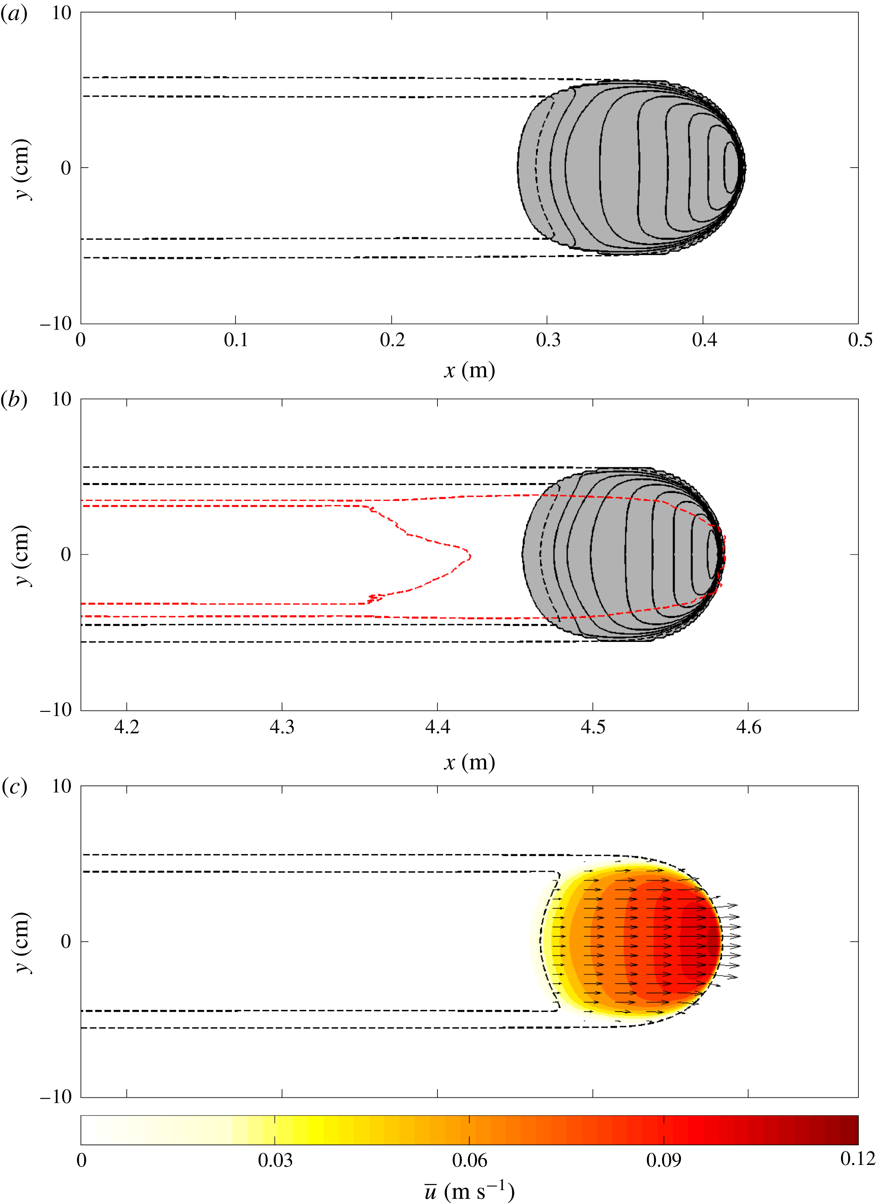
The initial condition and the computed state after 20 s are shown in figure 18(a,b). A movie is also available online (movie 7). These show that the initial and final states are virtually unchanged. The front position has moved slightly to the left, which simply implies that the imposed speed of the travelling frame was slightly greater than the actual wavespeed of the avalanche. However, there is nothing to suggest that after a longer period of computation, and the exact wavespeed of the avalanche being known, that it would not continue to propagate unchanged in this domain forever. It is rather remarkable that the presence of an erodible layer of grains can change the apparent friction of the slope and can thus produce indefinitely long run out. This is potentially very important for quantifying the risks posed by natural hazards when there are slopes covered with easily erodible material, such as in the case of snow avalanches.
Steady travelling erosion–deposition wave solution from the numerical simulation of figure 18(b) in the region
 $5~\text{cm}\leqslant x\leqslant 45$
cm, coloured by flow thickness
$5~\text{cm}\leqslant x\leqslant 45$
cm, coloured by flow thickness
 $h$
and plotted as an inclined three-dimensional surface. The
$h$
and plotted as an inclined three-dimensional surface. The
 $x$
,
$x$
,
 $y$
and
$y$
and
 $z$
axes are plotted with a 1 : 1 : 30 aspect ratio, respectively, and the dashed mesh lines are spaced 20 mm apart. The rough basal surface of the chute lies at the bottom of the blue layer. A supplementary movie of the flow is available online (movie 8).
$z$
axes are plotted with a 1 : 1 : 30 aspect ratio, respectively, and the dashed mesh lines are spaced 20 mm apart. The rough basal surface of the chute lies at the bottom of the blue layer. A supplementary movie of the flow is available online (movie 8).

The steady travelling wave solution is the three-dimensional equivalent of the two-dimensional erosion–deposition waves observed by Edwards & Gray (Reference Edwards and Gray2015). The final computed state shown in figure 18(b) compares very favourably with the experimentally observed deposit contour shown in red. The avalanche is wider and shorter than the experimental avalanche, but the quantitative comparison is reasonably good and the qualitative features of a levee and shallow trough are very close to what are observed in the simulations. One interesting feature in the experiments that one does not see in the numerical computations is that the tail of the moving part of the avalanche has a pronounced ‘V’-shape. This may be an indication that the avalanche is eroding down to different depths within the channel. To help visualize the computed wave figure 19 shows a three-dimensional surface plot of an erosion–deposition wave with an exaggerated vertical height and colour scale used to reveal the shape of the wave (in red), the trough (in blue), the levees (in yellow) and the undisturbed deposit (in green).
7 Conclusions
This paper shows that when a finite mass of carborundum particles is released on a rough plane covered with an erodible layer of the same grains, there are three qualitatively different behaviours that can be observed dependent on the slope inclination and the deposit thickness. For sufficiently shallow slopes the avalanche propagates for a finite distance before coming to rest, as one may intuitively expect (Pouliquen & Forterre Reference Pouliquen and Forterre2002). At a steeper slope angle, the avalanche has been observed to either propagate steadily with constant wavespeed and shape, or, when released on a thicker erodible layer, to accumulate additional particles (bulking) and therefore grow and accelerate. The steady travelling avalanche is the three-dimensional equivalent of the two-dimensional erosion–deposition waves observed by Edwards & Gray (Reference Edwards and Gray2015). Provided that both the static layer in front of the flow and the inclination angle do not change, this wave can travel arbitrarily long distances, which is an intriguing observation. Behind it, the wave leaves a shallow deposited trough that is flanked by levees on either side as illustrated in figure 19. Since erosion and deposition are in exact balance, the total volume of material in the levees and the trough is the same as the equivalent volume in the undisturbed layer ahead of the wave. For the growing avalanches the avalanche essentially leaves behind an eroded trough of previously mobilized material that widens with increasing downstream distance (Daerr & Douady Reference Daerr and Douady1999). Conversely, for decaying avalanches, there is net mass loss, and a channel is left behind that is elevated above the initially static deposit height and narrows with downstream distance, terminating in a static deposited head.
Given the notorious difficulty in modelling erosion–deposition problems, it is remarkable that all three of these behaviours can be modelled by combining the extended rough bed friction law of Pouliquen & Forterre (Reference Pouliquen and Forterre2002) with a two-dimensional generalization (Baker et al.
Reference Baker, Barker and Gray2016a
) of the depth-averaged
 $\unicode[STIX]{x1D707}(I)$
-rheology of Gray & Edwards (Reference Gray and Edwards2014). The theory is crude, in that the interface between the static and moving grains is not resolved in the vertical direction. Instead, the flow is either static or moving through its entire depth, which is a good approximation for the shallow erodible beds considered here. An important element of the model is that the static, dynamic and intermediate regimes in the rough bed friction law (3.15) have been modified slightly to give greater stability to static layers that form in the hysteretic region between
$\unicode[STIX]{x1D707}(I)$
-rheology of Gray & Edwards (Reference Gray and Edwards2014). The theory is crude, in that the interface between the static and moving grains is not resolved in the vertical direction. Instead, the flow is either static or moving through its entire depth, which is a good approximation for the shallow erodible beds considered here. An important element of the model is that the static, dynamic and intermediate regimes in the rough bed friction law (3.15) have been modified slightly to give greater stability to static layers that form in the hysteretic region between
 $h_{stop}$
and
$h_{stop}$
and
 $h_{start}$
. In particular, the power law transition starts at a higher Froude number
$h_{start}$
. In particular, the power law transition starts at a higher Froude number
 $\unicode[STIX]{x1D6FD}_{\star }$
than is normal and the subsequent transition between the static and dynamic states is much more gradual (
$\unicode[STIX]{x1D6FD}_{\star }$
than is normal and the subsequent transition between the static and dynamic states is much more gradual (
 $\unicode[STIX]{x1D705}=1$
) than in the original formulation (Pouliquen & Forterre Reference Pouliquen and Forterre2002) where
$\unicode[STIX]{x1D705}=1$
) than in the original formulation (Pouliquen & Forterre Reference Pouliquen and Forterre2002) where
 $\unicode[STIX]{x1D705}$
was equal to
$\unicode[STIX]{x1D705}$
was equal to
 $10^{-3}$
. The resulting model is able to capture qualitatively all of the key behaviour observed in the experiments, and the quantitative agreement is also good, even though the avalanches tends to be shorter and wider than observed. The growing, decaying and steady avalanches will stop if they flow out onto a run-out plane. The same equations can be used to compute the arrest, however, care must be taken to regularize the coefficient
$10^{-3}$
. The resulting model is able to capture qualitatively all of the key behaviour observed in the experiments, and the quantitative agreement is also good, even though the avalanches tends to be shorter and wider than observed. The growing, decaying and steady avalanches will stop if they flow out onto a run-out plane. The same equations can be used to compute the arrest, however, care must be taken to regularize the coefficient
 $\unicode[STIX]{x1D708}$
in the viscosity for angles
$\unicode[STIX]{x1D708}$
in the viscosity for angles
 $\unicode[STIX]{x1D701}<\unicode[STIX]{x1D701}_{1}$
.
$\unicode[STIX]{x1D701}<\unicode[STIX]{x1D701}_{1}$
.
Both the bulking up of snow slab avalanches through frontal ploughing (Sovilla et al.
Reference Sovilla, Sommavilla and Tomaselli2001; Sovilla & Bartelt Reference Sovilla and Bartelt2002; Sovilla et al.
Reference Sovilla, Burlando and Bartelt2006) as well as their sudden arrest in the run-out zone are strongly affected by the net erosion and deposition in the flow. In particular, the existence of an easily erodible layer confers much greater mobility to the flow than one might otherwise expect (Mangeney et al.
Reference Mangeney, Roche, Hungr, Mangold, Faccanoni and Lucas2010; Iverson et al.
Reference Iverson, Reid, Logan, LaHusen, Godt and Griswold2011) and run-out distances can be significantly enhanced. It is therefore anticipated that the relatively simple model for erosion and deposition, developed in this paper, may find important application in predicting the risk posed by a wide range of geophysical mass flows on erodible slopes. A key challenge for the future is how to determine the
 $h_{stop}$
and
$h_{stop}$
and
 $h_{start}$
curves for real geophysical materials where the fixed bed may not be clearly defined.
$h_{start}$
curves for real geophysical materials where the fixed bed may not be clearly defined.
Acknowledgements
This research was supported by NERC grants NE/E003206/1 and NE/K003011/1 as well as EPSRC grants EP/I019189/1, EP/K00428X/1 and EP/M022447/1. J.M.N.T.G. is a Royal Society Wolfson Research Merit Award holder (WM150058) and an EPSRC Established Career Fellow (EP/M022447/1). All research data supporting this publication are directly available within this publication.
Supplementary movies
Supplementary movies are available at https://doi.org/10.1017/jfm.2017.309.


 Open access