

1. Introduction
Threats of malicious or accidental release have motivated recent efforts to understand dispersion of airborne pollutants within urban areas. The pollutant can be considered to be emitted from a point source, and the emergency services need to make rapid decisions about the contaminated area, which requires rapid quantitative estimates of the dispersion. Interest in this scientific problem is also motivated by the potential health impacts of poor urban air quality, when the sources are distributed over a wide area. Dispersion in these problems is mediated by high-Reynolds-number turbulent flow through a complex array of obstacles (Fernando et al. Reference Fernando, Zajic, Di Sabatino, Dimitrova, Hedquist and Dallman2010). Turbulence itself is of course efficient at dispersion. But so too is the passage through complex geometries. In such flows the mean streamlines diverge around the obstacles, separating fluid parcels and thus dispersing passive scalar. Davidson et al. (Reference Davidson, Mylne, Jones, Phillips and Perkins1995, Reference Davidson, Snyder, Lawson and Hunt1996) have termed this process topological dispersion. So an interesting and important question in dispersion in urban areas is the relative roles of turbulence and topological dispersion.
Here we consider dispersion of steady releases from point sources in flows with a Reynolds number large enough for the flow to be fully turbulent and with no buoyancy forces. In these situations it has been found empirically that, beyond approximately 1 km from the source, conventional Gaussian plume models are effective in representing dispersion above urban areas (e.g. Briggs Reference Briggs1973; Arya Reference Arya1999), presumably because in this far field the majority of the scalar material is above the buildings, and so the plume disperses in the turbulent atmospheric boundary layer, with the urban area acting merely as a rough surface. No theory exists to predict the distance when conventional Gaussian plume models become effective, and indeed the theory developed here suggests that for some geometries it could be much further than 1 km. But over shorter length scales, when the bulk of the scalar is below the roof tops, the building geometry must surely play a role in the dispersion, and hence setting the distance when a conventional Gaussian plume model is effective. For example, the detrainment of material from the airspace between buildings into the boundary layer aloft is an important process that controls the adjustment to the far-field behaviour and is surely dependent on building geometry.
Regime diagram for dispersion through regular arrays of cuboid buildings of base
 $l\times l$
, height
$l\times l$
, height
 $h$
and separation
$h$
and separation
 $w$
. Note the logarithmic scale of the axes. The street network regime occupies the region where the buildings are sufficiently close together (
$w$
. Note the logarithmic scale of the axes. The street network regime occupies the region where the buildings are sufficiently close together (
 $h/w>1$
) and are sufficiently shallow (
$h/w>1$
) and are sufficiently shallow (
 $h/l<3$
), and the streets sufficiently long (
$h/l<3$
), and the streets sufficiently long (
 $w/l<1$
). Sparse arrays occur when the buildings are widely separated (
$w/l<1$
). Sparse arrays occur when the buildings are widely separated (
 $h/w<1$
). In the tall building regime, when
$h/w<1$
). In the tall building regime, when
 $h/l>3$
, mixing promoted at the building roofs does not penetrate down to street level. The ellipses show the range of parameters estimated for London: city centre (
$h/l>3$
, mixing promoted at the building roofs does not penetrate down to street level. The ellipses show the range of parameters estimated for London: city centre (
 $f=0.9$
), intermediate zones (
$f=0.9$
), intermediate zones (
 $f=0.7$
) and suburban surroundings (
$f=0.7$
) and suburban surroundings (
 $f=0.1$
).
$f=0.1$
).

Within the last decade, several experimental studies have reported that, sufficiently far from the source, a Gaussian plume model can work well even below the roof tops (Davidson et al. Reference Davidson, Mylne, Jones, Phillips and Perkins1995, Reference Davidson, Snyder, Lawson and Hunt1996; Macdonald, Griffiths & Cheah Reference Macdonald, Griffiths and Cheah1997; Macdonald, Griffiths & Hall Reference Macdonald, Griffiths and Hall1998; Yee & Biltoft Reference Yee and Biltoft2004; Yee et al. Reference Yee, Gailis, Hill, Hilderman and Kiel2006), provided that the plume parameters are suitably modified to account for the presence of buildings. Philips, Rossi & Iaccarino (Reference Philips, Rossi and Iaccarino2013) derive Gaussian plume parameters for an urban-like canopy using data from a large-eddy simulation. Models have also been developed for dispersion very close to the source. They are based on the air flow within individual streets, e.g. OSPM (Berkowitz Reference Berkowitz2000) and ADMS (Carruthers et al. Reference Carruthers, Edmunds, Lester, McHugh and Singles2000). Such models are typically based on a Gaussian plume that advects and disperses scalar within a simplified model of the air flow within the street. They do not consider the dispersion of the plume through intersections, and so are limited to very short distances from the source. Here our goal is to develop a modelling framework that bridges these two extremes, and quantifies dispersion from single streets through to dispersion into the boundary layer above. Such an approach is then applicable on intermediate scales, the street network scale or neighbourhood scale, which lies between the street scale and the city scale (Britter & Hanna Reference Britter and Hanna2003). We focus on the process of topological dispersion within the network of streets and the process of vertical turbulent detrainment of material from the airspace between the buildings into the boundary layer aloft. A quantitative model that accounts for these processes will be shown to provide a unified description of the near- and far-field behaviour, and in particular recover Gaussian plume behaviour within the street network sufficiently far from the source.
1.1. Controlling parameters and regimes
Urban areas are so diverse in their building geometry and density that it seems unlikely that one single approach to dispersion modelling is appropriate for all. Hence, the regime diagram shown in figure 1 is proposed here as a step towards assessing which method is appropriate to modelling dispersion in a particular urban area and to identify the parameter regime of interest in this paper. For simplicity, the diagram is formulated for a regular, aligned, array of cuboid buildings (or building blocks) of base
 $l\times l$
, height
$l\times l$
, height
 $h$
and the gaps between the buildings are of width
$h$
and the gaps between the buildings are of width
 $w$
. The streets, defined here to be the area between the buildings (including the road surface, pavement, etc.) are therefore of width
$w$
. The streets, defined here to be the area between the buildings (including the road surface, pavement, etc.) are therefore of width
 $w$
and length
$w$
and length
 $l$
. The axes on the figure are the width of the streets and the height of the buildings, both normalised on the length of the streets. We divide the diagram according to three criteria.
$l$
. The axes on the figure are the width of the streets and the height of the buildings, both normalised on the length of the streets. We divide the diagram according to three criteria.
First, consider the role of the height-to-width ratio,
 $h/w$
, of the streets. Consider first the simplified case when the mean wind is perpendicular to very long streets. Flow visualisation (e.g. Oke Reference Oke1987) shows that, when the streets are wide so that
$h/w$
, of the streets. Consider first the simplified case when the mean wind is perpendicular to very long streets. Flow visualisation (e.g. Oke Reference Oke1987) shows that, when the streets are wide so that
 $h/w<1/3$
, the buildings produce wakes that interact only weakly with the downwind building. Hence, when
$h/w<1/3$
, the buildings produce wakes that interact only weakly with the downwind building. Hence, when
 $h/w<1/3$
we have a sparse array: the building wakes interact weakly and dispersion beyond a very near-source region can be modelled by modifying Gaussian plume formulae (Hall et al.
Reference Hall, Spanton, Griffiths, Hargrave, Walker and John2001; see also Belcher et al.
Reference Belcher, Coceal, Hunt, Carruthers and Robins2013). At the other end of the range, when the streets are narrow so that
$h/w<1/3$
we have a sparse array: the building wakes interact weakly and dispersion beyond a very near-source region can be modelled by modifying Gaussian plume formulae (Hall et al.
Reference Hall, Spanton, Griffiths, Hargrave, Walker and John2001; see also Belcher et al.
Reference Belcher, Coceal, Hunt, Carruthers and Robins2013). At the other end of the range, when the streets are narrow so that
 $h/w>1$
, the recirculation region associated with the wake of the upwind building extends to the downwind building. We then have a dense array.
$h/w>1$
, the recirculation region associated with the wake of the upwind building extends to the downwind building. We then have a dense array.
Second, consider the role of the length of the street. When the flow is at angle
 ${\it\theta}$
to the street axis, there is a component
${\it\theta}$
to the street axis, there is a component
 $U\sin {\it\theta}$
across the street driving the recirculation and tending to mix pollutant uniformly across the street, and a component
$U\sin {\it\theta}$
across the street driving the recirculation and tending to mix pollutant uniformly across the street, and a component
 $U\cos {\it\theta}$
that advects pollutant along the street (DePaul & Sheih Reference DePaul and Sheih1986; Dobre et al.
Reference Dobre, Arnold, Smalley, Boddy, Barlow, Tomlin and Belcher2005). Air parcels follow helical paths. Provided the helical path has made one circuit, pollutant is mixed nearly uniformly across the width and height of the streets. For the simple case when
$U\cos {\it\theta}$
that advects pollutant along the street (DePaul & Sheih Reference DePaul and Sheih1986; Dobre et al.
Reference Dobre, Arnold, Smalley, Boddy, Barlow, Tomlin and Belcher2005). Air parcels follow helical paths. Provided the helical path has made one circuit, pollutant is mixed nearly uniformly across the width and height of the streets. For the simple case when
 ${\it\theta}\approx 45^{\circ }$
, when
${\it\theta}\approx 45^{\circ }$
, when
 $w/l<1$
the streets are probably sufficiently long that the air parcels make one circuit of their helical path before encountering the next intersection. Hence, on figure 1 we think of streets when
$w/l<1$
the streets are probably sufficiently long that the air parcels make one circuit of their helical path before encountering the next intersection. Hence, on figure 1 we think of streets when
 $w/l<1$
.
$w/l<1$
.
Third, when the buildings in the array are much taller than the streets are long, so that
 $h/l>3$
, the air space in the array is not well mixed in the vertical (Cai, Barlow & Belcher Reference Cai, Barlow and Belcher2008). In this case the array of buildings acts as a tall building canopy. Canopies of tall buildings are not catered for in operational models; indeed there is no proven methodology for attempting modelling. The porous canopy approach (e.g. Belcher, Jerram & Hunt Reference Belcher, Jerram and Hunt2003; Coceal & Belcher Reference Coceal and Belcher2004) looks to be a good possibility, but measurements are needed in sufficient detail to inform the development and validation of models. When the buildings are shorter so that
$h/l>3$
, the air space in the array is not well mixed in the vertical (Cai, Barlow & Belcher Reference Cai, Barlow and Belcher2008). In this case the array of buildings acts as a tall building canopy. Canopies of tall buildings are not catered for in operational models; indeed there is no proven methodology for attempting modelling. The porous canopy approach (e.g. Belcher, Jerram & Hunt Reference Belcher, Jerram and Hunt2003; Coceal & Belcher Reference Coceal and Belcher2004) looks to be a good possibility, but measurements are needed in sufficient detail to inform the development and validation of models. When the buildings are shorter so that
 $h/l<3$
the air is well mixed from building top down to street level (Cai et al.
Reference Cai, Barlow and Belcher2008).
$h/l<3$
the air is well mixed from building top down to street level (Cai et al.
Reference Cai, Barlow and Belcher2008).
There is therefore a regime when the streets are sufficiently narrow that
 $h/w>1$
and the buildings sufficiently short that
$h/w>1$
and the buildings sufficiently short that
 $h/l<3$
; then the helical path of air parcels spans the cavity between buildings. When, in addition, the streets are long enough that air parcels make a complete circuit of their helical path before reaching the next intersection, i.e.
$h/l<3$
; then the helical path of air parcels spans the cavity between buildings. When, in addition, the streets are long enough that air parcels make a complete circuit of their helical path before reaching the next intersection, i.e.
 $w/l<1$
, then pollutants are largely well mixed across the street (e.g. Cai et al.
Reference Cai, Barlow and Belcher2008). The urban area can then be represented as a connected network of streets which act as well-mixed boxes. We refer to this part of the parameter space on figure 1 as the street network regime, the subject of this paper.
$w/l<1$
, then pollutants are largely well mixed across the street (e.g. Cai et al.
Reference Cai, Barlow and Belcher2008). The urban area can then be represented as a connected network of streets which act as well-mixed boxes. We refer to this part of the parameter space on figure 1 as the street network regime, the subject of this paper.
What are the typical regimes in cities? The data developed by Bohnenstengel et al. (Reference Bohnenstengel, Evans, Clark and Belcher2011) for London provide an opportunity to evaluate the dispersion regimes we expect in different parts of the city. They analysed the Virtual London dataset (Evans, Hudson-Smith & Batty Reference Evans, Hudson-Smith and Batty2005) to produce maps of two measures of the building layout, namely the plan area density
 ${\it\lambda}_{p}$
and frontal area density
${\it\lambda}_{p}$
and frontal area density
 ${\it\lambda}_{f}$
, defined respectively as the plan area and frontal area occupied by buildings divided by the total area of the land on which they are located. They divided London into a grid of
${\it\lambda}_{f}$
, defined respectively as the plan area and frontal area occupied by buildings divided by the total area of the land on which they are located. They divided London into a grid of
 $1~\text{km}\times 1~\text{km}$
boxes. Within each grid box the fraction of urban land use,
$1~\text{km}\times 1~\text{km}$
boxes. Within each grid box the fraction of urban land use,
 $f$
, was determined as the ratio of urban land use to the total area. Then the frontal and plan areas of the buildings within the
$f$
, was determined as the ratio of urban land use to the total area. Then the frontal and plan areas of the buildings within the
 $1~\text{km}\times 1~\text{km}$
grid boxes were computed. Values of
$1~\text{km}\times 1~\text{km}$
grid boxes were computed. Values of
 ${\it\lambda}_{p}$
and
${\it\lambda}_{p}$
and
 ${\it\lambda}_{f}$
for each grid box were then computed by dividing the plan area and frontal area by the area of urban land use within each grid box (see figures 2 and 3 in Bohnenstengel et al.
Reference Bohnenstengel, Evans, Clark and Belcher2011).
${\it\lambda}_{f}$
for each grid box were then computed by dividing the plan area and frontal area by the area of urban land use within each grid box (see figures 2 and 3 in Bohnenstengel et al.
Reference Bohnenstengel, Evans, Clark and Belcher2011).
If we make the rough assumption that buildings in London within each
 $1~\text{km}\times 1~\text{km}$
box are uniform cuboids (as in figure 1), then the values of
$1~\text{km}\times 1~\text{km}$
box are uniform cuboids (as in figure 1), then the values of
 ${\it\lambda}_{p}$
and
${\it\lambda}_{p}$
and
 ${\it\lambda}_{f}$
from Bohnenstengel et al. (Reference Bohnenstengel, Evans, Clark and Belcher2011) can be used to estimate values for
${\it\lambda}_{f}$
from Bohnenstengel et al. (Reference Bohnenstengel, Evans, Clark and Belcher2011) can be used to estimate values for
 $w/l$
and
$w/l$
and
 $h/l$
, as follows. For cuboidal buildings with base
$h/l$
, as follows. For cuboidal buildings with base
 $l\times l$
, height
$l\times l$
, height
 $h$
and gaps between buildings, the streets, of width
$h$
and gaps between buildings, the streets, of width
 $w$
, the parameters
$w$
, the parameters
 ${\it\lambda}_{p}$
and
${\it\lambda}_{p}$
and
 ${\it\lambda}_{f}$
can be rearranged to give
${\it\lambda}_{f}$
can be rearranged to give
 $$\begin{eqnarray}\frac{h}{l}=\frac{{\it\lambda}_{f}}{{\it\lambda}_{p}},\quad \frac{w}{l}={\it\lambda}_{p}^{-1/2}-1.\end{eqnarray}$$
Now, Bohnenstengel et al. (Reference Bohnenstengel, Evans, Clark and Belcher2011) show that the fraction of urban land use,
 $f$
, decreases from high values of approximately 0.9 in the city centre to low values of approximately 0.1 in the suburban fringes. Hence, on figure 1 we show, by ellipses, the range of values of
$f$
, decreases from high values of approximately 0.9 in the city centre to low values of approximately 0.1 in the suburban fringes. Hence, on figure 1 we show, by ellipses, the range of values of
 $w/l$
and
$w/l$
and
 $h/l$
computed with this method for the city centre
$h/l$
computed with this method for the city centre
 $f=0.9$
, for
$f=0.9$
, for
 $f=0.7$
and for the suburban surroundings
$f=0.7$
and for the suburban surroundings
 $f=0.1$
. According to this approximate calculation the suburban surroundings (
$f=0.1$
. According to this approximate calculation the suburban surroundings (
 $f=0.1$
) act as a sparse array and the central region (
$f=0.1$
) act as a sparse array and the central region (
 $f=0.9$
) acts as a street network. This finding motivates further the need for a rationally based model of dispersion in the street network regime.
$f=0.9$
) acts as a street network. This finding motivates further the need for a rationally based model of dispersion in the street network regime.
1.2. Street network models of dispersion
In the street network regime, we represent the urban area as a connected network of boxes. Scalar is advected along the streets and dispersed as the network branches at intersections. Soulhac (Reference Soulhac2000) and Soulhac et al. (Reference Soulhac, Salizzoni, Cierco and Perkins2011, Reference Soulhac, Salizzoni, Mejean, Didier and Rios2012) developed the basic equations for a family of network models, together with methods for estimating the model parameters. This led to an operational dispersion model that was first applied to the city of Lyon in France. Belcher (Reference Belcher2005) reviewed our understanding of the basic processes controlling the mixing and transport through streets and intersections and further examined the foundations for a network approach. Hamlyn, Hilderman & Britter (Reference Hamlyn, Hilderman and Britter2007) constructed a network model for dispersion through an array of cubes, and showed impressive agreement with measurements made in a water channel by Hilderman & Chong (Reference Hilderman and Chong2007).
The present paper has several specific aims that build upon these previous studies. First, we develop the equations of the street network family of models from the full scalar transport equations, paying careful attention to the underlying assumptions and distinguishing the parameterisations that need to be made in this approach. A simple street network model is developed based on analysis of direct numerical simulations (DNS) through an array of cubical obstacles. Second, we show that, for a regular array of buildings, the street network model has an analytical solution that illustrates how the model parameters group together to control the concentration. The analytical solution converges onto a Gaussian plume for large distances downwind of the source, and so shows how the street network forms the initial spread of scalar through topological dispersion and vertical detrainment into the boundary layer above. Finally, the analytical solution is compared with the results of a DNS (Branford et al. Reference Branford, Coceal, Thomas and Belcher2011) and to new wind tunnel measurements. These comparisons then allow us to gain insight into, and quantify the roles of, topological dispersion and re-entrainment into the street network downstream of the source.
2. Model formulation and governing equations
2.1. Flux balance equation
When the Péclet number is high so that dispersion by advection is much stronger than diffusion by molecular processes, the equation governing dispersion of a passive scalar is
 $$\begin{eqnarray}\frac{\text{d}c}{\text{d}t}+\boldsymbol{u}\boldsymbol{\cdot }\boldsymbol{{\rm\nabla}}c=q,\end{eqnarray}$$
where
 $c$
is the instantaneous concentration,
$c$
is the instantaneous concentration,
 $\boldsymbol{u}$
is the instantaneous velocity vector and
$\boldsymbol{u}$
is the instantaneous velocity vector and
 $q$
is a source emission rate of scalar.
$q$
is a source emission rate of scalar.
Network models are based around the idea of dividing the urban area into a series of connected boxes. Within the urban canopy itself, a box can be either the volume of a street, a street segment or the volume of an intersection. The aim is to model the concentration averaged over each box. This is justified because, as argued above, the concentration within individual streets or intersections can be regarded as approximately well mixed. Each box is referenced using a pair of indices
 $(i,j)$
. Hence, define the spatially averaged concentration of the
$(i,j)$
. Hence, define the spatially averaged concentration of the
 $(i,j)$
th box to be
$(i,j)$
th box to be
 $$\begin{eqnarray}\langle c\rangle _{ij}=\frac{1}{V_{ij}}\int _{V_{ij}}c(\boldsymbol{x})\text{d}^{3}x\end{eqnarray}$$
where
 $V_{ij}$
is the volume of the
$V_{ij}$
is the volume of the
 $(i,j)$
th box. On taking the spatial average of the scalar conservation equation (2.1), we obtain
$(i,j)$
th box. On taking the spatial average of the scalar conservation equation (2.1), we obtain
 $$\begin{eqnarray}\frac{\text{d}\langle c\rangle _{ij}}{\text{d}t}+\frac{1}{V_{ij}}\int _{\partial V_{ij}}c\boldsymbol{u}\boldsymbol{\cdot }\text{d}\boldsymbol{S}=\langle q\rangle _{ij},\end{eqnarray}$$
where
 $\langle q\rangle _{ij}=(1/V_{ij})\!\int _{V_{ij}}q\,\text{d}V$
is the total source in the
$\langle q\rangle _{ij}=(1/V_{ij})\!\int _{V_{ij}}q\,\text{d}V$
is the total source in the
 $(i,j)$
th box. The total area bounding the volume
$(i,j)$
th box. The total area bounding the volume
 $V_{ij}$
is
$V_{ij}$
is
 $\partial V_{ij}$
and
$\partial V_{ij}$
and
 $\text{d}\boldsymbol{S}$
is an area element on
$\text{d}\boldsymbol{S}$
is an area element on
 $\partial V_{ij}$
. Finally, on taking an ensemble average (denoted by an overbar, with fluctuations from the average denoted by a prime) we obtain the budget equation for the ensemble-mean spatially averaged concentration through the network of boxes:
$\partial V_{ij}$
. Finally, on taking an ensemble average (denoted by an overbar, with fluctuations from the average denoted by a prime) we obtain the budget equation for the ensemble-mean spatially averaged concentration through the network of boxes:
 $$\begin{eqnarray}\frac{\text{d}C_{ij}}{\text{d}t}+\frac{1}{V_{ij}}\mathop{\sum }_{k=1}^{K}{\it\Phi}_{ij}^{k}=Q_{ij}.\end{eqnarray}$$
Here the mean concentration within the
 $(i,j)$
th box is
$(i,j)$
th box is
 $C_{ij}=\langle \overline{c}\rangle _{ij}$
, and the mean source is
$C_{ij}=\langle \overline{c}\rangle _{ij}$
, and the mean source is
 $Q_{ij}=\langle \overline{q}\rangle _{ij}$
. The
$Q_{ij}=\langle \overline{q}\rangle _{ij}$
. The
 ${\it\Phi}_{ij}^{k}$
is the ensemble-averaged flux of scalar through the
${\it\Phi}_{ij}^{k}$
is the ensemble-averaged flux of scalar through the
 $k$
th facet of the
$k$
th facet of the
 $(i,j)$
th box, which has two parts, an advective flux,
$(i,j)$
th box, which has two parts, an advective flux,
 $F_{ij}^{k}$
, and a turbulent flux,
$F_{ij}^{k}$
, and a turbulent flux,
 $f_{ij}^{k}$
:
$f_{ij}^{k}$
:
 $$\begin{eqnarray}{\it\Phi}_{ij}^{k}=F_{ij}^{k}+f_{ij}^{k}=\int _{\partial V_{ij}^{k}}(\overline{c}\,\overline{\boldsymbol{u}}+\overline{c^{\prime }\boldsymbol{u}^{\prime }})\boldsymbol{\cdot }\text{d}\boldsymbol{S}.\end{eqnarray}$$
If the spatial and ensemble average is taken of the air mass continuity equation then
 $$\begin{eqnarray}\int _{\partial V_{ij}}\boldsymbol{u}\boldsymbol{\cdot }\text{d}\boldsymbol{S}=0.\end{eqnarray}$$
Whilst (2.4) and (2.6) express conservation of air mass and scalar, they cannot be used as a prognostic model until the fluxes are parameterised.
2.2. Parameterisation of scalar fluxes
Different parameterisations of the advective and turbulent fluxes can be formulated, based on different possible assumptions and approximations. One choice of parameterisation is discussed here that is appropriate for the application we consider in this paper.
First consider the advective flux through the facet
 $\partial V_{ij}^{k}$
into or out of the
$\partial V_{ij}^{k}$
into or out of the
 $(i,j)$
th box. The advection velocity and the concentration being advected can be decoupled by an appeal to the mean value theorem
$(i,j)$
th box. The advection velocity and the concentration being advected can be decoupled by an appeal to the mean value theorem
 $$\begin{eqnarray}F_{ij}^{k}=\int _{\partial V_{ij}^{k}}\overline{c}\,\overline{\boldsymbol{u}}\boldsymbol{\cdot }\text{d}\boldsymbol{S}=C_{{\it\alpha}{\it\beta}}\int _{\partial V_{ij}^{k}}\overline{\boldsymbol{u}}\boldsymbol{\cdot }\text{d}\boldsymbol{S}\equiv C_{{\it\alpha}{\it\beta}}\,U_{ij}^{k}\,\partial V_{ij}^{k}.\end{eqnarray}$$
Here
 $C_{{\it\alpha}{\it\beta}}$
is formally equal to the concentration at some intermediate point on the facet
$C_{{\it\alpha}{\it\beta}}$
is formally equal to the concentration at some intermediate point on the facet
 $\partial V_{ij}^{k}$
. The velocity
$\partial V_{ij}^{k}$
. The velocity
 $U_{ij}^{k}$
that advects the scalar is the air velocity averaged across the facet.
$U_{ij}^{k}$
that advects the scalar is the air velocity averaged across the facet.
The main assumption we make here is that within each box the scalar is well mixed, so that spatial variations of the time-mean scalar concentration within a box are small compared with the spatial-mean concentration within that box. In the present notation this condition can be written
 $$\begin{eqnarray}\frac{\langle (\overline{c}-\langle \overline{c}\rangle )^{2}\rangle _{ij}}{\langle \overline{c}\rangle _{ij}^{2}}=\frac{\langle (\overline{c}-\langle \overline{c}\rangle )^{2}\rangle _{ij}}{(C_{ij})^{2}}\ll 1.\end{eqnarray}$$
With this assumption, the concentration
 $C_{{\it\alpha}{\it\beta}}$
in (2.7) is then approximately equal to the volume-averaged concentration in the box upwind of
$C_{{\it\alpha}{\it\beta}}$
in (2.7) is then approximately equal to the volume-averaged concentration in the box upwind of
 $\partial V_{ij}^{k}$
.
$\partial V_{ij}^{k}$
.
Second, consider the turbulent flux through the facet
 $\partial V_{ij}^{k}$
into or out of the
$\partial V_{ij}^{k}$
into or out of the
 $(i,j)$
th box. Here we model turbulent exchange so that it tends to equalise the concentrations in the boxes joined by the facet
$(i,j)$
th box. Here we model turbulent exchange so that it tends to equalise the concentrations in the boxes joined by the facet
 $\partial V_{ij}^{k}$
. Hence, the flux is proportional to the difference in concentration between the boxes,
$\partial V_{ij}^{k}$
. Hence, the flux is proportional to the difference in concentration between the boxes,
 $(C_{ij}-C_{{\it\alpha}{\it\beta}})$
, and an exchange velocity
$(C_{ij}-C_{{\it\alpha}{\it\beta}})$
, and an exchange velocity
 $E_{ij}^{k}$
, which characterises the rate toward equal concentrations. Hence,
$E_{ij}^{k}$
, which characterises the rate toward equal concentrations. Hence,
 $$\begin{eqnarray}f_{ij}^{k}=\int _{\partial V_{ij}^{k}}\overline{c^{\prime }\boldsymbol{u}^{\prime }}\boldsymbol{\cdot }\text{d}\boldsymbol{S}\equiv (C_{ij}-C_{{\it\alpha}{\it\beta}})\,E_{ij}^{k}\,\partial V_{ij}^{k},\end{eqnarray}$$
which is the finite difference equivalent of a gradient diffusion approximation.
We recognise that there are other choices for the parameterisation of the advective and turbulent fluxes; for example Soulhac (Reference Soulhac2000) modelled advective fluxes at street intersections differently (see § 4.2 below). In this sense there is a family of street network models. The aim here is to develop specific parameterisations to examine the roles of the processes in some specific situations. The parameterisations will depend on modelling assumptions and approximations, which may not hold universally. Indeed different approximations may be appropriate in different contexts. Our focus here is on point source releases in regular street networks, particularly when the streets are not too long. To test the appropriateness of the parameterisations (2.7) and (2.9) in the present context we analyse data from a DNS in a regular array of cubes.
3. Evaluation of the model assumptions using DNS data
The DNS simulated a turbulent flow and passive scalar dispersion within a regular array of cubes. Details of the computational methods used are given in Coceal et al. (Reference Coceal, Thomas, Castro and Belcher2006, Reference Coceal, Dobre, Thomas and Belcher2007) and Branford et al. (Reference Branford, Coceal, Thomas and Belcher2011). Figure 2 shows a plan view of the computational domain. For the flow, periodic boundary conditions were imposed in the horizontal directions. A free-slip boundary condition was applied at the top of the domain, and no-slip and impermeability conditions were applied on all solid surfaces. The flow was driven by a body force at an angle of 45° to the cubes. The roughness Reynolds number of the flow was
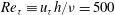 $\mathit{Re}_{{\it\tau}}\equiv u_{{\it\tau}}h/{\it\nu}=500$
, where
$\mathit{Re}_{{\it\tau}}\equiv u_{{\it\tau}}h/{\it\nu}=500$
, where
 $u_{{\it\tau}}$
is the wall friction velocity,
$u_{{\it\tau}}$
is the wall friction velocity,
 $h$
is the cube height and
$h$
is the cube height and
 ${\it\nu}$
is the kinematic viscosity. Due to the imposition of periodic boundary conditions the time-mean flow, when averaged over a sufficiently long duration, was the same within each repeating unit of the array. This implies that the advection and detrainment velocities of the street network model (2.7) and (2.9) are equal in each repeating unit of the array. The Schmidt number in the DNS was 1. A passive scalar was released from a point source near the ground (at a height of
${\it\nu}$
is the kinematic viscosity. Due to the imposition of periodic boundary conditions the time-mean flow, when averaged over a sufficiently long duration, was the same within each repeating unit of the array. This implies that the advection and detrainment velocities of the street network model (2.7) and (2.9) are equal in each repeating unit of the array. The Schmidt number in the DNS was 1. A passive scalar was released from a point source near the ground (at a height of
 $z=0.0625h$
) within the array at locations denoted by crosses in figure 2. The concentration field from the DNS was averaged over a sufficiently long time to give stable statistics then ensemble-averaged over the set of sources. It was then volume-averaged over the volumes of the streets and intersections within the array to give an output analogous to that of the network model.
$z=0.0625h$
) within the array at locations denoted by crosses in figure 2. The concentration field from the DNS was averaged over a sufficiently long time to give stable statistics then ensemble-averaged over the set of sources. It was then volume-averaged over the volumes of the streets and intersections within the array to give an output analogous to that of the network model.
Plan view of the computational domain in the DNS of Branford et al. (Reference Branford, Coceal, Thomas and Belcher2011). The arrow denotes the mean wind direction (45° to the cube faces) and crosses show the source locations; the height of the sources is at
 $z=0.0625h$
, where
$z=0.0625h$
, where
 $h$
is the cube height.
$h$
is the cube height.

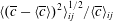
Figure 3 shows a plot of the spatial root mean square (r.m.s.) fluctuation of concentration as a fraction of the spatial mean within each box downstream of the source,
 $\langle (\overline{c}-\langle \overline{c}\rangle )^{2}\rangle _{ij}^{1/2}/\langle \overline{c}\rangle _{ij}$
; the ratio is required to be small for the well-mixed approximation to hold, as in (2.8). The source is located at
$\langle (\overline{c}-\langle \overline{c}\rangle )^{2}\rangle _{ij}^{1/2}/\langle \overline{c}\rangle _{ij}$
; the ratio is required to be small for the well-mixed approximation to hold, as in (2.8). The source is located at
 $(3.5h,3.5h)$
. The plot shows that this ratio is generally under 0.3 in the middle of the plume, although it can be larger (of order 0.5) in the very near field and on plume edges. Higher values that occur further out along the edges are probably due to the very small values of mean concentration
$(3.5h,3.5h)$
. The plot shows that this ratio is generally under 0.3 in the middle of the plume, although it can be larger (of order 0.5) in the very near field and on plume edges. Higher values that occur further out along the edges are probably due to the very small values of mean concentration
 $\langle \overline{c}\rangle _{ij}$
in those locations. The only box where there is a substantially higher value (approximately 3.8) is the one in which the source is located, not surprisingly. This demonstrates that the well-mixed assumption is a reasonable approximation for this geometry and wind direction. That this is so is an important simplifying assumption; however, it may not necessarily hold in other cases. Hence, the appropriateness of this assumption should be examined critically before it is applied in different contexts.
$\langle \overline{c}\rangle _{ij}$
in those locations. The only box where there is a substantially higher value (approximately 3.8) is the one in which the source is located, not surprisingly. This demonstrates that the well-mixed assumption is a reasonable approximation for this geometry and wind direction. That this is so is an important simplifying assumption; however, it may not necessarily hold in other cases. Hence, the appropriateness of this assumption should be examined critically before it is applied in different contexts.
Ensemble-averaged spatial r.m.s. of concentration as a fraction of spatially averaged concentration in each box
 $\langle (\overline{c}-\langle \overline{c}\rangle )^{2}\rangle _{ij}^{1/2}/\langle \overline{c}\rangle _{ij}$
. The source is located at
$\langle (\overline{c}-\langle \overline{c}\rangle )^{2}\rangle _{ij}^{1/2}/\langle \overline{c}\rangle _{ij}$
. The source is located at
 $(3.5h,3.5h)$
. The value in the source box is 3.8.
$(3.5h,3.5h)$
. The value in the source box is 3.8.

Wood et al. (Reference Wood, Arnold, Balogun, Barlow, Belcher, Britter, Cheng, Dobre, Lingard, Martin, Neophytou, Petersson, Robins, Shallcross, Smalley, Tate, Tomlin and White2009) reported scalar being dispersed upwind of the mean wind direction in the DAPPLE project measurements of dispersion in Central London. To diagnose the extent of ‘upwind’ dispersion here, the DNS data was used to compute the mean concentration in the four streets around the intersection where the release occurs. The mean concentration in the streets just upwind of the release is 20 times smaller than the concentration in the streets just downwind of the release. We conclude that, at least in this geometry, most of the upwind dispersion takes place within the box where the source is located, and upwind transport of material into boxes upstream of the release can be neglected.
It is instructive to compare the contributions to the scalar flux from the advective and turbulent components. Figure 4 shows the fraction of the horizontal components of the advective,
 $\langle \overline{c}\,\overline{u_{i}}\rangle$
, and turbulent,
$\langle \overline{c}\,\overline{u_{i}}\rangle$
, and turbulent,
 $\langle \overline{c^{\prime }u_{i}^{\prime }}\rangle$
, fluxes in intersections and streets in the centre of the plume. It is evident that the turbulent flux represents only a small fraction of the total horizontal flux (
$\langle \overline{c^{\prime }u_{i}^{\prime }}\rangle$
, fluxes in intersections and streets in the centre of the plume. It is evident that the turbulent flux represents only a small fraction of the total horizontal flux (
 $\langle \overline{cu_{i}}\rangle$
) within the array. Averaged over the whole domain, the mean horizontal advective flux is 99 % of the total flux. Wind tunnel measurements by Carpentieri, Hayden & Robins (Reference Carpentieri, Hayden and Robins2012) on a scale model of the DAPPLE site in Central London (Wood et al.
Reference Wood, Arnold, Balogun, Barlow, Belcher, Britter, Cheng, Dobre, Lingard, Martin, Neophytou, Petersson, Robins, Shallcross, Smalley, Tate, Tomlin and White2009) confirm the above conclusions. Five intersections around Marylebone Road were examined in a wind from an angle of approximately 51° to Marylebone Road. Contributions from turbulent fluxes were typically less than 3 % of the total, with a maximum of 8 %. The one extreme case of 28 % was found to be at a location with very high turbulence levels.
$\langle \overline{cu_{i}}\rangle$
) within the array. Averaged over the whole domain, the mean horizontal advective flux is 99 % of the total flux. Wind tunnel measurements by Carpentieri, Hayden & Robins (Reference Carpentieri, Hayden and Robins2012) on a scale model of the DAPPLE site in Central London (Wood et al.
Reference Wood, Arnold, Balogun, Barlow, Belcher, Britter, Cheng, Dobre, Lingard, Martin, Neophytou, Petersson, Robins, Shallcross, Smalley, Tate, Tomlin and White2009) confirm the above conclusions. Five intersections around Marylebone Road were examined in a wind from an angle of approximately 51° to Marylebone Road. Contributions from turbulent fluxes were typically less than 3 % of the total, with a maximum of 8 %. The one extreme case of 28 % was found to be at a location with very high turbulence levels.
Mean (filled symbols) and turbulent (empty symbols) horizontal fluxes as a fraction of the total flux: circles, intersections; squares and triangles, streets.

Here we therefore make the simplification that the horizontal fluxes in the street network can be modelled by a purely advective component, and that the turbulent component can be neglected. The results shown here are for an oblique flow direction of 45° to the streets. This approximation will be expected to break down when the wind is closely aligned to the streets (just how closely is difficult to quantify in the absence of relevant data). In the DAPPLE tracer experiments the wind direction was less than 10° in only 10 % of the 60 tracer experiments.
In contrast to the horizontal fluxes, the vertical flux through the top of the array is dominated by the turbulent component
 $\langle \overline{c^{\prime }w^{\prime }}\rangle$
, with the advective component
$\langle \overline{c^{\prime }w^{\prime }}\rangle$
, with the advective component
 $\langle \overline{c}\,\overline{w}\rangle$
comprising around 10 % of the total vertical flux
$\langle \overline{c}\,\overline{w}\rangle$
comprising around 10 % of the total vertical flux
 $\langle \overline{cw}\rangle$
in the near field (not shown here). Further away from the source the comparison is more ambiguous because there is little net vertical exchange across the top of the array. Hence, the vertical flux through the top can be modelled as a purely turbulent process, at least in this regular network composed of buildings of uniform height. This approximation would be expected to be less appropriate if the array comprises buildings of unequal heights.
$\langle \overline{cw}\rangle$
in the near field (not shown here). Further away from the source the comparison is more ambiguous because there is little net vertical exchange across the top of the array. Hence, the vertical flux through the top can be modelled as a purely turbulent process, at least in this regular network composed of buildings of uniform height. This approximation would be expected to be less appropriate if the array comprises buildings of unequal heights.
Equipped with these simplifying approximations, we are now ready to proceed with the development of the street network model.
4. Specification of the model for a regular street network
The processes captured in the network model described in (2.4), (2.7) and (2.9) are now illustrated for dispersion through a regular, aligned and extensive array of cuboidal buildings (or building blocks) from a single steady source at an intersection (the results can be readily extended to arbitrary source distributions by linear superposition). This simplified geometry illustrates many of the important processes, whilst allowing the following simplifications.
-
(a) Since the geometry is regular, the geometric term
 $\partial V_{ij}^{k}/V_{ij}$
, which appears when the flux parameterisations (2.7) and (2.9) are inserted into (2.4), is independent of
$i$
and
$j$
. The streets are taken to be of width
$w_{x}$
and
$w_{y}$
and of length
$l_{x}$
and
$l_{y}$
in the
$x$
and
$y$
directions, and the buildings are of height
$h$
.
$\partial V_{ij}^{k}/V_{ij}$
, which appears when the flux parameterisations (2.7) and (2.9) are inserted into (2.4), is independent of
$i$
and
$j$
. The streets are taken to be of width
$w_{x}$
and
$w_{y}$
and of length
$l_{x}$
and
$l_{y}$
in the
$x$
and
$y$
directions, and the buildings are of height
$h$
. -
(b) With the periodic horizontal boundary conditions, the time-mean velocity field within the building array is regular in the sense that the time-mean velocity field is identical in each repeating unit of the array (although the instantaneous velocity field is not). This means that the
$U_{ij}^{k}$
and
$E_{ij}^{k}$
, which appear in the flux parameterisations (2.7) and (2.9), are independent of
$i$
and
$j$
. Hence, so are the advection velocities
$U_{I}$
and
$U_{S}$
and the exchange velocities
$E_{I}$
and
$E_{S}$
in the intersections and streets respectively (see figures 5 and 6). There is no requirement for the velocities
$U_{I}$
and
$U_{S}$
to be the same, nor for
$E_{I}$
and
$E_{S}$
to be the same.


Flux balance at a street oriented in the
 $x$
direction. The street gains scalar flux
$x$
direction. The street gains scalar flux
 ${\it\Phi}_{I}$
from the intersection upstream, loses flux
${\it\Phi}_{I}$
from the intersection upstream, loses flux
 ${\it\Phi}_{S}$
by advection into the intersection downstream, and loses flux
${\it\Phi}_{S}$
by advection into the intersection downstream, and loses flux
 ${\it\Phi}_{V}$
by detrainment into the air above. The advection velocities into and out of the street are
${\it\Phi}_{V}$
by detrainment into the air above. The advection velocities into and out of the street are
 $U_{I}$
and
$U_{I}$
and
 $U_{S}$
respectively;
$U_{S}$
respectively;
 $W_{S}$
and
$W_{S}$
and
 $E_{S}$
are the vertical advection and turbulence exchange velocities out of the street, respectively.
$E_{S}$
are the vertical advection and turbulence exchange velocities out of the street, respectively.

Flux balance at a street intersection. The intersection gains scalar fluxes
 ${\it\Phi}_{ij}^{1}$
and
${\it\Phi}_{ij}^{1}$
and
 ${\it\Phi}_{ij}^{2}$
by advection from the streets upstream, loses fluxes
${\it\Phi}_{ij}^{2}$
by advection from the streets upstream, loses fluxes
 ${\it\Phi}_{ij}^{3}$
and
${\it\Phi}_{ij}^{3}$
and
 ${\it\Phi}_{ij}^{4}$
by advection into the streets downstream, and loses flux
${\it\Phi}_{ij}^{4}$
by advection into the streets downstream, and loses flux
 ${\it\Phi}_{ij}^{5}$
by detrainment into the air above. The advection velocities into the intersection are
${\it\Phi}_{ij}^{5}$
by detrainment into the air above. The advection velocities into the intersection are
 $U_{S}$
and
$U_{S}$
and
 $V_{S}$
and the advection velocities out of the intersection are
$V_{S}$
and the advection velocities out of the intersection are
 $U_{I}$
and
$U_{I}$
and
 $V_{I}$
;
$V_{I}$
;
 $W_{I}$
and
$W_{I}$
and
 $E_{I}$
are the vertical advection and turbulence exchange velocities out of the intersection, respectively.
$E_{I}$
are the vertical advection and turbulence exchange velocities out of the intersection, respectively.

As a further simplification, we compute the steady-state concentration produced by steady sources, so that
 $\text{d}C_{ij}/\text{d}t$
in (2.4) can be ignored, and
$\text{d}C_{ij}/\text{d}t$
in (2.4) can be ignored, and
 $C_{ij}$
can be interpreted as a time average. The incorporation of unsteady sources presents no fundamental problem, when
$C_{ij}$
can be interpreted as a time average. The incorporation of unsteady sources presents no fundamental problem, when
 $C_{ij}$
should be interpreted as an ensemble average.
$C_{ij}$
should be interpreted as an ensemble average.
With these simplifications, we shall first derive the governing equations for the steady state concentration in the street network, then show that analytical solutions exist.
4.1. Flux balance for a street
Consider first the flux balance in a street. The street geometry and fluxes are sketched in figure 5 for a street oriented in the
 $x$
direction (similar equations apply for a street oriented in the
$x$
direction (similar equations apply for a street oriented in the
 $y$
direction). Since the velocities
$y$
direction). Since the velocities
 $U_{I}$
and
$U_{I}$
and
 $U_{S}$
could be different we need to accommodate vertical advection even in this simple geometry. Hence, consider first the conservation of air mass (2.6) within a street of length
$U_{S}$
could be different we need to accommodate vertical advection even in this simple geometry. Hence, consider first the conservation of air mass (2.6) within a street of length
 $l$
and width
$l$
and width
 $w$
, which is given by
$w$
, which is given by
 $$\begin{eqnarray}hwU_{I}=hwU_{S}+lwW_{S},\end{eqnarray}$$
where
 $U_{I}$
is the advection speed out of the intersection into the entrance of the street,
$U_{I}$
is the advection speed out of the intersection into the entrance of the street,
 $U_{S}$
is the advection speed out of the end of the street and
$U_{S}$
is the advection speed out of the end of the street and
 $W_{S}$
is the average vertical wind speed out of the top of the street. Consider now the flux of concentration (2.4), which under the present conditions reduces to a balance between the flux into and the fluxes out of the street (assuming no sources are present in the street), namely
$W_{S}$
is the average vertical wind speed out of the top of the street. Consider now the flux of concentration (2.4), which under the present conditions reduces to a balance between the flux into and the fluxes out of the street (assuming no sources are present in the street), namely
 $$\begin{eqnarray}{\it\Phi}_{I}+{\it\Phi}_{S}+{\it\Phi}_{V}=0.\end{eqnarray}$$
On using the definitions of the fluxes (2.5), (2.7) and (2.9), and recalling that we assume that horizontal advective fluxes within the building canopy dominate over the turbulent fluxes, these terms become:
 ${\it\Phi}_{I}=-hw\,U_{I}C_{I}$
, which is the flux into the street coming from the upstream intersection (
${\it\Phi}_{I}=-hw\,U_{I}C_{I}$
, which is the flux into the street coming from the upstream intersection (
 $C_{I}$
is the concentration coming into the street out of the intersection); and
$C_{I}$
is the concentration coming into the street out of the intersection); and
 ${\it\Phi}_{S}=hwU_{S}C_{S}$
, which is the flux out of the end of the street, where
${\it\Phi}_{S}=hwU_{S}C_{S}$
, which is the flux out of the end of the street, where
 $C_{S}$
is the average concentration within the street. The vertical flux out of the streets is driven by both advective and turbulent fluxes, and is given by
$C_{S}$
is the average concentration within the street. The vertical flux out of the streets is driven by both advective and turbulent fluxes, and is given by
 ${\it\Phi}_{V}=wl\{E_{S}(C_{S}-D_{S})+W_{S}C_{S}\}$
, where
${\it\Phi}_{V}=wl\{E_{S}(C_{S}-D_{S})+W_{S}C_{S}\}$
, where
 $D_{S}$
is the concentration above the street,
$D_{S}$
is the concentration above the street,
 $E_{S}$
is the turbulence exchange velocity and
$E_{S}$
is the turbulence exchange velocity and
 $W_{S}$
is the vertical advection speed out of the top of the street determined by (4.1). Here we have assumed that
$W_{S}$
is the vertical advection speed out of the top of the street determined by (4.1). Here we have assumed that
 $W_{S}$
is positive, so that the mean vertical flux results in a net transfer of material from the street into the layer above; if
$W_{S}$
is positive, so that the mean vertical flux results in a net transfer of material from the street into the layer above; if
 $W_{S}$
is negative, the last term in
$W_{S}$
is negative, the last term in
 ${\it\Phi}_{V}$
should be replaced by a term involving
${\it\Phi}_{V}$
should be replaced by a term involving
 $W_{S}D_{S}$
instead. On substituting these expressions into (4.2) and rearranging yields
$W_{S}D_{S}$
instead. On substituting these expressions into (4.2) and rearranging yields
 $$\begin{eqnarray}C_{S}=\frac{hU_{I}}{hU_{S}+l(E_{S}+W_{S})}C_{I}+\frac{lE_{S}}{hU_{S}+l(E_{S}+W_{S})}D_{S}\equiv rC_{I}+eD_{S},\end{eqnarray}$$
which defines the dimensionless coefficients
 $r$
and
$r$
and
 $e$
. The last result shows that, if the concentration above the street
$e$
. The last result shows that, if the concentration above the street
 $D_{S}$
is negligible, the mean vertical advection
$D_{S}$
is negligible, the mean vertical advection
 $W_{S}$
can be absorbed into an effective vertical exchange velocity
$W_{S}$
can be absorbed into an effective vertical exchange velocity
 $E_{S}$
.
$E_{S}$
.
If the street is long, then it is no longer appropriate to assume that the concentration is well mixed along its whole length, because scalar is detrained into the boundary layer leading to a systematic reduction in concentration along the street length. In this case the street can be separated into shorter segments that account for the detrainment. A model for this process is proposed in appendix A, but is not pursued further here.
4.2. Flux balance for an intersection
Consider now the four-way intersection that occurs in this simplified geometry, see figure 6. Equation (2.6) for conservation of air evaluated for the intersection gives
 $$\begin{eqnarray}hw_{y}U_{S}+hw_{x}V_{S}=hw_{y}U_{I}+hw_{x}V_{I}+w_{x}w_{y}W_{I},\end{eqnarray}$$
where the
 $U$
and
$U$
and
 $V$
characterise advection in the
$V$
characterise advection in the
 $x$
and
$x$
and
 $y$
directions,
$y$
directions,
 $w_{x}$
and
$w_{x}$
and
 $w_{y}$
are the width of streets and
$w_{y}$
are the width of streets and
 $h$
is the height of the buildings. Finally
$h$
is the height of the buildings. Finally
 $W_{I}$
is the mean vertical velocity across the top of the intersection.
$W_{I}$
is the mean vertical velocity across the top of the intersection.
The flux balance for concentration (2.4), including the possibility of a source within the intersection, yields
 $$\begin{eqnarray}\frac{1}{hw_{x}w_{y}}\left({\it\Phi}_{ij}^{1}+{\it\Phi}_{ij}^{2}+{\it\Phi}_{ij}^{3}+{\it\Phi}_{ij}^{4}+{\it\Phi}_{ij}^{5}\right)=Q_{ij},\end{eqnarray}$$
where the factor in front of the left-hand side is just the reciprocal of the volume of the intersection.
The fluxes at the intersections have been parameterised differently in different network models (Soulhac Reference Soulhac2000; Belcher Reference Belcher2005; Hamlyn et al.
Reference Hamlyn, Hilderman and Britter2007). As discussed in § 2.2, we assume here that the concentration within the intersection is well mixed. Hence, air with concentrations equal to the concentration at the end of each of the incoming streets is advected into the intersection, it then becomes well mixed in the intersection, and well-mixed concentration is both detrained into the boundary layer above and advected along the outgoing streets. Hamlyn et al. (Reference Hamlyn, Hilderman and Britter2007) also make this approximation, albeit implicitly. Finally, note a small refinement to the notation: the intersections are indexed using
 $(i,j)$
and the streets between them with half indices, such that
$(i,j)$
and the streets between them with half indices, such that
 $i+1/2$
is the street between the
$i+1/2$
is the street between the
 $i$
th and
$i$
th and
 $(i+1)$
th intersections. Accounting for these two points, the four fluxes
$(i+1)$
th intersections. Accounting for these two points, the four fluxes
 ${\it\Phi}_{1}$
to
${\it\Phi}_{1}$
to
 ${\it\Phi}_{4}$
, which are sketched in figure 6, are advective fluxes, whereas the vertical flux
${\it\Phi}_{4}$
, which are sketched in figure 6, are advective fluxes, whereas the vertical flux
 ${\it\Phi}_{5}$
is a combination of advective and turbulent fluxes:
${\it\Phi}_{5}$
is a combination of advective and turbulent fluxes:
 $$\begin{eqnarray}\displaystyle & {\it\Phi}_{ij}^{1}=-hw_{y}U_{S}C_{i-1/2,j}=-hw_{y}U_{S}\{rC_{i-1,j}+eD_{i-(1/2),j}\}, & \displaystyle\end{eqnarray}$$
 $$\begin{eqnarray}\displaystyle & {\it\Phi}_{ij}^{2}=-hw_{x}V_{S}C_{i,j-1/2}=-hw_{x}V_{S}\{sC_{i,j-1}+fD_{i,j-(1/2)}\}, & \displaystyle\end{eqnarray}$$
 $$\begin{eqnarray}\displaystyle & {\it\Phi}_{ij}^{3}=hw_{y}U_{I}C_{i,j}, & \displaystyle\end{eqnarray}$$
 $$\begin{eqnarray}\displaystyle & {\it\Phi}_{ij}^{4}=hw_{x}V_{I}C_{i,j}, & \displaystyle\end{eqnarray}$$
 $$\begin{eqnarray}\displaystyle & {\it\Phi}_{ij}^{5}=w_{x}w_{y}\{E_{I}(C_{i,j}-D_{i,j})+W_{I}C_{i,j}\}. & \displaystyle\end{eqnarray}$$
 $C_{i-1,j}$
.) The second step in the expressions for
$C_{i-1,j}$
.) The second step in the expressions for
 ${\it\Phi}_{ij}^{1}$
and
${\it\Phi}_{ij}^{1}$
and
 ${\it\Phi}_{ij}^{2}$
is made using the result (4.3) for the street;
${\it\Phi}_{ij}^{2}$
is made using the result (4.3) for the street;
 $s$
and
$s$
and
 $f$
are defined in accordance with (4.3) as the counterparts of
$f$
are defined in accordance with (4.3) as the counterparts of
 $r$
and
$r$
and
 $e$
for streets in the
$e$
for streets in the
 $y$
direction. As remarked in relation for the vertical flux over streets, the last term in
$y$
direction. As remarked in relation for the vertical flux over streets, the last term in
 ${\it\Phi}_{ij}^{5}$
assumes the mean flux over an intersection to be upward. Treating a downward mean flux (when
${\it\Phi}_{ij}^{5}$
assumes the mean flux over an intersection to be upward. Treating a downward mean flux (when
 $W_{I}$
is negative) involves a straightforward modification that amounts to the introduction of modified effective vertical transfer velocities in the final equations presented below. For an array composed of buildings of uniform height, as in the examples considered in this paper (see § 6), it is reasonable to assume that
$W_{I}$
is negative) involves a straightforward modification that amounts to the introduction of modified effective vertical transfer velocities in the final equations presented below. For an array composed of buildings of uniform height, as in the examples considered in this paper (see § 6), it is reasonable to assume that
 $W_{S}$
and
$W_{S}$
and
 $W_{I}$
are small compared with
$W_{I}$
are small compared with
 $E_{S}$
and
$E_{S}$
and
 $E_{I}$
and can therefore be neglected. Hence, we do not explicitly consider the case when
$E_{I}$
and can therefore be neglected. Hence, we do not explicitly consider the case when
 $W_{S}$
and
$W_{S}$
and
 $W_{I}$
are negative here.
$W_{I}$
are negative here.
On substituting these flux relations into the flux balance at the
 $(i,j)$
th intersection (4.5), and re-arranging, we obtain an expression for the concentration:
$(i,j)$
th intersection (4.5), and re-arranging, we obtain an expression for the concentration:
 $$\begin{eqnarray}C_{i,j}={\it\alpha}\{\,pC_{i-1,j}+(1-p)C_{i,j-1}\}+{\it\beta}D_{i,j}+{\it\gamma}D_{i-1/2,j}+{\it\delta}D_{i,j-1/2}+S_{i,j}.\end{eqnarray}$$
The concentration within the
 $(i,j)$
th intersection,
$(i,j)$
th intersection,
 $C_{i,j}$
, is thus directly coupled to the concentration in the upwind intersections,
$C_{i,j}$
, is thus directly coupled to the concentration in the upwind intersections,
 $C_{i-1,j}$
and
$C_{i-1,j}$
and
 $C_{i,j-1}$
, and to the concentration above,
$C_{i,j-1}$
, and to the concentration above,
 $D_{i,j},D_{i-1/2,j}$
and
$D_{i,j},D_{i-1/2,j}$
and
 $D_{i,j-1/2}$
. The
$D_{i,j-1/2}$
. The
 $D$
terms arise due to re-entrainment of material into streets and intersections. In (4.11) the dimensionless factors
$D$
terms arise due to re-entrainment of material into streets and intersections. In (4.11) the dimensionless factors
 $p,{\it\alpha},{\it\beta},{\it\gamma}$
and
$p,{\it\alpha},{\it\beta},{\it\gamma}$
and
 ${\it\delta}$
are given by
${\it\delta}$
are given by
 $$\begin{eqnarray}p=\frac{rhw_{y}U_{S}}{rhw_{y}U_{S}+shw_{x}V_{S}},\end{eqnarray}$$
which is the plume direction parameter, the fraction of scalar advected out of an intersection along the
 $x$
direction, so that
$x$
direction, so that
 $(1-p)$
is the fraction advected along the
$(1-p)$
is the fraction advected along the
 $y$
direction;
$y$
direction;
 $$\begin{eqnarray}{\it\alpha}=\frac{rhw_{y}U_{S}+shw_{x}V_{S}}{hw_{y}U_{I}+hw_{x}V_{I}+w_{x}w_{y}(E_{I}+W_{I})},\end{eqnarray}$$
which is the transmission parameter, the fraction of scalar transmitted through a street and intersection, so that
 $(1-{\it\alpha})$
is the fraction of scalar detrained into the boundary layer above as it passes through a street and intersection unit;
$(1-{\it\alpha})$
is the fraction of scalar detrained into the boundary layer above as it passes through a street and intersection unit;
 $$\begin{eqnarray}{\it\beta}=\frac{w_{x}w_{y}E_{I}}{hw_{y}U_{I}+hw_{x}V_{I}+w_{x}w_{y}(E_{I}+W_{I})},\end{eqnarray}$$
which is the turbulent flux of mass exchanged with the boundary layer above as a fraction of the total exchange of mass out of the intersection; and
 $$\begin{eqnarray}\displaystyle & \displaystyle {\it\gamma}=\frac{ehw_{y}U_{S}}{hw_{y}U_{I}+hw_{x}V_{I}+w_{x}w_{y}(E_{I}+W_{I})}, & \displaystyle\end{eqnarray}$$
 $$\begin{eqnarray}\displaystyle & \displaystyle {\it\delta}=\frac{fhw_{x}V_{S}}{hw_{y}U_{I}+hw_{x}V_{I}+w_{x}w_{y}(E_{I}+W_{I})}, & \displaystyle\end{eqnarray}$$
 $e$
and
$e$
and
 $f$
factors) and the advective flux from the street into the intersection normalised on the total flux out of the intersection.
$f$
factors) and the advective flux from the street into the intersection normalised on the total flux out of the intersection.
The last term
 $S_{i,j}$
in (4.11), which has dimensions of concentration, is given by
$S_{i,j}$
in (4.11), which has dimensions of concentration, is given by
 $$\begin{eqnarray}S_{i,j}=\frac{hw_{x}w_{y}Q_{i,j}}{hw_{y}U_{I}+hw_{x}V_{I}+w_{x}w_{y}(E_{I}+W_{I})},\end{eqnarray}$$
which is the source strength integrated over the volume of the intersection and normalised on the total exchange of mass out of the intersection.
Soulhac (Reference Soulhac2000) and Soulhac et al. (Reference Soulhac, Garbero, Salizzoni, Mejean and Perkins2009) have treated the flux balance at intersections differently. Rather than assuming that the intersection causes the concentration to become a well-mixed combination of the incoming concentrations, he assumes that the flux in the outgoing streets is a linear combination of the fluxes in the incoming streets. For example, the flux
 ${\it\Phi}_{i,j}^{3}$
leaving the intersection is computed as a linear combination of the two incoming streets. In addition, a vertical flux from the intersection into the boundary layer aloft is computed in the same ratio as the horizontal fluxes. This model requires more parameters, representing the linear weights, to be specified, and at the present time has not been shown to be superior. Hence, we use the simpler well-mixed approximation here. It must be emphasised, however, that the specific model that results from this assumption is just one of a family of network models.
${\it\Phi}_{i,j}^{3}$
leaving the intersection is computed as a linear combination of the two incoming streets. In addition, a vertical flux from the intersection into the boundary layer aloft is computed in the same ratio as the horizontal fluxes. This model requires more parameters, representing the linear weights, to be specified, and at the present time has not been shown to be superior. Hence, we use the simpler well-mixed approximation here. It must be emphasised, however, that the specific model that results from this assumption is just one of a family of network models.
5. Solution in the neighbourhood of a single source in a regular street network
Near to the source, the majority of the scalar is below roof level, within the street network, and the concentration in the boundary layer above the buildings is much smaller, i.e.
 $C_{i,j}\gg D_{i,j}$
. With this condition (4.11) simplifies to
$C_{i,j}\gg D_{i,j}$
. With this condition (4.11) simplifies to
 $$\begin{eqnarray}C_{i,j}={\it\alpha}\{pC_{i-1,j}+(1-p)C_{i,j-1}\}+S_{i,j}.\end{eqnarray}$$
When furthermore there is a single source
 $S$
at
$S$
at
 $(i,j)=(0,0)$
, the solution is
$(i,j)=(0,0)$
, the solution is
 $$\begin{eqnarray}C_{i,j}={\it\alpha}^{i+j}\,\binom{i+j}{j}\,p^{i}\,(1-p)^{j}\,S.\end{eqnarray}$$
This solution applies only in the near field of the source, when the mass of scalar below roof level is much larger than the mass above roof level. The derivation of the solution and its properties are examined next.
5.1. Interpretation of the solution
The solution (5.2) can be obtained using the method of generating functions (Wilf Reference Wilf1994), see appendix B, which can be generalised to more complex street networks; it is also straightforward to develop a proof by induction. For the simple case considered here, however, the solution can be motivated heuristically.
Consider figure 7, which shows a schematic of the dispersion through this network of streets. The solution can be seen more easily if the network is relabelled in terms of
 $n$
, the number of intersections traversed, and
$n$
, the number of intersections traversed, and
 $k$
numbered from the far most position reachable in the array, as shown in figure 7. Then
$k$
numbered from the far most position reachable in the array, as shown in figure 7. Then
 $(n,k)$
and
$(n,k)$
and
 $(i,j)$
are related by
$(i,j)$
are related by
 $$\begin{eqnarray}n=i+j,\quad k=j.\end{eqnarray}$$
Ignore for the moment the loss due to detrainment into the boundary layer above. Then it is clear from figure 7 that at the
 $(n,k)$
intersection an air parcel must have traversed
$(n,k)$
intersection an air parcel must have traversed
 $n$
intersections and made
$n$
intersections and made
 $k$
turns to the left at intersections and
$k$
turns to the left at intersections and
 $n-k$
turns to the right. It does not matter in which order the turns are made, and so the total number of routes to position
$n-k$
turns to the right. It does not matter in which order the turns are made, and so the total number of routes to position
 $(n,k)$
is the binomial coefficient
$(n,k)$
is the binomial coefficient
 $n$
choose
$n$
choose
 $k$
, written here
$k$
, written here
 $\binom{n}{k}$
. The concentration is diluted by a factor
$\binom{n}{k}$
. The concentration is diluted by a factor
 $1-p$
for a left turn and a factor
$1-p$
for a left turn and a factor
 $p$
for a right turn. The concentration after
$p$
for a right turn. The concentration after
 $n$
intersections then varies along the
$n$
intersections then varies along the
 $k$
direction as a binomial distribution of power
$k$
direction as a binomial distribution of power
 $n$
. As mentioned following (4.13), passage through one street and intersection leads to a fraction
$n$
. As mentioned following (4.13), passage through one street and intersection leads to a fraction
 ${\it\alpha}$
of the concentration being lost to detrainment. Hence, after
${\it\alpha}$
of the concentration being lost to detrainment. Hence, after
 $n$
intersections a fraction
$n$
intersections a fraction
 ${\it\alpha}^{n}$
has been lost. Since detrainment into the above air and branching through the network are independent processes, the concentration at
${\it\alpha}^{n}$
has been lost. Since detrainment into the above air and branching through the network are independent processes, the concentration at
 $(n,k)$
is then the product of the loss to the boundary layer above, the lateral spread and the original source:
$(n,k)$
is then the product of the loss to the boundary layer above, the lateral spread and the original source:
 $$\begin{eqnarray}C_{n,k}={\it\alpha}^{n}\times \binom{n}{k}p^{n-k}(1-p)^{k}\times S,\end{eqnarray}$$
which is identical to (5.2).
Schematic of dispersion through a street network. The nodes represent intersections and the connecting branches represent streets. The indices
 $i$
and
$i$
and
 $j$
locate the nodes in orthogonal directions. Alternatively, indices
$j$
locate the nodes in orthogonal directions. Alternatively, indices
 $n=i+j$
and
$n=i+j$
and
 $k=j$
can be defined such that at the
$k=j$
can be defined such that at the
 $(n,k)$
node an air parcel has traversed
$(n,k)$
node an air parcel has traversed
 $n$
intersections and made
$n$
intersections and made
 $k$
left turns and
$k$
left turns and
 $n-k$
right turns. At each node the probability of making a left turn is
$n-k$
right turns. At each node the probability of making a left turn is
 $p$
and of making a right turn is
$p$
and of making a right turn is
 $1-p$
.
$1-p$
.

The form (5.4) of the solution demonstrates the separate roles of lateral spread through topological dispersion as the plume splits at intersections, and the detrainment of air into the boundary layer above. The solution emphasises the central importance of the variable
 $n$
, the number of intersections traversed in controlling the evolution of the concentration (rather than per se the distance traversed). Lateral spread, including the mean direction of travel of the plume and its width, is controlled by topological dispersion, via the plume direction parameter
$n$
, the number of intersections traversed in controlling the evolution of the concentration (rather than per se the distance traversed). Lateral spread, including the mean direction of travel of the plume and its width, is controlled by topological dispersion, via the plume direction parameter
 $p$
which is determined by the wind direction and the geometry of the street network. The detrainment is controlled by the transmission parameter
$p$
which is determined by the wind direction and the geometry of the street network. The detrainment is controlled by the transmission parameter
 ${\it\alpha}$
, with
${\it\alpha}$
, with
 $1-{\it\alpha}$
being the fraction of material lost in a passage along one street and through one intersection. The magnitude of
$1-{\it\alpha}$
being the fraction of material lost in a passage along one street and through one intersection. The magnitude of
 ${\it\alpha}$
thus exerts a strong control on the evolution of concentration at ground level. It is remarkable that the concentration is then determined by only three parameters: the normalised source strength
${\it\alpha}$
thus exerts a strong control on the evolution of concentration at ground level. It is remarkable that the concentration is then determined by only three parameters: the normalised source strength
 $S$
, the transmission parameter
$S$
, the transmission parameter
 ${\it\alpha}$
and the direction parameter
${\it\alpha}$
and the direction parameter
 $p$
.
$p$
.
5.2. The far-field Gaussian limit
By the central limit theorem, the binomial distribution approaches a Gaussian distribution after a sufficiently large number of intersections
 $n$
. Hence, when both
$n$
. Hence, when both
 $np$
and
$np$
and
 $n(1-p)$
are large (greater than say six) the concentration approaches
$n(1-p)$
are large (greater than say six) the concentration approaches
 $$\begin{eqnarray}C_{n,k}=\frac{{\it\alpha}^{n}}{(2{\rm\pi}{\it\sigma}^{2})^{1/2}}\exp \left\{-\frac{(k-{\it\mu})^{2}}{2{\it\sigma}^{2}}\right\}\,S,\end{eqnarray}$$
where
 $$\begin{eqnarray}{\it\mu}=n(1-p),\quad {\it\sigma}^{2}=np(1-p).\end{eqnarray}$$
The convergence of the binomial to the Gaussian happens relatively rapidly, within a few intersections of the release, although significant departures from the Gaussian occur at the edges of the plume. This far-field Gaussian limit is a robust result that applies for all wind directions. Moreover, the model captures the fact that the fetch needed to converge to a Gaussian increases as the value of
 $p$
deviates from 0.5 and the dispersion becomes more skewed. The prediction of a Gaussian profile in this ‘far field’, starting from a discrete network-based model, is a significant result in the light of findings from several experimental studies on dispersion in urban areas reported previously. In those studies a Gaussian plume model, with suitably modified parameters to account for the presence of buildings, was found to work well sufficiently far from the source (Davidson et al.
Reference Davidson, Mylne, Jones, Phillips and Perkins1995, Reference Davidson, Snyder, Lawson and Hunt1996; Macdonald et al.
Reference Macdonald, Griffiths and Cheah1997, Reference Macdonald, Griffiths and Hall1998; Yee & Biltoft Reference Yee and Biltoft2004; Yee et al.
Reference Yee, Gailis, Hill, Hilderman and Kiel2006). But these modified parameters were determined by fitting Gaussian profiles to the measured data, with no theoretical justification. Theurer, Plate & Hoeschele (Reference Theurer, Plate and Hoeschele1996) introduced the concept of ‘radius of homogenization’ to denote the distance within which local building effects are important; outside of the radius of homogenization the influence of individual obstacles is negligible, the urban area can be treated as homogeneous roughness and a Gaussian plume model (with modified parameters) works well. However, Theurer et al.’s conceptual model could not predict the radius of homogenization, nor compute the modified Gaussian parameters.
$p$
deviates from 0.5 and the dispersion becomes more skewed. The prediction of a Gaussian profile in this ‘far field’, starting from a discrete network-based model, is a significant result in the light of findings from several experimental studies on dispersion in urban areas reported previously. In those studies a Gaussian plume model, with suitably modified parameters to account for the presence of buildings, was found to work well sufficiently far from the source (Davidson et al.
Reference Davidson, Mylne, Jones, Phillips and Perkins1995, Reference Davidson, Snyder, Lawson and Hunt1996; Macdonald et al.
Reference Macdonald, Griffiths and Cheah1997, Reference Macdonald, Griffiths and Hall1998; Yee & Biltoft Reference Yee and Biltoft2004; Yee et al.
Reference Yee, Gailis, Hill, Hilderman and Kiel2006). But these modified parameters were determined by fitting Gaussian profiles to the measured data, with no theoretical justification. Theurer, Plate & Hoeschele (Reference Theurer, Plate and Hoeschele1996) introduced the concept of ‘radius of homogenization’ to denote the distance within which local building effects are important; outside of the radius of homogenization the influence of individual obstacles is negligible, the urban area can be treated as homogeneous roughness and a Gaussian plume model (with modified parameters) works well. However, Theurer et al.’s conceptual model could not predict the radius of homogenization, nor compute the modified Gaussian parameters.
Equations (5.5) and (5.6) show that the Gaussian plume characteristics such as the plume width
 ${\it\sigma}$
and the maximum centreline concentration, as predicted by the network model, depend explicitly on the geometry and the flow through the parameters
${\it\sigma}$
and the maximum centreline concentration, as predicted by the network model, depend explicitly on the geometry and the flow through the parameters
 $n,p$
and
$n,p$
and
 ${\it\alpha}$
. This is in contrast to standard formulations of the Gaussian plume model based on empirical parameterizations such as that of Briggs, which has no explicit dependence on geometrical parameters (other than an assumed dependence on roughness length; e.g. Griffiths Reference Griffiths1994). It also provides a theoretical basis for the empirically determined modified parameters used in the aforementioned experimental studies.
${\it\alpha}$
. This is in contrast to standard formulations of the Gaussian plume model based on empirical parameterizations such as that of Briggs, which has no explicit dependence on geometrical parameters (other than an assumed dependence on roughness length; e.g. Griffiths Reference Griffiths1994). It also provides a theoretical basis for the empirically determined modified parameters used in the aforementioned experimental studies.
Another key implication of (5.5) and (5.6) is that the plume centreline within the array experiences a lateral deflection determined by the plume direction parameter
 $p$
, which in turn depends on the array geometry. Hence, the direction of the plume within the array may in general be different from the direction of the plume above the array. Application of a Gaussian plume model should therefore take into account this additional lateral plume deflection.
$p$
, which in turn depends on the array geometry. Hence, the direction of the plume within the array may in general be different from the direction of the plume above the array. Application of a Gaussian plume model should therefore take into account this additional lateral plume deflection.
6. Application of the street network model
As a first check, comparisons of the analytical street network solution (5.4) were made with the numerical model of Hamlyn et al. (Reference Hamlyn, Hilderman and Britter2007), as applied to the water channel experiment of Hilderman & Chong (Reference Hilderman and Chong2007) for a regular array of cubes; the agreement of the present model with the Hamlyn et al. (Reference Hamlyn, Hilderman and Britter2007) model without re-entrainment was very close, thus replicating the high level of agreement with the water channel data (not shown).
In this section, we explore the application of the street network model to two, more recent, datasets. The first is a comprehensive dataset generated by DNS described in § 3. The high spatial resolution of the DNS dataset enables volume averages to be computed accurately, so that an unambiguous comparison can be made with the network model output. Moreover, all parameters needed in the model can be calculated explicitly. Comparison with the DNS data then provides a robust evaluation of the assumptions of the model and a means of diagnosing the importance of detrainment (which is represented in the network model and in the simplified analytical solution, (5.4)) and re-entrainment (which is not represented in the simplified analytical solution, (5.4)). The second dataset is from an original wind tunnel experiment and is outlined in § 6.2. While the wind tunnel data was obviously not as comprehensive as the DNS data, sufficiently detailed flow and concentration measurements were made to enable comparison with the network model.
6.1. Comparison with data from a DNS
The DNS was described in § 3. The network model, namely (4.11) and its analytical solution when re-entrainment is neglected (5.2), is configured by determining the values of the parameters
 ${\it\alpha},p$
and the normalised source emission rate
${\it\alpha},p$
and the normalised source emission rate
 $S$
. We can simplify the comparison by normalising the concentration by that in the source cell,
$S$
. We can simplify the comparison by normalising the concentration by that in the source cell,
 $C_{0,0}=S$
. This leaves only two parameters
$C_{0,0}=S$
. This leaves only two parameters
 ${\it\alpha}$
and
${\it\alpha}$
and
 $p$
. In the DNS run, the flow direction is 45° and the array is a regular square arrangement of cubes (see figure 2). Hence, by symmetry,
$p$
. In the DNS run, the flow direction is 45° and the array is a regular square arrangement of cubes (see figure 2). Hence, by symmetry,
 $p=0.5$
. Therefore,
$p=0.5$
. Therefore,
 ${\it\alpha}$
is the only parameter that needs to be determined. Comprehensive scalar flux data were also available from the DNS. It was therefore possible to evaluate the advection and detrainment velocities explicitly, yielding the values of
${\it\alpha}$
is the only parameter that needs to be determined. Comprehensive scalar flux data were also available from the DNS. It was therefore possible to evaluate the advection and detrainment velocities explicitly, yielding the values of
 $U_{I}=V_{I}=1.13$
,
$U_{I}=V_{I}=1.13$
,
 $U_{S}=V_{S}=1.18$
,
$U_{S}=V_{S}=1.18$
,
 $E_{I}=0.5$
,
$E_{I}=0.5$
,
 $E_{S}=0.3$
. These values are non-dimensionalised by the friction velocity in the DNS. In the DNS the vertical turbulent flux dominates over the mean flux; as a result the mean transfer velocities
$E_{S}=0.3$
. These values are non-dimensionalised by the friction velocity in the DNS. In the DNS the vertical turbulent flux dominates over the mean flux; as a result the mean transfer velocities
 $W_{S}$
and
$W_{S}$
and
 $W_{I}$
are small compared with
$W_{I}$
are small compared with
 $E_{S}$
and
$E_{S}$
and
 $E_{I}$
, and are therefore neglected here. Using the equations in § 4, one can then deduce that
$E_{I}$
, and are therefore neglected here. Using the equations in § 4, one can then deduce that
 ${\it\alpha}=0.653$
.
${\it\alpha}=0.653$
.
Figure 8 shows a comparison of the centreline concentration computed by the analytical solution (5.2) with the DNS data. Figure 9 shows comparisons of the lateral profiles of concentration at different distances from the source. The decrease in the concentration with distance from the source is captured well by the analytical solution to the network model, despite the simplicity of the solution. These plots indicate that both the magnitude and the width of the plume are reproduced by the model in the near field. Further from the source, beyond a distance of say
 $6\sqrt{2}h$
, the analytical solution underpredicts the concentration in the street network. The reason for this discrepancy is that a fraction of the material that escapes into the air above the array is re-entrained within the array further downstream. The analytical solution (5.2) does not take re-entrainment into account since it neglects the effect of the concentration above the network (the
$6\sqrt{2}h$
, the analytical solution underpredicts the concentration in the street network. The reason for this discrepancy is that a fraction of the material that escapes into the air above the array is re-entrained within the array further downstream. The analytical solution (5.2) does not take re-entrainment into account since it neglects the effect of the concentration above the network (the
 $D$
terms in (4.11)). Nevertheless, as shown in figure 9 the width of plume remains well predicted by the analytical solution. This is an important finding as it demonstrates the important role of topological dispersion in the controlling the lateral spread of the plume within the street network.
$D$
terms in (4.11)). Nevertheless, as shown in figure 9 the width of plume remains well predicted by the analytical solution. This is an important finding as it demonstrates the important role of topological dispersion in the controlling the lateral spread of the plume within the street network.
(a) Plan view of the computational domain in the DNS of Branford et al. (Reference Branford, Coceal, Thomas and Belcher2011). The arrow denotes the mean wind direction (45° to the cube faces) and the cross shows the source location; the height of the source is at
 $z=0.0625h$
. The symbols represent the sampling locations considered here. (b) Centreline concentration normalised by the concentration in the source cell. Network model parameters:
$z=0.0625h$
. The symbols represent the sampling locations considered here. (b) Centreline concentration normalised by the concentration in the source cell. Network model parameters:
 $U_{I}=V_{I}=1.13$
,
$U_{I}=V_{I}=1.13$
,
 $U_{S}=V_{S}=1.18$
,
$U_{S}=V_{S}=1.18$
,
 $E_{I}=0.5$
,
$E_{I}=0.5$
,
 $E_{S}=0.3$
,
$E_{S}=0.3$
,
 $h=1$
. All quantities are in non-dimensional units. Circles: DNS data. Asterisks: network model without re-entrainment. Crosses: network model with re-entrainment, with
$h=1$
. All quantities are in non-dimensional units. Circles: DNS data. Asterisks: network model without re-entrainment. Crosses: network model with re-entrainment, with
 $c=d=0.018$
.
$c=d=0.018$
.

Lateral profiles of concentration normalised by the concentration in the source cell at a distance from the source of (a)
 $2\sqrt{2}h$
, (b)
$2\sqrt{2}h$
, (b)
 $3\sqrt{2}h$
, (c)
$3\sqrt{2}h$
, (c)
 $6\sqrt{2}h$
and (d)
$6\sqrt{2}h$
and (d)
 $8\sqrt{2}h$
. Network model parameters:
$8\sqrt{2}h$
. Network model parameters:
 $U_{I}=V_{I}=1.13$
,
$U_{I}=V_{I}=1.13$
,
 $U_{S}=V_{S}=1.18$
,
$U_{S}=V_{S}=1.18$
,
 $E_{I}=0.5$
,
$E_{I}=0.5$
,
 $E_{S}=0.3$
,
$E_{S}=0.3$
,
 $h=1$
. All quantities are in non-dimensional units. Circles: DNS data. Asterisks: network model without re-entrainment. Crosses: network model with re-entrainment, with
$h=1$
. All quantities are in non-dimensional units. Circles: DNS data. Asterisks: network model without re-entrainment. Crosses: network model with re-entrainment, with
 $c=0.03$
.
$c=0.03$
.

6.1.1. Interpreting the DNS data using a simple model of re-entrainment
To shed light on the importance of the re-entrainment terms, we formulate and solve a toy model applicable to this simple geometry. For the special case considered here of oblique flow over the array shown in figure 2, a very simple model of re-entrainment can be formulated by assuming that the flux of material re-entrained into a particular intersection at node
 $(i,j)$
comes mainly from the flux that escapes from previous neighbouring intersections. This assumption allows us to parameterise the unknown combination of the terms in (4.11) including the concentration in the air aloft in terms of the known concentrations further upwind in the street network:
$(i,j)$
comes mainly from the flux that escapes from previous neighbouring intersections. This assumption allows us to parameterise the unknown combination of the terms in (4.11) including the concentration in the air aloft in terms of the known concentrations further upwind in the street network:
 $$\begin{eqnarray}{\it\beta}D_{i,j}+{\it\gamma}D_{i-1/2,j}+{\it\delta}D_{i,j-1/2}\approx (1-{\it\alpha})\mathop{\sum }_{k<i,l<j}{\it\Lambda}_{k,l}C_{k,l},\end{eqnarray}$$
where the
 ${\it\Lambda}_{k,l}$
are unknown coefficients that must be determined empirically. In the case when the flow is approximately 45° to the regular array, it is reasonable to assume that the significant contributions to that sum come from the intersections located at
${\it\Lambda}_{k,l}$
are unknown coefficients that must be determined empirically. In the case when the flow is approximately 45° to the regular array, it is reasonable to assume that the significant contributions to that sum come from the intersections located at
 $(i-l,j-l)$
, where
$(i-l,j-l)$
, where
 $l=1,2,\dots$
. The recurrence relation (4.11) can then be generalised to the following form
$l=1,2,\dots$
. The recurrence relation (4.11) can then be generalised to the following form
 $$\begin{eqnarray}C_{i,j}=a\,C_{i-1,j}+b\,C_{i,j-1}+c\,C_{i-1,j-1}+d\,C_{i-2,j-2}+\cdots +S_{i,j},\end{eqnarray}$$
where
 $a\equiv {\it\alpha}p$
,
$a\equiv {\it\alpha}p$
,
 $b\equiv {\it\alpha}(1-p)$
are less than, but of the order of, one and the new parameters
$b\equiv {\it\alpha}(1-p)$
are less than, but of the order of, one and the new parameters
 $c\equiv (1-{\it\alpha}){\it\Lambda}_{i-1,j-1},d\equiv (1-{\it\alpha}){\it\Lambda}_{i-2,j-2}$
and so on are generally much smaller than one. Unlike the parameters
$c\equiv (1-{\it\alpha}){\it\Lambda}_{i-1,j-1},d\equiv (1-{\it\alpha}){\it\Lambda}_{i-2,j-2}$
and so on are generally much smaller than one. Unlike the parameters
 $a$
and
$a$
and
 $b$
, it is not possible to relate the re-entrainment parameters
$b$
, it is not possible to relate the re-entrainment parameters
 $c,d$
, etc. to the geometrical and flow variables using simple arguments. They must therefore be treated as empirical constants. It is reasonable to suppose that contributions from upstream intersections beyond
$c,d$
, etc. to the geometrical and flow variables using simple arguments. They must therefore be treated as empirical constants. It is reasonable to suppose that contributions from upstream intersections beyond
 $(i-2,j-2)$
would be negligible. It is shown in appendix C that if only the contribution from the (
$(i-2,j-2)$
would be negligible. It is shown in appendix C that if only the contribution from the (
 $i-1$
,
$i-1$
,
 $j-1$
) intersection is retained, then the following solution holds for a single source at
$j-1$
) intersection is retained, then the following solution holds for a single source at
 $(0,0)$
:
$(0,0)$
:
 $$\begin{eqnarray}C_{i,j}=\mathop{\sum }_{m\geqslant 0}^{i}\,H(\,j-m)\,\binom{i}{m}\,\binom{i+j-m}{i}\,a^{i-m}\,b^{j-m}\,c^{m}\,S_{0,0},\end{eqnarray}$$
where
 $H$
is the Heaviside step function. As noted in appendix C, the first term of the series in (6.3) with
$H$
is the Heaviside step function. As noted in appendix C, the first term of the series in (6.3) with
 $m=0$
gives the solution without re-entrainment (5.4). The re-entrainment terms form a power series in the ratio
$m=0$
gives the solution without re-entrainment (5.4). The re-entrainment terms form a power series in the ratio
 $c/(ab)$
, which can then be used to characterise the importance of the re-entrainment.
$c/(ab)$
, which can then be used to characterise the importance of the re-entrainment.
Figure 9 shows how the lateral profiles in the DNS case study are modified with the introduction of the re-entrainment term with the values of (
 $a=0.33$
,
$a=0.33$
,
 $b=0.33$
,
$b=0.33$
,
 $c=0.03$
,
$c=0.03$
,
 $d=0$
). As expected, the additional term results in an increase in the concentrations further from the source, leading to values that are closer to those of the DNS. The addition of a second re-entrainment term from the
$d=0$
). As expected, the additional term results in an increase in the concentrations further from the source, leading to values that are closer to those of the DNS. The addition of a second re-entrainment term from the
 $(i-2,j-2)$
intersection, with the parameter values of
$(i-2,j-2)$
intersection, with the parameter values of
 $(a=0.33,b=0.33,c=0.018,d=0.018)$
, gives an even better improvement, especially from the third intersection from the source onwards (figure 10).
$(a=0.33,b=0.33,c=0.018,d=0.018)$
, gives an even better improvement, especially from the third intersection from the source onwards (figure 10).
Lateral profiles of concentration normalised by the concentration in the source cell at a distance from the source of (a)
 $2\sqrt{2}h$
, (b)
$2\sqrt{2}h$
, (b)
 $3\sqrt{2}h$
, (c)
$3\sqrt{2}h$
, (c)
 $6\sqrt{2}h$
and (d)
$6\sqrt{2}h$
and (d)
 $8\sqrt{2}h$
. Network model parameters:
$8\sqrt{2}h$
. Network model parameters:
 $U_{I}=V_{I}=1.13$
,
$U_{I}=V_{I}=1.13$
,
 $U_{S}=V_{S}=1.18$
,
$U_{S}=V_{S}=1.18$
,
 $E_{I}=0.5$
,
$E_{I}=0.5$
,
 $E_{S}=0.3$
,
$E_{S}=0.3$
,
 $h=1$
. All quantities are in non-dimensional units. Circles: DNS data. Asterisks: network model without re-entrainment. Crosses: network model with re-entrainment, with
$h=1$
. All quantities are in non-dimensional units. Circles: DNS data. Asterisks: network model without re-entrainment. Crosses: network model with re-entrainment, with
 $c=d=0.018$
.
$c=d=0.018$
.

This very simple representation demonstrates that re-entrainment is a significant process in the dispersion: it keeps the overall levels of scalar concentration within the streets higher, whilst not changing the overall width of the plume. Clearly a general model for dispersion in street networks needs to represent re-entrainment.
6.2. Comparison with a wind tunnel experiment
A set of wind tunnel experiments was performed at the EnFlo wind tunnel at the University of Surrey, one of which involved an array of cubes identical in set-up to that in the DNS of Branford et al. (Reference Branford, Coceal, Thomas and Belcher2011). The array comprised a
 $7\times 7$
square grid, with the array and cube dimensions given by
$7\times 7$
square grid, with the array and cube dimensions given by
 $w_{x}=w_{y}=l_{x}=l_{y}=h=11.0~\text{cm}$
, and was located in a turbulent boundary layer 1 m deep. Tracer gas was released continuously from a source at ground level in the second intersection from the leading corner of the array, see figure 11(a). The array was oriented such that the flow was at 45° to the cubes.
$w_{x}=w_{y}=l_{x}=l_{y}=h=11.0~\text{cm}$
, and was located in a turbulent boundary layer 1 m deep. Tracer gas was released continuously from a source at ground level in the second intersection from the leading corner of the array, see figure 11(a). The array was oriented such that the flow was at 45° to the cubes.
(a) Plan view of the computational domain in the wind tunnel experiment. The arrow denotes the mean wind direction (45° to the cube faces) and the cross shows the source location; the height of the source is at
 $z=10~\text{mm}$
. (b) Centreline concentration normalised by the concentration in the source cell. Network model parameters:
$z=10~\text{mm}$
. (b) Centreline concentration normalised by the concentration in the source cell. Network model parameters:
 $U_{I}=U_{S}=V_{I}=V_{S}=1.0$
,
$U_{I}=U_{S}=V_{I}=V_{S}=1.0$
,
 $E_{I}=0.5$
,
$E_{I}=0.5$
,
 $E_{S}=0.3~\text{m}~\text{s}^{-1}$
,
$E_{S}=0.3~\text{m}~\text{s}^{-1}$
,
 $h=11.0~\text{cm}$
. Squares: wind-tunnel data. Asterisks: network model without re-entrainment. Crosses: network model with re-entrainment, with
$h=11.0~\text{cm}$
. Squares: wind-tunnel data. Asterisks: network model without re-entrainment. Crosses: network model with re-entrainment, with
 $c=d=0.03$
.
$c=d=0.03$
.

Concentration measurements could only be made at limited locations within the streets and intersections, so that volume averages could not be evaluated explicitly. We use point values measured within the intersections and assume that the concentration is well-mixed so that this represents the volume average: analysis of data from the DNS described in the last section supports this approach (Goulart Reference Goulart2012).
In the wind tunnel experiment velocity measurements were made at different locations within the streets and intersections using laser Doppler anemometry (LDA). From these measurements the average
 $U$
and
$U$
and
 $V$
components of velocity within each street and intersection were deduced. The input advection velocities for the network model were then calculated by assuming the same ratio between each of them and the corresponding average velocity within the respective cell as in the DNS. This is justified because of the identical set-up. This procedure could not be applied to the detrainment velocities because equivalent vertical velocities were not measured in the wind tunnel. The values of
$V$
components of velocity within each street and intersection were deduced. The input advection velocities for the network model were then calculated by assuming the same ratio between each of them and the corresponding average velocity within the respective cell as in the DNS. This is justified because of the identical set-up. This procedure could not be applied to the detrainment velocities because equivalent vertical velocities were not measured in the wind tunnel. The values of
 $E_{I}$
and
$E_{I}$
and
 $E_{S}$
were then chosen to be in the same ratio to each other as in the DNS, again on the basis that the wind tunnel and DNS had an identical set-up. For the specific geometry we are considering (cubes, so that
$E_{S}$
were then chosen to be in the same ratio to each other as in the DNS, again on the basis that the wind tunnel and DNS had an identical set-up. For the specific geometry we are considering (cubes, so that
 $l_{x}=l_{y}=h$
and with
$l_{x}=l_{y}=h$
and with
 $w_{x}=w_{y}=h$
) and for a flow direction of 45° (so that
$w_{x}=w_{y}=h$
) and for a flow direction of 45° (so that
 $U_{s}=V_{s}$
etc.), equation (4.13) simplifies to
$U_{s}=V_{s}$
etc.), equation (4.13) simplifies to
 ${\it\alpha}=2/\{(1+E_{S}/U_{S})(2+E_{I}/U_{I})\}$
. Now, both the DNS and the wind tunnel data imply that
${\it\alpha}=2/\{(1+E_{S}/U_{S})(2+E_{I}/U_{I})\}$
. Now, both the DNS and the wind tunnel data imply that
 $U_{S}$
and
$U_{S}$
and
 $U_{I}$
are nearly equal. Therefore,
$U_{I}$
are nearly equal. Therefore,
 ${\it\alpha}$
in this particular case depends on a single independent dimensionless parameter (say
${\it\alpha}$
in this particular case depends on a single independent dimensionless parameter (say
 $E_{S}/U_{S}$
, the ratio of the detrainment velocity to the advection velocity in the street). Since the detrainment velocity was not measured in the wind tunnel, we therefore performed a one-parameter fit of the near-field network model solution (5.4) to the wind-tunnel data, to determine the value of
$E_{S}/U_{S}$
, the ratio of the detrainment velocity to the advection velocity in the street). Since the detrainment velocity was not measured in the wind tunnel, we therefore performed a one-parameter fit of the near-field network model solution (5.4) to the wind-tunnel data, to determine the value of
 ${\it\alpha}$
, and hence of
${\it\alpha}$
, and hence of
 $E_{S}$
and
$E_{S}$
and
 $E_{I}$
such that the predicted concentration matched the measured values in the near field. The values we use here are then
$E_{I}$
such that the predicted concentration matched the measured values in the near field. The values we use here are then
 $U_{I}=U_{S}=V_{I}=V_{S}=1.0$
,
$U_{I}=U_{S}=V_{I}=V_{S}=1.0$
,
 $E_{I}=0.5$
,
$E_{I}=0.5$
,
 $E_{S}=0.3~\text{m}~\text{s}^{-1}$
. As in the comparison with the DNS,
$E_{S}=0.3~\text{m}~\text{s}^{-1}$
. As in the comparison with the DNS,
 $W_{S}$
and
$W_{S}$
and
 $W_{I}$
are assumed to be zero. From these values, it can be deduced that
$W_{I}$
are assumed to be zero. From these values, it can be deduced that
 ${\it\alpha}=0.615$
, and hence
${\it\alpha}=0.615$
, and hence
 $a=b=0.31$
. This value of
$a=b=0.31$
. This value of
 ${\it\alpha}$
represents slightly more efficient detrainment than in the DNS, for which
${\it\alpha}$
represents slightly more efficient detrainment than in the DNS, for which
 ${\it\alpha}$
was 0.653. This slightly higher detrainment might be due to the fact that the source in the wind tunnel experiment was located only two rows from the edge of the array: the initial flow deceleration at the upstream edge of the array would lead to an additional mean vertical component of velocity out of the array top.
${\it\alpha}$
was 0.653. This slightly higher detrainment might be due to the fact that the source in the wind tunnel experiment was located only two rows from the edge of the array: the initial flow deceleration at the upstream edge of the array would lead to an additional mean vertical component of velocity out of the array top.
The analytical solution (5.2) developed here allows us to explore the sensitivity of the solution to the values of the parameters, in particular the transmission parameter,
 ${\it\alpha}$
. In the absence of re-entrainment, (5.2) predicts that
${\it\alpha}$
. In the absence of re-entrainment, (5.2) predicts that
 $\partial C_{i,j}/\partial {\it\alpha}=n\,C_{i,j}/{\it\alpha}$
. Hence, when
$\partial C_{i,j}/\partial {\it\alpha}=n\,C_{i,j}/{\it\alpha}$
. Hence, when
 ${\it\alpha}$
changes, the concentration changes in proportion to the number of intersections
${\it\alpha}$
changes, the concentration changes in proportion to the number of intersections
 $n$
from the source. However, re-entrainment has a strong compensating effect. This can be readily seen from the solution (6.3), which implies that
$n$
from the source. However, re-entrainment has a strong compensating effect. This can be readily seen from the solution (6.3), which implies that
 $\partial C_{i,j}/\partial {\it\alpha}=n\,C_{i,j}/{\it\alpha}-2\,\sum _{m\geqslant 0}^{i}P_{i,j}^{m}/{\it\alpha}$
, where the
$\partial C_{i,j}/\partial {\it\alpha}=n\,C_{i,j}/{\it\alpha}-2\,\sum _{m\geqslant 0}^{i}P_{i,j}^{m}/{\it\alpha}$
, where the
 $P_{i,j}^{m}$
are positive-definite functions of
$P_{i,j}^{m}$
are positive-definite functions of
 ${\it\alpha},p$
and
${\it\alpha},p$
and
 $c$
. These remarks extend to the sensitivity of
$c$
. These remarks extend to the sensitivity of
 $C_{i,j}$
to changes in the advection and detrainment velocities, which determine the value of
$C_{i,j}$
to changes in the advection and detrainment velocities, which determine the value of
 ${\it\alpha}$
. For example, in the absence of re-entrainment, equation (5.2) implies that a fractional change in the detrainment velocity in the street of
${\it\alpha}$
. For example, in the absence of re-entrainment, equation (5.2) implies that a fractional change in the detrainment velocity in the street of
 ${\it\delta}E_{S}/E_{S}$
leads to a fractional change in concentration for both the DNS and wind tunnel experiment of
${\it\delta}E_{S}/E_{S}$
leads to a fractional change in concentration for both the DNS and wind tunnel experiment of
 ${\it\delta}C_{i,j}/C_{i,j}=-(n/\{1+U_{S}/E_{S}\}){\it\delta}E_{S}/E_{S}\approx -0.2\,n\,{\it\delta}E_{S}/E_{S}$
. Hence, in the near field the dependence on
${\it\delta}C_{i,j}/C_{i,j}=-(n/\{1+U_{S}/E_{S}\}){\it\delta}E_{S}/E_{S}\approx -0.2\,n\,{\it\delta}E_{S}/E_{S}$
. Hence, in the near field the dependence on
 $E_{S}$
is less than linear, while in the far field it is reduced by re-entrainment.
$E_{S}$
is less than linear, while in the far field it is reduced by re-entrainment.
Figures 11(b) and 12 compare the centreline and lateral profiles of concentration obtained from the network model with the wind tunnel data. As in the comparisons with the DNS, further from the source the concentration is under-predicted, but better agreement is obtained by including re-entrainment terms as described in the last section, with values of
 $c=d=0.03$
. The value of the corresponding re-entrainment factor
$c=d=0.03$
. The value of the corresponding re-entrainment factor
 $c/(ab)\approx 0.32$
, around twice that for the DNS case, which was
$c/(ab)\approx 0.32$
, around twice that for the DNS case, which was
 $c/(ab)\approx 0.17$
.
$c/(ab)\approx 0.17$
.
Lateral profiles of concentration normalised by the concentration in the source cell at a distance from the source of (a)
 $2\sqrt{2}h$
, (b)
$2\sqrt{2}h$
, (b)
 $3\sqrt{2}h$
, (c)
$3\sqrt{2}h$
, (c)
 $6\sqrt{2}h$
and (d)
$6\sqrt{2}h$
and (d)
 $8\sqrt{2}h$
. Network model parameters:
$8\sqrt{2}h$
. Network model parameters:
 $U_{I}=U_{S}=V_{I}=V_{S}=1.0$
,
$U_{I}=U_{S}=V_{I}=V_{S}=1.0$
,
 $E_{I}=0.5$
,
$E_{I}=0.5$
,
 $E_{S}=0.3~\text{m}~\text{s}^{-1}$
,
$E_{S}=0.3~\text{m}~\text{s}^{-1}$
,
 $h=11.0~\text{cm}$
. Squares: wind-tunnel data. Asterisks: network model without re-entrainment. Crosses: network model with re-entrainment, with
$h=11.0~\text{cm}$
. Squares: wind-tunnel data. Asterisks: network model without re-entrainment. Crosses: network model with re-entrainment, with
 $c=d=0.03$
.
$c=d=0.03$
.

6.2.1. Comparing the DNS and wind tunnel data: the role of re-entrainment
The results in the last section indicate that, while the transmission parameter
 ${\it\alpha}$
is slightly larger in the wind tunnel experiment compared with the DNS run, the enhanced initial detrainment is compensated by higher subsequent re-entrainment. This can be seen by directly comparing the centreline concentration profiles in the DNS and the wind tunnel experiment, shown in figure 13(a). The normalised concentration in the wind tunnel is sightly lower than in the DNS at the first intersection from the source, but by the second intersection it is of equal magnitude, and by the third intersection it is slightly higher. In figure 13(b) corresponding results from the network model runs are shown using parameters determined from the DNS (circles) and wind tunnel (squares): it can be seen that the network model qualitatively replicates the behaviour observed in the data in figure 13(a). Hence, not only does the network model capture the first-order effect that the values of
${\it\alpha}$
is slightly larger in the wind tunnel experiment compared with the DNS run, the enhanced initial detrainment is compensated by higher subsequent re-entrainment. This can be seen by directly comparing the centreline concentration profiles in the DNS and the wind tunnel experiment, shown in figure 13(a). The normalised concentration in the wind tunnel is sightly lower than in the DNS at the first intersection from the source, but by the second intersection it is of equal magnitude, and by the third intersection it is slightly higher. In figure 13(b) corresponding results from the network model runs are shown using parameters determined from the DNS (circles) and wind tunnel (squares): it can be seen that the network model qualitatively replicates the behaviour observed in the data in figure 13(a). Hence, not only does the network model capture the first-order effect that the values of
 ${\it\alpha}$
are nearly equal in the DNS and wind tunnel studies, but the simple re-entrainment model also captures the small, second-order, effect related to the compensating influence of re-entrainment versus detrainment. For comparison, network model results are also shown for the same amount of detrainment as in the DNS (pluses) and the wind tunnel (diamonds) but without any re-entrainment.
${\it\alpha}$
are nearly equal in the DNS and wind tunnel studies, but the simple re-entrainment model also captures the small, second-order, effect related to the compensating influence of re-entrainment versus detrainment. For comparison, network model results are also shown for the same amount of detrainment as in the DNS (pluses) and the wind tunnel (diamonds) but without any re-entrainment.
(a) Centreline concentration normalised by the concentration in the source cell. Circles: DNS data. Squares: wind-tunnel data. (b) Centreline concentration normalised by the concentration in the source cell for network model runs with different choices of parameters. Circles:
 $a=b=0.33$
,
$a=b=0.33$
,
 $c=d=0.018$
(DNS). Squares:
$c=d=0.018$
(DNS). Squares:
 $a=b=0.31$
,
$a=b=0.31$
,
 $c=d=0.03$
(wind tunnel). Pluses:
$c=d=0.03$
(wind tunnel). Pluses:
 $a=b=0.33$
,
$a=b=0.33$
,
 $c=d=0$
. Diamonds:
$c=d=0$
. Diamonds:
 $a=b=0.31$
,
$a=b=0.31$
,
 $c=d=0$
.
$c=d=0$
.

7. Conclusions
We have developed a street network approach to modelling short-range dispersion in city centres, with a view to provide physical insight into the quantitative role of the important dispersion processes. We explore the regime where the buildings are packed relatively closely together (satisfying the requirements summarised in figure 1). The method is based on dividing the air space of the streets and intersections into well-mixed boxes that then form a connected network. Within this street network regime, atmospheric turbulence mixes the scalar within the street or intersection boxes, rendering them well mixed. Topological dispersion further spreads the scalar in the horizontal via advection through the network of streets. At the same time turbulence exchanges scalar between the street and intersection boxes and the atmospheric boundary layer aloft. Hence, the street network approach captures the complementing roles of turbulent mixing and topological dispersion.
We have shown that, when the geometry is regular, the street network model developed here has an analytical solution that describes the variation in concentration in a near field downwind of a single source, when the majority of scalar lies below roof level. In this near field, re-entrainment of scalar previously lofted into the boundary layer above the building roofs can be neglected. The power of the analytical solution is that it demonstrates how the concentration is determined by three parameters. The plume direction parameter,
 $p$
, describes the fraction of scalar advected out of an intersection along the
$p$
, describes the fraction of scalar advected out of an intersection along the
 $x$
direction, so that
$x$
direction, so that
 $(1-p)$
is the fraction advected along the
$(1-p)$
is the fraction advected along the
 $y$
direction. This parameter therefore determines the direction of the plume centreline, which may be very different from the above roof wind direction. The transmission parameter,
$y$
direction. This parameter therefore determines the direction of the plume centreline, which may be very different from the above roof wind direction. The transmission parameter,
 ${\it\alpha}$
, is the fraction of scalar transmitted through a street and intersection, so that
${\it\alpha}$
, is the fraction of scalar transmitted through a street and intersection, so that
 $(1-{\it\alpha})$
is the fraction of scalar detrained into the boundary layer above as it passes through a street and intersection unit. This parameter therefore determines the distance travelled before the majority of scalar is detrained into the atmospheric boundary layer above roof level and conventional atmospheric turbulence takes over as the dominant mixing process. Finally, a normalised source strength multiplies this pattern of concentration. This analytical solution converges to a Gaussian plume after a large number of intersections have been traversed, providing theoretical justification for previous studies that have developed empirical fits of measured data to a Gaussian plume. The analytical solution shows how the mean plume direction and plume width are determined by the geometry of the street network.
$(1-{\it\alpha})$
is the fraction of scalar detrained into the boundary layer above as it passes through a street and intersection unit. This parameter therefore determines the distance travelled before the majority of scalar is detrained into the atmospheric boundary layer above roof level and conventional atmospheric turbulence takes over as the dominant mixing process. Finally, a normalised source strength multiplies this pattern of concentration. This analytical solution converges to a Gaussian plume after a large number of intersections have been traversed, providing theoretical justification for previous studies that have developed empirical fits of measured data to a Gaussian plume. The analytical solution shows how the mean plume direction and plume width are determined by the geometry of the street network.
The analytical solution to the network model has been compared here with DNS and with wind tunnel experiments. Despite the simplifications and approximations made in formulating the model, the comparisons are encouraging, especially in the near field, and indicate that the model approach and assumptions are essentially sound. Further from the source the analytical solution under-predicts the concentrations in the street network, which demonstrates the importance of re-entrainment of scalar previously detrained into the boundary layer above roof level. This process comes into play within a few intersections of the source for ‘open’ networks where a substantial fraction of scalar is detrained into the boundary layer aloft at each passage through an intersection. Here a simple toy model of this process was developed. Soulhac (Reference Soulhac2000) and Hamlyn et al. (Reference Hamlyn, Hilderman and Britter2007) treat dispersion of material above the roof level and its subsequent re-entrainment by representing the flux of material detrained out of the network as a series of point sources giving rise to individual Gaussian plumes that are then superimposed. Hamlyn et al. (Reference Hamlyn, Hilderman and Britter2007) found that this method tended to overestimate the magnitude of the re-entrainment fluxes. A clear priority for future work is to develop a more complete representation of this process.
The model presented here has been compared against DNS and wind tunnel data for a regular array of cubes and a wind direction of 45°. No sufficiently detailed data were available for other wind directions to enable either the computation of the model parameters or the evaluation of the solution in these cases. It will be interesting to evaluate the model for other angles and building geometries when such data become available. We note also that the model assumptions fail when the wind direction is closely aligned with one set of streets, so that the network model (as currently formulated) would not be expected to perform well under these conditions. This can be partially remedied by relaxing the assumption that the lateral diffusive flux is small compared with the lateral advective flux, which breaks down when the mean wind is closely aligned with the streets. Hamlyn et al. (Reference Hamlyn, Hilderman and Britter2007) implement diffusive as well as advective lateral fluxes in their numerical model. We have not done so here to simplify the algebra, and on the expectation that closely aligned wind directions are likely to comprise only a small subset of flow conditions in real urban areas. This expectation was reflected in the conditions during the DAPPLE experiments in central London, when the wind direction with the streets was observed to be within 10° in only around 10 % of cases.
The street network model generalises in a straightforward way to more general geometries. The practical difficulty becomes estimating the parameters of the model, particularly the advection velocities and the exchange velocities, and Soulhac (Reference Soulhac2000) has made impressive progress on this problem. Inverse modelling offers a promising method of combining observations and modelling to estimate these values for sites with high sensitivity: for a specific release an experiment or high-resolution simulation provides concentration data, which is combined into the street network model in order to estimate the model parameters (see Rudd et al. Reference Rudd, Robins, Lepley and Belcher2012). The analytical solution might provide a good way of initiating the search for the optimal parameters.
Finally, we note that this approach of dividing complex geometries into a network of well-mixed boxes might be useful in other dispersion problems, such as in other examples of roughness sublayers of the atmospheric boundary layer.
Acknowledgements
The authors would like to thank three anonymous reviewers for their constructive comments. O.C. gratefully acknowledges funding from the Natural Environment Research Council (NERC) through their National Centre for Atmospheric Science (NCAS) under grant no. R8/H12/83/002 and from the Engineering and Physical Sciences Research Council (EPSRC contract number EP/K040707/1). E.V.G.’s PhD was funded by the National Council for Scientific and Technological Development (CNPq), Brazil. The wind tunnel work was funded under the DYCE project, with funding from the Technology Strategy Board of the UK Department for Business, Innovation and Skills, and the Engineering and Physical Sciences Research Council (EPSRC contract number TS/G002622/1). The authors also thank P. Hayden at EnFlo for technical help during the wind-tunnel experiments.
Appendix A. Flux balance in a long street
A refinement is required for the case when the streets in the network are longer. It is then important to take into account the detrainment of material along their length. The well-mixed assumption within the street would then be a poor approximation, as the concentration can decrease considerably along the street’s length. In this case the variable concentration along the street can be modelled by dividing it into shorter segments and considering the flux from one segment to another. We note that this method could also be used for streets with varying cross-sections. Figure 14 shows a long street divided up into segments of length
 $\text{d}s$
. The flux balance through the middle segment can be written as
$\text{d}s$
. The flux balance through the middle segment can be written as
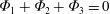 ${\it\Phi}_{1}+{\it\Phi}_{2}+{\it\Phi}_{3}=0$
, where
${\it\Phi}_{1}+{\it\Phi}_{2}+{\it\Phi}_{3}=0$
, where
 ${\it\Phi}_{1}$
is the flux gained from the previous segment,
${\it\Phi}_{1}$
is the flux gained from the previous segment,
 ${\it\Phi}_{2}$
is the flux lost to the next segment and
${\it\Phi}_{2}$
is the flux lost to the next segment and
 ${\it\Phi}_{3}$
is the flux lost by detrainment directly from the street segment into the boundary layer aloft. Denoting the concentration along the street as a continuous function
${\it\Phi}_{3}$
is the flux lost by detrainment directly from the street segment into the boundary layer aloft. Denoting the concentration along the street as a continuous function
 $C(s)$
of the distance
$C(s)$
of the distance
 $s$
along the street and the external concentration just above the street as a corresponding function
$s$
along the street and the external concentration just above the street as a corresponding function
 $D(s)$
, this flux balance can be written
$D(s)$
, this flux balance can be written
 $$\begin{eqnarray}\text{d}(whU_{S}C(s))=-E_{S}w\{C(s)-D(s)\}\,\text{d}s-W_{S}wC(s)\,\text{d}s,\end{eqnarray}$$
where
 $w$
and
$w$
and
 $h$
are the width and height of the street,
$h$
are the width and height of the street,
 $U_{S}$
is the advection velocity along the street,
$U_{S}$
is the advection velocity along the street,
 $E_{S}$
is the turbulent exchange velocity and
$E_{S}$
is the turbulent exchange velocity and
 $W_{S}$
is the advection velocity out of the street top. When the street is uniform in width and height, this gives
$W_{S}$
is the advection velocity out of the street top. When the street is uniform in width and height, this gives
 $$\begin{eqnarray}\frac{\text{d}C(s)}{\text{d}s}=-\frac{\{C(s)-{\it\lambda}D(s)\}}{l_{d}},\end{eqnarray}$$
where
 ${\it\lambda}=E_{S}/(E_{S}+W_{S})$
and
${\it\lambda}=E_{S}/(E_{S}+W_{S})$
and
 $l_{d}=hU_{S}/(E_{S}+W_{S})$
, so that exchange of scalar between the street and the air above occurs over the detrainment length scale
$l_{d}=hU_{S}/(E_{S}+W_{S})$
, so that exchange of scalar between the street and the air above occurs over the detrainment length scale
 $l_{d}$
. A long street can then be defined as one whose length
$l_{d}$
. A long street can then be defined as one whose length
 $l_{S}\gg l_{d}$
. The street then needs to be broken into
$l_{S}\gg l_{d}$
. The street then needs to be broken into
 $n_{S}$
street boxes each with length less than
$n_{S}$
street boxes each with length less than
 $l_{d}$
in order for the concentration within each street box to be regarded as constant. For the DNS case in this paper,
$l_{d}$
in order for the concentration within each street box to be regarded as constant. For the DNS case in this paper,
 $l_{d}\approx 4h$
while
$l_{d}\approx 4h$
while
 $l_{S}=h$
, so that the streets can be regarded as short. We note that, when the concentration in the air aloft
$l_{S}=h$
, so that the streets can be regarded as short. We note that, when the concentration in the air aloft
 $D(s)\ll C(s)$
, the concentration decays exponentially along the street:
$D(s)\ll C(s)$
, the concentration decays exponentially along the street:
 $C(s)=C(0)\,\text{e}^{-s/l_{d}}$
.
$C(s)=C(0)\,\text{e}^{-s/l_{d}}$
.
Flux balance in a long street. The street width is
 $w$
and
$w$
and
 $U_{S}$
is a characteristic advection velocity along the street. Dividing up the street into segments of length
$U_{S}$
is a characteristic advection velocity along the street. Dividing up the street into segments of length
 $\text{d}s$
, the middle street segment receives scalar flux
$\text{d}s$
, the middle street segment receives scalar flux
 ${\it\Phi}_{1}$
from the previous segment, loses
${\it\Phi}_{1}$
from the previous segment, loses
 ${\it\Phi}_{2}$
to the next segment and loses
${\it\Phi}_{2}$
to the next segment and loses
 ${\it\Phi}_{3}$
by detrainment into the above air.
${\it\Phi}_{3}$
by detrainment into the above air.

Appendix B. Derivation of solution without re-entrainment
This appendix gives the derivation of the network model solution (5.2) for a regular array in the absence of re-entrainment.
Close to the source, where the
 $D$
terms in (4.11) are small, the equation can be approximated as
$D$
terms in (4.11) are small, the equation can be approximated as
 $$\begin{eqnarray}C_{i,j}=a\,C_{i-1,j}+b\,C_{i,j-1}+S_{i,j},\end{eqnarray}$$
for
 $i,j\geqslant 0$
and where, for mathematical simplicity, we have introduced coefficients
$i,j\geqslant 0$
and where, for mathematical simplicity, we have introduced coefficients
 $a$
and
$a$
and
 $b$
related to
$b$
related to
 ${\it\alpha}$
and
${\it\alpha}$
and
 $p$
by
$p$
by
 ${\it\alpha}=a+b$
and
${\it\alpha}=a+b$
and
 $p=a/(a+b)$
.
$p=a/(a+b)$
.
We first solve equation (B 1) for a single source at node
 $(0,0)$
, i.e. the normalised source emission rate
$(0,0)$
, i.e. the normalised source emission rate
 $S_{i,j}$
is zero except for
$S_{i,j}$
is zero except for
 $i=j=0$
. This is a linear inhomogeneous two-dimensional recurrence relation (it is homogeneous for all but
$i=j=0$
. This is a linear inhomogeneous two-dimensional recurrence relation (it is homogeneous for all but
 $i=j=0$
). The objective is to obtain a closed-form solution of (B 1) in terms of the source
$i=j=0$
). The objective is to obtain a closed-form solution of (B 1) in terms of the source
 $S_{0,0}$
.
$S_{0,0}$
.
To achieve this, we use the method of generating functions (Wilf Reference Wilf1994). The solution method consists of first introducing a generating function of the form
 $$\begin{eqnarray}B_{i}(x)=\mathop{\sum }_{j\geqslant 0}C_{i,j}\,x^{j},\end{eqnarray}$$
i.e. the concentrations
 $C_{i,j}$
are given by the coefficients in the power series expansion of the generating function
$C_{i,j}$
are given by the coefficients in the power series expansion of the generating function
 $B_{i}(x)$
. The rest of the method consists of finding an explicit expression for the expansion (B 2), and hence for the coefficients
$B_{i}(x)$
. The rest of the method consists of finding an explicit expression for the expansion (B 2), and hence for the coefficients
 $C_{i,j}$
.
$C_{i,j}$
.
Multiplying both sides of (B 1) by
 $x^{j}$
and performing the sum over
$x^{j}$
and performing the sum over
 $\sum _{j\geqslant 1}$
, one can show that
$\sum _{j\geqslant 1}$
, one can show that
 $$\begin{eqnarray}B_{i}(x)=\frac{1}{1-bx}\,[a\,B_{i-1}(x)+b\,C_{i,-1}],\end{eqnarray}$$
for
 $i\geqslant 1$
, whilst from (B 2),
$i\geqslant 1$
, whilst from (B 2),
 $B_{0}(x)=\sum _{j\geqslant 0}C_{0,j}\,x^{j}$
.
$B_{0}(x)=\sum _{j\geqslant 0}C_{0,j}\,x^{j}$
.
To proceed, one needs to find, or specify, the values of
 $C_{i,-1}$
as well as the concentrations on the array edge
$C_{i,-1}$
as well as the concentrations on the array edge
 $C_{0,j}$
for all
$C_{0,j}$
for all
 $j\geqslant 0$
.
$j\geqslant 0$
.
A reasonable choice is to set
 $C_{i,-1}=0$
for all
$C_{i,-1}=0$
for all
 $i$
and
$i$
and
 $C_{-1,j}=0$
for all
$C_{-1,j}=0$
for all
 $j$
. This corresponds to the assumption that there is negligible backward dispersion, and is consistent with the approach of considering only horizontal fluxes along the mean wind components that led to (B 1). We note that other choices (not explored here) would give different solutions.
$j$
. This corresponds to the assumption that there is negligible backward dispersion, and is consistent with the approach of considering only horizontal fluxes along the mean wind components that led to (B 1). We note that other choices (not explored here) would give different solutions.
The first condition
 $C_{i,-1}=0$
gives
$C_{i,-1}=0$
gives
 $$\begin{eqnarray}B_{i}(x)=\frac{a}{1-bx}\,B_{i-1}(x),\end{eqnarray}$$
for
 $i\geqslant 1$
, from which one can immediately infer
$i\geqslant 1$
, from which one can immediately infer
 $$\begin{eqnarray}B_{i}(x)=a^{i}(1-bx)^{-i}\,B_{0}(x),\end{eqnarray}$$
for
 $i\geqslant 1$
. The conditions
$i\geqslant 1$
. The conditions
 $C_{i,-1}=0$
and
$C_{i,-1}=0$
and
 $C_{-1,j}=0$
also give, via (B 1),
$C_{-1,j}=0$
also give, via (B 1),
 $C_{i,0}=a\,C_{i-1,0}$
and
$C_{i,0}=a\,C_{i-1,0}$
and
 $C_{0,j}=b\,C_{0,j-1}$
, which imply that
$C_{0,j}=b\,C_{0,j-1}$
, which imply that
 $$\begin{eqnarray}\displaystyle & C_{i,0}=a^{i}\,C_{0,0}, & \displaystyle\end{eqnarray}$$
 $$\begin{eqnarray}\displaystyle & C_{0,j}=b^{j}\,C_{0,0}, & \displaystyle\end{eqnarray}$$
 $i,j\geqslant 0$
. These equations show that, for a single source, the concentration along the two street directions should decrease as a geometric progression with the number of intersections from the source location. This simple consequence of the model can be readily verified with available data.
$i,j\geqslant 0$
. These equations show that, for a single source, the concentration along the two street directions should decrease as a geometric progression with the number of intersections from the source location. This simple consequence of the model can be readily verified with available data.
Using this solution in the expression for
 $B_{0}(x)$
then gives
$B_{0}(x)$
then gives
 $$\begin{eqnarray}B_{0}(x)=\mathop{\sum }_{j\geqslant 0}C_{0,0}\,b^{j}\,x^{j}=\frac{C_{0,0}}{1-bx}.\end{eqnarray}$$
This gives
 $$\begin{eqnarray}\displaystyle B_{i}(x) & = & \displaystyle a^{i}(1-bx)^{-i-1}\,C_{0,0}\end{eqnarray}$$
 $$\begin{eqnarray}\displaystyle & = & \displaystyle \mathop{\sum }_{j\geqslant 0}\frac{(i+j)!}{i!j!}a^{i}\,b^{j}\,C_{0,0}\,x^{j}.\end{eqnarray}$$
 $$\begin{eqnarray}C_{i,j}=\binom{i+j}{j}\,a^{i}\,b^{j}\,C_{0,0}.\end{eqnarray}$$
This relates the concentration in the
 $(i,j)$
th intersection to that in the
$(i,j)$
th intersection to that in the
 $(0,0)$
intersection, where the source is. But from (B 1), together with the assumptions
$(0,0)$
intersection, where the source is. But from (B 1), together with the assumptions
 $C_{i,-1}=0$
and
$C_{i,-1}=0$
and
 $C_{-1,j}=0$
, one has
$C_{-1,j}=0$
, one has
 $C_{0,0}=S_{0,0}$
. Hence,
$C_{0,0}=S_{0,0}$
. Hence,
 $$\begin{eqnarray}C_{i,j}=\binom{i+j}{j}\,a^{i}\,b^{j}\,S_{0,0}.\end{eqnarray}$$
Since
 $a={\it\alpha}p$
and
$a={\it\alpha}p$
and
 $b={\it\alpha}(1-p)$
, equation (B 12) is identical to equation (5.2). This solution is for a single source, but can be readily generalized for an arbitrary distribution of point sources. The solution is then a superposition of the single-source solution (B 12):
$b={\it\alpha}(1-p)$
, equation (B 12) is identical to equation (5.2). This solution is for a single source, but can be readily generalized for an arbitrary distribution of point sources. The solution is then a superposition of the single-source solution (B 12):
 $$\begin{eqnarray}C_{i,j}=\mathop{\sum }_{m\geqslant 0}\mathop{\sum }_{n\geqslant 0}\,H(i-m)\,H(\,j-n)\,\binom{i+j-m-n}{j-n}\,a^{i-m}\,b^{j-n}\,S_{m,n},\end{eqnarray}$$
where
 $H(k)$
is the Heaviside step function, defined by
$H(k)$
is the Heaviside step function, defined by
 $H(k)=1$
for
$H(k)=1$
for
 $k\geqslant 0$
and
$k\geqslant 0$
and
 $H(k)=0$
for
$H(k)=0$
for
 $k<0$
.
$k<0$
.
Appendix C. A simple toy model for re-entrainment
In this appendix we formulate and solve a toy model for re-entrainment for the special case of oblique flow through the array discussed in § 6, using the methods developed in appendix B.
We assume that the material entrained into a particular intersection at node
 $(i,j)$
comes mainly from that which escapes from the previous intersection
$(i,j)$
comes mainly from that which escapes from the previous intersection
 $(i-1,j-1)$
. In other words, re-entrainment provides an alternative pathway for material to reach a node from the next nearest neighbour.
$(i-1,j-1)$
. In other words, re-entrainment provides an alternative pathway for material to reach a node from the next nearest neighbour.
With this assumption, the recurrence relation (B 1) generalises to
 $$\begin{eqnarray}C_{i,j}=a\,C_{i-1,j}+b\,C_{i,j-1}+c\,C_{i-1,j-1}+S_{i,j},\end{eqnarray}$$
where the additional constant
 $c$
is typically much smaller than 1.
$c$
is typically much smaller than 1.
We solve (C 1) for a single source located at node
 $(0,0)$
, i.e. with
$(0,0)$
, i.e. with
 $S_{i,j}=S_{0,0}\,{\it\delta}_{i,0}\,{\it\delta}_{j,0}$
. Using the same generating function (B 2), multiplying both sides of (C 1) by
$S_{i,j}=S_{0,0}\,{\it\delta}_{i,0}\,{\it\delta}_{j,0}$
. Using the same generating function (B 2), multiplying both sides of (C 1) by
 $x^{j}$
and performing the sum over
$x^{j}$
and performing the sum over
 $\sum _{j\geqslant 1}$
, one can show that
$\sum _{j\geqslant 1}$
, one can show that
 $$\begin{eqnarray}B_{i}(x)=\frac{(a+cx)B_{i-1}(x)+C_{i,0}-a\,C_{i-1,0}}{(1-bx)}.\end{eqnarray}$$
Using (C 1), one finds
 $$\begin{eqnarray}C_{i,0}-a\,C_{i-1,0}=b\,C_{i,-1}+c\,C_{i-1,-1},\end{eqnarray}$$
so that, assuming as before that
 $C_{i,-1}=0$
for all
$C_{i,-1}=0$
for all
 $i$
gives
$i$
gives
 $C_{i,0}-a\,C_{i-1,0}=0$
, and hence
$C_{i,0}-a\,C_{i-1,0}=0$
, and hence
 $$\begin{eqnarray}B_{i}(x)=(a+cx)(1-bx)^{-1}B_{i-1}(x)\quad \text{for}~i\geqslant 1,\end{eqnarray}$$
which has solution
 $$\begin{eqnarray}B_{i}(x)=(a+cx)^{i}(1-bx)^{-i}B_{0}(x).\end{eqnarray}$$
With the same assumptions
 $C_{i,-1}=C_{-1,j}=0$
, equations (B 6)–(B 8) remain true, so that now
$C_{i,-1}=C_{-1,j}=0$
, equations (B 6)–(B 8) remain true, so that now
 $$\begin{eqnarray}B_{i}(x)=(a+cx)^{i}(1-bx)^{-i-1}C_{0,0}.\end{eqnarray}$$
This is similar to (B 10), except for an additional term
 $cx$
in the first factor, which therefore now has a power series expansion too. Using the binomial theorem gives
$cx$
in the first factor, which therefore now has a power series expansion too. Using the binomial theorem gives
 $$\begin{eqnarray}\displaystyle B_{i}(x) & = & \displaystyle C_{0,0}\,\mathop{\sum }_{m\geqslant 0}^{i}\,\binom{i}{m}\,a^{i-m}\,c^{m}\,x^{m}\,\mathop{\sum }_{n\geqslant 0}\,\binom{i+n}{i}\,b^{n}\,x^{n}\end{eqnarray}$$
 $$\begin{eqnarray}\displaystyle & = & \displaystyle \mathop{\sum }_{m\geqslant 0}^{i}\,\mathop{\sum }_{n\geqslant 0}\,\binom{i}{m}\,\binom{i+n}{i}\,a^{i-m}\,b^{n}\,c^{m}\,C_{0,0}\,x^{m+n}\end{eqnarray}$$
 $$\begin{eqnarray}\displaystyle & = & \displaystyle \mathop{\sum }_{m\geqslant 0}^{i}\,\mathop{\sum }_{j\geqslant m}\,\binom{i}{m}\,\binom{i+j-m}{i}\,a^{i-m}\,b^{j-m}\,c^{m}\,C_{0,0}\,x^{j},\end{eqnarray}$$
 $j=m+n$
and replacing
$j=m+n$
and replacing
 $n$
by
$n$
by
 $j-m$
.
$j-m$
.
The sum
 $\sum _{j\geqslant m}\,(\dots )$
can be replaced by
$\sum _{j\geqslant m}\,(\dots )$
can be replaced by
 $\sum _{j\geqslant 0}\,(\dots )\,H(j-m)$
, where
$\sum _{j\geqslant 0}\,(\dots )\,H(j-m)$
, where
 $H$
is the Heaviside step function, so that
$H$
is the Heaviside step function, so that
 $$\begin{eqnarray}B_{i}(x)=\mathop{\sum }_{j\geqslant 0}\,\mathop{\sum }_{m\geqslant 0}^{i}\,H(j-m)\,\binom{i}{m}\,\binom{i+j-m}{i}\,a^{i-m}\,b^{j-m}\,c^{m}\,C_{0,0}\,x^{j},\end{eqnarray}$$
and comparing with (B 2) and replacing
 $C_{0,0}=S_{0,0}$
finally gives the solution with re-entrainment as
$C_{0,0}=S_{0,0}$
finally gives the solution with re-entrainment as
 $$\begin{eqnarray}C_{i,j}=\mathop{\sum }_{m\geqslant 0}^{i}\,H(j-m)\,\binom{i}{m}\,\binom{i+j-m}{i}\,a^{i-m}\,b^{j-m}\,c^{m}\,S_{0,0}.\end{eqnarray}$$
Note that the
 $m=0$
term in (C 11) is identical with (B 12) and that the remaining terms vanish if
$m=0$
term in (C 11) is identical with (B 12) and that the remaining terms vanish if
 $c=0$
, so that (C 11) reduces to the solution without re-entrainment (B 12) for
$c=0$
, so that (C 11) reduces to the solution without re-entrainment (B 12) for
 $c=0$
. The solution (C 11) exists as a sum over
$c=0$
. The solution (C 11) exists as a sum over
 $m$
because each intersection gains material by re-entrainment from the previous intersection, and then passes on some of that material to the next one; hence, the effect is cumulative. In effect, this gives a series in powers of
$m$
because each intersection gains material by re-entrainment from the previous intersection, and then passes on some of that material to the next one; hence, the effect is cumulative. In effect, this gives a series in powers of
 $c/(ab)$
, which is therefore a relevant parameter for characterising the re-entrainment.
$c/(ab)$
, which is therefore a relevant parameter for characterising the re-entrainment.
For multiple sources, equation (C 11) generalises to
 $$\begin{eqnarray}C_{i,j}=\mathop{\sum }_{m=0}^{i}\mathop{\sum }_{n=0}^{j}\mathop{\sum }_{s=0}^{i-m}\,H(\,j-n-s)\,\binom{i-m}{s}\,\binom{i+j-m-n-s}{i-m}\,a^{i-m-s}\,b^{j-n-s}\,c^{s}\,S_{m,n}.\end{eqnarray}$$


