


1. Introduction
Within the last two centuries, surgical interventions progressed more and more toward minimally invasive surgery (MIS) [Reference Simaan, Yasin and Wang1]. MIS is less invasive than open surgery, and therefore results in less collateral damage to healthy tissue and faster patient recovery [Reference Wei, Qi, Chen, Zheng, Huang, Hu and Wei2, Reference de Goede, Klitsie, Hagen, van Kempen, Spronk, Metselaar, Lange and Kazemier3]. In surgical procedures that involve the cutting of bone, such as joint arthroplasty, cranial and maxillofacial surgery, or spine surgery, replacing open surgeries by MIS is challenging. Processing of bone typically requires mechanical tools, such as bone saws and drills, and therefore high contact forces arise between these medical instruments and the tissue. The need to apply high forces to the tissue makes the development of dexterous, small-diameter instruments with high positioning accuracy challenging.
For procedures without large-area bone machining, for example, drilling of individual holes, robotic devices for high-precision minimally invasive bone processing have been realized. For example, robotic systems for pedicle screw placement in spine surgery, including Mazor X Stealth Edition (Mazor Robotics, Caesareas, Israel) [Reference OConnor, OHehir, Khan, Mao, Levy, Mullin and Pollina4] (previous versions include Mazor X [Reference Khan, Meyers, Siasios and Pollina5], Renaissance, SpineAssist [Reference Lieberman, Togawa, Kayanja, Reinhardt, Friedlander, Knoller and Benzel6–Reference Devito, Kaplan, Dietl, Pfeiffer, Horne, Silberstein, Hardenbrook, Kiriyanthan, Barzilay, Bruskin, Sackerer, Alexandrovsky, Stüer, Burger, Maeurer, Gordon, Schoenmayr, Friedlander, Knoller, Schmieder, Pechlivanis, Kim, Meyer and Shoham8], and the MARS [Reference Shoham, Burman, Zehavi, Joskowicz, Batkilin and Kunicher9]), ExcelsiusGPS (Globus Medical, Audubon, PA, USA) [Reference Jiang, Ahmed, Zygourakis, Kalb, Zhu, Godzik, Molina, Blitz, Bydon, Crawford and Theodore10–Reference Ahmed, Zygourakis, Kalb, Zhu, Molina, Jiang, Blitz, Bydon, Crawford and Theodore12], and ROSA (Zimmer Biomet, Warsaw, IN, USA) [Reference Chenin, Peltier and Lefranc13, Reference Lefranc and Peltier14], or robotic systems for instrument guidance along a drilling trajectory for the accurate placement of cochlear implants [Reference Kratchman, Blachon, Withrow, Balachandran, Labadie and Webster15–Reference Caversaccio, Gavaghan, Wimmer, Williamson, Anso, Mantokoudis, Gerber, Rathgeb, Feldmann, Wagner, Scheidegger, Kompis, Weisstanner, Zoka-Assadi, Roesler, Anschuetz, Huth and Weber18].
However, in other procedures, for example, in knee arthroplasty, large-area bone machining is required to generate bone cuts of several centimeters length or surface milling of several square centimeters [Reference Wolf, Jaramaz, Lisien and DiGioia19, Reference Eugster, Zoller, Krenn, Blache, Friederich, Müller-Gerbl, Cattin and Rauter20]. Effort has been invested in making knee arthroplasty procedures less invasive. To this end, miniature bone-mounted robots for knee arthroplasty have been developed [Reference Netravali, Shen, Park and Bargar21], such as the Mini Bone-Attached Robotic System [Reference Wolf, Jaramaz, Lisien and DiGioia22] and the Hybrid Bone-Attached Robot [Reference Song, Mor and Jaramaz23]. However, these devices are based on rigid instruments that require a large manipulation space above the bone.
In contrast to abdominal or endoluminal minimally invasive surgery, where a relatively large cavity is available for surgical tool manipulation, bones are often densely surrounded by tissue such as joint capsules, tendons, and muscles. Thus, only a relatively small and narrow space is available above the bone surfaces for manipulating a tool in a minimally invasive manner. For procedures requiring large-area bone machining to be performed in a minimally invasive manner, a small-diameter instrument capable of moving along the bone surface while maintaining a minimal manipulation space perpendicular to the bone surface would be required. We see the main challenges in realizing such a dexterous mechanical device for accurate, minimally invasive, large-area machining of bone in the (i) presence of bone-cutting forces, (ii) cutting accuracy required in a large workspace, and (iii) realization of a small-diameter device that allows manipulation in the narrow space available above bone.
To address challenge (i) regarding cutting forces, we aim to enable thin and accurate bone cuts in a minimally invasive manner by using a laser. Mechanical bone cutting using mills, drills, or cutters can lead to high cutting forces (e.g., up to 21 N [Reference Federspil, Plinkert and Plinkert24]). The so-called laser osteotomy offers a low contact force alternative to cutting bone with conventional mechanical tools [Reference Burgner25] and enables faster bone healing, higher cutting accuracy, and increased freedom in the cutting geometry [Reference Augello, Deibel, Nuss, Cattin and Jürgens26]. To enable accurate and, in particular, deep bone cuts, the laser must be moved several times in submillimeter steps along the cutting path, and therefore requires robotic assistance [Reference Burgner, Müller, Raczkowsky and Wrn27]. Robotic laser osteotomes are already available for an open surgical approach [Reference Deibel, Schneider, Augello, Bruno, Juergens and Cattin28, Reference Cattin, Griessen, Schneider and Bruno29]. However, to our knowledge, no minimally invasive tool for laser osteotomy has been realized so far.
We develop our device targeted for unicondylar knee arthroplasty (UKA), a treatment option for osteoarthritis. Osteoarthritis has a high socioeconomic impact, causes severe long-term pain, and is globally the most common cause for physical disability [Reference Scientific Group30, Reference Bertrand31]. UKA is a less invasive option for a knee replacement compared to total knee arthroplasty (TKA) and can be chosen when only one knee compartment is affected by osteoarthritis. The advantages of UKA compared to TKA include reduced blood loss [Reference Yang, Wang, Yeo and Lo32], lower infection rate [Reference Bengtson and Knutson33], less postoperative pain [Reference Noticewala, Geller, Lee and Macaulay34], faster recovery [Reference Yang, Wang, Yeo and Lo32], better preservation of range-of-motion [Reference Laurencin, Zelicof, Scott and Ewald35], better function [Reference Newman, Pydisetty and Ackroyd36], and lower cost [Reference Robertsson, Borgquist, Knutson, Lewold and Lidgren37]. However, UKA is less resistant to component malalignment [Reference Plate, Mofidi, Mannava, Lorentzen, Smith, Seyler, McTighe and Jinnah38] compared to TKA. Correct alignment of the implant components is crucial for long-term survival of a unicondylar knee implant [Reference Hamilton, Collier, Tarabee, McAuley, Engh and Engh39], since poor implant positioning may lead to early implant wear [Reference Hernigou and Deschamps40], poor functional results [Reference Weinstein, Andriacchi and Galante41], and a higher revision rate [Reference Barbadoro, Ensini, Leardini, d’Amato, Feliciangeli, Timoncini, Amadei, Belvedere and Giannini42]. Our device could help to improve UKA in different ways. For example, accuracy of placement and fixation of implants could be improved by the possibility of functional cutting geometries, such as a dovetail guide. Also, the intervention would become less invasive due to the smaller opening required for inserting the dexterous, small-diameter device and the reduced collateral mechanical and thermal tissue damage of laser bone cuts compared to bone saw cuts [Reference Stbinger, Nuss, Pongratz, Price, Sader, Zeilhofer and von Rechenberg43].
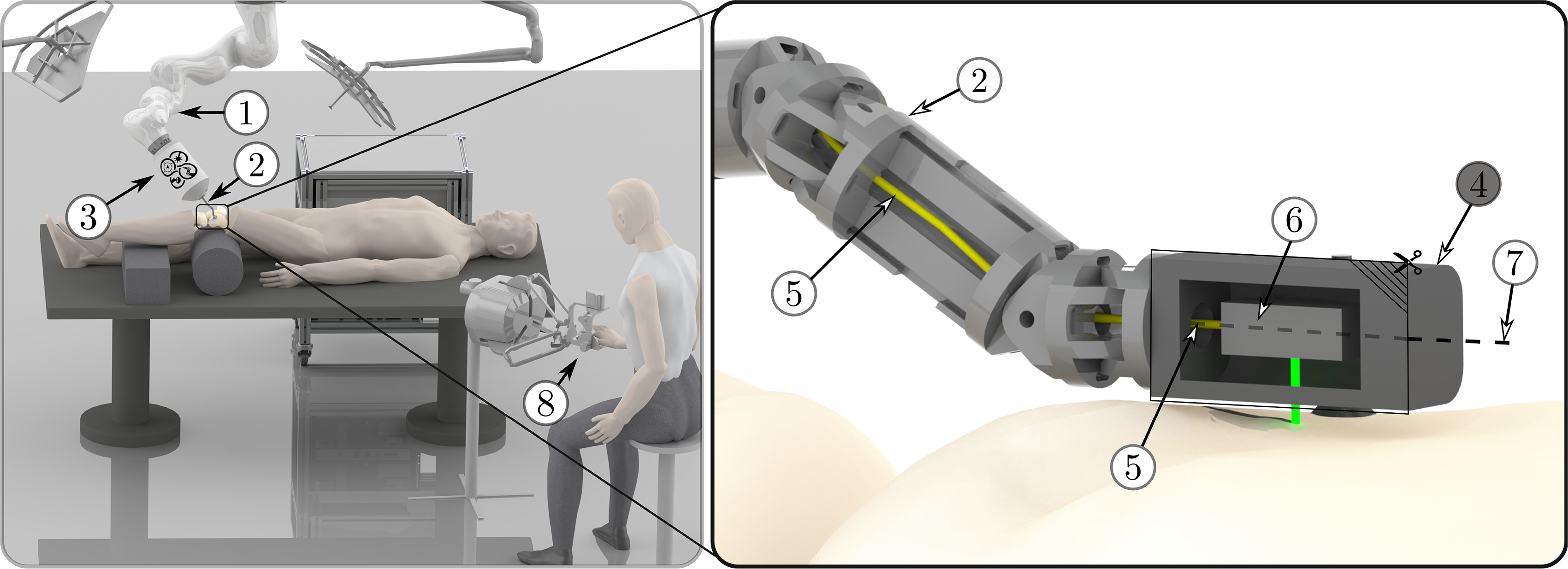
To address challenge (ii) on high accuracy in a large workspace, we are developing a system for minimally invasive laser osteotomy based on the macro–micro approach (Fig. 1). The macrosystem has a large workspace but poor accuracy, while the microsystem, which is the focus of this article, has a smaller workspace but higher accuracy.
Illustration of the overall setup: A serial robot (1) guides a robotic endoscope (2) for minimally invasive laser osteotomy, including its actuation unit (3). The laser is guided through the endoscope to the endoscope tip segment (4) by an optical fiber (5). One end of the fiber is connected to the laser source, located outside the patient and the other end is connected to the laser optics (6) inside the endoscope tip. The laser optics redirect the laser beam, which then exits the endoscope tip perpendicular to its longitudinal axis (7) and is directed toward the bone surface. The endoscope tip segment is a standalone miniature robot, which can guide the laser optics to enable accurate bone ablation. The system can be controlled by a surgeon using telemanipulation (8).
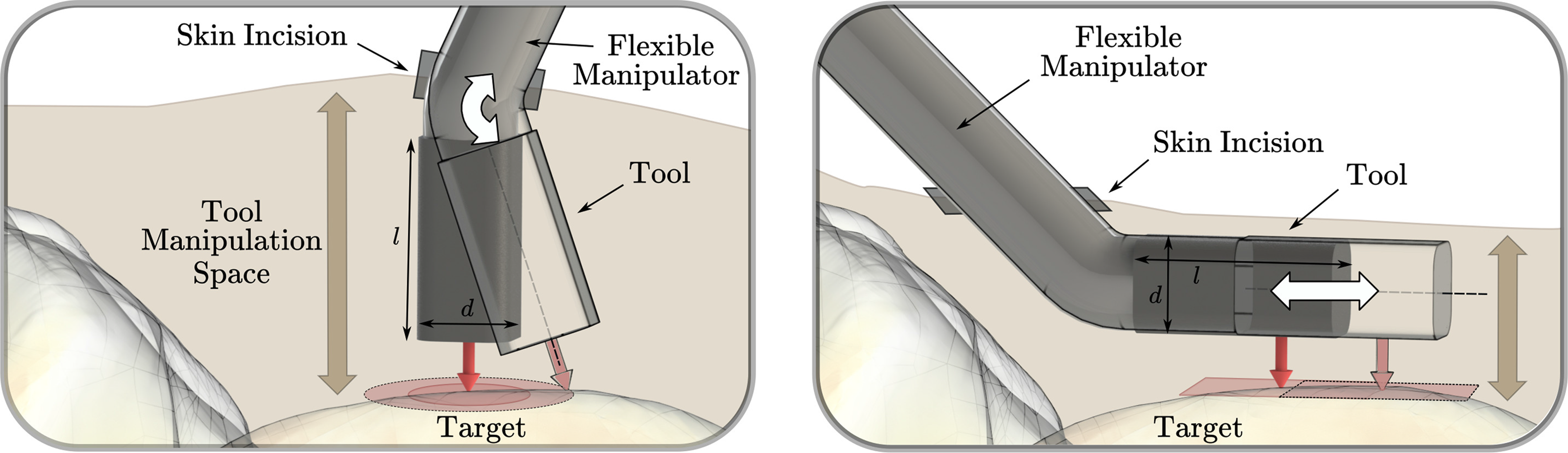
Two possible orientations of the longitudinal axis of the tool are shown: perpendicular to the target surface (left) and parallel to the target surface (right). For the left setup, assuming one skin incision, the workspace mainly depends on the bending capability of the distal tool element and the distance of the bending axis to the target surface. The required manipulation space mainly depends on the length l of the last rigid structure of the tool. For the setup on the right side, the workspace that can be reached depends mainly on the ability of the tool to translate parallel to the target surface. The required manipulation space primarily depends on the tool diameter d. Therefore, the device setup on the right side is better suited for minimally invasive large-area tool manipulation in narrow regions above bone.
The macrosystem consists of a serial robot that guides a robotic endoscope, whereas the microsystem is a miniature robot with integrated laser optics mounted at the endoscope’s tip. Once the macrosystem positioned the miniature robot on the bone, the miniature robot attaches to the bone and accurately guides the laser in a minimally invasive approach. The miniature robot has to allow at least two degrees of freedom (DoFs) to position the laser parallel to the bone surface for cutting. Based on the currently envisioned diameter of the laser focal point of 0.5 mm [Reference Bernal, Schmidt, Vulin, Widmer, Snedeker, Cattin, Zam and Rauter44], we aim to achieve a positioning accuracy below 0.25 mm for the miniature robot to enable the realization of continuous laser cuts based on pointwise ablation.
Concerning challenge (iii) on small dimensions and a narrow manipulation space, we aim at a device height below 8 mm for our prototype, according to our first target application (UKA). This height limit is based on the manipulation volume that we expected to be available for a minimally invasive intervention inside the knee joint based on cadaver experiments previously performed [Reference Eugster, Zoller, Krenn, Blache, Friederich, Müller-Gerbl, Cattin and Rauter20], as well as on the dimensions of the tools in basic surgical instrument sets used for knee arthroscopy such as shavers, arthroscope shafts, and barrel burrs [45].
Dexterous robotic devices for minimally invasive surgery were mainly developed for abdominal or endoluminal surgical applications and were often constructed such that the device consists of a distal structure with rotational degrees of freedom for bending, which orients the longitudinal axis of the tool toward the area of interest. While the diameter of these devices was minimized to reduce the skin incision needed for insertion, the last segment’s length was not the main focus of miniaturization. This approach has drawbacks for application in confined and narrow spaces. In contrast, orienting the tool’s longitudinal axis parallel to the target surface allows minimizing the required manipulation space above the surface without limiting the workspace of the tool (Fig. 2).
Examples of existing devices where the tool’s longitudinal axis was oriented parallel to the target surface included: a parallel wire robot for injections into the myocardium [Reference Costanza, Breault, Wood, Passineau, Moraca and Riviere46], and a miniaturized robotic probe for endomicroscopy [Reference Dwyer, Giataganas, Pratt, Hughes and Yang47]. However, the parallel wire robot’s positioning accuracy was in the range of millimeters, and no positioning accuracy was stated for the miniaturized robotic probe. To our knowledge, dexterous endoscopic instruments for minimally invasive insertion and manipulation of surgical tools with a reported tool or tip accuracy with respect to the patient (or test bench) below 0.25 mm include the magnetic laser scanner module for endoscopic microsurgeries [Reference Acemoglu, Pucci and Mattos48] and the micropositioner for confocal endomicroscopy [Reference Rosa, Herman, Szewczyk, Gayet and Morel49]. However, both these devices require a large manipulation space above the target tissue due to their orientation relative to the target tissue and dimensions. These and other examples of existing miniature robotic tools for minimally invasive surgery that do not provide accuracy specifications or reported a tool tip positioning accuracy above 0.25 mm are listed in Table A.1 in Appendix A.
We do not know of any robotic device with a height below 8 mm that allows dexterous manipulation inside confined and narrow spaces at an accuracy relative to the target tissue (or test bench) below 0.25 mm. Recently, we presented the topology of a bone-attached parallel robot that has the potential to satisfy our requirements for accurate, minimally invasive, large-area laser osteotomy [Reference Eugster, Weber, Cattin, Zam, Kosa and Rauter50]. Based on the first upscaled prototype, we demonstrated the proof of concept of the parallel structure [Reference Eugster, Cattin, Zam and Rauter51]. However, in this upscaled setup, many key challenges were not addressed, because the setup was built without size constraints resulting in a device with overall dimensions of 115 mm × 35 mm × 40 mm.
The work presented in this paper focuses on the miniaturization and first evaluation of the parallel robot mechanics designed to allow future minimally invasive positioning of a laser with minimal manipulation space requirements above the target surface. For the first time, we present the miniaturized version of the parallel robot with a height below 8 mm and a novel actuation and position sensing. We evaluate the robot’s positioning accuracy on the test bench. Further important system components such as integrating a high-power laser, the design of the parallel robot’s legs and attachment to bone, or the large-scale guidance of the miniature parallel robot with a macrosystem are research topics per se and are referenced but not detailed in this work. Also, work on the challenges in the field of laser physics are not the focus of this paper and are presented elsewhere (e.g., high-power laser coupling efficiency into optical fibers [Reference Bernal, Canbaz, Friederich, Cattin and Zam52], or real-time tissue differentiation [Reference Abbasi, Bernal, Hamidi, Droneau, Canbaz, Guzman, Jacques, Cattin and Zam53]).
2. The Miniature Parallel Robot
2.1. Concept
The parallel robot presented herein consists of four actuated chains that connect the moving platform to the base of the robot, that is, the bone. The connection of the robot to the bone is realized by directly attaching the robot’s legs to the bone. The legs’ position relative to the bone could be fixed based on a noninvasive concept, for example, suction cups [Reference Eugster, Oliveira Barros, Cattin and Rauter54] or balloon catheters. Details on the attachment of the legs to the bone are a research topic per se, and will therefore not be further discussed in this article. The moving platform of the parallel robot is the endoscope’s tip segment, which houses the laser optics. Each actuated chain is of the RRP type, that is, two passive rotary joints followed by an actuated prismatic joint. In total, there are four prismatic actuators; thus, this robot structure is abbreviated as 4-RRP (Fig. 3, visualization of the robot topology and motion available as supplementary video material). This structure allows movement of the laser optics (see (5) in Fig. 3) in two translational DoFs $\left\lbrace \vec{e}^B_x, \vec{e}^B_y \right\rbrace$
, and one rotational DoF
$\left\lbrace \vec{e}^B_x, \vec{e}^B_y \right\rbrace$
, and one rotational DoF $\varphi_e$
(see (3) in Fig. 3). The origin B of the robot’s base frame is defined to be located at the center point of the connecting line between the two attachment points of the robot on the bone. The x-axis of the frame is directed toward the right attachment point
$\varphi_e$
(see (3) in Fig. 3). The origin B of the robot’s base frame is defined to be located at the center point of the connecting line between the two attachment points of the robot on the bone. The x-axis of the frame is directed toward the right attachment point $\vec{p}_r$
, and the z-axis is defined to be parallel to the robot’s legs (
$\vec{p}_r$
, and the z-axis is defined to be parallel to the robot’s legs ( $\vec{n}_1$
and
$\vec{n}_1$
and $\vec{n}_2$
, Fig. 3).
$\vec{n}_2$
, Fig. 3).
The parallel robot has two legs (1) that are firmly attached to the bone at $\left\lbrace \vec{p}_l,\vec{p}_r \right\rbrace$
and directed along
$\left\lbrace \vec{p}_l,\vec{p}_r \right\rbrace$
and directed along $\left\lbrace \vec{n}_1,\vec{n}_2 \right\rbrace$
. The right leg (attached at
$\left\lbrace \vec{n}_1,\vec{n}_2 \right\rbrace$
. The right leg (attached at $\vec{p}_r$
) consists of two revolute joints
$\vec{p}_r$
) consists of two revolute joints $\left\lbrace R_1,R_3 \right\rbrace$
with rotation axis
$\left\lbrace R_1,R_3 \right\rbrace$
with rotation axis $\vec{n}_1$
. Revolute joint
$\vec{n}_1$
. Revolute joint $R_1$
is connected to a link
$R_1$
is connected to a link $L_1$
(2) with a fixed length of
$L_1$
(2) with a fixed length of $d_a$
. The other end of
$d_a$
. The other end of $L_1$
is connected to a further revolute joint
$L_1$
is connected to a further revolute joint $R_2$
, which can slide along the supporting link
$R_2$
, which can slide along the supporting link $A_1B_1$
. The motion of
$A_1B_1$
. The motion of $R_2$
along
$R_2$
along $A_1B_1$
is controlled by prismatic actuator
$A_1B_1$
is controlled by prismatic actuator $P_1$
, which adjusts the distance between
$P_1$
, which adjusts the distance between $A_1$
and
$A_1$
and $R_2$
. The second link
$R_2$
. The second link $L_2$
is connected to
$L_2$
is connected to $R_3$
and
$R_3$
and $R_4$
, with
$R_4$
, with $R_4$
sliding along the supporting link
$R_4$
sliding along the supporting link $A_2B_2$
. Prismatic actuator
$A_2B_2$
. Prismatic actuator $P_2$
controls the motion of
$P_2$
controls the motion of $R_4$
along
$R_4$
along $A_2B_2$
. The same arrangement is established for the other leg, which is anchored on the bone at
$A_2B_2$
. The same arrangement is established for the other leg, which is anchored on the bone at $\vec{p}_l$
with actuators
$\vec{p}_l$
with actuators $ \left\lbrace P_3,P_4 \right\rbrace$
. The positions of the prismatic joints are denoted by
$ \left\lbrace P_3,P_4 \right\rbrace$
. The positions of the prismatic joints are denoted by $\rho_i, i \in \left\lbrace 1,2,3,4 \right\rbrace$
. The two legs anchored on the bone define the base (3) of the parallel robot. The endoscope tip (4), which houses the laser optics (5), is the moving platform of the mechanism. The robot enables the movement of the laser optics, that is, the end-effector frame E, in three DoFs.
$\rho_i, i \in \left\lbrace 1,2,3,4 \right\rbrace$
. The two legs anchored on the bone define the base (3) of the parallel robot. The endoscope tip (4), which houses the laser optics (5), is the moving platform of the mechanism. The robot enables the movement of the laser optics, that is, the end-effector frame E, in three DoFs.
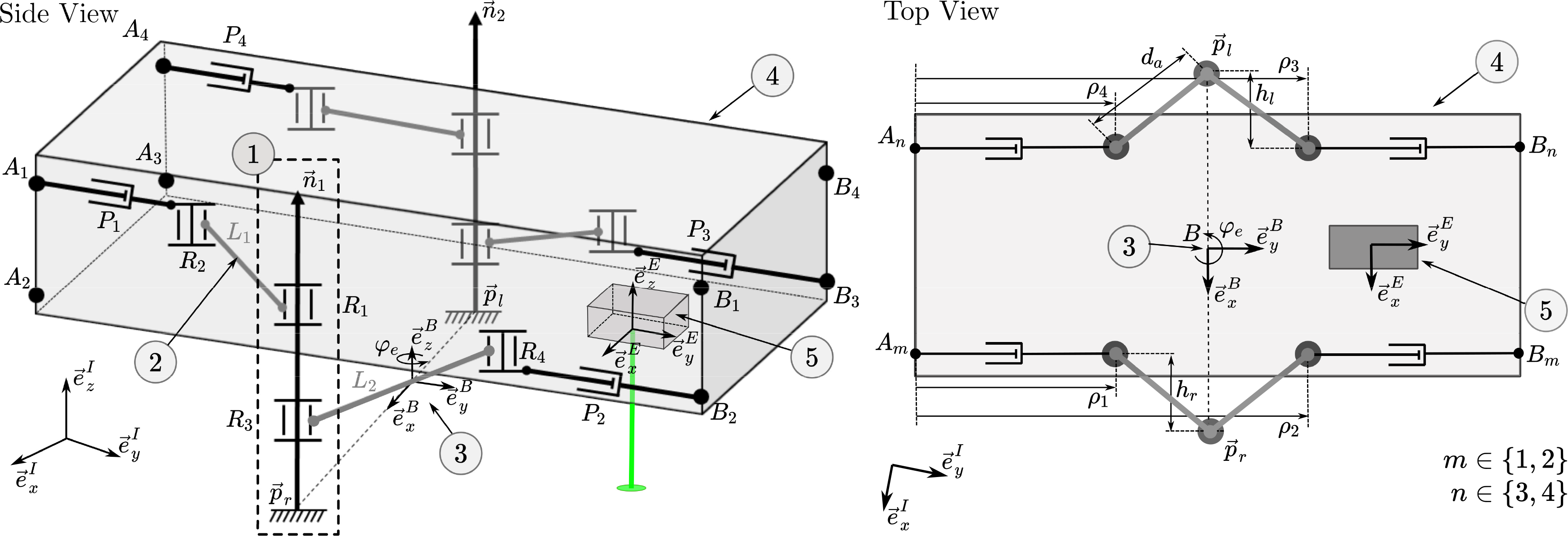
When the robot is attached to a surface, the number of controlled DoFs (three) of the end effector is smaller than the number of actuators (four); thus, the mechanism is a so-called redundant mechanism. If one of the two legs is not attached to a surface, that is, is moving in free space, the robot is not redundant. Since two actuators control the movement of each parallel robot leg, the legs can be positioned in two DoFs when they are not attached to the bone. This allows the leg and arm structure to be brought close to the robot’s main body for reducing the robot’s cross section during insertion into and retraction from the patient. Additionally, the actuation redundancy enables the robot to translate along the bone by successively repositioning its legs and therefore expanding the workspace [Reference Eugster, Oliveira Barros, Cattin and Rauter54]. A schematic visualization of this insertion, retraction, and leg repositioning is provided as Supplementary video material. Although these two features are not the focus of this work, it is essential for future work that the mechanical design of the miniature robot, the actuation concept, and the position sensing will allow the independent movement of each leg of the parallel robot.
2.2. Actuation
For minimally invasive surgery, extrinsic actuation, that is, actuators that are placed outside the patient, can be beneficial as it facilitates the design of simpler, smaller, and lighter components of the instrument parts that enter the patient. Furthermore, possible safety risks can be avoided, for example, electrical current or high-pressure hydraulics do not have to be transmitted inside the patient. However, placing the actuator outside the patient means that motion transmission elements are required, which have the drawbacks of energy losses (e.g., due to friction), backlash, and compliance. Despite existing drawbacks of extrinsic actuation, high-energy densities can be introduced in small structures from outside, while the possibility for further miniaturization remains.
The upscaled prototype of the parallel structure presented in previous work [Reference Eugster, Cattin, Zam and Rauter51] was actuated based on tendons, Bowden tubes, and pulleys. The tendons were attached to sliders that moved on linear rails. However, this prototype was built with the usage of low friction and high accuracy linear rails with built-in encoders. While tendon-driven mechanisms allow miniaturization, friction between the tendons and Bowden tubes, tendon wear, and tendon elongation under load decrease the accuracy and dynamic response of the actuator. These effects do not decrease with decreased size of the device. Furthermore, the usage of pulleys reduces the miniaturization potential since the smallest realizable pulley size depends on the limited bending radius of the tendons. Also, the used encoders for slider position feedback were not available in the required dimensions. Thus, we decided to design a novel actuation concept for the miniaturized version of the end effector.
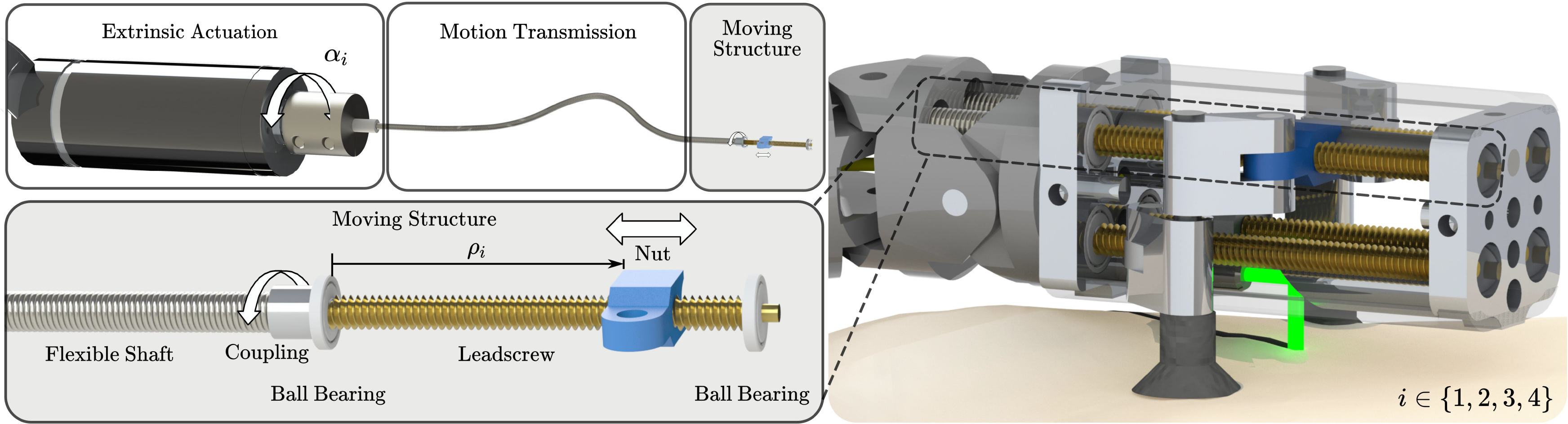
In the design for the miniaturized parallel robot, the prismatic actuators are realized as follows: Motors outside the patient are connected to flexible shafts. These flexible shafts are guided through the robotic endoscope and transfer the motor rotation to leadscrews inside the endoscope tip. These leadscrews then transfer the rotary motion of the flexible shafts into linear movements of nuts, that is, the prismatic actuators (Fig. 4). This extrinsic actuation facilitates the device miniaturization and allows using off-the-shelf electrical motors. Furthermore, by realizing the prismatic actuation as a leadscrew–nut pair, a transmission gear is directly implemented at the last moving element of the actuator. Due to the gear ratio, it is possible to measure the position of the nut by measuring the rotation of the flexible shaft using the motor encoders outside the patient body, thus eliminating the need for integration of very accurate sensors in the miniature device. To the best of our knowledge, there are only a few other devices for MIS where the benefits of the combination of flexible shafts and screws were exploited, that is, refs. [Reference Ibrahim, Ramadan, Fanni, Kobayashi, Abo-Ismail and Fujie55] and [Reference Sekiguchi, Kobayashi, Tomono, Watanabe, Toyoda, Konishi, Tomikawa, Ieiri, Tanoue, Hashizume and Fujie56].
The actuation concept for the miniature parallel robot: Flexible shafts are transmitting the rotation $\alpha_{i}$
from the externally placed electrical motors to the rotation of the leadscrews inside the end effector. These leadscrews then transfer the rotary motion of the flexible shafts into linear movements of nuts
$\alpha_{i}$
from the externally placed electrical motors to the rotation of the leadscrews inside the end effector. These leadscrews then transfer the rotary motion of the flexible shafts into linear movements of nuts $\rho_{i}$
, that is, the prismatic actuators. The miniature robot houses four such prismatic actuators.
$\rho_{i}$
, that is, the prismatic actuators. The miniature robot houses four such prismatic actuators.
2.3. Position sensing
For closed-loop control, direct absolute measurements of the positions of the actuated prismatic joints of the parallel robot and, thus, the nut positions on the leadscrews would be desirable. However, no commercial sensor is available with dimensions that would allow both direct integration into the endoscope tip and measurement of the nut positions in the submillimeter range. Therefore, for the setup presented herein, the nut positions are calculated based on the motor angles $\alpha_{i}$
, which are measured by encoders integrated into the motors located outside the patient. The motor rotation is transmitted to the leadscrews inside the endoscope tip by flexible shafts, which may introduce a rotation error
$\alpha_{i}$
, which are measured by encoders integrated into the motors located outside the patient. The motor rotation is transmitted to the leadscrews inside the endoscope tip by flexible shafts, which may introduce a rotation error $\beta_{i}$
due to torsional elasticity. The leadscrews transform the rotary motion into linear movements of the nuts. This transformation may introduce an error due to backlash
$\beta_{i}$
due to torsional elasticity. The leadscrews transform the rotary motion into linear movements of the nuts. This transformation may introduce an error due to backlash $\overline{\delta}_i$
between the leadscrew and the nut. With the leadscrew thread pitch p and under the assumption of a perfect initial calibration, the nut positions can be calculated as follows:
$\overline{\delta}_i$
between the leadscrew and the nut. With the leadscrew thread pitch p and under the assumption of a perfect initial calibration, the nut positions can be calculated as follows:
 \begin{equation}\begin{aligned}\overline{\rho}_i = \frac{p}{{360}^{\circ}} \left( \overline{\alpha}_{i}+ \overline{\beta}_{i} \right) + \overline{\delta}_i \quad \forall i \in \left\lbrace 1,2,3,4 \right\rbrace\!,\end{aligned}\end{equation}
where $\overline{\rho}_i,\overline{\alpha}_i$
,
$\overline{\rho}_i,\overline{\alpha}_i$
, $\overline{\beta}_i$
, and
$\overline{\beta}_i$
, and $\overline{\delta}_i$
are the true values of the nut position
$\overline{\delta}_i$
are the true values of the nut position $\rho_i$
, the motor angle
$\rho_i$
, the motor angle $\alpha_{i}$
, the rotation error
$\alpha_{i}$
, the rotation error $\beta_{i}$
, and the backlash
$\beta_{i}$
, and the backlash $\delta_i$
. The measurement result
$\delta_i$
. The measurement result $\rho_i$
is only an estimate of the true value of the nut position
$\rho_i$
is only an estimate of the true value of the nut position $\overline{\rho}_i$
and thus is complete only with a statement of the expected measurement error
$\overline{\rho}_i$
and thus is complete only with a statement of the expected measurement error $\Delta_{\rho_i}\!$
, which is assumed to be smaller than the expanded measurement uncertainty
$\Delta_{\rho_i}\!$
, which is assumed to be smaller than the expanded measurement uncertainty $U_{\rho_i}$
:
$U_{\rho_i}$
:
 \begin{equation}\begin{aligned}\rho_i &= \overline{\rho}_i + \Delta_{\rho_i}, \quad \text{with} \quad \lvert\Delta_{\rho_i}\rvert \leq U_{\rho_i} \quad \forall i \in \left\lbrace 1,2,3,4 \right\rbrace.\end{aligned}\end{equation}
Since we use these nut position measurements $\rho_i$
for closed-loop control of the end effector, we have to ensure that the uncertainty in the end-effector position due to the uncertainty of the nut positions leads to an error that is smaller than the positioning accuracy we want to achieve (
$\rho_i$
for closed-loop control of the end effector, we have to ensure that the uncertainty in the end-effector position due to the uncertainty of the nut positions leads to an error that is smaller than the positioning accuracy we want to achieve ( $0.25\,\text{mm}$
). To provide an interval that is expected to encompass a large fraction of the distribution of values around the true nut positions, we calculate the expanded measurement uncertainty
$0.25\,\text{mm}$
). To provide an interval that is expected to encompass a large fraction of the distribution of values around the true nut positions, we calculate the expanded measurement uncertainty $U_{\rho_i}$
with a coverage factor of
$U_{\rho_i}$
with a coverage factor of $k=2$
, according to ref. [57]:
$k=2$
, according to ref. [57]:
 \begin{equation}\begin{aligned}U_{\rho_i} &= k \cdot u_{\rho_i} \quad \forall i \in \left\lbrace 1,2,3,4 \right\rbrace.\end{aligned}\end{equation}
Three contributors to the measurement uncertainty $u_{\rho_i}$
are considered; the limited resolution of the motor encoders, the torsional elasticity of the flexible shafts, and the axial play of the leadscrew–nut pair. The limited resolution of the motor encoders leads to a measurement uncertainty
$u_{\rho_i}$
are considered; the limited resolution of the motor encoders, the torsional elasticity of the flexible shafts, and the axial play of the leadscrew–nut pair. The limited resolution of the motor encoders leads to a measurement uncertainty $u_{\alpha_{i}}$
on the motor angles. In addition, the flexible shafts have a torsional elasticity that allows deformations. This leads to an additional uncertainty
$u_{\alpha_{i}}$
on the motor angles. In addition, the flexible shafts have a torsional elasticity that allows deformations. This leads to an additional uncertainty $u_{\beta_{i}}$
. The axial play of the leadscrew–nut pair introduces backlash that leads to an uncertainty of the nut position
$u_{\beta_{i}}$
. The axial play of the leadscrew–nut pair introduces backlash that leads to an uncertainty of the nut position $u_{\delta_i}$
. Due to the linearity of (1), these three uncertainties can be combined to obtain the uncertainty of the measured nut position
$u_{\delta_i}$
. Due to the linearity of (1), these three uncertainties can be combined to obtain the uncertainty of the measured nut position $\rho_i$
as follows:
$\rho_i$
as follows:
 \begin{equation}\begin{aligned}u_{\rho_i} &= \sqrt{ \left( \frac{p}{{360}^{\circ}} \right) ^2 \left( u_{\alpha_{i}}^2+u_{\beta_{i}}^2 \right) +u_{\delta_i}^2}.\end{aligned}\end{equation}
The uncertainties $u_{\alpha_{i}}$
,
$u_{\alpha_{i}}$
, $u_{\beta_{i}}$
, and
$u_{\beta_{i}}$
, and $u_{{\delta}_i}$
are taken to follow an approximately uniform distribution on a corresponding interval
$u_{{\delta}_i}$
are taken to follow an approximately uniform distribution on a corresponding interval $\left[a_{\gamma}^-, a_{\gamma}^+ \right]$
:
$\left[a_{\gamma}^-, a_{\gamma}^+ \right]$
:
 \begin{equation}\begin{aligned}u_{\gamma} &= \frac{a_\gamma^+ - a_\gamma^-}{2\sqrt{3}}, \quad \gamma \in \left\lbrace \alpha_i,\beta_i,\delta_i \right\rbrace.\end{aligned}\end{equation}
The resulting measurement error $\vec{\Delta}_{\rho}$
(with
$\vec{\Delta}_{\rho}$
(with $\lvert\Delta_{\rho_i}\rvert \leq U_{\rho_i }$
) on the positions of the prismatic actuators will influence the pose error
$\lvert\Delta_{\rho_i}\rvert \leq U_{\rho_i }$
) on the positions of the prismatic actuators will influence the pose error $\vec{\Delta}_{\chi_e}$
of the end effector. A linear relationship exists between these two quantities:
$\vec{\Delta}_{\chi_e}$
of the end effector. A linear relationship exists between these two quantities:
 \begin{equation}\begin{aligned}\vec{\Delta}_{{\chi}_e} &= \textbf{J} (\vec{\rho}) \vec{\Delta}_{\rho},\end{aligned}\end{equation}
where $\textbf{J}$
is the pose-dependent Jacobian matrix of the parallel robot. The Jacobian matrix can be directly determined by differentiating the direct kinematics equations (see Section 2.4.1). All entries of the Jacobian matrix are converted into positive values to calculate the maximal expected uncertainty of the end-effector pose.
$\textbf{J}$
is the pose-dependent Jacobian matrix of the parallel robot. The Jacobian matrix can be directly determined by differentiating the direct kinematics equations (see Section 2.4.1). All entries of the Jacobian matrix are converted into positive values to calculate the maximal expected uncertainty of the end-effector pose.
These calculations allow us to estimate the maximal expected uncertainty of the end-effector position based on the modeled uncertainty of the nut position measurement for a given joint configuration. This value is a lower bound for the achievable positioning accuracy. Since not all errors can be known in advance, the lower bound of achievable positioning accuracy has to be smaller than the required positioning accuracy. To verify that this criterion is met, the theoretical minimal end-effector position errors will be calculated for the conducted path-following experiment. We are aware that additional error sources such as mechanical play or manufacturing inaccuracies will be present. However, this analysis is a first necessary step for choosing appropriate hardware components. The determination of other uncertainties first requires an experimental setup.
2.4. Kinematics
The end-effector pose is characterized by the pose of the body-fixed end-effector coordinate frame E in relation to the bone-fixed inertial coordinate frame I. Since the end effector moves in a planar way, the motion can be described by three variables:
 \begin{equation}\vec{\chi}_e = \left( \begin{array}{c c c}x_e & y_e & \varphi_e\end{array} \right)^T \in \mathbb{R}^3.\end{equation}
Here, the end-effector position $\left\lbrace x_e, y_e \right\rbrace$
corresponds to the point
$\left\lbrace x_e, y_e \right\rbrace$
corresponds to the point $\vec{p}_e$
on the moving platform, which is the location at which the laser exits. The orientation
$\vec{p}_e$
on the moving platform, which is the location at which the laser exits. The orientation $\varphi_e$
corresponds to the angle of the moving platform with respect to the base, as shown in Fig. 5. The actuator positions are the positions of the nuts on the leadscrews:
$\varphi_e$
corresponds to the angle of the moving platform with respect to the base, as shown in Fig. 5. The actuator positions are the positions of the nuts on the leadscrews:
 \begin{equation}\vec{\rho} = \left( \begin{array}{c c c c }\rho_1 & \rho_2 & \rho_3 & \rho_4\end{array} \right)^T.\end{equation}
Top view of the parallel mechanism and variable notation: The origin $\vec{p}_e$
of the end-effector frame E is located at the point, where the laser exits the robot. The y-axis of the end-effector coordinate frame E is parallel to the line of symmetry of the moving platform, and the x-axis is oriented parallel to the plane spanned by
$\vec{p}_e$
of the end-effector frame E is located at the point, where the laser exits the robot. The y-axis of the end-effector coordinate frame E is parallel to the line of symmetry of the moving platform, and the x-axis is oriented parallel to the plane spanned by $\vec{e}_x^I$
and
$\vec{e}_x^I$
and $\vec{e}_y^I$
and points toward the right leg (
$\vec{e}_y^I$
and points toward the right leg ( $\vec{p}_r$
). The joint coordinates
$\vec{p}_r$
). The joint coordinates $\rho_i, i \in \left\lbrace 1,2,3,4 \right\rbrace$
, are defined as the y components of the nut positions in the frame of the moving platform, M. The geometrical parameters of the mechanism are the arm length,
$\rho_i, i \in \left\lbrace 1,2,3,4 \right\rbrace$
, are defined as the y components of the nut positions in the frame of the moving platform, M. The geometrical parameters of the mechanism are the arm length, $d_a$
; the distance between the connecting lines
$d_a$
; the distance between the connecting lines $\left\lbrace L_l,L_r \right\rbrace$
between the rotary joints on the left and right sides of the platform,
$\left\lbrace L_l,L_r \right\rbrace$
between the rotary joints on the left and right sides of the platform, $d_s$
; the position coordinates of the end effector on the moving platform,
$d_s$
; the position coordinates of the end effector on the moving platform, $\left\lbrace d_{e_x},d_{e_y} \right\rbrace$
; the length of the leadscrew,
$\left\lbrace d_{e_x},d_{e_y} \right\rbrace$
; the length of the leadscrew, $d_r$
; and the distance between the attachment points
$d_r$
; and the distance between the attachment points $\left\lbrace \vec{p}_l, \vec{p}_r \right\rbrace$
of the left and right legs,
$\left\lbrace \vec{p}_l, \vec{p}_r \right\rbrace$
of the left and right legs, $d_{lr}$
. The lines
$d_{lr}$
. The lines $L_{r,l}$
represent the supporting links
$L_{r,l}$
represent the supporting links $\left\lbrace A_1B_1, A_2B_2\right\rbrace$
and
$\left\lbrace A_1B_1, A_2B_2\right\rbrace$
and $ \left\lbrace A_3B_3, A_4B_4 \right\rbrace$
, as shown in Fig. 3.
$ \left\lbrace A_3B_3, A_4B_4 \right\rbrace$
, as shown in Fig. 3.
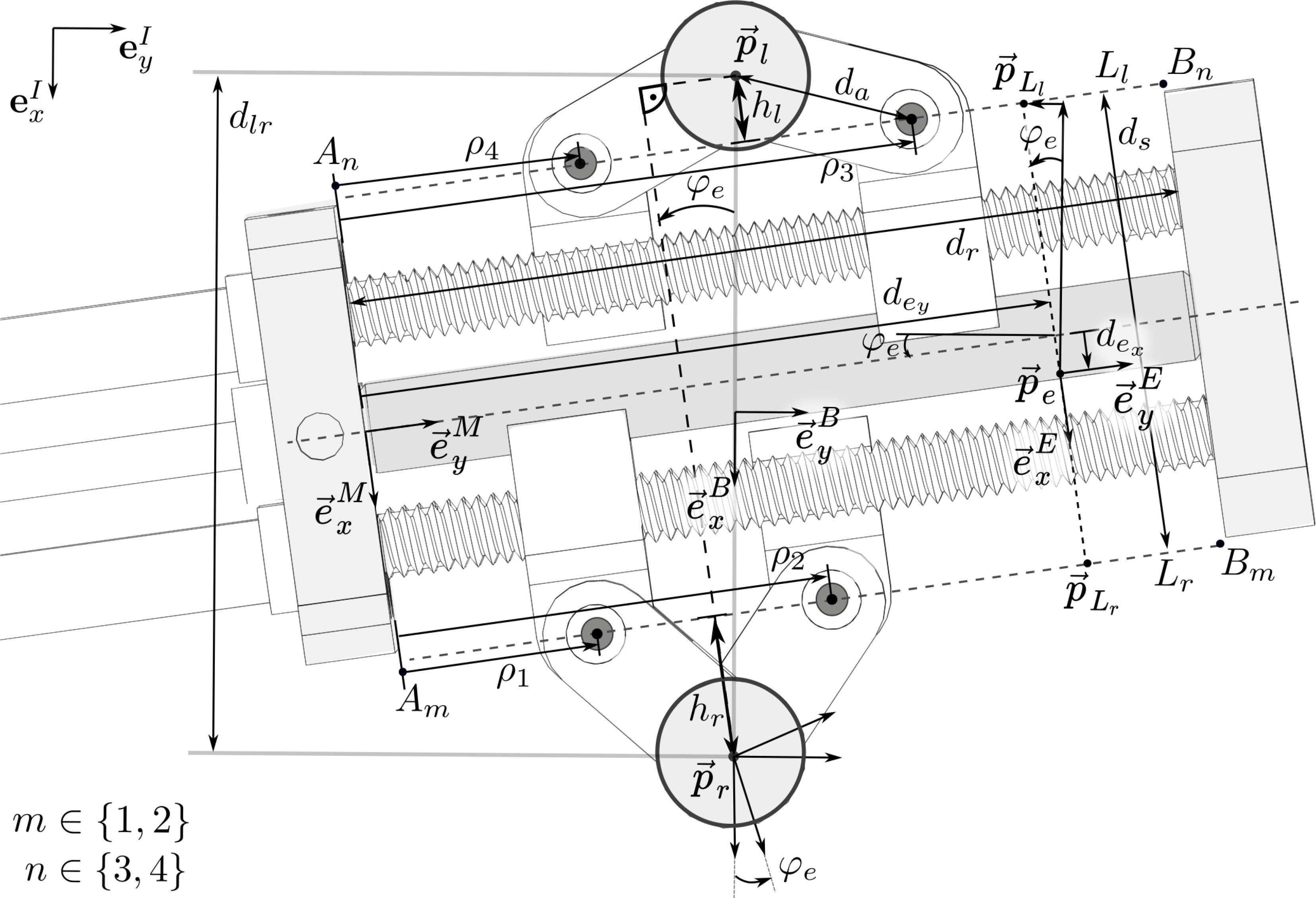
The definitions of the notation used in the following are illustrated in Fig. 5. The parameters $h_l$
and
$h_l$
and $h_r$
denote the distances between the left and right legs, respectively, and the connecting line between the two rotational joints around which the arms connected to the corresponding leg rotate. These parameters can be calculated based on the joint positions and the arm length
$h_r$
denote the distances between the left and right legs, respectively, and the connecting line between the two rotational joints around which the arms connected to the corresponding leg rotate. These parameters can be calculated based on the joint positions and the arm length $d_a$
, as follows:
$d_a$
, as follows:
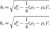 \begin{equation}\begin{aligned}h_l &= \sqrt{d_a^2-\frac{1}{4}(\rho_3-\rho_4)^2}, \\[3pt] h_r &= \sqrt{d_a^2-\frac{1}{4}(\rho_2-\rho_1)^2}.\end{aligned}\end{equation}
These parameters are used to calculate the direct and inverse kinematics of the parallel robot in the following sections. The direct kinematics are presented in previous work [Reference Eugster, Cattin, Zam and Rauter51]. For the inverse kinematics, a new derivation is formulated that facilitates the workspace calculation.
2.4.1. Direct kinematics
The position and orientation of the end effector, $ \left\lbrace x_e, y_e , \varphi_e \right\rbrace$
, given a specific configuration
$ \left\lbrace x_e, y_e , \varphi_e \right\rbrace$
, given a specific configuration $\vec{\rho}$
of the robot, can be calculated based on the distance between the right anchor point and the end-effector position in the end-effector frame as follows:
$\vec{\rho}$
of the robot, can be calculated based on the distance between the right anchor point and the end-effector position in the end-effector frame as follows:
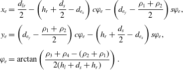 \begin{equation}\begin{aligned}x_e &= \frac{d_{lr}}{2}- \left( h_r +\frac{d_s}{2}-d_{e_x} \right) c\varphi_e- \left(d_{e_y}-\frac{\rho_1+\rho_2}{2} \right) s\varphi_e, \\[3pt] y_e &= \left( d_{e_y}-\frac{\rho_1+\rho_2}{2} \right) c\varphi_e - \left( h_r +\frac{d_s}{2}-d_{e_x} \right) s\varphi_e,\\[3pt] \varphi_e &= \arctan\left(\frac{\rho_3 + \rho_4 - (\rho_2 + \rho_1)}{2(h_l+d_s+h_r)}\right).\end{aligned}\end{equation}
Alternatively, the direct kinematics can also be calculated based on the distance between the left anchor point and the end-effector position, see Appendix B.
2.4.2. Inverse kinematics
To calculate the joint coordinates $\vec{\rho}$
based on a known end-effector pose
$\vec{\rho}$
based on a known end-effector pose $\vec{\chi}_e$
, we can rearrange the direct kinematic equations to obtain
$\vec{\chi}_e$
, we can rearrange the direct kinematic equations to obtain
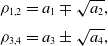 \begin{equation}\begin{aligned}\rho_{1,2} &= a_1 \mp \sqrt{a_2},\\[3pt] \rho_{3,4} &= a_3 \pm \sqrt{a_4},\end{aligned}\end{equation}
where
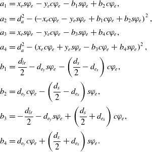 \begin{align}a_1 &= x_e s\varphi_e -y_e c\varphi_e - b_1 s\varphi_e + b_2 c\varphi_e, \nonumber\\[2pt] a_2 & = d_a^2-\left(\!-x_e c\varphi_e - y_e s\varphi_e + b_1 c\varphi_e + b_2 s\varphi_e\right)^2,\nonumber\\[2pt] a_3 &= x_e s\varphi_e -y_e c\varphi_e - b_3 s\varphi_e + b_4 c\varphi_e,\nonumber\\[2pt] a_4 & = d_a^2-\left(x_e c\varphi_e+y_e s\varphi_e-b_3 c\varphi_e+b_4 s\varphi_e\right)^2,\nonumber\\[2pt] b_1 &= \frac{d_{lr}}{2}-d_{e_y} s\varphi_e-\left(\frac{d_{s}}{2}-d_{e_x}\right) c\varphi_e, \\[2pt] b_2 &= d_{e_y} c\varphi_e-\left(\frac{d_{s}}{2}-d_{e_x}\right) s\varphi_e, \nonumber\\[2pt] b_3 &= -\frac{d_{lr}}{2}-d_{e_y} s\varphi_e+\left(\frac{d_{s}}{2}+d_{e_x}\right) c\varphi_e, \nonumber\\[2pt] b_4 &= d_{e_y} c\varphi_e+\left(\frac{d_{s}}{2}+d_{e_x}\right) s\varphi_e.\nonumber\end{align}
We define $\rho_1$
and
$\rho_1$
and $\rho_4$
as the position of the nuts that are closer to the origin of the frame M on the moving platform (see Fig. 5). More details on the derivation of the inverse kinematics is provided in Appendix B.
$\rho_4$
as the position of the nuts that are closer to the origin of the frame M on the moving platform (see Fig. 5). More details on the derivation of the inverse kinematics is provided in Appendix B.
2.5. Workspace
The parallel robot has three DoFs; two correspond to translational motion, $ \left\lbrace \vec{e}^I_x, \vec{e}^I_y \right\rbrace$
, and one corresponds to rotational motion,
$ \left\lbrace \vec{e}^I_x, \vec{e}^I_y \right\rbrace$
, and one corresponds to rotational motion, $\varphi_e$
. For each point
$\varphi_e$
. For each point $\left\lbrace x_e,y_e \right\rbrace$
that is part of the robot’s workspace, there is at least one nonempty interval for the angle
$\left\lbrace x_e,y_e \right\rbrace$
that is part of the robot’s workspace, there is at least one nonempty interval for the angle $\varphi_e$
. The workspace of the robot is restricted by various factors, such as the mechanical limits of the passive joints, self-collision between the elements of the robot, and limitations due to actuators and singularities [Reference Merlet58]. Based on the constraints that limit the robot’s movement, the robot’s workspace can be calculated. For a specified robot position
$\varphi_e$
. The workspace of the robot is restricted by various factors, such as the mechanical limits of the passive joints, self-collision between the elements of the robot, and limitations due to actuators and singularities [Reference Merlet58]. Based on the constraints that limit the robot’s movement, the robot’s workspace can be calculated. For a specified robot position $\left\lbrace x_e,y_e \right\rbrace$
, we can obtain exactly the rotational workspace as a set of intervals. The constraints that limit the robot’s workspace and the procedure to calculate the rotational workspace for a known robot position
$\left\lbrace x_e,y_e \right\rbrace$
, we can obtain exactly the rotational workspace as a set of intervals. The constraints that limit the robot’s workspace and the procedure to calculate the rotational workspace for a known robot position $\left\lbrace x_e,y_e \right\rbrace$
are described in the following.
$\left\lbrace x_e,y_e \right\rbrace$
are described in the following.
The first constraint is based on the condition that the inverse kinematic equations (11) must yield a real-valued solution for the square roots. Therefore, the values under the square roots must be larger than or equal to zero:
 \begin{equation}\begin{aligned}a_2 \geq 0 \quad \text{and} \quad a_4 \geq 0.\end{aligned}\end{equation}
Furthermore, there is a mechanical constraint that requires that the anchor points must be beside the moving platform and cannot be below it, since this would lead to collision between the arms and the leadscrews. To formulate this constraint, we introduce additional variables as follows. The lines $L_r$
and
$L_r$
and $L_l$
represent the supporting links
$L_l$
represent the supporting links $\left\lbrace A_1 B_1, A_2 B_2 \right\rbrace$
and
$\left\lbrace A_1 B_1, A_2 B_2 \right\rbrace$
and $\left\lbrace A_3 B_3, A_4 B_4 \right\rbrace$
:
$\left\lbrace A_3 B_3, A_4 B_4 \right\rbrace$
:
 \begin{equation}\begin{aligned}L_{l,r} \left( x,y \right) |y &= m x +n_{l,r}.\end{aligned}\end{equation}
The slope m of these lines can be calculated as
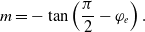 \begin{equation}\begin{aligned}m = - \tan\left(\frac{\pi}{2} - \varphi_e\right).\end{aligned}\end{equation}
The y-intercepts of the lines $L_{l,r}$
in the B frame can be calculated by inserting the points
$L_{l,r}$
in the B frame can be calculated by inserting the points $\{ _{B} \vec{p}_{L_l}, _{B}\vec{p}_{L_r}\}$
into the line equations defined in (14), which leads to
$\{ _{B} \vec{p}_{L_l}, _{B}\vec{p}_{L_r}\}$
into the line equations defined in (14), which leads to
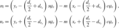 \begin{equation}\begin{aligned}n_l = \left(y_e - \left(\frac{d_{s}}{2}+d_{e_x}\right) s\varphi_e \right) -m\left(x_e - \left(\frac{d_{s}}{2}+d_{e_x}\right) c\varphi_e\right),\\[3pt] n_r = \left(y_e + \left(\frac{d_{s}}{2}-d_{e_x}\right) s\varphi_e \right) -m\left(x_e + \left(\frac{d_{s}}{2}-d_{e_x}\right) c\varphi_e\right).\end{aligned}\end{equation}
The constraint that the positions of the legs must be beside the moving platform and cannot be below it can be formulated by limiting the x-intercept of the line $L_l$
in the B frame to be located on the right side of the left anchor point and the x-intercept of the line
$L_l$
in the B frame to be located on the right side of the left anchor point and the x-intercept of the line $L_r$
on the right side of the robot to be located on the left side of the right anchor point:
$L_r$
on the right side of the robot to be located on the left side of the right anchor point:
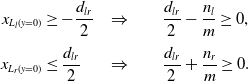 \begin{equation}\begin{aligned}x_{L_l(y = 0)} &\geq -\frac{d_{lr}}{2} &\Rightarrow & \qquad\frac{d_{lr}}{2}-\frac{n_l}{m} \geq 0, \\[3pt] x_{L_r(y = 0)} &\leq \frac{d_{lr}}{2} &\Rightarrow & \qquad \frac{d_{lr}}{2}+\frac{n_r}{m} \geq 0.\end{aligned}\end{equation}
The robot has two relevant singular configurations, which correspond to the cases in which the arms are parallel on one side of the robot. The first configuration occurs when the nuts are separated by the maximal distance and the second occurs when the nuts are in the same position and the arms are coincident. The closeness to such a singularity can be limited by specifying limits on the variables $h_r$
and
$h_r$
and $h_l$
. These variables denote the distances between the right and left legs, respectively, and the connecting line between the two rotational joints around which the arms connected to the corresponding leg rotate. This constraint results in four inequalities:
$h_l$
. These variables denote the distances between the right and left legs, respectively, and the connecting line between the two rotational joints around which the arms connected to the corresponding leg rotate. This constraint results in four inequalities:
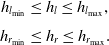 \begin{equation}\begin{aligned}h_{l_{\min}} &\leq h_l \leq h_{l_{\max}}, \\[3pt] h_{r_{\min}} &\leq h_r \leq h_{r_{\max}}.\end{aligned}\end{equation}
In addition, the actuator strokes are limited, meaning that the nut positions $\rho_i$
are bounded:
$\rho_i$
are bounded:
 \begin{equation}\begin{aligned}\rho_i \in \left[\rho_{\min},\rho_{\max}\right] \quad \forall i \in \left\lbrace 1,2,3,4 \right\rbrace.\end{aligned}\end{equation}
Note that based on the inverse kinematics Eqs. (11), the actuators are further constrained such that $\rho_1\ \leq\ \rho_2$
and
$\rho_1\ \leq\ \rho_2$
and $\rho_4\ \leq\ \rho_3$
, respectively.
$\rho_4\ \leq\ \rho_3$
, respectively.
Based on these constraints, the robot’s rotational workspace can be calculated using interval arithmetic. More exactly, the end effector is at the workspace border if any of the inequality variables (13), (17), (18), or (19) reaches its limit. By investigating the edge case of each inequality equation, we can find the border of the workspace. Each of the edge case equalities can be transformed into second order polynomials in T using the Weierstrass substitution
 \begin{equation}\begin{aligned}\sin(\varphi_e) = \frac{2T}{1+T^2}, \quad \cos(\varphi_e) = \frac{1-T^2}{1+T^2}. \end{aligned}\end{equation}
The real-valued roots $T_{{r}_j}$
of all 16 edge case polynomials are calculated and stored in a value sorted list. A value smaller than the first entry and a value bigger than the last entry are appended at the beginning and end of the list, respectively. This sorted root list forms the intervals that must be checked to be part of the reachable workspace. For each interval
$T_{{r}_j}$
of all 16 edge case polynomials are calculated and stored in a value sorted list. A value smaller than the first entry and a value bigger than the last entry are appended at the beginning and end of the list, respectively. This sorted root list forms the intervals that must be checked to be part of the reachable workspace. For each interval $\left[ T_{{r}_j}, T_{{r}_{j+1}} \right]$
, the midpoint is calculated as
$\left[ T_{{r}_j}, T_{{r}_{j+1}} \right]$
, the midpoint is calculated as $T_{mid_j} = (T_{{r}_j}+T_{{r}_{j+1}})/2$
, and at this midpoint, the inequality variables (13), (17), (18), and (19) are tested. If none of the inequalities is violated, then the interval
$T_{mid_j} = (T_{{r}_j}+T_{{r}_{j+1}})/2$
, and at this midpoint, the inequality variables (13), (17), (18), and (19) are tested. If none of the inequalities is violated, then the interval $\left[ T_{{r}_j}, T_{{r}_{j+1}} \right]$
is part of the reachable rotational workspace; otherwise, the interval is discarded. The resulting boundaries of the reachable rotational workspace are translated back into bounds on the angle
$\left[ T_{{r}_j}, T_{{r}_{j+1}} \right]$
is part of the reachable rotational workspace; otherwise, the interval is discarded. The resulting boundaries of the reachable rotational workspace are translated back into bounds on the angle $\varphi_e$
by using the transformation
$\varphi_e$
by using the transformation $\left[ \varphi_{e_{j}}, \varphi_{e_{j+1}} \right]= 2\arctan(\left[ T_{{r}_j}, T_{{r}_{j+1}} \right])$
. This procedure yields the set of valid intervals of the rotation angle
$\left[ \varphi_{e_{j}}, \varphi_{e_{j+1}} \right]= 2\arctan(\left[ T_{{r}_j}, T_{{r}_{j+1}} \right])$
. This procedure yields the set of valid intervals of the rotation angle $\varphi_e$
for each end-effector point
$\varphi_e$
for each end-effector point $\left\lbrace x_e,y_e \right\rbrace$
. Each point
$\left\lbrace x_e,y_e \right\rbrace$
. Each point $\left\lbrace x_e,y_e \right\rbrace$
for which there exists at least one nonempty interval for
$\left\lbrace x_e,y_e \right\rbrace$
for which there exists at least one nonempty interval for $\varphi_e$
is part of the translational workspace.
$\varphi_e$
is part of the translational workspace.
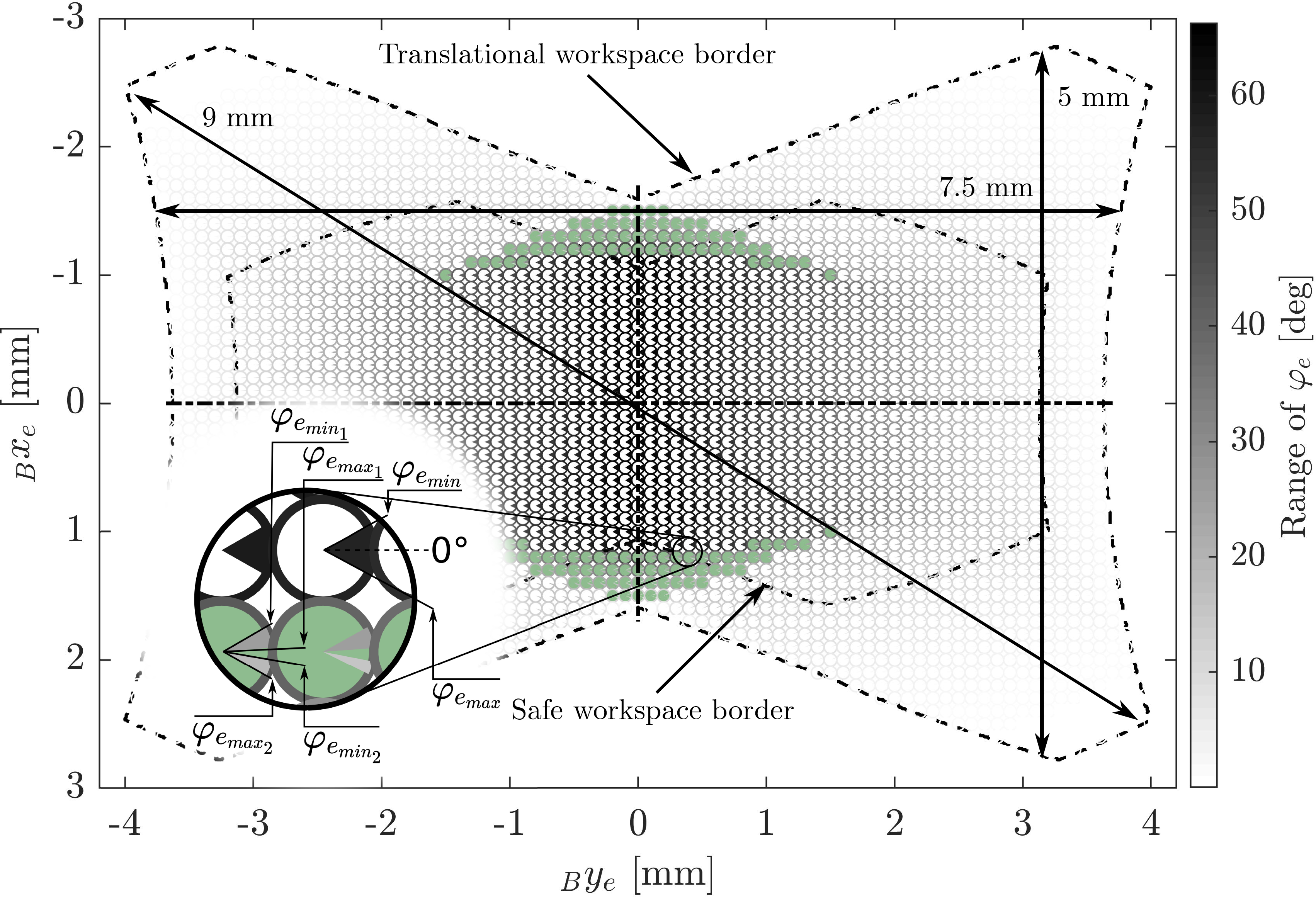
The geometrical parameters of the robot directly influence the shape and size of the workspace. For the prototype that is described in this work, we selected these parameters based on a compromise between minimizing the dimensions of the prototype, maximizing the resulting translational workspace of the robot, and simplifying the manufacturing and assembly process while reducing production costs. For that purpose, the translational workspace was calculated for all feasible parameter sets, and the set that resulted in the largest translational workspace was selected. The resulting workspace of the miniature robot for the geometrical parameters $d_s = {7.8}\,\text{mm}, d_a = {3}\,\text{mm}, d_{lr} = {11.5} \mathrm{mm}, d_{e_x} = {0}\mathrm{mm}$
and
$d_s = {7.8}\,\text{mm}, d_a = {3}\,\text{mm}, d_{lr} = {11.5} \mathrm{mm}, d_{e_x} = {0}\mathrm{mm}$
and $d_{e_y} = {7}\,\mathrm{mm}$
and constraints of
$d_{e_y} = {7}\,\mathrm{mm}$
and constraints of $\rho_{\min} = {0}\,\mathrm{mm},\rho_{\max} = {13}\,\mathrm{mm}, h_{{l,r}_{\min}} = {0}\,\mathrm{mm}, $
and
$\rho_{\min} = {0}\,\mathrm{mm},\rho_{\max} = {13}\,\mathrm{mm}, h_{{l,r}_{\min}} = {0}\,\mathrm{mm}, $
and $h_{{l,r}_{\max}} = {3}\,\mathrm{mm}$
is shown in Fig. 6.
$h_{{l,r}_{\max}} = {3}\,\mathrm{mm}$
is shown in Fig. 6.
The robot’s translational and rotational workspace: The rotational workspace range is shown by the marked section of the circle at each corresponding position in the translational workspace. The gray values of the circle sections encode the range of the feasible angle. The gray value of the circle border encodes the total size of the feasible angle range at that position. The filled green circles mark locations where the valid interval for $\varphi_e$
consists of two disjoint intervals. The arrows indicate the maximal straight cut lines in the workspace: vertical, horizontal, and overall.
$\varphi_e$
consists of two disjoint intervals. The arrows indicate the maximal straight cut lines in the workspace: vertical, horizontal, and overall.
3. Apparatus
3.1. Hardware design
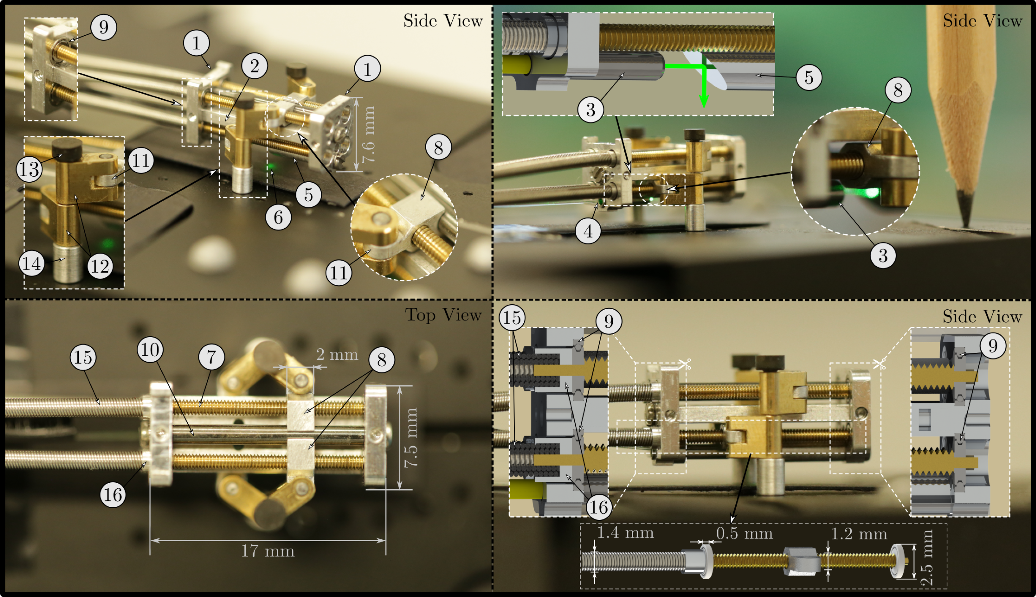
The hardware of the miniature parallel robot prototype consisted of a housing, which held the optical components for the laser, four drivetrains, which enabled the linear movement of the nuts along the leadscrews, and two legs, which connected the two arms on each side of the robot to the ground (Fig. 7). The movement of the nuts was enabled by the leadscrews (standard M1.2 thread), which transformed rotary motion into linear motion. The leadscrews were mounted in the housing via ball bearings (SD 1425XZRY, MPS Microsystems, Biel–Bienne, Switzerland). The rotation of the nuts was constrained by the leg structure and a guiding rod. The leg structure aligned the orientation of the two nuts on each side of the mechanism, while the rod constrained the orientation of the upper two nuts. The legs were constructed based on ejector pins with a diameter of 1 mm, which could be mounted in drill holes on a ground plate. The distance to the ground was defined by an aluminum socket. The rotary motion was generated by extrinsic electrical motors and was transmitted to the endoscope tip segment by flexible shafts (Schmid & Wezel GmbH, Sinsheim, Germany) with an outer diameter of 1.4 mm and a length of 325 mm. These flexible shafts were constructed of steel wire ( $\phi$
0.2 mm), wound into coils, alternately twisted in the right or left direction. This construction provides torsional stiffness while maintaining bending flexibility. The minimal bending radius of the flexible shafts was approximately 20 mm, and their dynamic torque capacity in both directions of rotation was estimated to be 5Ncm. Due to the manufacturing technique, each flexible shaft had a hollow core (
$\phi$
0.2 mm), wound into coils, alternately twisted in the right or left direction. This construction provides torsional stiffness while maintaining bending flexibility. The minimal bending radius of the flexible shafts was approximately 20 mm, and their dynamic torque capacity in both directions of rotation was estimated to be 5Ncm. Due to the manufacturing technique, each flexible shaft had a hollow core ( $\phi$
0.6 mm), which was used to mount it on the leadscrew. Since there is not sufficient space to implement interlocking mechanisms such as keys or screws, each leadscrew was glued inside the corresponding flexible shaft. The laser optics inside the prototype consisted of a ferrule (SFLC127-10, Thorlabs Inc., Newton, NJ, USA) holding the laser fiber (FG105LCA, Thorlabs Inc., Newton, NJ, USA), which guided the laser beam from the source to the miniature parallel robot. Shortly after the laser beam exited the fiber, the laser was redirected toward the surface below by a small mirror mounted on the robot’s distal endplate. The mirror consisted of an aluminum cylinder with a reflective surface tilted at 45
$\phi$
0.6 mm), which was used to mount it on the leadscrew. Since there is not sufficient space to implement interlocking mechanisms such as keys or screws, each leadscrew was glued inside the corresponding flexible shaft. The laser optics inside the prototype consisted of a ferrule (SFLC127-10, Thorlabs Inc., Newton, NJ, USA) holding the laser fiber (FG105LCA, Thorlabs Inc., Newton, NJ, USA), which guided the laser beam from the source to the miniature parallel robot. Shortly after the laser beam exited the fiber, the laser was redirected toward the surface below by a small mirror mounted on the robot’s distal endplate. The mirror consisted of an aluminum cylinder with a reflective surface tilted at 45 ${^\circ}$
. The laser source was a diode laser (CPS532, Thorlabs Inc., Newton, NJ, USA) producing 4.5 mW output at 532 nm for visualization purposes.
${^\circ}$
. The laser source was a diode laser (CPS532, Thorlabs Inc., Newton, NJ, USA) producing 4.5 mW output at 532 nm for visualization purposes.
The manufactured prototype of the parallel robot for laser positioning and stabilization: The housing of the device consists of two endplates (1) and a connection plate (2) made of aluminum. A ferrule (3), which holds the optical fiber (4), is mounted on the proximal endplate. The distal endplate holds a small mirror (5), which redirects the laser (6) toward the surface below the robot. The four drivetrains each consist of a leadscrew (7) and a nut (8), which can travel along the leadscrew as it rotates. The leadscrews are mounted on both endplates via ball bearings (9). The upper nuts are guided by a rod (10) mounted between the two endplates. Each nut contains a rotary joint (11), which holds one of the robots arms (12). The two arms on each side of the robot are mounted on the corresponding leg (13) by means of rotational slide bearings. The distance to the ground plate is defined by aluminum sockets (14). The leadscrews are connected to flexible shafts (15) using glue. A small aluminum coupling (16) houses the flexible shaft and prevents the glue from entering the bearing.
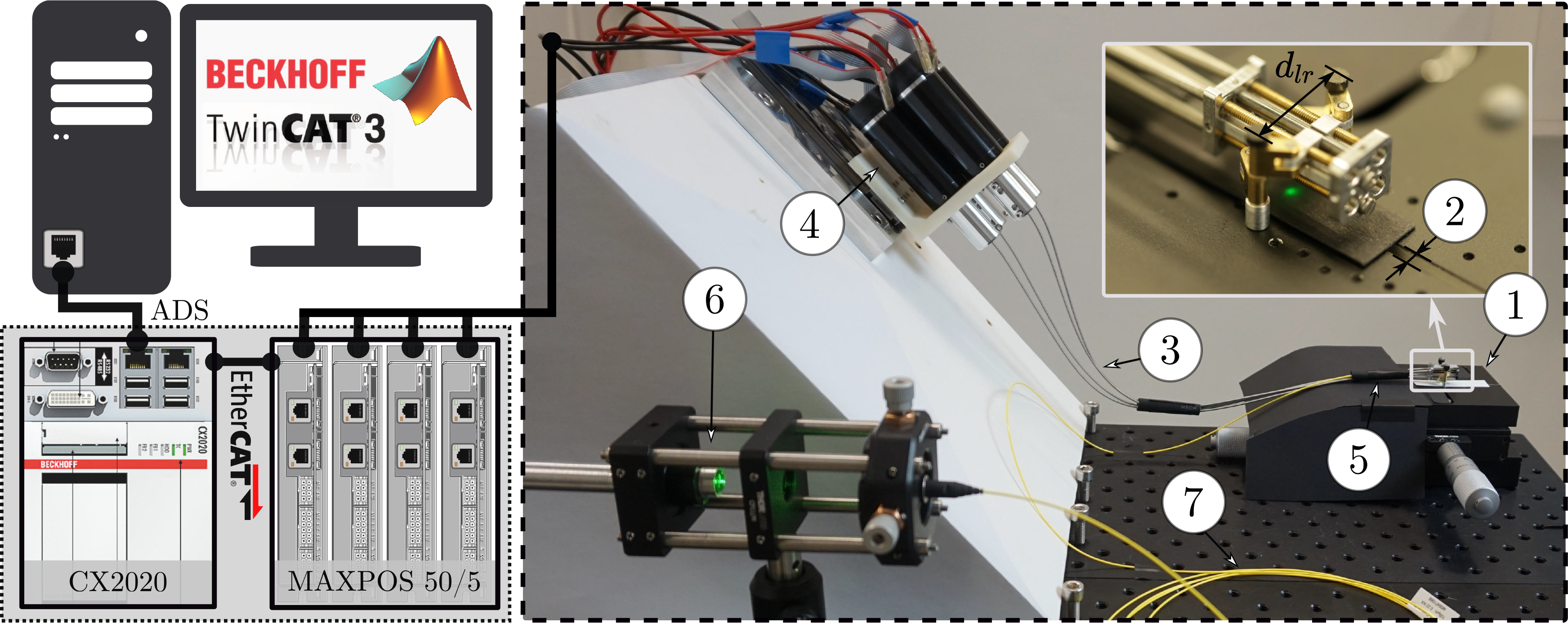
The robot was mounted on a ground plate, which consisted of two separate plates connected by two pins. This setting allowed the distance between the two plates to be continuously varied while they remained parallel, thus allowing the mounting distance between the robot’s legs, $d_{lr}$
, to be adjusted (Fig. 8). The movement of the robot was actuated by four flexible shafts connected to DC motors (
$d_{lr}$
, to be adjusted (Fig. 8). The movement of the robot was actuated by four flexible shafts connected to DC motors ( $\phi$
25 mm, 263,349, Maxon Motor AG, Sachseln, Switzerland) using aluminum couplings. On the robot side, the flexible shafts were connected to leadscrews, which transformed the rotary motion of the motors into linear movements of the nuts and, thus, of the parallel robot’s joints. The system is controlled by TwinCAT 3 automation software running on a real-time CPU module (CX2020, Beckhoff Automation GmbH & Co. KG, Verl, Germany) (Fig. 8). The motors were driven by positioning controllers (MAXPOS 50/5, Maxon Motor AG). Using the Simulink Coder software suite (MathWorks, MA, USA), Simulink models could be compiled and integrated into the TwinCAT 3 environment. A graphical user interface was implemented (App designer from MATLAB R2018b, MathWorks), which communicated with the CPU module and enabled the user to define a reference path in the operational space to be followed by the parallel robot. The CPU module controlled the motor drives via EtherCAT. The App Designer from MATLAB has been used to implement a graphical user interface on the developer computer that enabled high-level control via a device- and fieldbus- independent interface (Automation Device Specification, ADS).
$\phi$
25 mm, 263,349, Maxon Motor AG, Sachseln, Switzerland) using aluminum couplings. On the robot side, the flexible shafts were connected to leadscrews, which transformed the rotary motion of the motors into linear movements of the nuts and, thus, of the parallel robot’s joints. The system is controlled by TwinCAT 3 automation software running on a real-time CPU module (CX2020, Beckhoff Automation GmbH & Co. KG, Verl, Germany) (Fig. 8). The motors were driven by positioning controllers (MAXPOS 50/5, Maxon Motor AG). Using the Simulink Coder software suite (MathWorks, MA, USA), Simulink models could be compiled and integrated into the TwinCAT 3 environment. A graphical user interface was implemented (App designer from MATLAB R2018b, MathWorks), which communicated with the CPU module and enabled the user to define a reference path in the operational space to be followed by the parallel robot. The CPU module controlled the motor drives via EtherCAT. The App Designer from MATLAB has been used to implement a graphical user interface on the developer computer that enabled high-level control via a device- and fieldbus- independent interface (Automation Device Specification, ADS).
Hardware and software framework: The developer computer runs TwinCAT 3 and enables programming of the real-time CPU module (CX2020) which controls the motor drives via EtherCAT. A graphical user interface on the developer computer enables high-level control via a device- and fieldbus-independent interface (Automation Device Specification, ADS). The robot is mounted on a ground plate (1) that allows adjustment (2) of the mounting distance between the robot’s legs, $d_{lr}$
. The flexible shafts (3) driving the robot are connected to four Maxon DC motors (4) mounted on a tilted plate. A rubber tube (5), which represents the endoscope shaft, constrains the flexible shafts to pass through a cylinder before reaching the parallel robot. A diode laser (6) is coupled into a fiber (7) and guided to the robot.
$d_{lr}$
. The flexible shafts (3) driving the robot are connected to four Maxon DC motors (4) mounted on a tilted plate. A rubber tube (5), which represents the endoscope shaft, constrains the flexible shafts to pass through a cylinder before reaching the parallel robot. A diode laser (6) is coupled into a fiber (7) and guided to the robot.
3.2. Control
The cutting process will be based on pointwise ablation by a pulsed laser. Therefore, it is not necessary to realize continuous accurate movement of the laser; it is merely necessary to ensure that each ablation point along the desired cut can be reached with the desired accuracy. Each laser pulse is triggered only when the parallel robot has positioned the laser at the correct location, that is, has reduced the error in the operational space, $\Delta_{{xy}_{control}}$
, below a specified threshold,
$\Delta_{{xy}_{control}}$
, below a specified threshold, $\delta_{xy_{\max}}$
. The desired cut was specified as a path, which we defined offline as a series of end-effector poses with a defined order but without a time variable.
$\delta_{xy_{\max}}$
. The desired cut was specified as a path, which we defined offline as a series of end-effector poses with a defined order but without a time variable.
Based on the desired path in the operational space defined by the user, the corresponding sequence of joint positions was calculated using inverse kinematics. This joint position sequence was sent to the real-time system, where the control scheme was executed in real time with an update rate of 1 kHz. The control scheme consisted of two subcontrollers: first, a path controller decided whether to advance along the path and second, a proportional gain controller set the velocity for each motor based on the differences between the desired joint positions and the actual joint positions (Fig. 9). This controller used the sensor feedback from the motor encoders that actuated the flexible shafts.
The control structure of the parallel robot: A desired path is defined offline. The control system then regulates the movement of the robot based on the position feedback from the motor encoders. For experimental evaluation, the actual position of the robot is measured using a tracking system. $\textbf{P}_{des}$
: desired joint position sequence,
$\textbf{P}_{des}$
: desired joint position sequence, $\delta_{xy_{\max}}$
: position error threshold,
$\delta_{xy_{\max}}$
: position error threshold, $\delta_{\rho_{\max}}$
: joint error threshold,
$\delta_{\rho_{\max}}$
: joint error threshold, $\vec{v}_{m}$
: desired motor velocity,
$\vec{v}_{m}$
: desired motor velocity, $\vec{\alpha}$
: angular motor positions.
$\vec{\alpha}$
: angular motor positions.
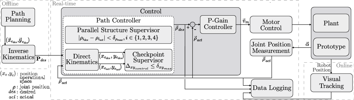
The path controller consisted of two different instances that decided when the next point along the path would be set as the desired position: a parallel structure supervisor and a checkpoint supervisor. The parallel structure supervisor had higher priority, was implemented in the joint space, and ensured that advancement along the path was allowed only when the absolute error between the desired and actual joint positions was below a certain threshold $\delta_{\rho_{\max}}$
for all four joints:
$\delta_{\rho_{\max}}$
for all four joints:
 \begin{equation}\begin{aligned}|\rho_{i_{act}}-\rho_{i_{des}}| < \delta_{\rho_{\max}} \quad \forall i \in \left\lbrace 1,2,3,4 \right\rbrace.\end{aligned}\end{equation}
This supervision was necessary since the parallel robot is overactuated and the four prismatic joints (the nuts on the leadscrews) must move synchronously to avoid introducing strain on the robot. The checkpoint supervisor operated at a lower priority, was implemented in the operational space, and permitted the user to define checkpoints along the path at which the error between the desired and actual positions in the operational space, $\Delta_{{xy}_{control}}$
, must satisfy a specified threshold,
$\Delta_{{xy}_{control}}$
, must satisfy a specified threshold, $\delta_{xy_{\max}}$
, before advancement along the path was allowed:
$\delta_{xy_{\max}}$
, before advancement along the path was allowed:
 \begin{equation}\begin{aligned}\Delta_{{xy}_{control}} &= \sqrt{(x_{e_{des}}-x_{e_{act}})^2+(y_{e_{des}}-y_{e_{act}})^2} \\&< \delta_{xy_{\max}}.\end{aligned}\end{equation}
The actual and desired positions in the operational space were calculated based on the measured and desired joint positions using direct kinematics (Section 2.4). The direct kinematics was calculated starting from both the left and the right anchor points and the mean value was used as the calculated end-effector pose to reduce the influence of play, manufacturing inaccuracies, and measurement errors.
The resulting desired joint positions $\vec{\rho}_{des}$
were compared against the actual joint positions
$\vec{\rho}_{des}$
were compared against the actual joint positions $\vec{\rho}_{act}$
, and the proportional gain controller sent the corresponding velocity commands
$\vec{\rho}_{act}$
, and the proportional gain controller sent the corresponding velocity commands $\vec{v}_{m}$
to the motor drives. Based on the motor positions
$\vec{v}_{m}$
to the motor drives. Based on the motor positions $\vec{\alpha}$
measured by the encoders, the actual joint positions
$\vec{\alpha}$
measured by the encoders, the actual joint positions $\vec{\rho}_{act}$
were calculated in accordance with the thread pitch of the leadscrews. Safety limitations were imposed on the maximal velocity and torque values to avoid hardware damage. For performance evaluation of the device, the visual tracking system measured the actual position of the robot. The corresponding data were logged synchronously in real-time and postprocessed offline.
$\vec{\rho}_{act}$
were calculated in accordance with the thread pitch of the leadscrews. Safety limitations were imposed on the maximal velocity and torque values to avoid hardware damage. For performance evaluation of the device, the visual tracking system measured the actual position of the robot. The corresponding data were logged synchronously in real-time and postprocessed offline.
This control scheme enables the mechanism to follow a path and reach certain checkpoints on that path with the desired accuracy in operational space based on the encoder feedback of the motors that rotate the flexible shafts.
4. Accuracy Evaluation Experiment
4.1. Evaluation path
To enable the execution of a continuous cut employing a pointwise laser ablation scheme with a beam diameter of 0.5 mm, the robot must achieve a positioning accuracy below 0.25 mm in the xy-plane. A path-following experiment was performed in which the robot was controlled to move along a predefined path in the operational space. A subset of points along the path were selected for which the robot was controlled to reach an error below a threshold of $\delta_{xy_{\max}}\ \leq\ {0.01}\,\text{mm}$
for (22). For the performed experiment, the threshold
$\delta_{xy_{\max}}\ \leq\ {0.01}\,\text{mm}$
for (22). For the performed experiment, the threshold $\delta_{\rho_{\max}}$
of the parallel structure supervisor was set to 0.1 mm and the gain for the proportional controller was set to 20/s. These values were selected to establish a trade-off between limiting the duration of the path-following experiment and not impeding the performance of the parallel robot.
$\delta_{\rho_{\max}}$
of the parallel structure supervisor was set to 0.1 mm and the gain for the proportional controller was set to 20/s. These values were selected to establish a trade-off between limiting the duration of the path-following experiment and not impeding the performance of the parallel robot.
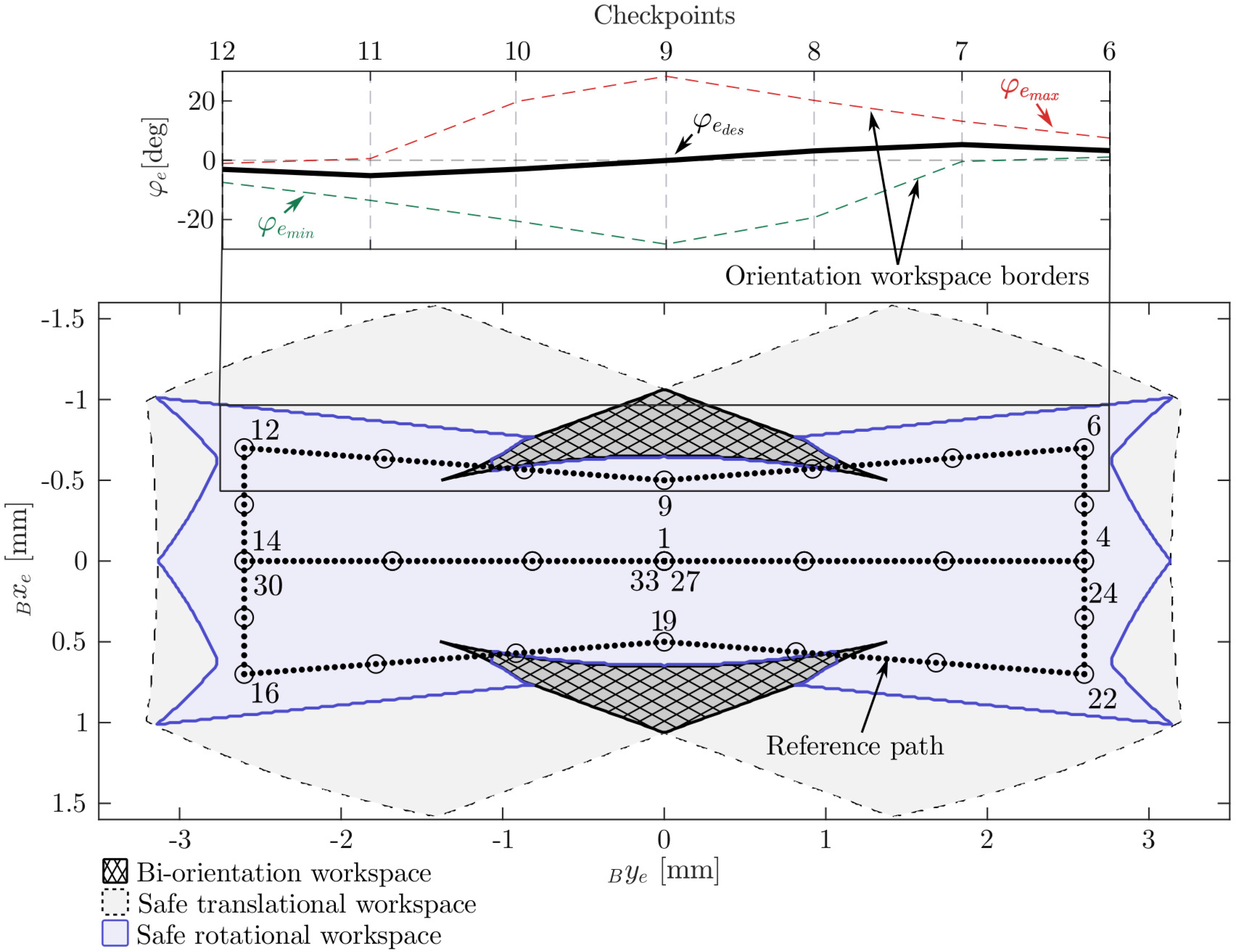
The reference path that was followed in this experiment was designed based on the shape of a subspace of the robot’s maximal reachable workspace that was defined to avoid working at the limits of the theoretically possible workspace (Fig. 10). The limits on the minimal and maximal joint positions were set to $\rho_{\min} = {1.5}\,\text{mm}$
and
$\rho_{\min} = {1.5}\,\text{mm}$
and $\rho_{\max} = {12.5}\,\text{mm}$
, respectively. The minimal and maximal distances from the leadscrews to the legs were limited to
$\rho_{\max} = {12.5}\,\text{mm}$
, respectively. The minimal and maximal distances from the leadscrews to the legs were limited to $h_{{l,r}_{\min}} = {0.5}\,\text{mm}$
and
$h_{{l,r}_{\min}} = {0.5}\,\text{mm}$
and $h_{{l,r}_{\max}} = {2.5}\,\text{mm}$
. In addition, the workspace was limited to the subspace in which the rotational workspace has a size of at least 6
$h_{{l,r}_{\max}} = {2.5}\,\text{mm}$
. In addition, the workspace was limited to the subspace in which the rotational workspace has a size of at least 6 ${^\circ}$
to avoid the workspace boundaries. The distance between adjacent points along the path in the xy-plane was set to 0.05 mm. Subsequently, the corresponding feasible rotational workspace was calculated for each point on the path as described in Section 2.5. The angle
${^\circ}$
to avoid the workspace boundaries. The distance between adjacent points along the path in the xy-plane was set to 0.05 mm. Subsequently, the corresponding feasible rotational workspace was calculated for each point on the path as described in Section 2.5. The angle $\varphi_{e_{des}}$
is not relevant to the laser cutting process since the laser is rotationally symmetric. However, the resulting path for
$\varphi_{e_{des}}$
is not relevant to the laser cutting process since the laser is rotationally symmetric. However, the resulting path for $\varphi_{e_{des}}$
must lie within the feasible rotational workspace, and the transition from one point on the path to the next must be possible with a continuous change in
$\varphi_{e_{des}}$
must lie within the feasible rotational workspace, and the transition from one point on the path to the next must be possible with a continuous change in $\varphi_{e_{des}}$
. Thus, the angle was selected to lie in the middle of the corresponding feasible range
$\varphi_{e_{des}}$
. Thus, the angle was selected to lie in the middle of the corresponding feasible range $\left[ \varphi_{e_{\min}}, \varphi_{e_{\max}}\right]$
. In addition, a moving average filter was applied to this path to smooth the resulting rotational reference path. The path started in the middle of the workspace, at
$\left[ \varphi_{e_{\min}}, \varphi_{e_{\max}}\right]$
. In addition, a moving average filter was applied to this path to smooth the resulting rotational reference path. The path started in the middle of the workspace, at $x_e = 0$
and
$x_e = 0$
and $y_e = 0$
. Checkpoints were placed at all edge points of the path. Further checkpoints were placed in between the path edge points (Fig. 10).
$y_e = 0$
. Checkpoints were placed at all edge points of the path. Further checkpoints were placed in between the path edge points (Fig. 10).
The path-following experiment: The reference path is located in the safe workspace and avoids the biorientation workspace (areas in which the rotational workspace consists of two disjoint subspaces). On the left, the orientation for checkpoints 6–12 and the orientation workspace borders are shown. The checkpoints are visualized as circles, and some are labeled in accordance with their order along the path.
4.2. Joint position measurement
The expected error on the calculated end-effector position based on the uncertainty of the joint position measurement was estimated for the prototype, as described in Section 2.3 (Eq. (3)). We estimated the backlash due to axial play of the leadscrew–nut pair to approximately ${0.01}\,\text{mm}$
. This estimate is based on measurements of axial movement of the leadscrew using a dial gauge, while the nut was fixed. With a leadscrew pitch of
${0.01}\,\text{mm}$
. This estimate is based on measurements of axial movement of the leadscrew using a dial gauge, while the nut was fixed. With a leadscrew pitch of $p = {0.25}\,\text{mm}$
, a maximal deformation of the flexible shafts of
$p = {0.25}\,\text{mm}$
, a maximal deformation of the flexible shafts of ${20}{^\circ}$
, and the limited resolution of the motors with 500 counts per revolution, we calculated
${20}{^\circ}$
, and the limited resolution of the motors with 500 counts per revolution, we calculated $U_{\rho_i} = {0.02}\,\text{mm}$
. To calculate the corresponding position error of the end effector, the end-effector pose error (Eq. (6)) was evaluated at each checkpoint on the path. The resulting expected error of the measured end-effector position
$U_{\rho_i} = {0.02}\,\text{mm}$
. To calculate the corresponding position error of the end effector, the end-effector pose error (Eq. (6)) was evaluated at each checkpoint on the path. The resulting expected error of the measured end-effector position $\Delta_{{xy}_{est}}$
due to the measurement uncertainty of the nut positions was calculated as follows:
$\Delta_{{xy}_{est}}$
due to the measurement uncertainty of the nut positions was calculated as follows:
 \begin{equation}\Delta_{{xy}_{est}} = \sqrt{\Delta{x_e}^2+\Delta{y_e}^2}.\end{equation}
4.3. Visual tracking
An external tracking system (Vicon Motion Systems, Oxford, United Kingdom) was used to evaluate the robot’s accuracy in the operational space. Reflective markers mounted on the robot were tracked by a camera system consisting of six Vicon Vantage V5 cameras (Vicon Motion Systems, Oxford, United Kingdom) mounted on tripods around the system setup. Reflective hemispherical markers were placed on the ground plate and on the parallel robot (Fig. 11). The tracked positions of the markers were acquired by a dedicated workstation running the tracking software (Nexus 2.8, Vicon Motion Systems). The tracked marker positions were forwarded to the real-time CPU module to synchronize the measured data. Since the robot moved with a relatively slow velocity, the delay of the tracking system was not relevant. The accuracy of the tracking system was assessed by analyzing the distances between the five stationary markers on the ground plate, the positions of which were fixed relative to each other. Over all performed measurements, the maximal deviation of a distance measurement from the corresponding mean value was in the range of $\pm17\mu {\text{m}}$
. Since our aim was to track the parallel robot in the submillimeter range, this measurement setup was considered sufficiently accurate.
$\pm17\mu {\text{m}}$
. Since our aim was to track the parallel robot in the submillimeter range, this measurement setup was considered sufficiently accurate.
4.4. Experimental procedure and data processing
Before the experiment started, the robot was calibrated by manually rotating the motor shafts such that the nuts reached the first endplate (Fig. 7). Then, the encoder values were calibrated accordingly.
Experimental setup: For performance evaluation using the tracking system, reflective hemispherical markers were mounted on the robot as well as on the ground plate. An aluminum plate (2) was mounted on top of the robot, which was used to host two markers ( $\phi$
3 mm) (3) to enable tracking of the end effector (
$\phi$
3 mm) (3) to enable tracking of the end effector ( $\vec{p}_e$
) and the orientation of the mobile platform (
$\vec{p}_e$
) and the orientation of the mobile platform ( $\varphi_e$
). Two further markers were mounted on the tops of the legs to track their movement during the experiment. Five hemispherical markers (
$\varphi_e$
). Two further markers were mounted on the tops of the legs to track their movement during the experiment. Five hemispherical markers ( $\phi$
4 mm) were placed on the ground plate to establish a reference coordinate frame I (4). The tracking information obtained by the motion capture cameras and corresponding software was forwarded to the real-time system via User Data Protocol (UDP).
$\phi$
4 mm) were placed on the ground plate to establish a reference coordinate frame I (4). The tracking information obtained by the motion capture cameras and corresponding software was forwarded to the real-time system via User Data Protocol (UDP).
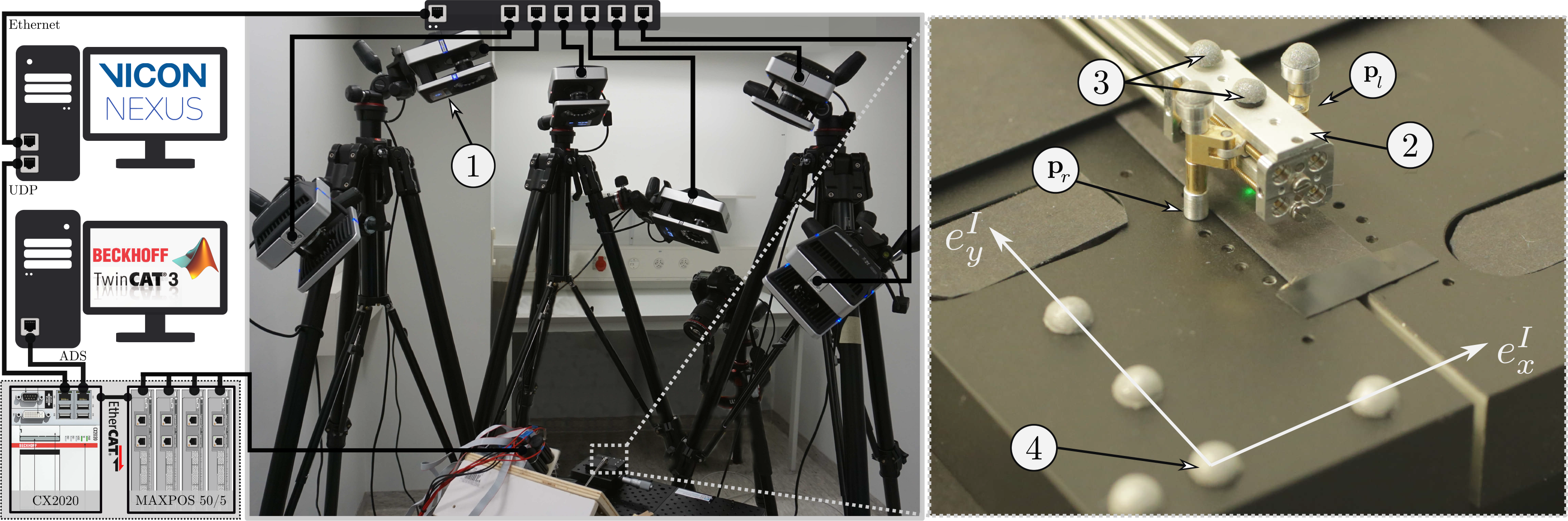
The robot was controlled to follow the reference path (Fig. 10) 10 times in alternating directions. For the reversed direction, the path was flipped around the y-axis. At the start of each run, the tracked end-effector position was zeroed.
The real-time system logged the tracked marker positions as well as the path controller information during the experiment in a synchronized manner for later evaluation. The data were postprocessed in MATLAB R2018b. The distances between the desired and tracked positions in the xy-plane in the operational space were calculated to evaluate the performance of the parallel robot:
 \begin{equation}\Delta_{{xy}_{tracked}} = \sqrt{(x_{e_{des}}-x_{e_{tracked}})^2+(y_{e_{des}}-y_{e_{tracked}})^2}.\end{equation}
As soon as the position error dropped below the threshold in accordance with (22), the advancement along the path was delayed for 2 s before the next checkpoint was set as the target position by the controller to assess the influence of noise on the measurement. The mean and maximal values of the tracked error over the static 2 s were calculated for each of the $N = 33$
checkpoints, and the 10 experiments. The mean value of the tracked error
$N = 33$
checkpoints, and the 10 experiments. The mean value of the tracked error $ \Delta_{{xy}_{mean}}$
allows to cancel out noise originating from the tracking system and the neglectable residual movement of the robot for a static reference. The maximal value of the tracked error
$ \Delta_{{xy}_{mean}}$
allows to cancel out noise originating from the tracking system and the neglectable residual movement of the robot for a static reference. The maximal value of the tracked error $\Delta_{{xy}_{\max}}$
is provided for completeness and to determine potential systematic errors of the tracking system. The average expected accuracy of the miniature parallel robot in the considered workspace is calculated as the grand average over all checkpoints and experimental runs
$\Delta_{{xy}_{\max}}$
is provided for completeness and to determine potential systematic errors of the tracking system. The average expected accuracy of the miniature parallel robot in the considered workspace is calculated as the grand average over all checkpoints and experimental runs $\left( k = 1,2,... 10 \cdot N \right)$
of the mean errors over the static 2 s at the checkpoints
$\left( k = 1,2,... 10 \cdot N \right)$
of the mean errors over the static 2 s at the checkpoints $avg_{k}(\Delta_{{xy}_{mean,k}})$
. The expected worst-case accuracy in the considered workspace is calculated as the maximum of the mean errors over the static 2 s at the checkpoints
$avg_{k}(\Delta_{{xy}_{mean,k}})$
. The expected worst-case accuracy in the considered workspace is calculated as the maximum of the mean errors over the static 2 s at the checkpoints $\max_{k}(\Delta_{{xy}_{mean,k}})$
. To allow stating a guaranteed accuracy, also the maximum of the maximal errors is provided
$\max_{k}(\Delta_{{xy}_{mean,k}})$
. To allow stating a guaranteed accuracy, also the maximum of the maximal errors is provided $\max_{k}(\Delta_{{xy}_{\max,k}})$
. The mean travel speed of the robot along the path between the checkpoints
$\max_{k}(\Delta_{{xy}_{\max,k}})$
. The mean travel speed of the robot along the path between the checkpoints $v_{e_{mean}}$
was calculated by dividing the distance of the desired path by the time of travel for each path segment between two checkpoints. The maximal value of the mean travel speed is calculated
$v_{e_{mean}}$
was calculated by dividing the distance of the desired path by the time of travel for each path segment between two checkpoints. The maximal value of the mean travel speed is calculated $\max_{k}(v_{e_{mean,k}})$
to provide an estimate of the robot’s maximal mean travel speed that was validated with the performed experiment.
$\max_{k}(v_{e_{mean,k}})$
to provide an estimate of the robot’s maximal mean travel speed that was validated with the performed experiment.
5. Results
5.1. Miniature parallel robot
The prototype of the miniature parallel robot was successfully manufactured and assembled. The implemented closed-loop control is functional and allows to follow a predefined path with the robot (video recording of the path-following experiment available in Supplementary material). The mobile platform of the device has a length of 17 mm, a height of 7.6 mm, and a width of 7.5 mm. The robot is designed such that it is oriented parallel to the bone surface, and thus, the required manipulation space above the target mainly depends on the height of the robot. The manufactured robot holds an optical fiber and a tilted mirror that deflects the laser light toward the surface below the robot. In the current design, the free space available for the laser optics and additional components such as an irrigation device is approximately $3.5 \times 2 \times {14}{{\rm mm}^3}$
. The robot enables manipulation of the laser in three planar DoFs.
$3.5 \times 2 \times {14}{{\rm mm}^3}$
. The robot enables manipulation of the laser in three planar DoFs.
The developed concept for accurate prismatic actuation with small dimensions was successfully implemented. Furthermore, the joint position measurement principle based on the encoders of the externally placed motors proved to be sufficient for the successful operation of the miniature robot. The actuation principle allows independent movement and position sensing of all four prismatic actuators inside the miniature robot.
5.2. Workspace
The maximal reachable workspace of the manufactured miniature parallel robot has an area of ${34}\,{{\rm mm}^2}$
. The maximal straight lines in the x- and y-directions have lengths of 5 mm and 7.5 mm, respectively. The longest straight line that can be placed in the workspace is 9 mm (Fig. 6).
${34}\,{{\rm mm}^2}$
. The maximal straight lines in the x- and y-directions have lengths of 5 mm and 7.5 mm, respectively. The longest straight line that can be placed in the workspace is 9 mm (Fig. 6).
5.3. Performance evaluation
The maximal expected uncertainty of the end-effector position, based on the modeled uncertainty of the nut position measurement, was calculated for each checkpoint along the path, as described in Section 4.2. The resulting lower bound for the achievable positioning accuracy was $\Delta_{{xy}_{est}} = {0.04}\,\text{mm}$
, which is below the target accuracy as required.
$\Delta_{{xy}_{est}} = {0.04}\,\text{mm}$
, which is below the target accuracy as required.
The miniature parallel robot was able to complete the path-following experiment presented in Section 4.1, in which the robot was controlled to guide the laser along a predefined path. The device followed the path with an average mean error of $avg_{k}(\Delta_{{xy}_{mean,k}})= {0.069}\,\text{mm}$
at the checkpoints. The maximal measured mean error at the checkpoints was
$avg_{k}(\Delta_{{xy}_{mean,k}})= {0.069}\,\text{mm}$
at the checkpoints. The maximal measured mean error at the checkpoints was $\max_{k} (\Delta_{{xy}_{mean,k}} ) = {0.17}\,\text{mm}$
. The overall maximal error at the checkpoints was
$\max_{k} (\Delta_{{xy}_{mean,k}} ) = {0.17}\,\text{mm}$
. The overall maximal error at the checkpoints was $\max_{k}(\Delta_{{xy}_{\max,k}}) = {0.176}\,\text{mm}$
(Fig. 12). The robot moved with a maximal forward speed along the path between two checkpoints of
$\max_{k}(\Delta_{{xy}_{\max,k}}) = {0.176}\,\text{mm}$
(Fig. 12). The robot moved with a maximal forward speed along the path between two checkpoints of $\max_{k}(v_{e_{mean,k}}) = {1.6}{{\rm mm}/{\rm min}}$
.
$\max_{k}(v_{e_{mean,k}}) = {1.6}{{\rm mm}/{\rm min}}$
.
Results of the path-following experiment: The robot followed a preplanned path 10 times. In this figure, the path data from the clockwise run are flipped around the y-axis such that the checkpoints coincide with the checkpoints of the counterclockwise run according to their numbering. The black point clouds represent the tracked positions during the time when the robot reached each checkpoint according to the criteria specified in the control scheme. The circles represent the maximal measured deviations at the checkpoints.
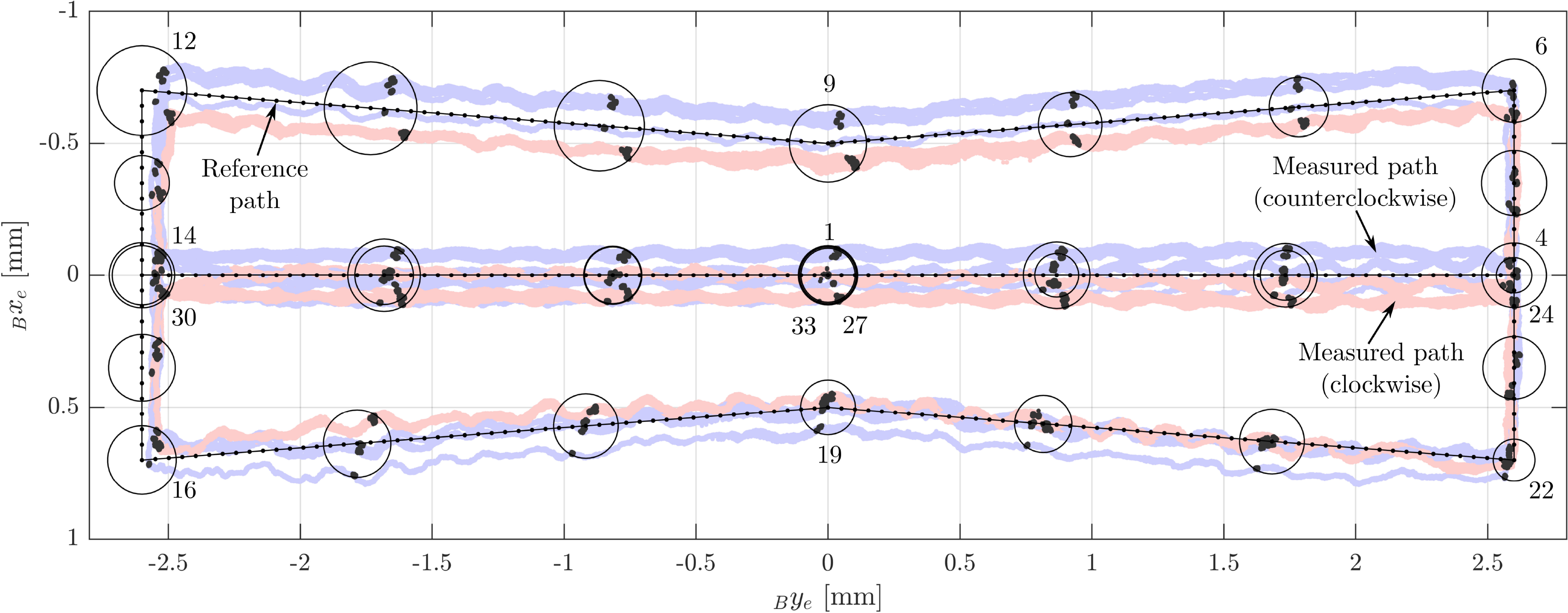
6. Discussion
The miniature parallel robot’s design is tuned for minimally invasive interventions in confined and narrow spaces since the device is oriented parallel to the target surface. Therefore, the required manipulation space above the target tissue mainly depends on the miniature parallel robot’s height. The dimensions of the manufactured prototype are close to the dimensions of standard tools used for knee arthroscopy, as the main body of the prototype has a height of 7.6 mm. This height is also below 8 mm, which is the upper boundary of the manipulation space’s thickness we expect to be available for a large portion of the cutting locations in minimally invasive UKA [Reference Eugster, Zoller, Krenn, Blache, Friederich, Müller-Gerbl, Cattin and Rauter20]. However, the prototype’s height of 7.6 mm does not include additional space that the mechanism’s legs may require. Therefore, further miniaturization might be required.
The design and actuation principle of the parallel robot allows the motors to be placed outside the device and does not require sensors inside the end effector. Therefore, the dimensions of the parallel robot can be further reduced by miniaturizing the mechanical components, for example, the leadscrew–nut pairs, the arms, and the leg structure. However, further miniaturization will, in turn, lead to additional or increased uncertainties, and the accuracy of such a miniaturized prototype would have to be reevaluated. For example, we expect the use of flexible shafts with even smaller dimensions to increase the uncertainties in the motion transmission. In addition, further miniaturization will require corresponding miniaturization of the integrated surgical tools.
The device was designed to allow large-area bone processing in a minimally invasive manner. However, the miniature parallel robot’s workspace is limited and will scale down as the device is further miniaturized. Therefore, the device must be repositioned to allow the generation of cutting geometries that exceed the device’s workspace. For example, we estimate that the required cut length for performing bone cuts in UKA for a standard implant is about 15cm. Thus, the miniature parallel robot would have to reposition at least 17 times to perform these cuts. One possibility is to reposition the miniature parallel robot using the robotic endoscope (i.e., the macrosystem [Reference Eugster, Duverney, Karnam, Gerig, Cattin and Rauter59]). Repositioning the miniature parallel robot with the macrosystem would reduce the laser positioning accuracy to the macrosystem’s accuracy. To continue a cut with the parallel robot’s accuracy at a new position, correspondingly accurate modalities for re-registration and navigation would have to be implemented to find the spatial relation between the parallel robot, the patient, and the planned cutting locations. If the parallel robot instead successively and independently repositions its two legs, the spatial relation to the last attachment location, and therefore the previously performed cut, is not lost (see also Supplementary video). The macrosystem could temporarily stabilize the miniature parallel robot during repositioning of one leg while the other leg is still attached. Repositioning the robot without losing the spatial relation to the previous cutting location would reduce the required accuracy for re-registration and navigation. We also see the possibility of using optical coherence tomography (OCT) to register to the previous cutting location (as proposed for image-to-patient registration in cochlear implantation [Reference Zhang, Pfeiffer, Weller, Wieser, Huber, Raczkowsky, Schipper, Wörn and Klenzner60]). The topology of the robot and the actuation principle already allow independent repositioning of the two legs. Furthermore, the independent control of the four prismatic actuators allows moving the arm and leg structures on both sides of the mechanism close to the mechanism’s moving platform. Thus, the required incision size for the insertion and retraction of the miniature parallel robot can be minimized.
The experimental evaluation of the miniature parallel robot in a lab setting in free space shows that the proposed robot enables accurate positioning of the laser optics along a predefined path (Fig. 12). The measured deviations of the actual positions from the reference path at a total of 33 selected checkpoints along the path were smaller or equal to 0.176 mm and, thus, below the required accuracy of 0.25 mm for the generation of continuous laser cuts (Section 1). The mean deviations were 0.069 mm and, thus, in the same order of magnitude as the calculated lower bound for the achievable positioning accuracy (Section 5.3) based on the modeled uncertainties (Section 4.2). The accuracy of the tracking system during the entire measurement was estimated to be below $\pm17\mu {\text{m}}$
.
$\pm17\mu {\text{m}}$
.
The sources of the errors that impair the accuracy of a parallel robot are manufacturing errors, backlash, compliance, and active-joint errors [Reference Briot and Bonev61]. The measured deviations along the path indicate several of these errors. For instance, the somewhat sinusoidal movement along the reference path indicates that at least one of the leadscrews is rotating in a slightly eccentric manner. Possible causes could be the compliance of the leadscrew or an eccentric mounting or manufacturing thereof, or the radial play between the leadscrew and the nut. This could be improved by mechanically constraining the movement of the nut. Additionally, a comparison of the deviations in the y-direction at checkpoints 12–16, in the lowest y-positions, with the deviations at checkpoints 4–6 and 22–24, in the highest y-positions, reveals the influence of backlash in the mechanism. The fact that the starting point of the path was always approached from the negative y-direction and the tracked end-effector position was zeroed at the start of each measurement may have introduced this offset in the y-direction due to such backlash. Based on the experimental data, we estimate this offset in y-direction to be approximately 0.06 mm. This value is larger than the measured axial play of 0.01 mm of the leadscrew–nut pair. We assume that this value reflects also further backlash in the mechanism, for example, the radial play of the leadscrew–nut pair or the play between the parts of the arm and leg structure. Inserting this value in (3) with (4) results in a lower bound of 0.125 mm, which corresponds roughly to the maximally measured planar positioning errors. Errors due to backlash could be reduced by improving the mechanical components, such as the leadscrew–nut pairs. We chose brass for this prototype, since it was the only material for which a threaded rod was available in the required size. The manufacturing of custom-made leadscrews would have been too costly for a single prototype. However, because brass is a rather soft metal, the nut was continuously removing material from the leadscrew while traveling along it, thus also gradually increasing the backlash. Additionally, manufacturing errors could be taken into account through the calibration of the device. Due to the sensor redundancy, autocalibration of the device could be implemented to identify the parameters of the parallel robot, for example, the arm length $d_a$
. We assume that for the current version of the prototype, the biggest contribution to the positioning error was caused by the not optimal manufacturing of the leadscrew–nut pair. Therefore, we believe that the performance of the presented robot can be further improved, leaving active-joint errors as the typical limiting factor as mentioned in literature [Reference Merlet62].
$d_a$
. We assume that for the current version of the prototype, the biggest contribution to the positioning error was caused by the not optimal manufacturing of the leadscrew–nut pair. Therefore, we believe that the performance of the presented robot can be further improved, leaving active-joint errors as the typical limiting factor as mentioned in literature [Reference Merlet62].
The maximal forward speed of the parallel robot along the path was $1.6\,\mathrm{mm}/\mathrm{min}$
. This relatively slow velocity was selected in order to avoid potential damage to the device in case of unexpected mechanical failure of the mechanism or the motion transmission system and to increase the tracking accuracy. Clearly, the velocity has to be increased for the application of the device in a surgical setting. The maximal achievable speed is mainly limited by the maximal feasible rotation speed of the flexible shaft, which in turn depends on many factors such as the shaft coupling, bending radius, or the runout of the connected components, and the inertia of the moving structure. To perform the bone cuts in minimally invasive UKA, a higher forward speed is necessary. We expect that the speed of the robot must be increased to at least 1 mm/s. Due to the fragility of the built prototype, an evaluation at this speed was not yet attempted. The prototype must be manufactured more robustly (e.g., more robust manufacturing of the leadscrew–nut pair and integration of direct nut position sensing to detect motion transmission failure) to allow high-speed evaluation without risking damage. Furthermore, a different control strategy should be implemented (e.g., more aggressive control and trajectory control instead of set-point control). We expect that after corresponding improvements, a speed of 1 mm/s can be achieved without a significant accuracy reduction. However, this must also be demonstrated experimentally. Another possibility to increase cutting speed would be to integrate optical beam-steering components (e.g., micro-electro-mechanical systems, MEMS, mirrors) to enable fast local scanning.
$1.6\,\mathrm{mm}/\mathrm{min}$
. This relatively slow velocity was selected in order to avoid potential damage to the device in case of unexpected mechanical failure of the mechanism or the motion transmission system and to increase the tracking accuracy. Clearly, the velocity has to be increased for the application of the device in a surgical setting. The maximal achievable speed is mainly limited by the maximal feasible rotation speed of the flexible shaft, which in turn depends on many factors such as the shaft coupling, bending radius, or the runout of the connected components, and the inertia of the moving structure. To perform the bone cuts in minimally invasive UKA, a higher forward speed is necessary. We expect that the speed of the robot must be increased to at least 1 mm/s. Due to the fragility of the built prototype, an evaluation at this speed was not yet attempted. The prototype must be manufactured more robustly (e.g., more robust manufacturing of the leadscrew–nut pair and integration of direct nut position sensing to detect motion transmission failure) to allow high-speed evaluation without risking damage. Furthermore, a different control strategy should be implemented (e.g., more aggressive control and trajectory control instead of set-point control). We expect that after corresponding improvements, a speed of 1 mm/s can be achieved without a significant accuracy reduction. However, this must also be demonstrated experimentally. Another possibility to increase cutting speed would be to integrate optical beam-steering components (e.g., micro-electro-mechanical systems, MEMS, mirrors) to enable fast local scanning.
This work focussed on the positioning accuracy of the miniature parallel robot, which lies the foundation for the achievable cutting accuracy. After the integration of a high-power laser for bone cutting, further experiments can be carried out to evaluate the accuracy of a performed cut. The tilting of the robot will influence the accuracy of the laser that impinges the bone surface. Due to the topology of the parallel robot, we expect that the greatest influence will originate from tilting of the mobile platform around its lateral axis (pitch). Based on the experimental data, we calculated that the tilting angle at the checkpoints is below 1 ${^\circ}$
. When the laser optics is placed at a distance of 3 mm from the bone surface, a tilting of the mobile platform of 1
${^\circ}$
. When the laser optics is placed at a distance of 3 mm from the bone surface, a tilting of the mobile platform of 1 ${^\circ}$
will result in an additional cutting error below 0.053 mm. On the one hand, the tilting might be increased when the mobile robot is in contact with the surrounding tissue. On the other hand, we expect that the robotic endoscope that will deploy the miniature parallel robot will increase the stability of the robot.
${^\circ}$
will result in an additional cutting error below 0.053 mm. On the one hand, the tilting might be increased when the mobile robot is in contact with the surrounding tissue. On the other hand, we expect that the robotic endoscope that will deploy the miniature parallel robot will increase the stability of the robot.
For the experiment presented herein, a rigid and robust attachment of the robot’s legs to the ground was provided. Depending on the field of application, such an attachment can be realized, for example, by using bone pins or braces on teeth. However, if such an attachment concept is not possible or not desired due to its invasiveness, an alternative is needed. One possibility would be to implement suction cups to attach the robots legs to the target tissue [Reference Patronik, Ota, Zenati and Riviere63, Reference Stilli, Dimitrakakis, Tran and Stoyanov64]. The drawback of using suction is that the available suction force decreases quadratically with the diameter of the suction cup. Any instabilities in the attachment will have a negative influence on the accuracy of the miniature parallel robot. We plan to implement a “clamping” of the mechanism’s legs between the bone below and the tissue above the mechanism, taking advantage of the narrow manipulation volume. For this purpose, a folding mechanism could be implemented, or inflatable balloons could be used.
The performed tracking experiment showed that the measurement accuracy of the nut positions based on the motor encoder feedback is sufficient to control the device in the required accuracy range. This indicates that the direct integration of feedback sensors in the end effector is not necessary for accurate positioning and facilitates further miniaturization of the device. However, the application of the device in a real surgical scenario will result in additional factors that might influence the measurement accuracy. Compared to the experimental setup presented herein, contact forces with the surrounding tissue will act on the robot. These contact forces will increase the needed torque that is transmitted by the flexible shafts and thus might also increase the uncertainty in this transmission. In addition, a direct measurement of the nut positions will allow compensating for backlash due to axial play of the leadscrew–nut pair.
We could show that the presented topology of the parallel robot can be scaled to a realistic size while reaching the accuracy requirement. The miniature parallel robot was successfully manufactured and tested. We showed that accurate positioning of a surgical tool is possible without requiring a wide manipulation space above the target. To our current knowledge, there are only a few robotic manipulators developed that allow tool manipulation in narrow spaces, none of which reported a positioning accuracy below 0.25 mm. The device has the potential to reduce the invasiveness of surgical procedures where bone needs to be cut. Therefore, the design, dimensions, and achieved performance of the miniature parallel robot presented here make the next steps toward the overall goal of minimally invasive robot-assisted laser osteotomy possible. Apart from the improvements already mentioned (e.g., higher forward speed or further miniaturization), other essential milestones must be taken before a device’s clinical translation. Examples include the integration of a high-power cutting laser, the implementation of modalities for navigation and registration of the device to the patient in a minimally invasive setting, enclosure of the device for protection against body fluids and ablation debris, and sterilizability.
The robot’s design also allows integration of tools other than a laser, and therefore its application in various surgical procedures that would benefit from high accuracy machining of tissue. Candidate applications might include other orthopedic applications such as maxillofacial surgeries, cartilage repair, or dental applications.
7. Conclusion
In this article, we have presented a miniature parallel robot that enables the stabilization and accurate guidance of a surgical tool, that is, a laser, and requires only a minimal manipulation space above the target surface to operate. In contrast to the vast majority of existing robotic devices for minimally invasive interventions, the longitudinal axis of the miniature parallel robot is oriented parallel to the target surface, which is beneficial for applications in confined and narrow spaces, such as inside a joint. We developed an actuation and position sensing concept with small dimensions that allows accurate positioning of the miniature robot. We have built a prototype of the miniature parallel robot with a height of only 7.6 mm. We have also presented a control scheme that allows the user to define the desired cutting path to be followed by the robot. The results from the performed path-following experiment demonstrate that the parallel robot can achieve a planar positioning accuracy with a maximal error of 0.176 mm. In addition to joint arthroplasty, the miniature parallel robot presented in this paper might be used for numerous other surgical applications that require high accuracy and robustness of tool manipulation in a minimally invasive setting.
Acknowledgments
The authors gratefully acknowledge the funding of this work by the Werner Siemens Foundation through the MIRACLE project. We would also like to thank Sascha Martin and his team at the Physics Workshop at the University of Basel for their support in manufacturing the prototype. Special thanks to Prof. Dr. med. Niklaus F. Friederich for his continuous assistance concerning medical questions. Further thanks go to Lorin Fasel, who contributed to the actuation design process within the scope of his master’s thesis.
Competing Interests
The authors declare none.
Supplementary Material
To view supplementary material for this article, please visit https://doi.org/10.1017/S0263574721000990.
A. Minimally Invasive Robotic Surgery
Some existing robotic devices for minimally invasive surgery are listed in Table A.1. The orientation, length, and diameter of the last rigid element are listed for each device. For continuum robots, the bending radius of the distal element is specified as length. Furthermore, if reported, the tip or tool positioning accuracy and velocity of the device and the test conditions are listed. For the accuracy, the maximal errors reported are listed. Values in brackets are our estimate based on the paper content, where no value was specified. A horizontal bar is listed if no appropriate estimate was possible. Velocity values in brackets indicate that tool positioning accuracy and velocity have been determined independent of each other.
Miniature robots for minimally invasive robotic surgery.
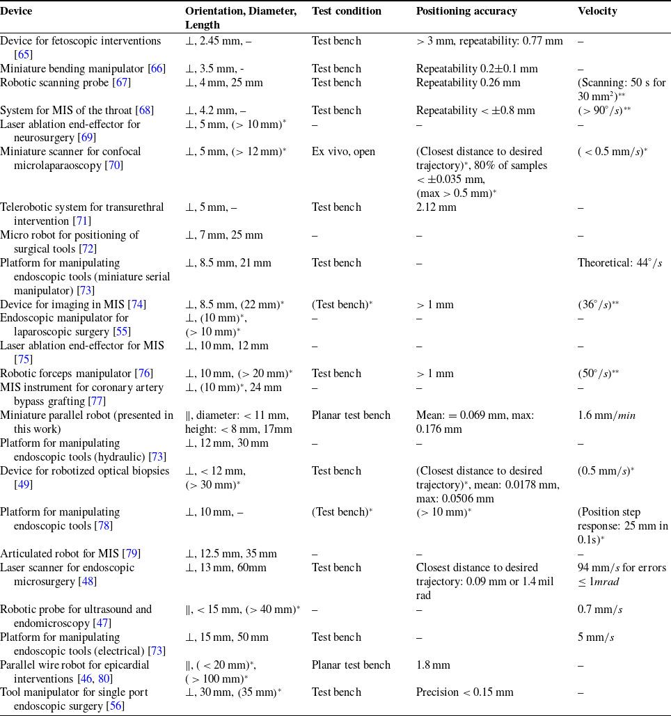
(…)*: estimated based on paper content.
(…)**: accuracy and velocity have been determined independent of each other.
B. Kinematics
B.1 Direct kinematics
The direct kinematic calculations based on the distance between the left anchor point and the end effector position yields
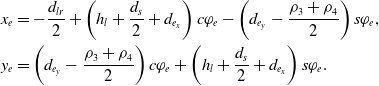 \begin{equation}\begin{aligned}x_e &= -\frac{d_{lr}}{2}+\left(h_l+\frac{d_s}{2}+d_{e_x}\right) c\varphi_e- \left(d_{e_y}-\frac{\rho_3+\rho_4}{2} \right) s\varphi_e, \\y_e &= \left( d_{e_y}-\frac{\rho_3+\rho_4}{2} \right) c\varphi_e +\left(h_l+\frac{d_s}{2}+d_{e_x}\right) s\varphi_e.\end{aligned}\end{equation}
B.2 Inverse kinematics
To calculate the inverse kinematics, we rearrange the direct kinematic equations given in (10) to obtain
 \begin{align}x_e &= -h_r c\varphi_e + \frac{\rho_1+\rho_2}{2} s{\varphi_e} + b_1, \end{align}
 \begin{align}y_e &= -h_r s\varphi_e - \frac{\rho_1+\rho_2}{2} c{\varphi_e} + b_2, \end{align}
where the values of $b_1$
and
$b_1$
and $b_2$
are
$b_2$
are
 \begin{align}b_1 = \frac{d_{lr}}{2}-d_{e_y} s\varphi_e-\left(\frac{d_{s}}{2}-d_{e_x}\right) c\varphi_e, \quad b_2 = d_{e_y} c\varphi_e-\left(\frac{d_{s}}{2}-d_{e_x}\right) s\varphi_e.\end{align}
Combining (B2) and (B3), we obtain
 \begin{align}\frac{\rho_1+\rho_2}{2} &= x_e s\varphi_e -y_e c\varphi_e - b_1 s\varphi_e + b_2 c\varphi_e, \end{align}
 \begin{align}h_r &= -x_e c\varphi_e - y_e s\varphi_e + b_1 c\varphi_e + b_2 s\varphi_e. \end{align}
We then combine (B6) with (9), yielding
 \begin{equation}\begin{aligned}\pm \frac{\rho_2-\rho_1}{2} &= \sqrt{d_a^2-w_1^2}, \\w_1^2 &= (-x_e c\varphi_e - y_e s\varphi_e + b_1 c\varphi_e + b_2 s\varphi_e)^2.\end{aligned}\end{equation}
Using (B7) and (9) we obtain equations for $\rho_1$
and
$\rho_1$
and $\rho_2$
. Applying the same procedure to the equations given in (B1) leads to results for
$\rho_2$
. Applying the same procedure to the equations given in (B1) leads to results for $\rho_3$
and
$\rho_3$
and $\rho_4$
.
$\rho_4$
.


 Open access

