


1. Introduction
In the realm of mechatronic systems, parallel manipulators (PMs) have gained significant attention due to their inherent advantages such as high stiffness, high precision, high load-to-weight ratio, and highly responsive capabilities due to their parallel leg configuration, where the moving platform is connected to the base by multiple parallel legs. The attractive features of PMs make them well suited for a wide range of applications in various industries. A prime example of this is the Stewart platform, a 6-degree-of-freedom (DoF) mechanism comprised of two bodies connected by six extensible legs [Reference Stewart1]. In addition to traditional applications such as automotive, testing, and simulation, PMs are utilized in various advanced fields including robotic-assisted surgery, virtual and augmented reality, arc welding, haptic operations, inspection and surveillance, wave compensation, UAV stabilization, and precision assembly as given by [Reference Bertelsen, Melo, Sánchez and Borro2–Reference Herbuś and Ociepka5].
With growing interest in PMs across industry and academia, their potential has become increasingly apparent. However, realizing this potential requires overcoming several challenges related to the inherent complex kinematic structures, nonlinear dynamics, coupled actuation and redundancy, significant flexibility, backlash, and friction [Reference Müller6–Reference Merlet9]. Consequently, the mathematical representation of a robot typically serves as an approximation of the actual system, leading to unavoidable modeling inaccuracies. Therefore, there is a demand for control approaches characterized by robustness, adaptability, rapid convergence, and simplicity of structure.
Due to its straightforward design and widespread adoption among engineers, PD/PID controls have found extensive use in various industrial domains, including PM robotic applications [Reference Spong, Hutchinson and Vidyasagar10–Reference Pervozvanski and Freidovich12]. In order to obtain asymptotic stability, some feedforward terms are also added to PD/PID terms [Reference Craig13–Reference Cervantes and Alvarez-Ramirez14]. Such simple techniques may be appropriate for relatively slow systems with moderate tracking performance. To fully leverage their dynamic capabilities and achieve desired tracking accuracy, sophisticated control schemes are also proposed in the literature. Adaptive control approaches for PMs are proposed in [Reference Bennehar15–Reference Harandi, Khalilpour, Taghirad and Romero17]. Sliding mode control (SMC) has emerged as a highly developed advanced control technique within the field of robotics. Robust variable structure controllers utilizing SMC are inherently appealing in the realm of PMs due to their ability to handle uncertainties effectively, provide excellent transient performance with minimal tracking error, and deliver rapid responses. To address the limitations associated with SMC – notably chattering and the requirement for prior knowledge of perturbation bounds – researchers have proposed several advanced methods and modifications to the traditional SMC approach [Reference Utkin, Guldner and Shi18–Reference Dumlu and Erenturk21]. Reinforcement learning, artificial neural networks, and fuzzy control methods have been proposed as intelligent control techniques for PMs [Reference Yadavari, Aghaei and İkizoğlu22–Reference Li and Gao25]. In addition, various control techniques have been suggested such as model predictive control, disturbance rejection control, computed torque control, observer-based control, H-infinity control, and passivity-based control for PM [Reference Natal, Chemori and Pierrot26–Reference Rachedi and Bouri29]. Nevertheless, individual control methods often struggle to address the diverse complexities of PMs. In recent years, hybrid control fusion techniques have emerged as an effective solution to overcome these challenges. Some examples of hybrid control combinations include SMC with PD control, computed torque control with PD, and SMC with adaptive observer [Reference Coutinho and Hess-Coelho30–Reference Kara and Mary32]. However, most studies have been validated solely by computer simulations.
In the realm of PMs, control strategies fall primarily into two categories: joint-space control and task-space control. Joint-space control offers a simpler approach, treating each leg of the manipulator as an independent system. This method is prevalent in industrial settings and utilizes basic controllers for individual legs. However, neglecting the dynamic interactions between legs (coupling effects) can lead to synchronization issues and low tracking performance [Reference Shiferaw and Jain33]. In contrast, task-space control prioritizes superior performance by accounting for coupling between the manipulator’s legs. This necessitates more complex control algorithms due to the multiple-input/multiple-output nature of the system. While offering better performance, task-space control relies on real-time position and velocity measurements, often requiring expensive sensors, limiting its practicality in certain situations [Reference Kumar, Chalanga and Bandyopadhyay34].
This paper introduces two novel control systems for PMs. The first control system is based on a hybrid control approach within the joint space, merging acceleration-based control (AbC) with sliding mode and disturbance observer (DOB) techniques. The objective is to achieve high-precision position tracking while effectively managing external disturbances and model uncertainties. The AbC method likely focuses on the dynamic aspects of the system, using acceleration commands to drive the system toward the desired state. The SMC part enhances the robustness of the controller against uncertainties inherent in the system model, and the DOB actively compensates for external disturbances that may affect the manipulator’s tracking performances.
The second control system is based on combined joint-space and task-space formulations, which simultaneously address control in both joint and task spaces. In task space, a PD controller is designed to regulate the end-effector positions. This integrated control approach aims to improve precision not only in individual joint movements but also in achieving the desired end-effector positions and orientations. In addition, the control algorithm can be designed to prioritize configurations that maintain a safe and stable operational space, minimizing the risk of encountering singularities during manipulator movements.
The paper is structured as follows. Section 2 provides an overview of the mathematical foundations of PMs. In Section 3, the design of the proposed control techniques and their stability analysis are discussed. Section 4 presents the simulation results obtained from the implementation of the proposed control techniques. This is followed by Section 5, which describes the experimental verification of the control techniques. Finally, Section 6 presents the conclusions drawn from the study.
2. Mathematical modeling
2.1. Kinematics
2.1.1. Inverse kinematics
In this study, simulation and experimentation are conducted on a 6-DoF PM. It consists of a fixed base (lower) and a moving (upper or end-effector) platform (frames) connected by six extendable legs. The legs are connected to the fixed base via spherical or universal joints and to the moving platform via universal joints. 6-DoF robot involves linear position and orientations as represented in Figure 1. Linear motions encompass movements along the longitudinal (surge), lateral (sway), and vertical (heave) axes. Angular movements, on the other hand, are described by rotations about x- (roll), y- (pitch), and z-axes (yaw), respectively. The inverse kinematics problem of PM robot focuses on determining the required leg lengths corresponding to a desired position and orientation of the moving platform, which is essential for control of moving platform and ensuring the robot’s ability to achieve complex tasks with required accuracy.
Kinematic configurations of the 6-DoF parallel manipulator.
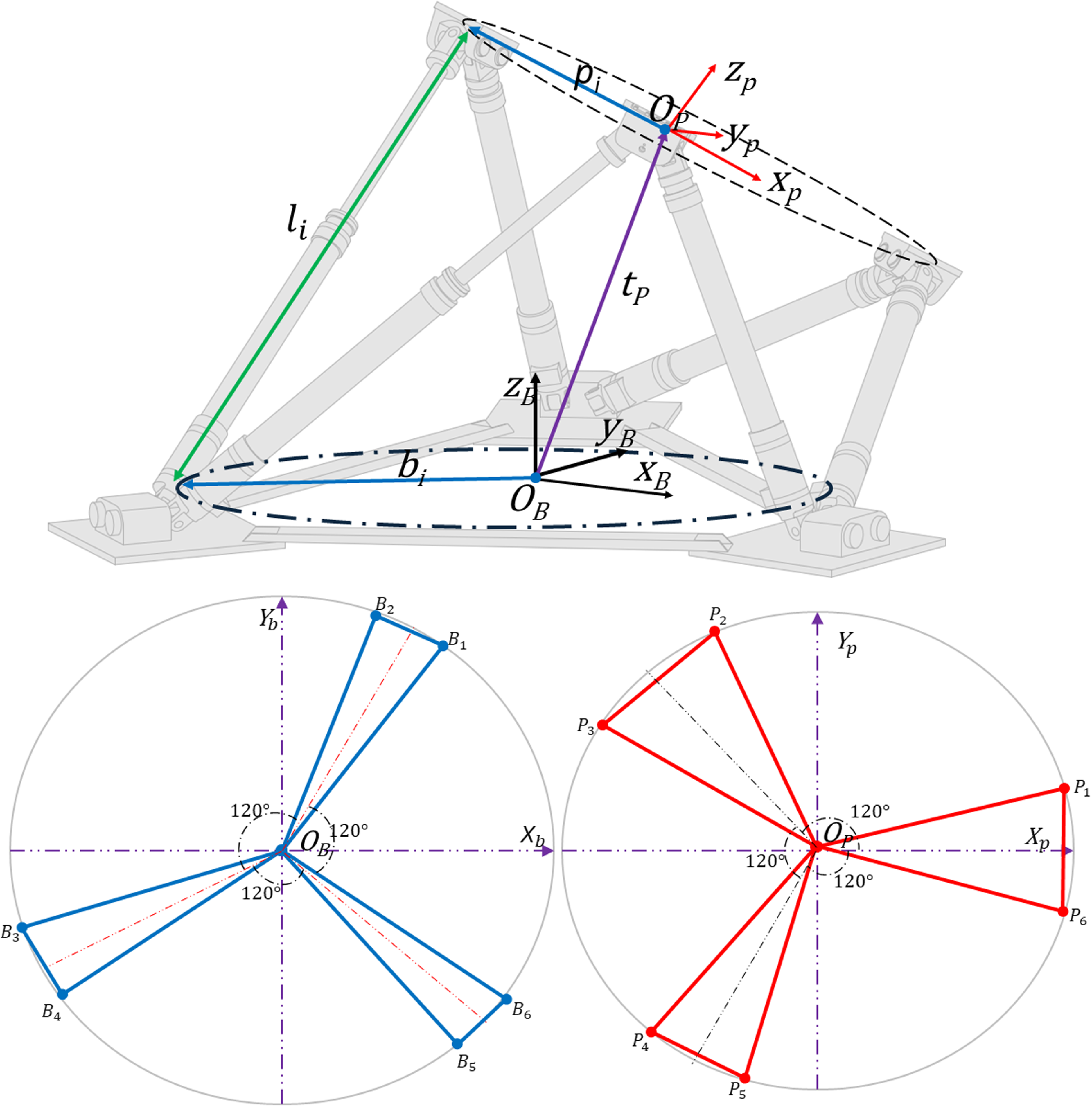
To derive the equations of inverse kinematics, we establish two reference frames, $B$
and
$B$
and $P$
, fixed to the base and moving platform, respectively, with origins
$P$
, fixed to the base and moving platform, respectively, with origins $O_B$
and
$O_B$
and $O_P$
. The connection points of the lower and upper plate joints are designated as
$O_P$
. The connection points of the lower and upper plate joints are designated as $B_i$
and
$B_i$
and $P_i$
, respectively, where
$P_i$
, respectively, where $i=1,\ldots, 6$
. The angles between
$i=1,\ldots, 6$
. The angles between $B_1$
to
$B_1$
to $B_2$
and
$B_2$
and $B_3$
to
$B_3$
to $B_5$
are set to
$B_5$
are set to $120^\circ$
to symmetrically distribute connection points on the base plate, a symmetry also maintained for the upper platform. The angles between adjacent joints on the upper platform are denoted as
$120^\circ$
to symmetrically distribute connection points on the base plate, a symmetry also maintained for the upper platform. The angles between adjacent joints on the upper platform are denoted as $\theta _P$
, while those on the lower platform are denoted as
$\theta _P$
, while those on the lower platform are denoted as $\theta _B$
as shown in Figure 1. The position vectors of the centers of spherical joints in frame
$\theta _B$
as shown in Figure 1. The position vectors of the centers of spherical joints in frame $P$
are denoted by
$P$
are denoted by $ \mathbf {P}_i$
and can be expressed as follows:
$ \mathbf {P}_i$
and can be expressed as follows:
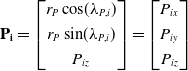 \begin{align} \mathbf {P_i} = \begin{bmatrix} r_P \cos\!(\lambda _{P,i}) \\[3pt] r_P \sin\!(\lambda _{P,i}) \\[3pt] P_{iz} \end{bmatrix} = \begin{bmatrix} P_{ix} \\[3pt] P_{iy} \\[3pt] P_{iz} \end{bmatrix} \end{align}
where $\lambda _P$
is the upper frame joints’ position angles relative to the moving frame
$\lambda _P$
is the upper frame joints’ position angles relative to the moving frame $O_P$
axis and
$O_P$
axis and $r_P$
is the radius of the moving platform passing through the connecting points.
$r_P$
is the radius of the moving platform passing through the connecting points.
Similarly, the position vectors of the centers of spherical joints in frame $B$
are denoted by
$B$
are denoted by $ \mathbf {B}_i$
and can be expressed as follows:
$ \mathbf {B}_i$
and can be expressed as follows:
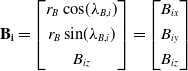 \begin{align} \mathbf {B_i} = \begin{bmatrix} r_B \cos\!(\lambda _{B,i}) \\[3pt] r_B \sin\!(\lambda _{B,i}) \\[3pt] B_{iz} \end{bmatrix} = \begin{bmatrix} B_{ix} \\[3pt] B_{iy} \\[3pt] B_{iz} \end{bmatrix} \end{align}
where $\lambda _B$
is the lower frame joints’ position angles relative to the fixed frame
$\lambda _B$
is the lower frame joints’ position angles relative to the fixed frame $O_B$
axis and
$O_B$
axis and $r_B$
is the radius of the fixed platform passing through the connecting points.
$r_B$
is the radius of the fixed platform passing through the connecting points.
The 6-DoF of the upper frame including three translations and three rotations are defined within the following vector:
 \begin{align} \mathbf {X} = \begin{bmatrix} x & \quad y & \quad z & \quad \alpha & \quad \beta & \gamma \end{bmatrix}^T \end{align}
In this context, $ x$
,
$ x$
, $ y$
, and
$ y$
, and $ z$
denote surge, sway, and heave translations, respectively, and
$ z$
denote surge, sway, and heave translations, respectively, and $ \alpha$
,
$ \alpha$
, $ \beta$
, and
$ \beta$
, and $ \gamma$
represent roll, pitch, and yaw rotations of the moving platform relative to the fixed frame
$ \gamma$
represent roll, pitch, and yaw rotations of the moving platform relative to the fixed frame $O_B$
. The inverse kinematics of a PM typically provide a unique solution. Specifically, when the position and orientation of the upper platform are specified, the lengths of the legs corresponding to these configurations can be precisely determined using the inverse kinematics model. This method employs closed-loop vectors based on geometric relationships and trigonometry within the system. Subsequently, the leg vector pointing from attachment point
$O_B$
. The inverse kinematics of a PM typically provide a unique solution. Specifically, when the position and orientation of the upper platform are specified, the lengths of the legs corresponding to these configurations can be precisely determined using the inverse kinematics model. This method employs closed-loop vectors based on geometric relationships and trigonometry within the system. Subsequently, the leg vector pointing from attachment point $ B_i$
to attachment point
$ B_i$
to attachment point $ P_i$
can be expressed as follows:
$ P_i$
can be expressed as follows:
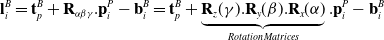 \begin{align} \mathbf {l}_{i}^B = \mathbf t_{p}^B + \mathbf R_{\alpha \beta \gamma }.\mathbf p_{i}^P - \mathbf b_{i}^B = \mathbf t_{p}^B + \underbrace {\mathbf R_{z}(\gamma ) . \mathbf R_{y}(\beta ) . \mathbf R_{x}(\alpha )}_{Rotation\,Matrices} . \mathbf p_{i}^P - \mathbf b_{i}^B \end{align}
where $\mathbf t_{p}^B = \begin{bmatrix} p_x & p_y & p_z \end{bmatrix}^T$
is the moving platform translation vector, with respect to the base origin
$\mathbf t_{p}^B = \begin{bmatrix} p_x & p_y & p_z \end{bmatrix}^T$
is the moving platform translation vector, with respect to the base origin $O_B$
, and
$O_B$
, and $\mathbf p_{i}^P = \begin{bmatrix} P_{ix} & P_{iy} & P_{iz} \end{bmatrix}^T$
and
$\mathbf p_{i}^P = \begin{bmatrix} P_{ix} & P_{iy} & P_{iz} \end{bmatrix}^T$
and $\mathbf b_{i}^B = \begin{bmatrix} B_{ix} & B_{iy} & B_{iz} \end{bmatrix}^T$
are the translational offset vectors of the
$\mathbf b_{i}^B = \begin{bmatrix} B_{ix} & B_{iy} & B_{iz} \end{bmatrix}^T$
are the translational offset vectors of the $i^{th}$
leg on the moving and base platforms, respectively. The matrix
$i^{th}$
leg on the moving and base platforms, respectively. The matrix $R_{\alpha \beta \gamma }$
representing the orientation of the frame
$R_{\alpha \beta \gamma }$
representing the orientation of the frame $P$
with respect to frame
$P$
with respect to frame $B$
is expressed as follows:
$B$
is expressed as follows:
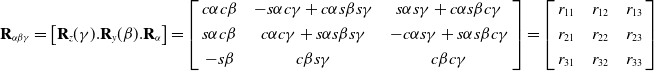 \begin{align} \mathbf R_{\alpha \beta \gamma } = \begin{bmatrix} \mathbf R_{z}(\gamma ) . \mathbf R_{y}(\beta ) . \mathbf R_{\alpha }\end{bmatrix} = \left[\begin{array}{c@{\quad}c@{\quad}c} c\alpha c\beta & -s\alpha c\gamma + c\alpha s\beta s\gamma & s\alpha s\gamma + c\alpha s\beta c\gamma \\[3pt] s\alpha c\beta & c\alpha c\gamma + s\alpha s\beta s\gamma & -c\alpha s\gamma + s\alpha s\beta c\gamma \\[3pt] -s\beta & c\beta s\gamma & c\beta c\gamma \end{array}\right] = \left[\begin{array}{c@{\quad}c@{\quad}c} r_{11} & r_{12} & r_{13} \\[3pt] r_{21} & r_{22} & r_{23} \\[3pt] r_{31} & r_{32} & r_{33} \end{array}\right] \end{align}
where $c$
and
$c$
and $s$
denote, respectively
$s$
denote, respectively $cos(.)$
and
$cos(.)$
and $sin(.)$
. From Eq. (4), the length of the
$sin(.)$
. From Eq. (4), the length of the $i^{th}$
leg can be calculated by
$i^{th}$
leg can be calculated by $||l_{i}||$
, which solves the six leg lengths of the PM robot. Hence the complete solution for the inverse kinematics can be expressed as follows:
$||l_{i}||$
, which solves the six leg lengths of the PM robot. Hence the complete solution for the inverse kinematics can be expressed as follows:
 \begin{align} ||l_{i}|| = \sqrt {\begin{bmatrix} (t_{p}^B + R_{pqr}.p_{i}^P - b_{i}^B)^T & (t_{p}^B + R_{\alpha \beta \gamma }.p_{i}^P - b_{i}^B) \end{bmatrix}} \end{align}
for i = 1, 2, …, 6
2.1.2. Kinematic Jacobian
For parallel robots, the direct kinematic problem (finding the end-effector position given the joint positions) is often difficult to solve due to their closed-loop structure. Therefore, the inverse kinematic problem (finding the joint positions given the end-effector position) is typically solved first. Once the inverse kinematics are known, the inverse kinematic Jacobian can be derived. It’s used to connect joint velocities and forces to the end-effector velocities, torque, and forces. Moreover, the characteristics of the Jacobian are frequently employed in examining kinematic singularities. The leg positions being functions of end-effector positions are defined as follows:
 \begin{align} l_i = f_i(x,y,z,\alpha, \beta, \gamma ) = f_i(\mathbf X) \quad \text {for} \quad i = 1, 2, \ldots, 6 \end{align}
The leg velocities, in terms of the upper platform velocities, are obtained by applying the chain rule to the partial derivatives of the functions $f_i$
. This results in the derivatives of
$f_i$
. This results in the derivatives of $l_i$
being expressed as functions of the derivatives of
$l_i$
being expressed as functions of the derivatives of $x$
,
$x$
, $y$
, z,
$y$
, z, $\alpha$
,
$\alpha$
, $\beta$
,
$\beta$
, $\gamma$
.
$\gamma$
.
 \begin{align} \delta l_i = \frac {\partial f_i}{\partial x} \delta x + \frac {\partial f_i}{\partial y} \delta y + \frac {\partial f_i}{\partial z} \delta z + \frac {\partial f_i}{\partial \alpha } \delta \alpha + \frac {\partial f_i}{\partial \beta } \delta \beta + \frac {\partial f_i}{\partial \gamma } \delta \gamma \end{align}
Dividing both sides by the differential time element $ \delta t$
and arranging in matrix form yields:
$ \delta t$
and arranging in matrix form yields:
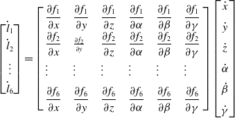 \begin{align} \begin{bmatrix} \dot {l}_1 \\[3pt] \dot {l}_2 \\[3pt] \vdots \\[3pt] \dot {l}_6 \end{bmatrix} = \left[\begin{array}{l@{\quad}l@{\quad}l@{\quad}l@{\quad}l@{\quad}l} \dfrac {\partial f_1}{\partial x} & \dfrac {\partial f_1}{\partial y} & \dfrac {\partial f_1}{\partial z} & \dfrac {\partial f_1}{\partial \alpha } & \dfrac {\partial f_1}{\partial \beta } & \dfrac {\partial f_1}{\partial \gamma } \\[6pt] \dfrac {\partial f_2}{\partial x} & \frac {\partial f_2}{\partial y} & \dfrac {\partial f_2}{\partial z} & \dfrac {\partial f_2}{\partial \alpha } & \dfrac {\partial f_2}{\partial \beta } & \dfrac {\partial f_2}{\partial \gamma } \\[6pt] \vdots & \vdots & \vdots & \vdots & \vdots & \vdots \\[6pt] \dfrac {\partial f_6}{\partial x} & \dfrac {\partial f_6}{\partial y} & \dfrac {\partial f_6}{\partial z} & \dfrac {\partial f_6}{\partial \alpha } & \dfrac {\partial f_6}{\partial \beta } & \dfrac {\partial f_6}{\partial \gamma } \end{array}\right] \begin{bmatrix} \dot {x} \\[6pt]\dot {y} \\[6pt] \dot {z} \\[6pt]\dot {\alpha } \\[6pt] \dot {\beta } \\[6pt] \dot {\gamma } \end{bmatrix} \end{align}
Let $ J^{-1} \in \mathbb {R}^{6 \times 6}$
denote the inverse Jacobian (kinematic Jacobian) matrix composed of these partial derivatives. The forward and inverse kinematics are then expressed as follows:
$ J^{-1} \in \mathbb {R}^{6 \times 6}$
denote the inverse Jacobian (kinematic Jacobian) matrix composed of these partial derivatives. The forward and inverse kinematics are then expressed as follows:
 \begin{align} \dot {\mathbf {X}} = J \dot {\mathbf {l}} \\[-24pt] \nonumber \end{align}
 \begin{align} \dot {\mathbf {l}} = J^{-1} \dot {\mathbf {X}} \end{align}
Here, $ \mathbf {X} \in \mathbb {R}^6$
represents the task-space end-effector positions, while
$ \mathbf {X} \in \mathbb {R}^6$
represents the task-space end-effector positions, while $ \dot {\mathbf {X}}$
and
$ \dot {\mathbf {X}}$
and $ \ddot {\mathbf {X}}$
are the corresponding velocities and accelerations.
$ \ddot {\mathbf {X}}$
are the corresponding velocities and accelerations. $ J \in \mathbb {R}^{6 \times 6}$
is the Jacobian matrix.
$ J \in \mathbb {R}^{6 \times 6}$
is the Jacobian matrix.
2.1.3. Forward kinematics
The forward kinematics determines the position and orientation of the upper platform based on the provided leg lengths. The forward kinematics of a PM involve a set of complex nonlinear differential equations, making them challenging to solve. As a result, iterative solvers such as the Newton–Raphson method are commonly used to obtain approximate solutions. The general form of the function used for forward kinematics can be given as follows:
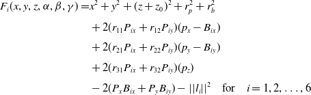 \begin{align} \begin{split} F_i(x,y,z,\alpha, \beta, \gamma ) = & x^2 + y^2 + (z+z_0)^2 + r_p^2 + r_b^2 \\[3pt] & + 2(r_{11} P_{ix} + r_{12} P_{iy})(p_x - B_{ix}) \\[3pt] & + 2(r_{21} P_{ix} + r_{22} P_{iy})(p_y - B_{iy}) \\[3pt] & + 2(r_{31} P_{ix} + r_{32} P_{iy})(p_z) \\[3pt] & - 2(P_x B_{ix} + P_y B_{iy})-||l_{i}||^2 \quad \text {for} \quad i = 1, 2, \ldots, 6 \end{split} \end{align}
2.2. Dynamics
The dynamic modeling of PMs presents significant complexity and nonlinearity due to the constraints within their closed-loop structure. Multiple kinematic chains connect the moving platform to the fixed base, causing the motion of a single joint to directly influence several others, resulting in a high degree of coupling. These closed loops also impose nonlinear geometric constraints on the system’s motion. To manage this complexity, the dynamic model is typically expressed in a general and compact form. The dynamics of the robot manipulator, considering uncertainties and disturbances, are described as follows:
 \begin{align} M(\mathbf q)\ddot {\mathbf q} + V(\mathbf q, \dot {\mathbf q})\dot {\mathbf q} + G(\mathbf q) + F(\dot {\mathbf q}) = \boldsymbol {\tau } (t) - \mathbf d(t) \end{align}
where $\mathbf q(t) := [q_1(t), q_2(t), \ldots, q_n(t)]^T \in \mathbb {R}^n$
denotes the joint positions,
$\mathbf q(t) := [q_1(t), q_2(t), \ldots, q_n(t)]^T \in \mathbb {R}^n$
denotes the joint positions, $\dot {\mathbf {q}}(t) \in \mathbb {R}^n$
the joint velocities, and
$\dot {\mathbf {q}}(t) \in \mathbb {R}^n$
the joint velocities, and $\ddot {\mathbf {q}}(t) \in \mathbb {R}^n$
the joint accelerations.
$\ddot {\mathbf {q}}(t) \in \mathbb {R}^n$
the joint accelerations. $M(\mathbf q) \in \mathbb {R}^{n \times n}$
,
$M(\mathbf q) \in \mathbb {R}^{n \times n}$
, $V(\mathbf q, {\dot{\mathbf{q}}}) \in \mathbb {R}^{n \times n}$
,
$V(\mathbf q, {\dot{\mathbf{q}}}) \in \mathbb {R}^{n \times n}$
, $G(\mathbf q) \in \mathbb {R}^n$
, and
$G(\mathbf q) \in \mathbb {R}^n$
, and $F( {\dot{\mathbf{q}}}) \in \mathbb {R}^n$
are the inertia matrix, centripetal-Coriolis matrix, gravitational torque, and friction torque, respectively.
$F( {\dot{\mathbf{q}}}) \in \mathbb {R}^n$
are the inertia matrix, centripetal-Coriolis matrix, gravitational torque, and friction torque, respectively. $\mathbf d(t) \in \mathbb {R}^n$
and
$\mathbf d(t) \in \mathbb {R}^n$
and $\mathbf {\tau }(t) \in \mathbb {R}^n$
denote the external disturbances and input force, respectively.
$\mathbf {\tau }(t) \in \mathbb {R}^n$
denote the external disturbances and input force, respectively.
Based on [Reference Spong, Hutchinson and Vidyasagar10], the dynamic model satisfies the following properties:
Property 1. The inertia matrix $M(\mathbf q)$
is symmetric positive definite and satisfies
$M(\mathbf q)$
is symmetric positive definite and satisfies $M(\mathbf q) = M^T(\mathbf q) \gt 0$
, where
$M(\mathbf q) = M^T(\mathbf q) \gt 0$
, where $m_1 \|x\|^2 \leq x^T M(q) x \leq m_2 \|x\|^2$
for all
$m_1 \|x\|^2 \leq x^T M(q) x \leq m_2 \|x\|^2$
for all $x \in \mathbb {R}^n$
.
$x \in \mathbb {R}^n$
.
Property 2. $\dot {M}(\mathbf q)$
is bounded.
$\dot {M}(\mathbf q)$
is bounded.
Property 3. $\dot {M}(\mathbf q)$
is skew-symmetric and satisfies
$\dot {M}(\mathbf q)$
is skew-symmetric and satisfies $x^T (\dot {M}(\mathbf q) - 2V(\mathbf q, \dot {\mathbf {q}})) x = 0$
for all
$x^T (\dot {M}(\mathbf q) - 2V(\mathbf q, \dot {\mathbf {q}})) x = 0$
for all $x \in \mathbb {R}^n$
.
$x \in \mathbb {R}^n$
.
Property 4. The friction torque $F(\dot {\mathbf {q}})$
is uncoupled among joints and expressed as
$F(\dot {\mathbf {q}})$
is uncoupled among joints and expressed as $F(\dot {\mathbf {q}}) = [f_1(\dot {q}_1), f_2(\dot {q}_2), \ldots, f_n(\dot {q}_n)]^T$
, where
$F(\dot {\mathbf {q}}) = [f_1(\dot {q}_1), f_2(\dot {q}_2), \ldots, f_n(\dot {q}_n)]^T$
, where $f_i(\dot {q}_i)$
is bounded and continuous.
$f_i(\dot {q}_i)$
is bounded and continuous.
Property 5. The trajectory of joints positions, velocities, and accelerations $\mathbf q(t)$
,
$\mathbf q(t)$
, $\dot {\mathbf {q}}(t)$
, and
$\dot {\mathbf {q}}(t)$
, and $\ddot {\mathbf {q}}(t)$
exist and are bounded.
$\ddot {\mathbf {q}}(t)$
exist and are bounded.
The system is subject to uncertainties stemming from factors such as inertia loading, unmodeled dynamics, and friction from the actuators and transmissions. These uncertainties are expected to be bounded and can be represented in the dynamic model as follows:
 \begin{align} (M_n(\mathbf {q}) + \Delta M(\mathbf {q}))\ddot {\mathbf {q}} + (C(\mathbf {q}, \dot {\mathbf {q}})+ \Delta C(\mathbf {q}, \dot {\mathbf {q}}))\dot {\mathbf {q}} + G(\mathbf {q})+ \Delta G(\mathbf {q}) + F(\dot {\mathbf {q}}) = \boldsymbol {\tau }(t) - \mathbf {d}(t) \end{align}
where $\Delta$
represents deviations from the nominal parameters.
$\Delta$
represents deviations from the nominal parameters.
The dynamic model can be rewritten in the following compact form:
 \begin{align} M_n(\mathbf {q})\ddot {\mathbf {q}} + V_n(\mathbf {q}, \dot {\mathbf {q}})\dot {\mathbf {q}} + G_n(\mathbf {q}) = \tau (t) - \boldsymbol {\tau }_{\text {dis}}(t, \mathbf {q}) \end{align}
where $\boldsymbol {\tau _{\text {dis}}}(t, \mathbf q)$
is the lumped disturbance vector defined as follows:
$\boldsymbol {\tau _{\text {dis}}}(t, \mathbf q)$
is the lumped disturbance vector defined as follows:
 \begin{align} \boldsymbol {\tau }_{\text {dis}}(t, \mathbf {q}) = -\Delta M \ddot {\mathbf {q}} - \Delta V \dot {\mathbf {q}} - \Delta G - F(\dot {\mathbf {q}}) - \mathbf {d}(t) \end{align} $\Delta M$
,
$\Delta M$
, $\Delta V$
, and
$\Delta V$
, and $\Delta G$
represent the corresponding modeling errors and are assumed to be bounded. The terms
$\Delta G$
represent the corresponding modeling errors and are assumed to be bounded. The terms $M_n$
,
$M_n$
, $V_n$
and
$V_n$
and $G_n$
represent the nominal dynamic model components.
$G_n$
represent the nominal dynamic model components.
3. Control system design
3.1. Hybrid control in joint space
3.1.1. Description of the controller
AbC or acceleration control (ACC) is a control strategy that directly employs joint accelerations to command robotic manipulators. By utilizing feedforward acceleration reference, AbC can potentially achieve faster behavior and more accurate tracking performance compared to traditional control methods. However, disturbances such as external forces, friction, or modeling errors can affect the system’s performance. To mitigate the effects of disturbances, a DOB is integrated into the AbC architecture as described in ref. [Reference Sariyildiz, Oboe and Ohnishi40]. While the AbC with DOB offers improved tracking performance and disturbance rejection, it may still struggle with highly nonlinear systems and random disturbances. In this study, a sliding mode controller is introduced alongside the AbC with DOB, constituting a hybrid controller. This hybridization allows the system to leverage the strengths of each individual method while compensating for their respective weaknesses. Let us define the joint position errors $\mathbf {e} \in \mathbb {R}^6$
of the joints as follows:
$\mathbf {e} \in \mathbb {R}^6$
of the joints as follows:
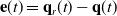 \begin{align} \mathbf e(t) = \mathbf q_r(t) - \mathbf q(t) \end{align}
where $\mathbf q_r \in \mathbb {R}^6$
is the vector of reference actuators (joints) trajectories. Let us define the sliding surface as follows:
$\mathbf q_r \in \mathbb {R}^6$
is the vector of reference actuators (joints) trajectories. Let us define the sliding surface as follows:
 \begin{align} \mathbf {s}(t) = \dot {\mathbf {q}}_r(t) - \dot {\mathbf {q}}(t) + \lambda (\mathbf {q}_r(t) - \mathbf {q}(t)) = \dot {\mathbf {e}}(t) + \lambda \mathbf {e}(t) \end{align}
where $ \mathbf {s}(t) \in \mathbb {R}^6$
represents the sliding surface,
$ \mathbf {s}(t) \in \mathbb {R}^6$
represents the sliding surface, $\dot {\mathbf {e}}(t) \in \mathbb {R}^6$
is the joint tracking rate error, and
$\dot {\mathbf {e}}(t) \in \mathbb {R}^6$
is the joint tracking rate error, and $\dot {\mathbf {q}}_r(t) \in \mathbb {R}^6$
is the vector of desired velocities.
$\dot {\mathbf {q}}_r(t) \in \mathbb {R}^6$
is the vector of desired velocities. $\lambda = \text {diag}(\lambda )$
with
$\lambda = \text {diag}(\lambda )$
with $\lambda \gt 0$
for
$\lambda \gt 0$
for $(i = 1,\ldots, 6)$
is the diagonal positive definite constant matrix that determines the slope of the sliding surface.
$(i = 1,\ldots, 6)$
is the diagonal positive definite constant matrix that determines the slope of the sliding surface.
The time derivative of the sliding surface is then given as follows:
 \begin{align} \dot {\mathbf {s}}(t) = \ddot {\mathbf {q}}_r(t) - \ddot {\mathbf {q}}(t) + \lambda (\dot {\mathbf {q}}_r(t) - \dot {\mathbf {q}}(t)) = \ddot {\mathbf {e}}(t) + \lambda \dot {\mathbf {e}}(t) \end{align}
Based on Eq. (15), the expression of the acceleration vector is written as follows:
 \begin{align} \ddot {\mathbf {q}}(t) = {M}_n^{-1}(\mathbf {q}) (\tau (t) - \boldsymbol {\tau _{\text {dis}}}(t, \mathbf {q}) - V_n(\mathbf {q}, \dot {\mathbf {q}})\dot {\mathbf {q}} - G_n(\mathbf {q})) \end{align}
Inserting Eq. (19) into Eq. (18), one gets
 \begin{align} \dot {\mathbf {s}}(t) = \ddot {\mathbf {q}}_r(t) - {M}_n^{-1}(\mathbf {q}) \left (\tau (t) - \boldsymbol {\tau _{\text {dis}}}(t, \mathbf q) - V_n(\mathbf {q}, \dot {\mathbf {q}})\dot {\mathbf {q}} - G_n(\mathbf {q})\right ) + \lambda \dot {\mathbf {e}}(t) \end{align}
The system dynamics are designed to reach the sliding surface in a finite time. A common reaching law could be as follows:
 \begin{align} \dot {\mathbf s}(t) = -k_0 \text {sgn} (\mathbf s(t)) - \eta \mathbf s(t) \end{align}
where $ k_0$
and
$ k_0$
and $ \eta$
are positive constants and
$ \eta$
are positive constants and $ \text {sgn} (\mathbf s(t))$
denotes the signum function. Based on Eq. (21) and Eq. (22), the input force or control law can be obtained as follows:
$ \text {sgn} (\mathbf s(t))$
denotes the signum function. Based on Eq. (21) and Eq. (22), the input force or control law can be obtained as follows:
 \begin{align} \boldsymbol {\tau }(t) = M_n(\mathbf {q}) (\ddot {\mathbf {q}}_r(t) + k_0 \text {sgn}(\mathbf {s}(t)) + \eta \mathbf {s}(t) + \lambda \dot {\mathbf {e}}(t)) + \boldsymbol {\tau }_{\text {dis}}(t, \mathbf {q}) + V_n(\mathbf {q}, \dot {\mathbf {q}})\dot {\mathbf {q}} + G_n(\mathbf {q})) \end{align}
Here $\boldsymbol {\tau }(t)$
is control law, but
$\boldsymbol {\tau }(t)$
is control law, but $\boldsymbol \tau _{\text {dis}}(t, q)$
contains modeling mismatch, friction, and other disturbances. In order to address these generalized disturbances, an appropriate estimation law
$\boldsymbol \tau _{\text {dis}}(t, q)$
contains modeling mismatch, friction, and other disturbances. In order to address these generalized disturbances, an appropriate estimation law $\boldsymbol {\tau _{\text {dob}}} (t, q)$
, which is the estimated output of
$\boldsymbol {\tau _{\text {dob}}} (t, q)$
, which is the estimated output of $\boldsymbol {\tau _{\text {dis}}}(t, q)$
, will be incorporated into the control law. Based on [Reference Sariyildiz, Oboe and Ohnishi40–Reference Mohammadi, Tavakoli, Marquez and Hashemzadeh42], the estimation of the disturbance vector can be derived in terms of an auxiliary variable and the states of the system by utilizing the known nonlinear dynamic model of PMs as follows:
$\boldsymbol {\tau _{\text {dis}}}(t, q)$
, will be incorporated into the control law. Based on [Reference Sariyildiz, Oboe and Ohnishi40–Reference Mohammadi, Tavakoli, Marquez and Hashemzadeh42], the estimation of the disturbance vector can be derived in terms of an auxiliary variable and the states of the system by utilizing the known nonlinear dynamic model of PMs as follows:
 \begin{align} \boldsymbol {\tau _{\text {dob}}} (t, q) = \mathbf {z} - L \dot {\mathbf {q}} \end{align}
where $\boldsymbol {\tau _{\text {dob}}} (t, q)$
represents the estimation of
$\boldsymbol {\tau _{\text {dob}}} (t, q)$
represents the estimation of $\boldsymbol \tau _{\text {dis}}(t, q)$
,
$\boldsymbol \tau _{\text {dis}}(t, q)$
, $L \in \mathbb {R}$
represents the observer gain of DOB to be tuned, and
$L \in \mathbb {R}$
represents the observer gain of DOB to be tuned, and $\mathbf {z} \in \mathbb {R}$
represents the auxiliary variable vector, which can be obtained by integrating the following equation:
$\mathbf {z} \in \mathbb {R}$
represents the auxiliary variable vector, which can be obtained by integrating the following equation:
 \begin{align} \dot {\mathbf {z}} = L{M}_n^{-1}(\mathbf {q})(\boldsymbol {\tau }(t) - \boldsymbol {\tau }_{\text {dob}}(t, \mathbf {q})) - L{M}_n^{-1}(\mathbf {q})(V_n(\mathbf {q}, \dot {\mathbf {q}})\dot {\mathbf {q}} - G_n(\mathbf {q})) \end{align}
The dynamic equation of disturbance estimation can be obtained by taking the derivative of Eq. (24) and inserting it into Eq. (25) and Eq. (15) as follows:
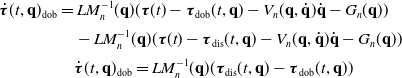 \begin{align} \dot {\boldsymbol {\tau }}(t, \mathbf {q})_{\text {dob}} &= L{M}_n^{-1}(\mathbf {q})(\boldsymbol {\tau }(t) - \boldsymbol {\tau }_{\text {dob}}(t, \mathbf {q}) - V_n(\mathbf {q}, \dot {\mathbf {q}})\dot {\mathbf {q}} - G_n(\mathbf {q})) \nonumber \\[3pt] &\quad - L{M}_n^{-1}(\mathbf {q})(\boldsymbol {\tau }(t) - \boldsymbol {\tau }_{\text {dis}}(t, \mathbf {q}) - V_n(\mathbf {q}, \dot {\mathbf {q}})\dot {\mathbf {q}} - G_n(\mathbf {q})) \nonumber \\[3pt] &\quad \dot {\boldsymbol {\tau }}(t, \mathbf {q})_{\text {dob}} = L{M}_n^{-1}(\mathbf {q})(\boldsymbol {\tau }_{\text {dis}}(t, \mathbf {q})-\boldsymbol {\tau }_{\text {dob}}(t, \mathbf {q})) \end{align}
If $\boldsymbol {{\dot \tau }}_{dob}$
is subtracted from both side, then Eq. (27) can be formed as follows:
$\boldsymbol {{\dot \tau }}_{dob}$
is subtracted from both side, then Eq. (27) can be formed as follows:
 \begin{align} \dot {\mathbf {e}}(t)_{\text {dis}} + L{M}_n^{-1}(\mathbf {q})\mathbf {e}_{\text {dis}} = \boldsymbol {{\dot \tau }}(t, \mathbf {q})_{\text {dis}} \end{align}
where $\mathbf e_{\text {dis}} = \boldsymbol {\tau _{\text {dob}}} (t, \mathbf q) - \boldsymbol {\tau _{\text {dis}}} (t, \mathbf q) \in \mathbb {R}^6$
.
$\mathbf e_{\text {dis}} = \boldsymbol {\tau _{\text {dob}}} (t, \mathbf q) - \boldsymbol {\tau _{\text {dis}}} (t, \mathbf q) \in \mathbb {R}^6$
.
Assumption 1.
The lumped disturbance $ \boldsymbol {\tau _{\text {dis}}} (t, \mathbf q)$
is bounded by
$ \boldsymbol {\tau _{\text {dis}}} (t, \mathbf q)$
is bounded by $\|\tau _{\text {dis}}\|_{t\gt 0} \leq \delta _1$
, where
$\|\tau _{\text {dis}}\|_{t\gt 0} \leq \delta _1$
, where $\delta _1 \in \mathbb {R}^+$
is a constant.
$\delta _1 \in \mathbb {R}^+$
is a constant.
Assumption 2.
The change rate of the lump disturbance $\boldsymbol {{\dot \tau }}_{dis} (t, \mathbf q)$
is bounded by
$\boldsymbol {{\dot \tau }}_{dis} (t, \mathbf q)$
is bounded by $\|\boldsymbol {{\dot \tau }}_{dis} (t, \mathbf q)|_{t\gt 0} \leq \delta _2$
, where
$\|\boldsymbol {{\dot \tau }}_{dis} (t, \mathbf q)|_{t\gt 0} \leq \delta _2$
, where $\delta _2 \in \mathbb {R}^+$
is a constant.
$\delta _2 \in \mathbb {R}^+$
is a constant.
With Assumptions 1–2 and $L$
strictly positive definite, then it can be shown that the error of disturbance estimation is uniformly ultimately bounded, that is,
$L$
strictly positive definite, then it can be shown that the error of disturbance estimation is uniformly ultimately bounded, that is,
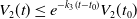
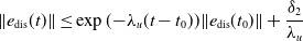 \begin{align} \| e_{\text {dis}}(t) \| \leq \exp ({-}\lambda _u (t - t_0)) \| e_{\text {dis}}(t_0) \| + \frac {\delta _2}{\lambda _u} \end{align}
where $\lambda _u = L M_n^{-1}(q) \gt 0$
.
$\lambda _u = L M_n^{-1}(q) \gt 0$
.
Equation (28) shows that the convergence rate and the accuracy of disturbance estimation are directly adjusted by tuning the nominal inertia matrix and the gain of the DOB.
Replacing the designed DOB $\boldsymbol {\tau _{\text {dob}}} (t, \mathbf q)$
with
$\boldsymbol {\tau _{\text {dob}}} (t, \mathbf q)$
with $\boldsymbol {\tau _{\text {dis}}} (t, \mathbf q)$
in Eq. (23), the control rule becomes as follows:
$\boldsymbol {\tau _{\text {dis}}} (t, \mathbf q)$
in Eq. (23), the control rule becomes as follows:
 \begin{align} \boldsymbol {\tau }(t) = {M}_n(\mathbf {q}) \left (\ddot {\mathbf {q}}_r(t) + k_0 \operatorname {sgn}(\mathbf s(t)) + \eta \mathbf s(t) + \lambda \dot {\mathbf {e}}(t) \right ) +{\boldsymbol {\tau }}_{\text {dob}}(t, \mathbf {q}) + V_n(\mathbf {q}, \dot {\mathbf {q}})\dot {\mathbf {q}} + G_n(\mathbf {q})) \end{align}
where the term $\ddot {\mathbf {q}}_r(t) + \eta \mathbf s(t) + \lambda \dot {\mathbf {e}}(t)$
is called the reference feedforward acceleration, and it can be represented as follows:
$\ddot {\mathbf {q}}_r(t) + \eta \mathbf s(t) + \lambda \dot {\mathbf {e}}(t)$
is called the reference feedforward acceleration, and it can be represented as follows:
 \begin{align} \ddot {\mathbf {q}}_{d}(t) = \ddot {\mathbf {q}}_r(t) (\eta + \lambda ) (\dot {\mathbf {e}}(t) + (\eta \lambda ) \mathbf {e}(t)) = \ddot {\mathbf {q}}_r(t) + k_v \dot {\mathbf {e}}(t) + k_p \mathbf {e}(t) \end{align}
where $k_v$
and
$k_v$
and $k_p$
$k_p$ $\in \mathbb {R}^{6x6}$
are the diagonal velocity and position control gain matrices. Then the controller rule can be obtained as follows:
$\in \mathbb {R}^{6x6}$
are the diagonal velocity and position control gain matrices. Then the controller rule can be obtained as follows:
 \begin{align} \mathbf {u}(t) = {M}_n(\mathbf {q})\left ( \ddot {\mathbf {q}}_d(t) + k_0 \operatorname {sgn}(\mathbf s(t)) \right )+{\boldsymbol {\tau }}_{\text {dob}}(t, \mathbf {q})+V_n(\mathbf {q}, \dot {\mathbf {q}})\dot {\mathbf {q}} + G_n(\mathbf {q})) \end{align}
As can be seen, it is actually a form of acceleration feedforward control with integration of sliding reaching term and DOB. Hence, it represents a hybrid control approach. The controller parameters $k_v$
and
$k_v$
and $k_p$
are tuned by considering the nominal system dynamics only, since the model mismatch and disturbances can be compensated by sliding face and DOB.
$k_p$
are tuned by considering the nominal system dynamics only, since the model mismatch and disturbances can be compensated by sliding face and DOB.
3.1.2. Stability analysis
In order to prove the stability of the proposed controller, let us refer to the following stability theorem:
Stability Theorem: When dealing with a nonlinear uncertain dynamical system as defined by Eq. (15), the application of the robust control law outlined by Eq. (29) ensures asymptotic robust stability of the closed-loop system in the presence of model uncertainties and disturbances.
Proof: Let us consider the following Lyapunov function candidate and its time derivative:
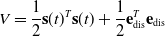 \begin{align} V = \frac {1}{2}\mathbf {s}(t)^T \mathbf {s}(t)+\frac {1}{2}\mathbf {e}_{\text {dis}}^T \mathbf {e}_{\text {dis}} \\[-24pt] \nonumber \end{align}
 \begin{align} \dot {V} = \mathbf {s} \dot {\mathbf {s}} + \mathbf {e}_{\text {dis}} \dot {\mathbf {e}}_{\text {dis}} \end{align}
Inserting control law of Eq. (29) into Eq. (18), one gets sliding face as follows:
 \begin{align} \dot {\mathbf {s}}(t) = -k_0 \operatorname {sgn}\mathbf {s}(t) - \eta \mathbf {s}(t)-M_n^{-1}\mathbf {e}_{\text {dis}} \end{align}
Using Eq. (30) of DOB error dynamic with Assumption2 of the change rate of the lump disturbance $\boldsymbol {{\dot \tau }}_{dis} (t, \mathbf q)$
is bounded by
$\boldsymbol {{\dot \tau }}_{dis} (t, \mathbf q)$
is bounded by $\|\|\boldsymbol {{\dot \tau }}_{dis} (t, \mathbf q)\| \leq \delta _2$
, and taking
$\|\|\boldsymbol {{\dot \tau }}_{dis} (t, \mathbf q)\| \leq \delta _2$
, and taking $\delta _2 = 0$
, and inserting into Eq. (34) into Eq. (33), Eq. (33) yields as follows:
$\delta _2 = 0$
, and inserting into Eq. (34) into Eq. (33), Eq. (33) yields as follows:
 \begin{align} \dot {V} = \mathbf {s}(t) ({-}k_0 \operatorname {sgn}\mathbf {s}(t) - \eta \mathbf {s}(t)-{M}_n^{-1}\mathbf {e}_{\text {dis}})- L{M}_n^{-1} ||\mathbf {e}_{\text {dis}}||^{2} \end{align}
Expending Eq. (35)
 \begin{align} \dot {V} = -k_0 ||\mathbf {s}(t)|| - \eta ||\mathbf {s}(t)||^{2}-{M}_n^{-1}\mathbf {s}(t)\mathbf {e}_{\text {dis}}- L{M}_n^{-1} ||\mathbf {e}_{\text {dis}}||^{2} \end{align}
where $k_0 \geq M_n^{-1} ||\mathbf {e}_{\text {dis}}||_{max}$
.
$k_0 \geq M_n^{-1} ||\mathbf {e}_{\text {dis}}||_{max}$
.
Consider $||\mathbf {e}_{\text {dis}}(0)|| = ||\mathbf {e}_{\text {dis}}||_{max}$
, we have
$||\mathbf {e}_{\text {dis}}(0)|| = ||\mathbf {e}_{\text {dis}}||_{max}$
, we have $k_0 \geq M_n^{-1} ||\mathbf {e}_{\text {dis}}(0)||$
, then
$k_0 \geq M_n^{-1} ||\mathbf {e}_{\text {dis}}(0)||$
, then
 \begin{align} \dot {V} \leq - \eta ||\mathbf {s}(t)||^{2}-L M_n^{-1} ||\mathbf {e}_{\text {dis}}||^{2} \leq -k_1 \left (\frac {1}{2}\mathbf {s}(t)^T \mathbf {s}(t)+\frac {1}{2}\mathbf {e}_{\text {dis}}^T \mathbf {e}_{\text {dis}}\right ) = -k_1 V \end{align}
where $k_1 = 2\min \{ \eta, LM_n^{-1} \}$
.
$k_1 = 2\min \{ \eta, LM_n^{-1} \}$
.
The following lemma can be used to the solution of the inequality of Eq. (37):
Lemma. [Reference Liu36]–[Reference Ioannou and Sun37 ]
Let $f, V: [0, \infty ) \in \mathbb {R}$
, then
$f, V: [0, \infty ) \in \mathbb {R}$
, then $\dot {V} \leq -\alpha V + f$
for
$\dot {V} \leq -\alpha V + f$
for $\forall t \geq t_0 \geq 0$
implies that
$\forall t \geq t_0 \geq 0$
implies that
 \begin{align} V(t) \leq e^{2\alpha (t - t_0)} V(t_0) + \int _{t_0}^{t} e^{2\alpha (t - \tau )} f(\tau ) d\tau \end{align}
for any finite constant $ \alpha$
.
$ \alpha$
.
According to [Reference Atassi and Khalil39], we have the proof as follows:
Let $ \omega (t) \triangleq \dot {V} - \alpha V - f$
, we have
$ \omega (t) \triangleq \dot {V} - \alpha V - f$
, we have $ \omega (t) \leq 0$
, and
$ \omega (t) \leq 0$
, and
 \begin{align} \dot {V} = -\alpha V + f + \omega \end{align}
implies that
 \begin{align} V(t) = e^{-\alpha (t - t_0)} V(t_0) + \int _{t_0}^{t} e^{-\alpha (t - \tau )} f(\tau ) d\tau + \int _{t_0}^{t} e^{-\alpha (t - \tau )} \omega (\tau ) d\tau \end{align}
Since $ \omega (t) \lt 0$
and
$ \omega (t) \lt 0$
and $\forall t \geq t_0 \geq 0$
, one has the following inequality:
$\forall t \geq t_0 \geq 0$
, one has the following inequality:
 \begin{align} V(t) \leq e^{-\alpha (t - t_0)} V(t_0) + \int _{t_0}^{t} e^{-\alpha (t - \tau )} f(\tau ) d\tau . \end{align}
Moreover, setting $ f = 0$
, one has
$ f = 0$
, one has $ \dot {V} \leq -\alpha V$
, implying the following inequality:
$ \dot {V} \leq -\alpha V$
, implying the following inequality:
 \begin{align} V(t) \leq e^{-\alpha (t - t_0)} V(t_0) \end{align}
If $ \alpha$
has a positive constant value, then
$ \alpha$
has a positive constant value, then $ V(t)$
will tend to zero exponentially.
$ V(t)$
will tend to zero exponentially.
Using above the lemma, Eq. (37) can be obtained as follows:
 \begin{align} \dot {V} \leq -k_1 V \\[-24pt] \nonumber \end{align}
 \begin{align} V(t) \leq e^{-k_1(t-t_0)} V(t_0) \end{align}
Notice that the right side of inequality decreases linearly as time $t$
increases, and so the function will converge to zero exponentially, showing the stability of the proposed controller.
$t$
increases, and so the function will converge to zero exponentially, showing the stability of the proposed controller.
It is worth noting that the sliding mode part of the control rule leads to oscillations in the controlled system due to the discontinuous nature of the sign function used in the control law. This oscillatory behavior, known as chattering, is also present in the proposed controller described in Eq. (29). To mitigate chattering, a saturation function can be employed, leading to a modification of the control law as follows:
 \begin{align} \text {sat}(\dot {\mathbf {e}} + \lambda \mathbf {e}, \phi ) = \begin{cases} \text {sign}(\dot {\mathbf {e}} + \lambda \mathbf {e}) & \text {if } |\dot {\mathbf {e}} + \lambda \mathbf {e}| \leq \phi \cr \dfrac {\dot {\mathbf {e}} + \lambda \mathbf {e}}{\phi } & \text {if } |\dot {\mathbf {e}} + \lambda \mathbf {e}| \gt \phi \end{cases} \end{align}
The final tracking error $e$
can be constrained within a specified precision
$e$
can be constrained within a specified precision $\varepsilon$
, known as the boundary layer width as specified in ref. [Reference Slotine and Li20]. The tracking error
$\varepsilon$
, known as the boundary layer width as specified in ref. [Reference Slotine and Li20]. The tracking error $e$
can be calculated as follows:
$e$
can be calculated as follows:
 \begin{align} \varepsilon = \frac {\phi }{\lambda } \end{align}
Equation (46) indicates that the final maximum tracking error can be regulated by appropriately selecting the boundary layer $\phi$
and the slope constant
$\phi$
and the slope constant $\lambda$
. Then, the final form of the hybrid joint-space control rule to be tuned is as follows:
$\lambda$
. Then, the final form of the hybrid joint-space control rule to be tuned is as follows:
 \begin{align} \mathbf {u}(t) = \mathbf {M}_n(\mathbf {q})\left ( \ddot {\mathbf {q}}_d(t) + k_0 \text {sat}(\dot {\mathbf {e}} + \lambda \mathbf {e}, \phi ) \right )+{\boldsymbol {\tau }}_{\text {dob}}(t, \mathbf {q}) \end{align}
3.2. Combined control approach
Joint-space control of parallel robots is often preferred due to its simplicity. However, this method comes with significant drawbacks, as mechanical components like ball screws, spherical and prismatic joints, belt pulleys, and couplings introduce disturbance sources such as backlash and flexibility. These imperfections can lead to significant tracking errors, preventing the robot’s ability to perform precise motion control. In order to address these limitations, a dual approach that combines joint-space control and task-space control is proposed. This dual or combined strategy leverages the strengths of both control spaces: joint-space control manages the movement of individual joints, while task-space control ensures the accurate positioning and orientation of the robot’s end-effector. Integrating these two control mechanisms can significantly enhance the robot’s precision, making it adept for tasks that demand high levels of accuracy and reliability.
Based on the joint-space formulation of the robot dynamics, the equations of motion can be reestablished in task space by using the manipulator’s Jacobian matrix. The Jacobian relates the joint velocities and accelerations to the end-effector velocities and accelerations as follows:
 \begin{align} \begin{aligned} \dot {\mathbf {X}} &= J\dot {\mathbf {q}} \\[3pt] \ddot {\mathbf {X}} &= J\ddot {\mathbf {q}} + \dot J\dot {\mathbf {q}} \\[3pt] \end{aligned} \end{align}
Furthermore, the Jacobian matrix maps the joint forces to the generalized end-effector forces. Pre-multiplying both sides of Eq. (13) by the transpose of the Jacobian matrix ( $J^T$
), the dynamics of the manipulator are expressed in terms of the task-space variables as follows:
$J^T$
), the dynamics of the manipulator are expressed in terms of the task-space variables as follows:
 \begin{align} J^T [M(\mathbf q) \ddot {\mathbf {q}} + V(\mathbf q,\dot {\mathbf {q}}) \dot {\mathbf {q}} + G(\mathbf q) + F(\dot {\mathbf {q}})] = J^T [{\boldsymbol {\tau }}(t) - \mathbf {d}(t)] \\[-24pt] \nonumber \end{align}
 \begin{align} \Lambda (\mathbf {X}) \ddot {\mathbf {X}} + \mu (\mathbf {X},\dot {\mathbf {X}}) + \mathbf {\rho }(\mathbf {X}) = \mathbf {f}(t) - \mathbf {D}(t) \end{align}
where:
 \begin{align*} &\Lambda (\mathbf {X}) = J^{-T} M(\mathbf {q}) J^{-1} \text { is the inertia matrix in task space,} \\[3pt] &\mu (\mathbf {X}, \dot {\mathbf {X}}) = J^{-T}[V(\mathbf {q}, \dot {\mathbf {q}}) - M(\mathbf {q}) \dot {J}] \dot {\mathbf {q}} \text { represents the centripetal-Coriolis terms in task space,} \\[3pt] &\rho (\mathbf {X}) = J^{-T} G(\mathbf {q}) \text { is the gravitational force vector in task space,} \\[3pt] &\mathbf f(t) = J^{-T} {\boldsymbol {\tau }}(t) \text { is the generalized force vector in task space,} \\[3pt] &\mathbf D(t) = J^{-T} \mathbf d(t) \text { represents the external disturbances in task space.} \end{align*}
The end-effector position tracking error is defined as follows:
 \begin{align} \mathbf e_x(t) = \mathbf X_r(t) - \mathbf X(t) \end{align}
where $\mathbf X_r \in \mathbb {R}^6$
is the vector of position reference for the end-effector in task space.
$\mathbf X_r \in \mathbb {R}^6$
is the vector of position reference for the end-effector in task space.
Let us define the PD sliding surface as follows:
 \begin{align} \mathbf {r} (t) = k\dot {\mathbf {e}}_x(t) + c\mathbf {e}_x(t) \end{align}
where $r(t) \in \mathbb {R}^6$
is the sliding surface,
$r(t) \in \mathbb {R}^6$
is the sliding surface, $\dot {\mathbf {X}}_r(t) - \dot {\mathbf {X}}(t) = \dot {\mathbf {e}}_x(t) \in \mathbb {R}^n$
is the end-effector tracking rate error, in which
$\dot {\mathbf {X}}_r(t) - \dot {\mathbf {X}}(t) = \dot {\mathbf {e}}_x(t) \in \mathbb {R}^n$
is the end-effector tracking rate error, in which $\dot {\mathbf {X}}_r(t)\in \mathbb {R}^n$
is the desired velocity trajectory.
$\dot {\mathbf {X}}_r(t)\in \mathbb {R}^n$
is the desired velocity trajectory. $k = \text {diag}(k)$
with
$k = \text {diag}(k)$
with $k \gt 0$
for
$k \gt 0$
for $(i = 1,\ldots, 6)$
is the diagonal positive definite constant matrix and
$(i = 1,\ldots, 6)$
is the diagonal positive definite constant matrix and $c = \text {diag}(c)$
with
$c = \text {diag}(c)$
with $c \gt 0$
for
$c \gt 0$
for $(i = 1,\ldots, 6)$
is the diagonal positive definite constant matrix that determines the slope of the sliding surface.
$(i = 1,\ldots, 6)$
is the diagonal positive definite constant matrix that determines the slope of the sliding surface.
This controller in task space can be converted to joint space by utilizing the Jacobian matrix as follows:
 \begin{align} \mathbf {u}_t = {J}^T \mathbf {r} (t) = {J}^T \left ( k\dot {\mathbf {e}}_x(t) + c \mathbf {e}_x(t) \right ) \end{align}
where $\mathbf {u}_t$
is simple control rule converted from task space to joint space by Jacobian matrix.
$\mathbf {u}_t$
is simple control rule converted from task space to joint space by Jacobian matrix.
Then, combining this task-space control rule with the derived joint-space control rule, the proposed combined control in joint and task space can be obtained as follows:
 \begin{align} \mathbf {u}_c(t) = \mathbf {u}(t) + J^{-T} \mathbf {u}_t(t) = \mathbf {M}_n(\mathbf {q})\left ( \ddot {\mathbf {q}}_d(t) + k_0 \text {sat}(\dot {\mathbf {e}} + \lambda \mathbf {e}, \phi ) \right )+{\boldsymbol {\tau }}_{\text {dob}}(t, \mathbf {q}) +J^{-T} \mathbf {u}_t(t) \end{align}
where $\mathbf {u}_c$
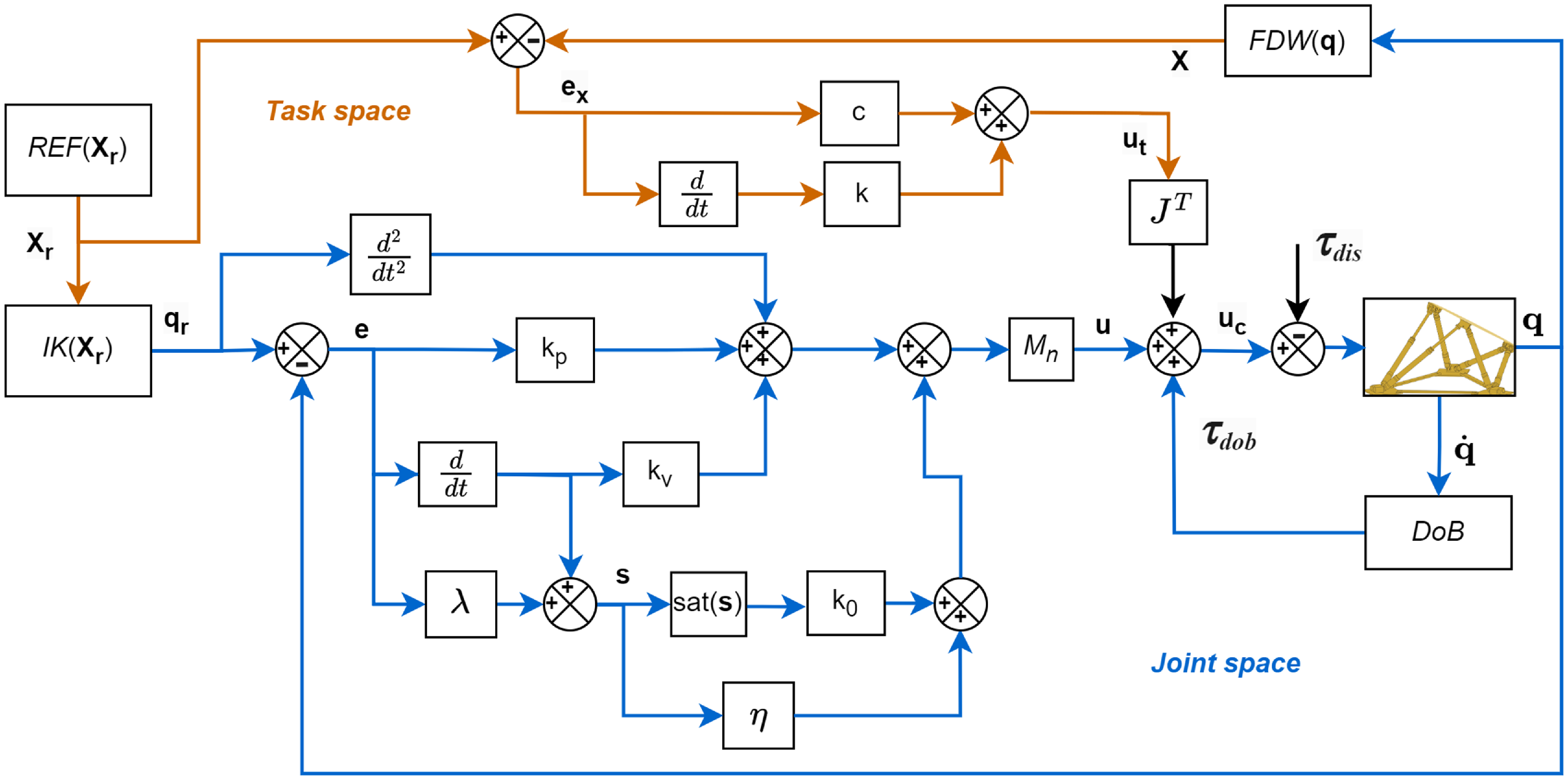
is the combined control rule for both task and joint spaces. The proposed controllers’ block diagram is represented in Figure 2.
$\mathbf {u}_c$
is the combined control rule for both task and joint spaces. The proposed controllers’ block diagram is represented in Figure 2.
Block diagram of the hybrid joint-space control (in blue) and the joint-space/task-space combined control.
One can notice that the combined control law given in Eq. (54) is an extended version of the joint-space hybrid control law proposed in Eq. (31). Parameters such as the nominal dynamic inertia $M_n$
and the observer gain
$M_n$
and the observer gain $L$
(representing the bandwidth of the DOB), as well as the gains for velocity and position errors of the end-effector and joints, should be tuned. This nearly model-free controller is expected to display higher motion control performances than conventional controllers such as the computed torque control methods.
$L$
(representing the bandwidth of the DOB), as well as the gains for velocity and position errors of the end-effector and joints, should be tuned. This nearly model-free controller is expected to display higher motion control performances than conventional controllers such as the computed torque control methods.
The stability and performance analysis of PD control applied to PMs is addressed in ref. [Reference Qu35]. It is important to note that the task-space controller is not implemented as a stand-alone controller in this study. Instead, the task-space controller will be employed as an auxiliary control method to correct the shortcomings of the joint-space controller, thereby ensuring robust performance and stability of the overall system. In the hybrid joint-space control method proposed in Section 3.1, a reaching law and a DOB have been introduced. The combined joint and task-space controller is designed to further enhance controller performance and prevent singularity in PMs. In PMs, the joint-space controller relies upon the leg lengths measured by encoders to determine the end-effector’s position and orientation. However, in certain configurations, the leg lengths may be identical for both positive and negative end-effector positions, leading to ambiguous solutions due to singularities. This presents challenges for the controller in accurately determining joint angles to achieve desired end-effector positions and orientations. The combined controller is based on both joint space and task space, namely, joint and end-effector position. Hence, by integrating both joint and task-space control strategies, the overall system can achieve improved performance and robustness across various operating conditions.
3.2.1. Stability analysis of combined control method
Let us consider the following Lyapunov function candidate $V_2$
and its time derivative:
$V_2$
and its time derivative:
 \begin{align} V_2 = \frac {1}{2}\mathbf {s}(t)^T \mathbf {s}(t)+\frac {1}{2}\mathbf {e}_{\text {dis}}^T \mathbf {e}_{\text {dis}} \end{align}
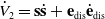 \begin{align} \dot V_2 = \mathbf {s} \dot {\mathbf {s}} + \mathbf {e}_{\text {dis}} \dot {\mathbf {e}}_{\text {dis}} \end{align}
Substituting the combined control law inside the dynamic model in joint space, one gets the following closed-loop acceleration dynamic model:
 \begin{align} \begin{aligned} \ddot {\mathbf {q}}(t) = &\ \ddot {\mathbf {q}}_r(t) + k_0 \operatorname {sgn}(\mathbf {s}(t)) + \eta \mathbf {s}(t) + \lambda \dot {\mathbf {e}}(t) \\[3pt] & + M_n(\mathbf {q})^{-1} \left [\boldsymbol {\tau }_{\text {dob}}(t, \mathbf {q}) - \boldsymbol {\tau }_{\text {dis}}(t, \mathbf {q}) \right ] \\[3pt] & + M_n(\mathbf {q})^{-1} J^T \mathbf {r}(t)) \end{aligned} \end{align}
The time derivative of the sliding surface is given as follows:
 \begin{align} \dot {\mathbf {s}}(t) = \ddot {\mathbf {q}}_r(t) - \ddot {\mathbf {q}}(t) + \lambda (\dot {\mathbf {q}}_r(t) - \dot {\mathbf {q}}(t)) \end{align}
Substituting Eq. (57) into (58) yields as follows:
 \begin{align} \begin{aligned} \dot {\mathbf {s}}(t) = &\ - k_0 \operatorname {sgn}(\mathbf {s}(t)) - \eta \mathbf {s}(t) - M_n(\mathbf {q})^{-1} \mathbf {e}_{\text {dis}}(t) - M_n(\mathbf {q})^{-1} J^T \mathbf {r}(t)) \end{aligned} \end{align}
Now inserting Eq. (59) into Eq. (56) results in the following expression of $\dot V_2$
:
$\dot V_2$
:
 \begin{align} \dot V_2 = \mathbf {s}(t) ({-}k_0 \operatorname {sgn}\mathbf {s}(t) - \eta \mathbf {s}(t)-{M}_n^{-1}\mathbf {e}_{\text {dis}}- M_n(\mathbf {q})^{-1} J^T \mathbf {r}(t)))- L{M}_n^{-1} ||\mathbf {e}_{\text {dis}}||^{2} \end{align}
Considering $||\mathbf {e}_{\text {dis}}(0)|| = ||\mathbf {e}_{\text {dis}}||_{max}$
, and
$||\mathbf {e}_{\text {dis}}(0)|| = ||\mathbf {e}_{\text {dis}}||_{max}$
, and $k_0 \geq M_n^{-1} ||\mathbf {e}_{\text {dis}}(0)||$
, then
$k_0 \geq M_n^{-1} ||\mathbf {e}_{\text {dis}}(0)||$
, then
 \begin{align} \dot V_7 \leq - \eta ||\mathbf {s}(t)||^{2}-L M_n^{-1} ||\mathbf {e}_{\text {dis}}||^{2}-\mathbf {s}(t) M_n(\mathbf {q})^{-1} J^T \mathbf {r}(t) \end{align}
With $k =1$
and
$k =1$
and $\lambda = c$
, the sliding mode in joint-space
$\lambda = c$
, the sliding mode in joint-space $\mathbf {s}(t)$
and sliding mode in task-space
$\mathbf {s}(t)$
and sliding mode in task-space $\mathbf {r}(t)$
have the following relationship:
$\mathbf {r}(t)$
have the following relationship:
 \begin{align} \mathbf {s}(t) = J^T \mathbf {r}(t) \end{align}
Hence, the last terms in $\dot V_2$
equation can be written as follows:
$\dot V_2$
equation can be written as follows:
 \begin{align} -\mathbf {s}(t) M_n(\mathbf {q})^{-1} J^T \mathbf {r}(t) = -\mathbf {s}(t) M_n(\mathbf {q})^{-1} \mathbf {s}(t) \end{align}
This expression now represents a quadratic form involving the vector $\mathbf {s}(t)$
and the inverse of the inertia matrix
$\mathbf {s}(t)$
and the inverse of the inertia matrix $M_n(\mathbf {q})^{-1}$
. When the intention is to interpret the result as a weighted norm, we typically write
$M_n(\mathbf {q})^{-1}$
. When the intention is to interpret the result as a weighted norm, we typically write
 \begin{align} -\mathbf {s}(t)^T M_n(\mathbf {q})^{-1} \mathbf {s}(t) = -M_n(\mathbf {q})^{-1} ||\mathbf {s}(t)||^2 \end{align}
Hence, inserting Eq. (64) into Eq. (60) yields the following:
 \begin{align} \dot V_2 \leq - \eta ||\mathbf {s}(t)||^{2}-L M_n^{-1} ||\mathbf {e}_{\text {dis}}||^{2}-M_n(\mathbf {q})^{-1} ||\mathbf {s}(t)||^2 \end{align}
Factoring out for the same terms:
 \begin{align} \dot V_2 \leq - \left (\eta + M_n^{-1}\right ) ||\mathbf {s}(t)||^2 - L M_n^{-1} ||\mathbf {e}_{\text {dis}}||^{2} \end{align}
 \begin{align} \dot V_2 \leq -k_3 \left (\frac {1}{2}\mathbf {s}(t)^T \mathbf {s}(t)+\frac {1}{2}\mathbf {e}_{\text {dis}}^T \mathbf {e}_{\text {dis}} \right ) \end{align}
 \begin{align} \dot V_2 \leq -k_3 V_2 \end{align}
where $k_3 = 2\min \{ (\eta + M_n^{-1}), LM_n^{-1}\}$
.
$k_3 = 2\min \{ (\eta + M_n^{-1}), LM_n^{-1}\}$
.
Based on the same Lemma [Reference Ioannou and Sun37] again, one gets
 \begin{align} V_2(t) \leq e^{-k_3 (t - t_0)} V_2(t_0) \end{align}
If $k_3$
has a positive constant value, then
$k_3$
has a positive constant value, then $ V_2(t)$
will tend to zero exponentially. Specifically, the right side of inequality decreases linearly as time
$ V_2(t)$
will tend to zero exponentially. Specifically, the right side of inequality decreases linearly as time $t$
increases, and so the function will converge to zero exponentially, showing the stability of the proposed controller.
$t$
increases, and so the function will converge to zero exponentially, showing the stability of the proposed controller.
4. Simulations
To validate proposed control techniques both simulations and experimental tests are conducted. A comprehensive dynamic model of the experimental platform is built in MATLAB/Simulink R2023b environment for a numerical evaluation of the performances of the proposed controllers’ techniques. The dynamic model is built in Simscape Simulink environment. Inverse kinematics, forward kinematics, and Jacobian matrix are coded as MATLAB functions. As detailed in the next section, for the experimental validation of the proposed controller, disturbances corresponding to Level-4 and Level-5 sea states are used as reference signals. Similarly, these sea state disturbances are employed as input signals in the simulation model. To ensure fair comparisons between simulations and real-time experiments, fundamental parameters such as sampling frequency, controller gains, and input signals are kept identical.
Figure 3 depicts the position tracking errors of all six axes of the platform simulated under the Level-4 sea state conditions. Table I details the RMS position tracking errors for the 6-DoF of the moving platform, comparing the performances of the considered controllers. Figure 4 depicts the position tracking errors of all six axes of the platform simulated under the Level-5 sea state conditions. Table II details the RMS position tracking errors for the 6-DoF of the moving platform, comparing the performances of the considered controllers. Simulation results show that the hybrid controller nearly halved the positional errors, while the combined controller reduced them to about four times compared to the ACC method. Furthermore, the control efforts or leg forces, represented as currents, are of a similar order of magnitude in amplitude. As a result, position tracking precision is improved without requiring additional servomotor power.
Simulation: RMS tracking errors for Level-4 sea state input signals.
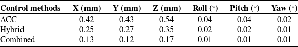
Simulation: RMS tracking errors for Level-5 sea state input signals.
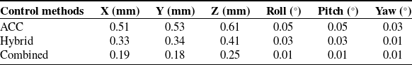
Simulation: end-effector position tracking errors in Level-4 sea state conditions.
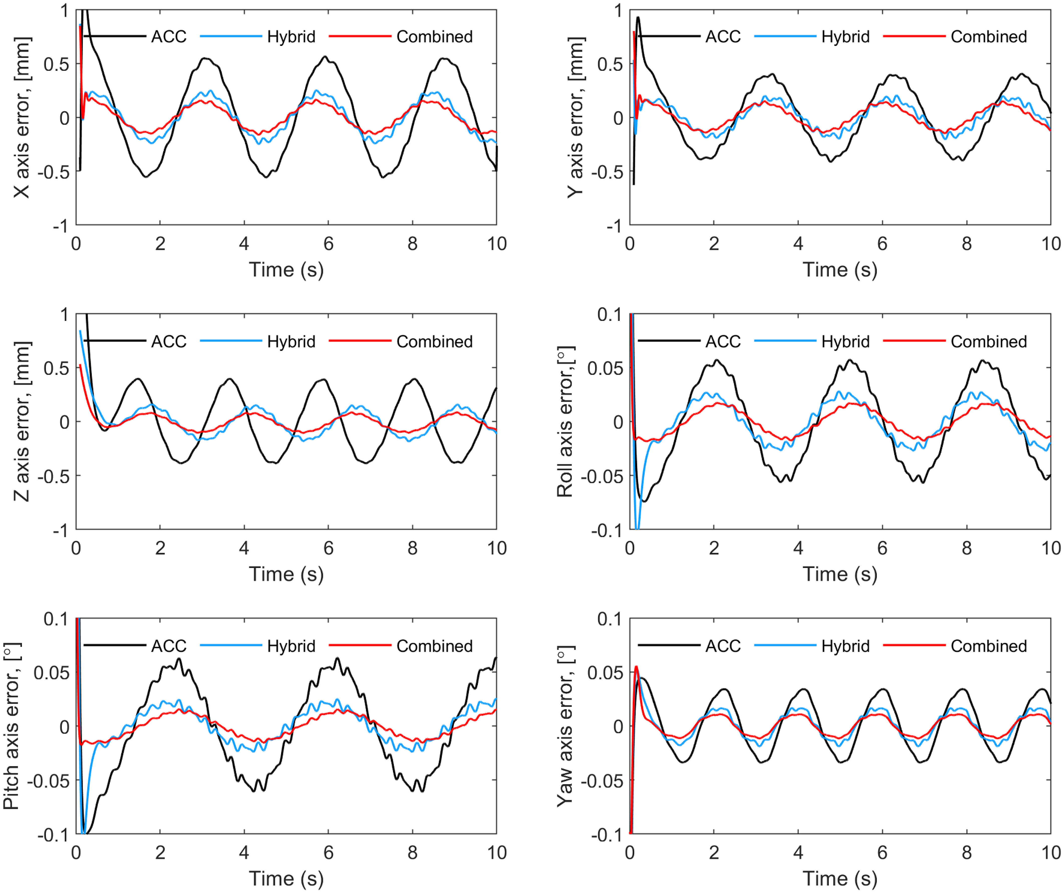
Simulation: end-effector position tracking errors in Level-5 sea state conditions.
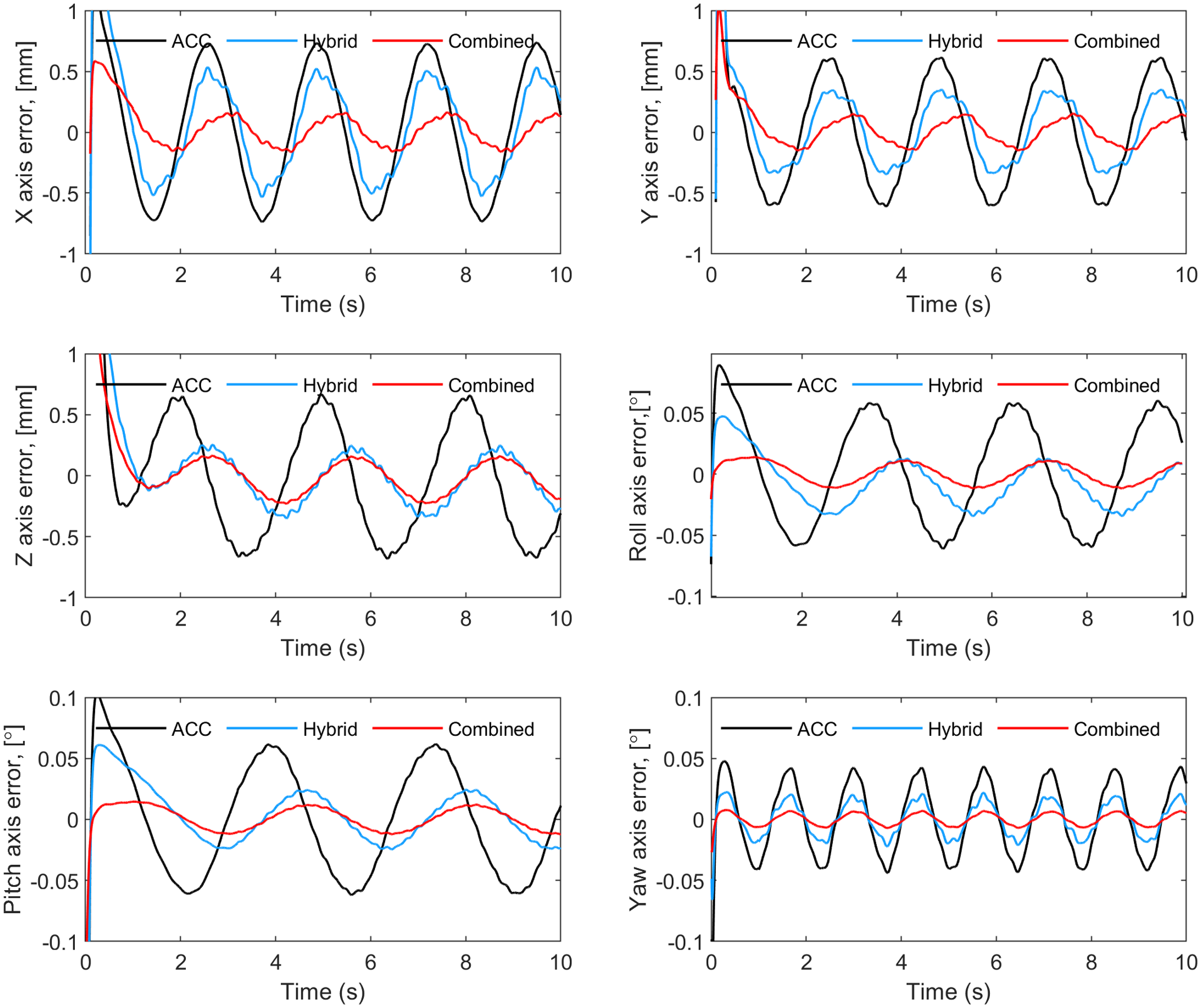
Tables III and IV list the RMS control efforts or control forces in terms of motor currents for x, y, z, roll, pitch, and yaw axes for the Level-4 sea state and Level-5 sea state conditions, respectively. Comparing the simulation results with the experimental results in terms of position tracking errors and control efforts, one can observe a certain consistency between these two analysis approaches. Hence, the performance of the proposed controller methods is verified numerically through detailed modeling and simulations, consistent with real-time experimental results as shown in the next section.
Simulation: RMS currents (in Amp) for Level-4 sea state input signals.
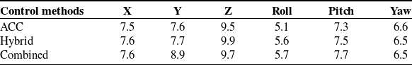
Simulation: RMS currents (in Amp) for Level-5 sea state input signals.
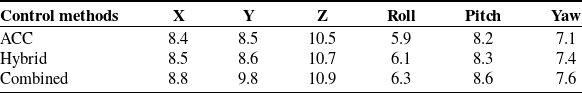
5. Experimentations
The proposed controllers are implemented on a 6-DoF Stewart platform test setup shown in Figure 2. Geometric specification of the test setup is given in Table V. The main components of the platform include universal joints, reducers, servomotors, ball screws, and upper and lower frames. Drivers, power supplies, filters, safety components, and other I/O modules are enclosed in an electrical cabinet. The sensory system consists of inertial measurement units (IMUs), encoders, and limit switches. For joint-space control, the leg lengths are measured by high-resolution encoders integrated into the servomotors. For task-space control, IMUs are located at the center of the upper frame. One IMU is used for control purposes and another for measuring the performance of the proposed controllers. The control algorithm is programmed in C/C++ and implemented on a real-time industrial PC with high sampling frequency. Each of the six legs is controlled separately as a single DoF. The legs are composed of identical servomotors, reducers, joints, bearings, and ball screws. Additionally, the control algorithm and other software are the same for all six legs. So the legs are identical in terms of all hardware and software.
Geometric specification of the test setup.

The payload on the 6-DoF test setup is used on a marine vehicle for stabilization purposes of camera or antenna mostly in the Level-4 and Level-5 sea state conditions. In order to establish a test environment in a laboratory for the payload, the 6-DoF test setup needs to replicate the marine conditions characterized by wave heights and periods. This involves generating time-series data representing the 6-DoF: heave, pitch, roll, surge, sway, and yaw. The generated data should then be scaled appropriately to match Level-4 and Level-5 sea state conditions in workspace limits of the test setup. This setup allows for rigorous testing of the stabilization performance under marine conditions. The aim of the 6-DoF test setup as a controlled system is to track these signals accurately.
In this study, disturbances corresponding to Level-4 and Level-5 sea states are considered as input signals. These inputs represent external disturbances applied to marine vehicles during operations. The Level-4 and Level-5 sea state signals’ amplitudes and frequencies that range from 0.25 Hz to 0.73 Hz and 10 $^{\circ}$
to 15
$^{\circ}$
to 15 $^{\circ}$
are taken from the marine standard document of Interface Standard for Shipboard Systems given in ref. [38]. The payload mass is 50 kg, and the mass moment of inertias are 20, 21, and 18 kg.m
$^{\circ}$
are taken from the marine standard document of Interface Standard for Shipboard Systems given in ref. [38]. The payload mass is 50 kg, and the mass moment of inertias are 20, 21, and 18 kg.m $^2$
around X, Y, and Z axis, respectively. For real-time experiments, the controller parameters are set as
$^2$
around X, Y, and Z axis, respectively. For real-time experiments, the controller parameters are set as $k_p = 80, k_v = 10, k_0 = 20, \lambda = 2, c = 5, k = 2$
. Also, the bandwidth of DOB is
$k_p = 80, k_v = 10, k_0 = 20, \lambda = 2, c = 5, k = 2$
. Also, the bandwidth of DOB is $L = 300$
Hz, and the nominal inertia projected to the motor side is
$L = 300$
Hz, and the nominal inertia projected to the motor side is $M_n = 0.1$
.
$M_n = 0.1$
.
To evaluate the performance of the Stewart platform, it is focused on the position tracking error of the end-effector or moving platform by measuring deviations from the input signals. This involves comparing the actual positions and orientations of the platform with the desired trajectories generated for the 6-DoF: heave, pitch, roll, surge, sway, and yaw. Additionally, control efforts, which include the forces and torques exerted by the actuators, are recorded. These efforts are compared across different control methods to determine which method provides the best performance in terms of minimizing tracking errors and optimizing control efforts. Figure 6 and Figure 7 illustrate the position errors for the x, y, z, roll, pitch, and yaw axes under the Level-4 and Level-5 sea state condition signals, respectively. The performance of acceleration-based (ACC), hybrid joint-space (Hybrid), and combined joint and task-space control (combined) methods are evaluated for all axes. Tables VI and VII present the position tracking error root mean square error for all axes across different control methods. Experimental results indicate that the position errors are reduced by nearly 50% with the proposed hybrid controller compared to the ACC method. Furthermore, when using the proposed combined controller, the position errors are reduced by nearly threefold compared to the ACC method.
6-DoF parallel manipulator for real-time experimental studies.
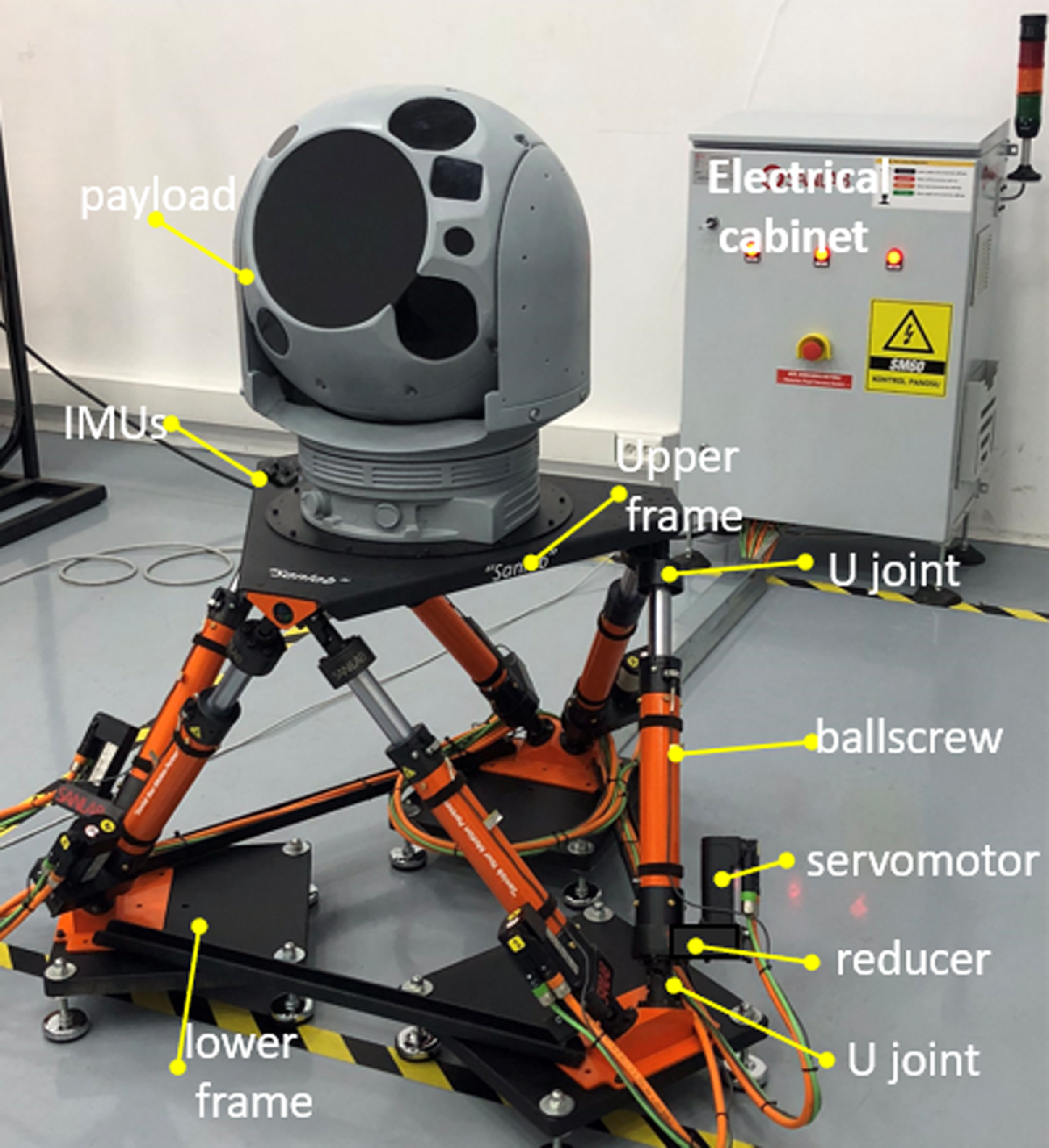
End-effector position errors for X-Y-Z positional and roll-pitch-yaw rotational axes under Level-4 sea state input signals.
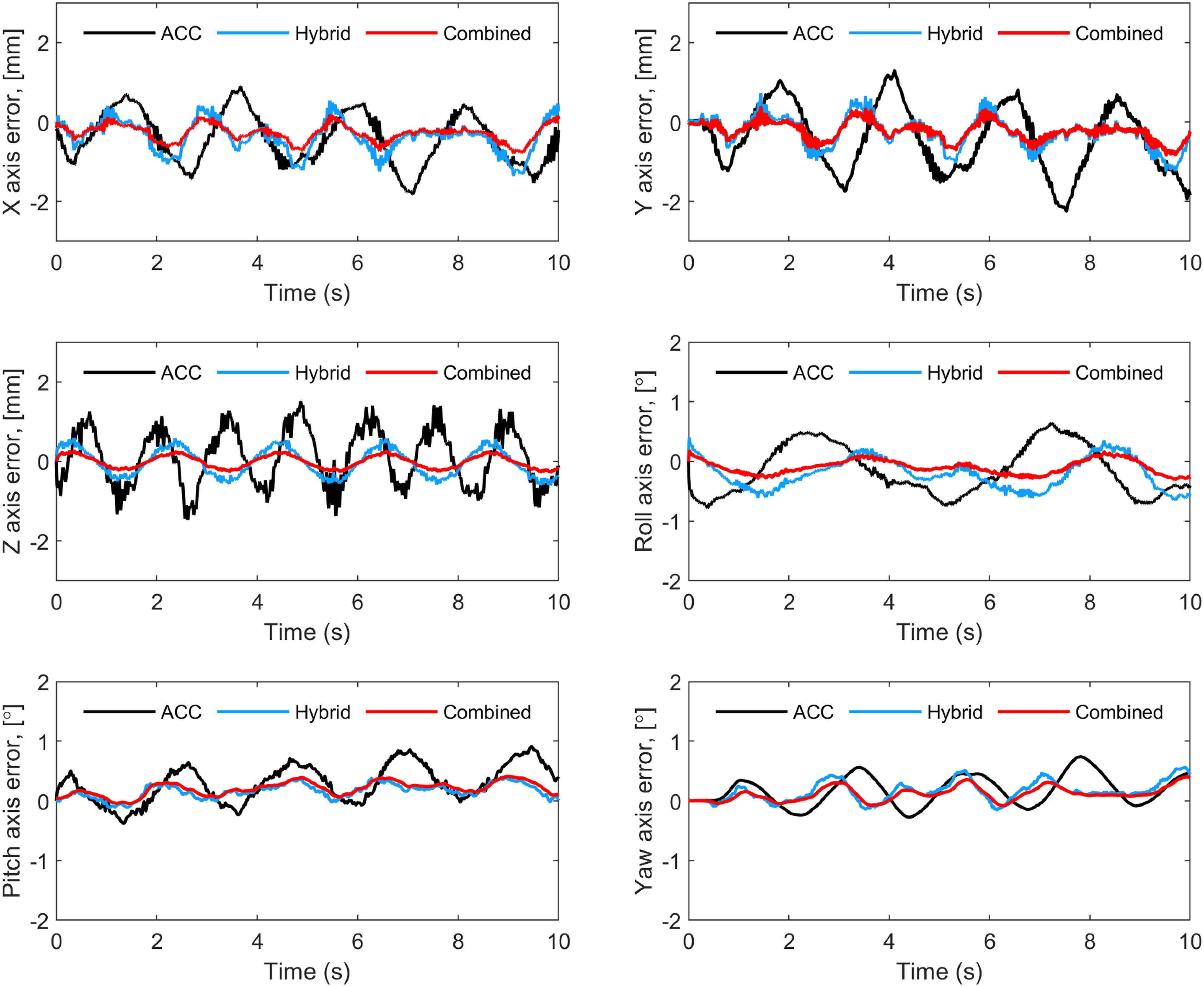
End-effector position errors for X-Y-Z positional and roll-pitch-yaw rotational axes under Level-5 sea state input signals.
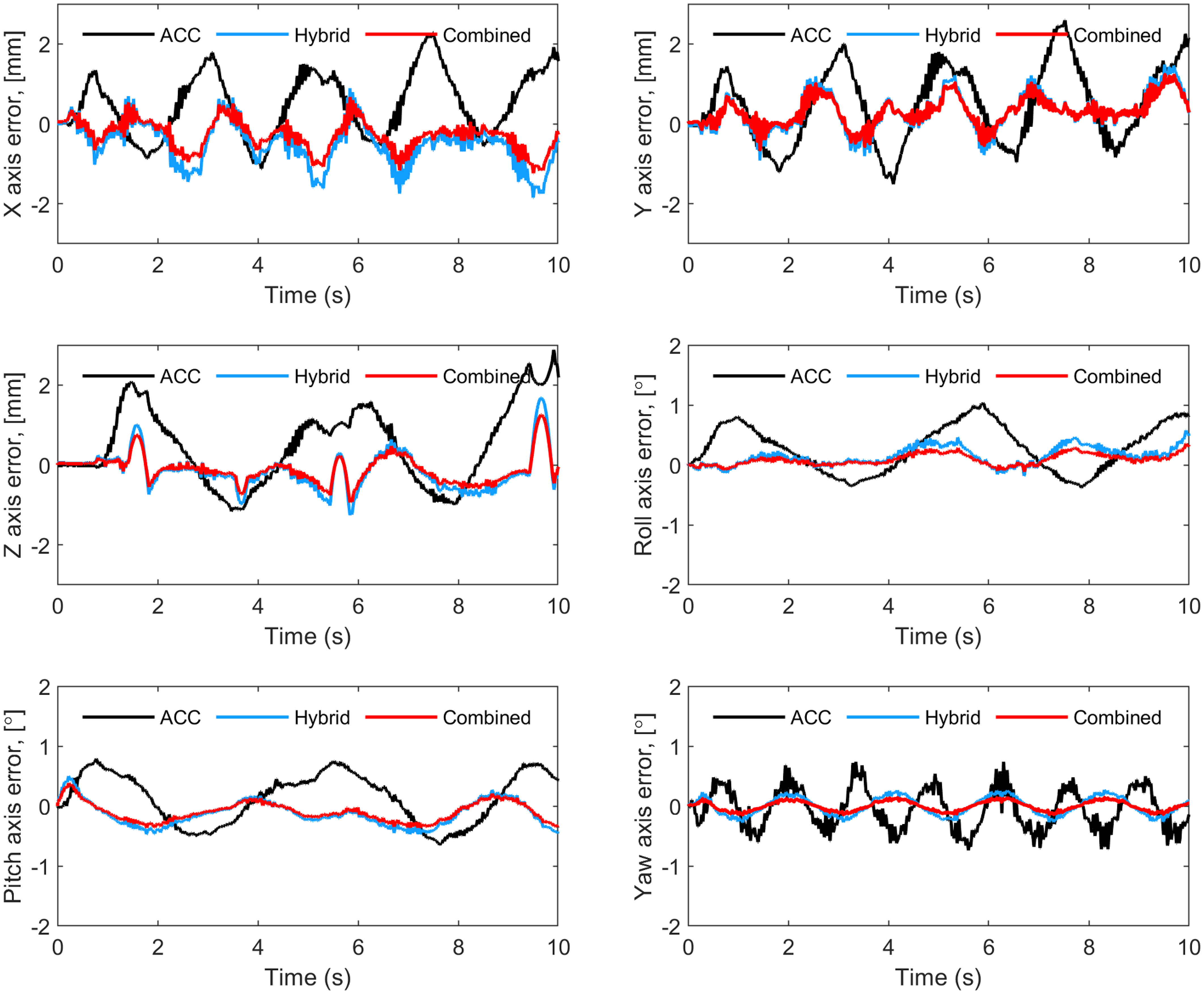
RMS tracking errors for X-Y-Z-roll-pitch-yaw axes under Level-4 sea state input signals.
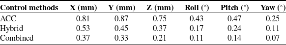
RMS position tracking errors for X-Y-Z-roll-pitch-yaw axes under Level-5 sea state input signals.
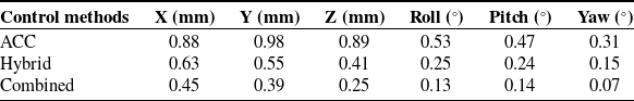
Figures 8 and 9 illustrate the control efforts in terms of currents measured for the first leg of the Stewart platform subjected to Level-4 and Level-5 sea state disturbance signals. Although all six legs are in motion for each axis test, for clarity and brevity, only the current for one motor in the first leg is presented here. However, analogous behavior is observed for the motor currents in the remaining legs. One can observe from Figures 8 and 9 that the ACC controller exhibits noticeable oscillations in control efforts, characterized by significant fluctuations in motor currents. These oscillations indicate instability and can potentially affect the performance of the Stewart platform, as depicted in Figure 6 and Figure 7. However, the proposed hybrid and combined controllers methods effectively mitigate these oscillations and overshoots. Comparative analysis highlights improvements with hybrid and combined controllers compared to the ACC approach, resulting in smoother responses and reduced current oscillations.
Motor currents values of the first leg for X-Y-Z positional and roll-pitch-yaw rotational axes under Level-4 sea state input signals.
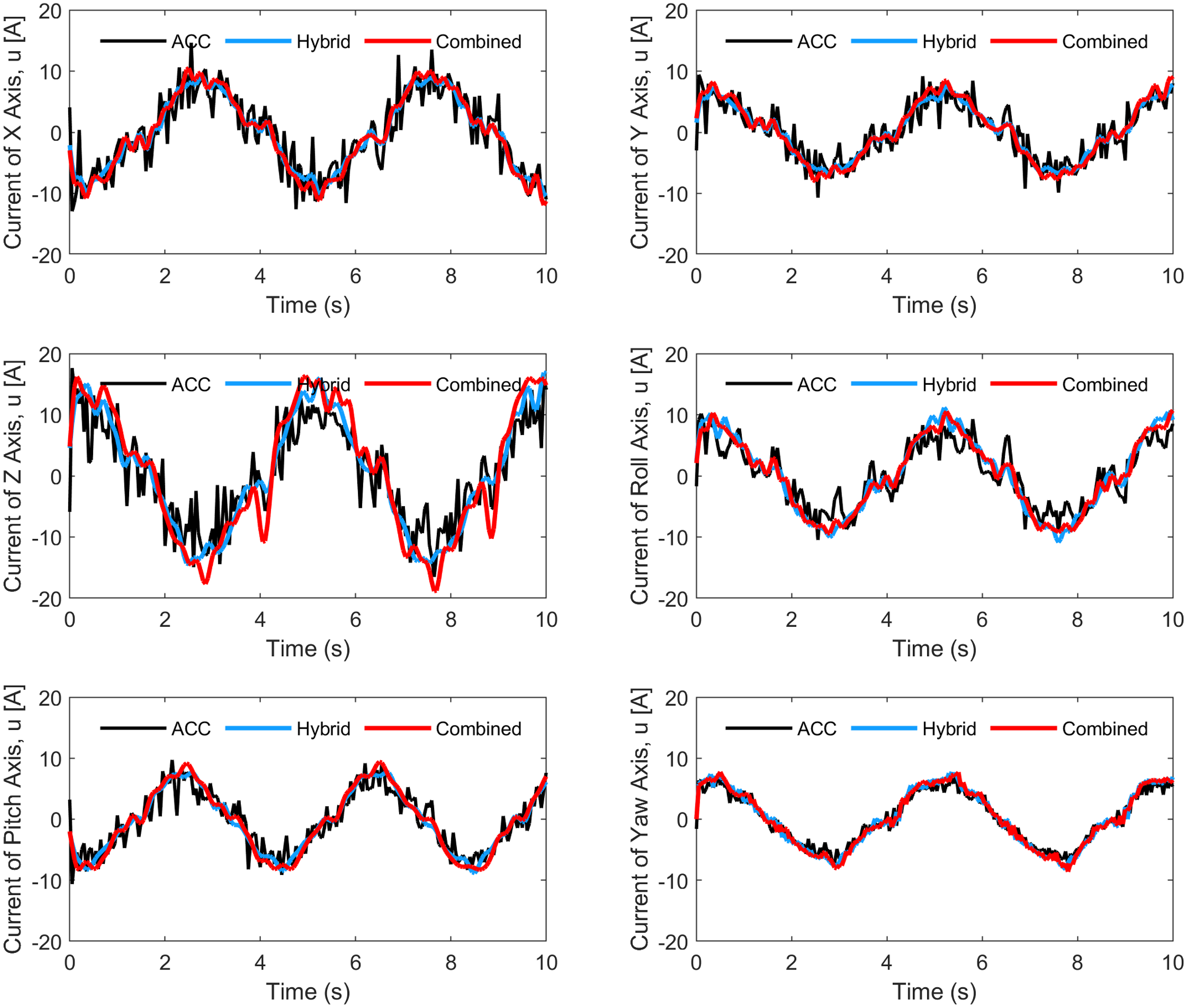
Motor currents values of the first leg for X-Y-Z positional and roll-pitch-yaw rotational axes under Level-5 sea state input signals.
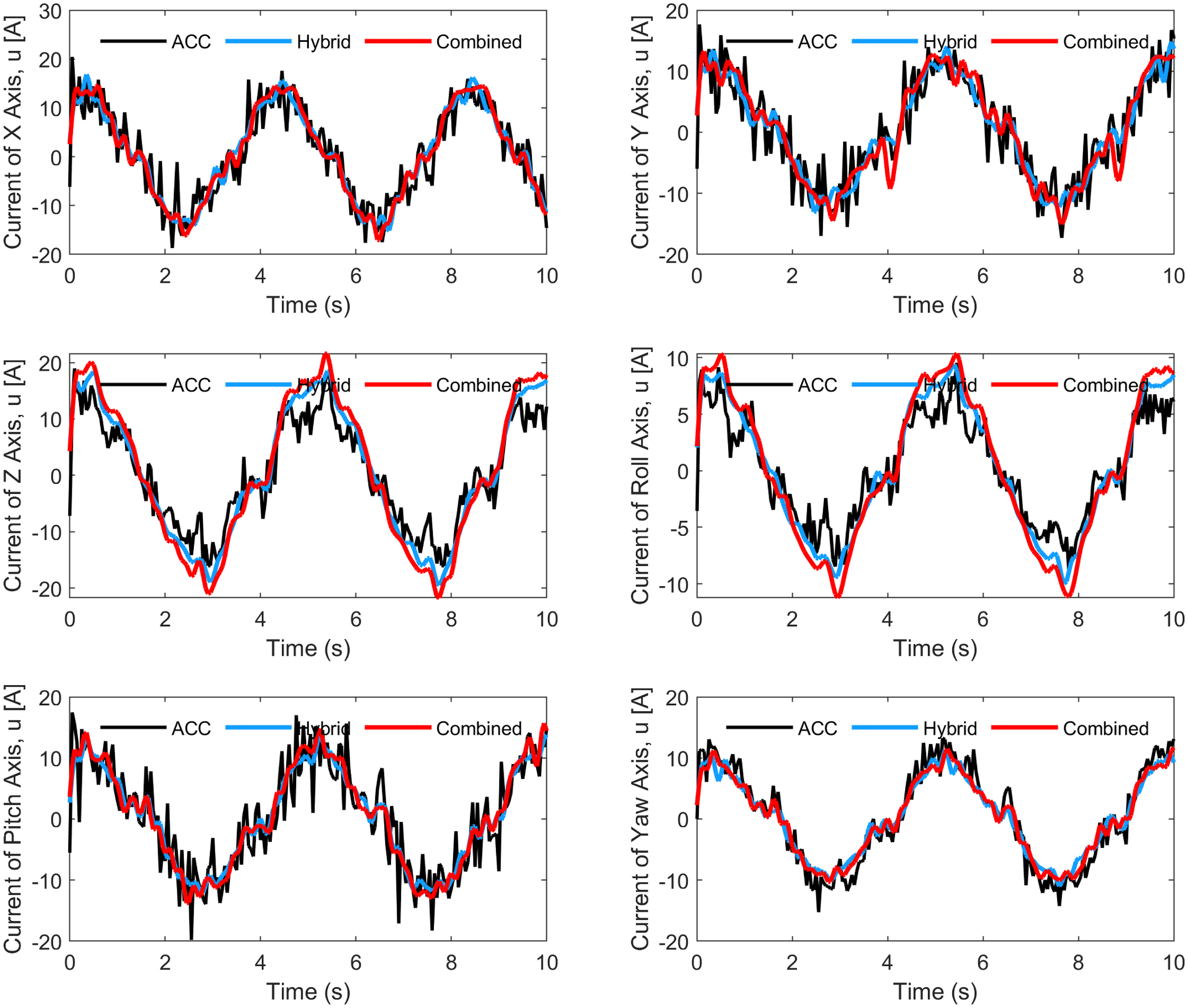
Tables VIII and IX show the root mean square control efforts or leg forces in terms of measured currents of the motor in the first leg under Level-4 and Level-5 sea states, respectively. Although all six legs are in motion for each axis test, for clarity and brevity, only the current for one motor in the first leg is presented here. However, analogous behavior is observed for the motor currents in the remaining legs. This comparison shows that the control efforts are similar order of magnitude in terms of amplitude. Hence, the position tracking precision is enhanced without consuming additional servomotor power.
RMS currents (in Amp) for X-Y-Z-roll-pitch-yaw axes under Level-4 sea state input signals.
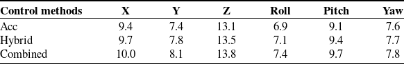
RMS currents (in Amp) for X-Y-Z-roll-pitch-yaw axes under Level-5 sea state input signals.

The results indicate similar performances across both sea states in terms of position tracking errors and control efforts measured in terms of the motor currents drawn. This consistency suggests that the control strategies evaluated are robust across different sea state intensities, demonstrating stable performance in maintaining accurate positioning and effective control of the Stewart platform under varying input signals experimentation.
Figures 10 and 11 further illustrate the frequency spectra of the motor current signals observed in Figure 8 and Figure 9. The introduction of the proposed controllers results in a notable reduction of high-frequency components within the current signals compared to the acceleration-based approach. This enhancement in motor current signal quality plays a critical role in maintaining reliable stabilization of the 6-DoF Stewart platform, thereby improving overall performance and operational effectiveness.
Frequency spectra (through FFT) of the motor currents values of the first leg for X-Y-Z-roll-pitch-yaw axes under Level-4 sea state input signals.
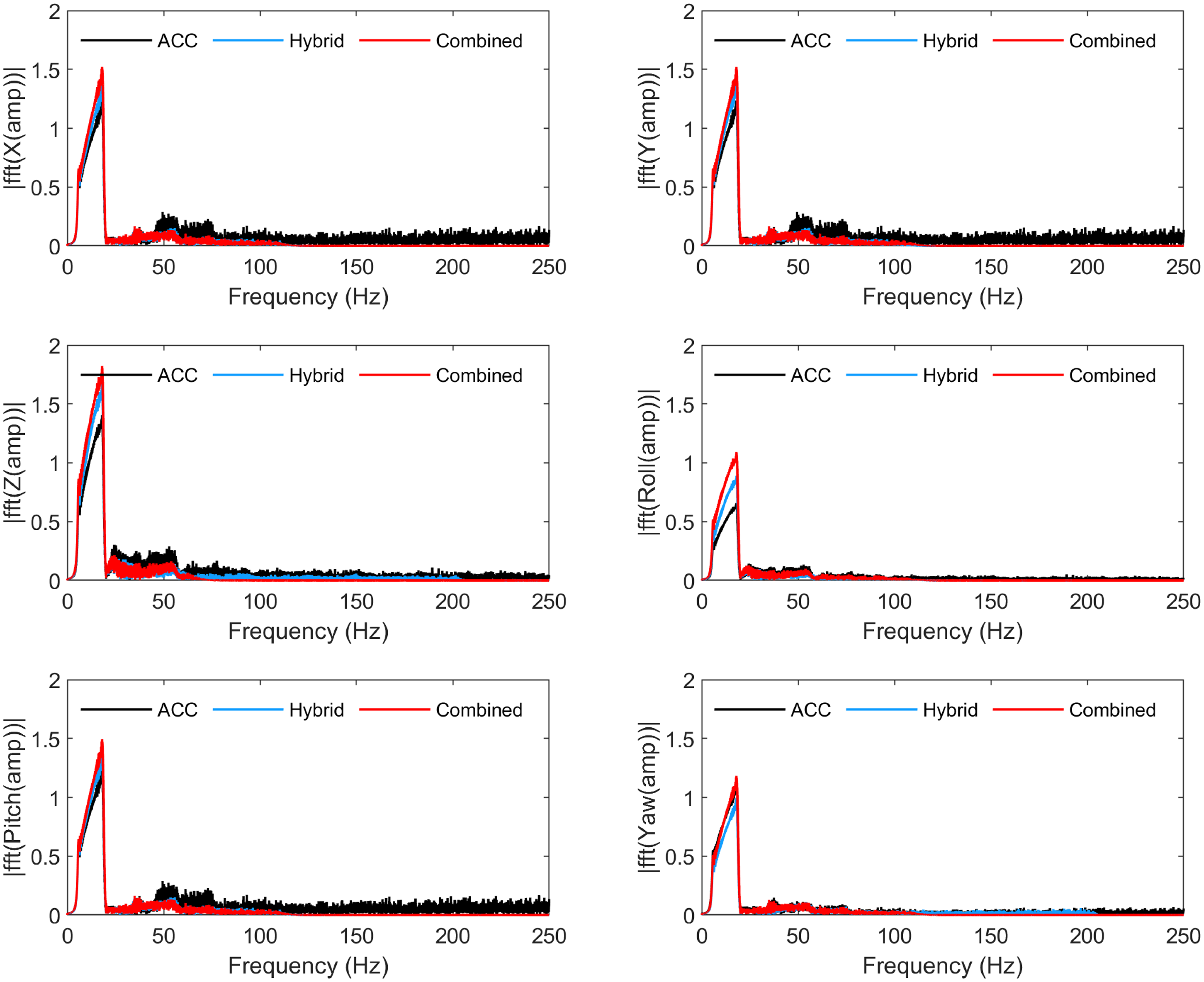
Frequency spectra (through FFT) of the motor currents values of the first leg for X-Y-Z-roll-pitch-yaw axes under Level-5 sea state input signals.
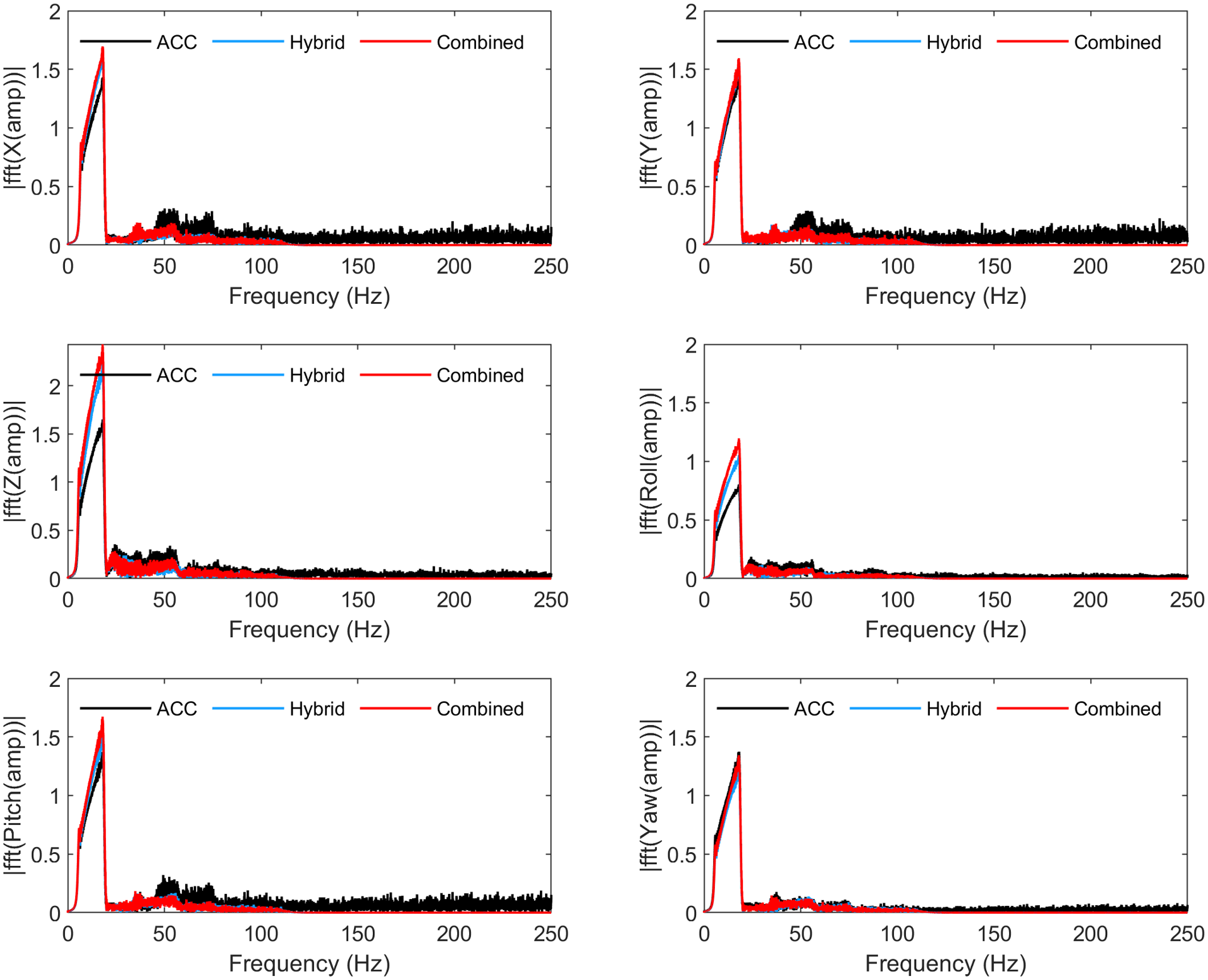
6. Conclusion
This study presents two innovative control strategies that significantly enhance the performance of PMs by addressing their intrinsic nonlinear dynamics and complex structures. The first strategy employs a hybrid control system in joint space, combining AbC, sliding mode, and DOB techniques. This integrated approach effectively corrects errors and compensates for generalized disturbances, leading to improved accuracy in tracking reference positions without the need for an additional sensor. Experimental and simulation results show that this method significantly enhances performance, eliminates current oscillations, and achieves more stable and precise positioning although the control efforts remain comparable in magnitude.
The second strategy integrates the joint-space and task-space controls, using PD-like sliding surface control in task space to precisely manage the end-effector positions while ensuring safe operational configurations. This combined control method produces the best results, achieving high positioning accuracy and increased system stability. Furthermore, the combined joint and task-space controller prevents singularities in PMs. In these manipulators, the joint-space controller uses leg lengths, measured by encoders, to determine the end-effector position and orientation. However, identical leg lengths in certain configurations can cause ambiguity, leading to singularities and making it challenging to accurately determine the joint positions. By integrating the joint-space and task-space control strategies, the combined controller improves overall system performance and robustness.
The efficiency of these proposed control methodologies is validated through the Lyapunov stability analysis, extensive simulations, and real-time experiments. In the experiments, the sea state conditions of Level-4 and Level-5 data (from the Interface Standard for Shipboard Systems) are used to test the performances of the proposed controllers. The results show that both control strategies offer substantial improvements in motion tracking precision and stability of PMs. By enhancing the manipulators’ ability to accurately track the reference trajectories and maintain stability under various operational conditions, these proposed control techniques represent a significant contribution in the field of robotic control systems. Future research may further refine these strategies and explore their applications in more complex and dynamic environments, potentially broadening their scope and impact in industrial and research settings.
Acknowledgements
This study was supported by SANLAB Simulation A.Ş.
Author contributions
The research work of this paper is the result of the joint efforts of the whole team. ES (Eyyup Sincar) conducted the study and wrote the article, while ZYB (Zeki Yagiz Bayraktaroglu) provided comprehensive supervision throughout all stages of the project, including reviewing and editing the article. EAB (Eray A. Baran) made substantial contributions to the concept of design and critical review of the study. EE (Evren Emre) made substantial contributions to the validation of proposed methods including analysis and interpretation of experimental results. All authors contributed to the manuscript preparation and approved the final version.
Financial support
This research received no specific grant from any funding agency, commercial, or not-for-profit sectors.
Competing interests
The authors declare no conflicts of interest exist.
Ethical approval
Not applicable.


 Open access